EP4004340B1 - Schneidvorrichtung - Google Patents
Schneidvorrichtung Download PDFInfo
- Publication number
- EP4004340B1 EP4004340B1 EP19748803.4A EP19748803A EP4004340B1 EP 4004340 B1 EP4004340 B1 EP 4004340B1 EP 19748803 A EP19748803 A EP 19748803A EP 4004340 B1 EP4004340 B1 EP 4004340B1
- Authority
- EP
- European Patent Office
- Prior art keywords
- cutter
- disc
- cutter head
- support
- cutting
- Prior art date
- Legal status (The legal status is an assumption and is not a legal conclusion. Google has not performed a legal analysis and makes no representation as to the accuracy of the status listed.)
- Active
Links
Images


Classifications
-
- E—FIXED CONSTRUCTIONS
- E21—EARTH OR ROCK DRILLING; MINING
- E21C—MINING OR QUARRYING
- E21C27/00—Machines which completely free the mineral from the seam
- E21C27/20—Mineral freed by means not involving slitting
- E21C27/24—Mineral freed by means not involving slitting by milling means acting on the full working face, i.e. the rotary axis of the tool carrier being substantially parallel to the working face
-
- E—FIXED CONSTRUCTIONS
- E21—EARTH OR ROCK DRILLING; MINING
- E21D—SHAFTS; TUNNELS; GALLERIES; LARGE UNDERGROUND CHAMBERS
- E21D9/00—Tunnels or galleries, with or without linings; Methods or apparatus for making thereof; Layout of tunnels or galleries
- E21D9/10—Making by using boring or cutting machines
- E21D9/1006—Making by using boring or cutting machines with rotary cutting tools
- E21D9/1013—Making by using boring or cutting machines with rotary cutting tools on a tool-carrier supported by a movable boom
-
- E—FIXED CONSTRUCTIONS
- E21—EARTH OR ROCK DRILLING; MINING
- E21D—SHAFTS; TUNNELS; GALLERIES; LARGE UNDERGROUND CHAMBERS
- E21D9/00—Tunnels or galleries, with or without linings; Methods or apparatus for making thereof; Layout of tunnels or galleries
- E21D9/10—Making by using boring or cutting machines
- E21D9/1006—Making by using boring or cutting machines with rotary cutting tools
- E21D9/1013—Making by using boring or cutting machines with rotary cutting tools on a tool-carrier supported by a movable boom
- E21D9/102—Making by using boring or cutting machines with rotary cutting tools on a tool-carrier supported by a movable boom by a longitudinally extending boom being pivotable about a vertical and a transverse axis
-
- E—FIXED CONSTRUCTIONS
- E21—EARTH OR ROCK DRILLING; MINING
- E21D—SHAFTS; TUNNELS; GALLERIES; LARGE UNDERGROUND CHAMBERS
- E21D9/00—Tunnels or galleries, with or without linings; Methods or apparatus for making thereof; Layout of tunnels or galleries
- E21D9/10—Making by using boring or cutting machines
- E21D9/1006—Making by using boring or cutting machines with rotary cutting tools
- E21D9/104—Cutting tool fixtures
-
- E—FIXED CONSTRUCTIONS
- E21—EARTH OR ROCK DRILLING; MINING
- E21D—SHAFTS; TUNNELS; GALLERIES; LARGE UNDERGROUND CHAMBERS
- E21D9/00—Tunnels or galleries, with or without linings; Methods or apparatus for making thereof; Layout of tunnels or galleries
- E21D9/10—Making by using boring or cutting machines
- E21D9/1093—Devices for supporting, advancing or orientating the machine or the tool-carrier
Definitions
- the present invention relates to a cutter head and a mining machine suitable for creating tunnels or subterranean roadways and in particular, although not exclusively, to an undercutting apparatus that is capable of cutting hard rock material.
- a variety of different types of excavation machines have been developed for cutting drifts, tunnels, subterranean roadways and the like in which a rotatable head is mounted on an arm so as to create a desired tunnel cross sectional profile.
- a rotatable head is mounted on an arm so as to create a desired tunnel cross sectional profile.
- the creation of the tunnel can be made by horizontal swinging operation of a cutter head, each time only a single layer is cut by pivoting movement of the cutter head in the lateral sideways direction.
- the disc cutters are deposited on the cutter head such that the rotational axes of disc cutters are substantially parallel to the the rotational axes of the cutter head.
- ZA200206394 describes an extraction machine for extracting hard rocks, in which disc or roller tools operating according to the undercut principle are provided with, wherein the disc or roller tools are mounted for rotation on a swivelling jib arm of the machine, with a head carrying the tools, the axis of rotation of which extends essentially in the direction of the jib arm axis, wherein the head carrying the tools on the machine frame is mounted for swivelling around a vertical axis.
- WO0201045 describes a similar mining machine to the above described machine
- WO2014/026761 describes a mobile mining machine 10 which comprises a movable machine base frame 1, a rotatable tool drum 4 and including excavating tools 6.
- Each excavating tool 6 comprises a rotatable tool holder 13 with a support head 14 located outside of the drum housing 7.
- the support head 14 is fitted with a number of tool chisels 15 (see Figures 2 &4).
- US20180363462 describes a milling device 14 comprising a milling drum 15 rotatable about a drum axis 200; a first group of excavating heads 18 and a second group of excavating heads 20 arranged around the periphery of the milling drum 15.
- the first group of excavating heads 18 includes a plurality of first excavating tools 60 configured to perform a first, cutting operation
- the second group of excavating heads 20 includes a plurality of second excavating tools 267 configured to perform a second excavating operation different from the first, cutting operation.
- the group of disc cutters or disc-like roller cutters are arranged on the support portion in a manner that the respective rotational axis of each disc cutter is configured to be substantially transverse to the rotational axis of the cutter head, an individual disc cutter creates a groove or channel into the rock face as the head is driven about its rotational axis.
- the head may then be pivoted laterally so as to overcome the relatively low tensile strength of the overhanging rock to provide breakage via force and energy that is appreciably lower than a more common compressive cutting action provided by cutting picks and the like.
- the individual disc cutter has a characteristically varying cut spacing over a single rotation of the cutter head, and no peak value of reaction force is present at the initial phase of contacting rock and at the end phase of leaving rock.
- each individual disc cutter comprises a single layer of an annular cutting edge - for example a cutting ring, or a single layer of an annular cutting arrangement defined by the outermost cutting tips of a plurality of cutting elements (such as cutting buttons) arranged on the outer periphery of the disc cutter.
- multiple-layer cutting mode multiple layers of rock are sequentially fractured one after another, where each layer is free of confinement at the free face of rock (since a neighbouring layer is already cracked by the previous cutting cycle), individual layers can be broken much easier, thus less energy is consumed, consequently the required overall cutting power decreases.
- multiple-layer cutting mode multiple layers of rock are cracked simultaneously in the same cutting cycle, an inner layer of rock is confined by the outer layer rock and is not easily cracked.
- An example for multiple-layer cutting mode is a conventional milling roller that includes multiple layers of cutting chisels or bit-like tools being arranged spirally over the carrier circumference or being distributed centrically about a rotational axis, for example being placed on a surface of a cylindrical or tapered or conical shaped cutter tool. Such a milling roller is not suitable or not practical for excavating hard rock in undercutting mode.
- a cutter head for excavating hard rock materials in rock face which comprises: a carrier that is attachable to a cutter arm of a cutter apparatus, and a drive shaft rotatably supported by the carrier, the drive shaft being rotatable about a drive axis and comprising at one end a support portion for mounting disc cutters; a plurality of disc cutters mounted on the support portion and configured to perform undercutting against the rock face; wherein each disc cutter is rotatable about a respective support axis, the disc cutters are attached on the support portion substantially in a manner that the support axes of the disc cutters extend to intersect with one another at the drive axis at an intersection point and lie within a common conical surface, wherein the disc cutters are of the same configuration in structure.
- the support axes extend substantially radially with respect to the intersection point, and form a cone-like shape.
- the disc cutters are attached on the support portion in a manner that the support axes of the disc cutters extend to essentially intersect with one another at the drive axis at an intersection point and essentially lie within a common conical surface.
- the disc cutters have annular cutting edges, upon rotation of the cutter head, individual disc cutters may alternatively get contact with the rock face, and after a period of time leave the rock face sequentially, about half of the disc cutters are not in contact with the rock at each time instance.
- the cut has a cut spacing of zero, as the cut continues, the cut spacing gradually increases to a maximum defined by the previous advance distance (sump) of the mining machine. After reaching the maximum the cut spacing decreases to zero until the the tool gets out of contact with the rock.
- the penetration of the disc cutter is however maintained more or less constant at maximal value.
- the main beneficial effects include significantly reduced forces on the disc cutter due to the gradual changing of the cut spacing and and significantly reduced confinement to the disc cutter at the beginning and ending stages of the individual cuts.
- the reduced forces include reduced normal force perpendicular to the advancing direction of the tool and reduced lateral force parallel to the advancing direction of the tool, and advantageously result in less wear and longer tool lifetime, less frequently replacement of disc cutters indicates reduced extra machine down time. Consequently, not only the expense of wear parts is heavily reduced, but also the productivity of the machine is increased.
- Another benefit is the improved rock wall quality due to the gradually increasing cut spacing, especially on the floor, roof and face.
- one support axis may be slightly offset (for example by an offset of ⁇ 15 mm) from a common conical surface defined by the other support axes, and/or do not strictly pass through a common vertex of the other support axes.
- angular deviation it refers to an angle offset in a range between about 0 degree and about ⁇ 20 degrees, preferably in a range between about ⁇ 1 degree and about ⁇ 15 degrees, the support axes of the disc cutters being substantially transverse to the rotational axis of the cutter head, may include (or encompass) a perpendicular alignment.
- the disc cutters represent all cutter tools placed on the cutter head, no other disc cutters placed in other orientation are included.
- the disc cutters are positioned at a same side of the carrier. They may be generally annular or disc shaped roller cutters and comprise a sharp annular cutting edge configured specifically for undercutting hard rock.
- each disc cutter may include a cutter ring or cutter disc in rigid connection to a cutter hub that is rotatably mounted at a disc shaft, each disc shaft is in rigid connection to the support portion (such as a cutter wheel).
- the cutter hub may be fixedly attached to the support portion, and the cutter disc is fixed to the disc shaft rotatable relative to the cutter hub.
- the disc cutters are spaced apart from the intersection point by the same offset.
- the disc cutters are of the same configuration in structure, preferably the disc cutters are uniformly distributed about a circumference in a plane perpendicular to the drive axis. Seen from the intersection point, the disc cutters are uniformly distributed in respective radial direction.
- the cutter head further comprises a flywheel coupled to the drive shaft, for example coupled indirectly via a gear mechanism to the drive shaft, the flywheel is configured for storing rotational energy, and helps to resist rapid changes in rotational speed by their moment of inertia.
- a flywheel coupled to the drive shaft, for example coupled indirectly via a gear mechanism to the drive shaft, the flywheel is configured for storing rotational energy, and helps to resist rapid changes in rotational speed by their moment of inertia.
- each disc cutter comprises a single layer of annular cutting edge, or a single layer of annular cutting arrangement defined by the cutting tips of a plurality of cutting elements arranged on the outer periphery of the disc cutter.
- the cutting elements are in the form of cutting buttons consecutively distributed on the outer periphery of the disc cutter without interruption.
- the support axis of each disc cutter extends inclined relative to the drive axis by a disc inclination angle, preferably the disc inclination angle is in a range between 45 to 89 degrees, more preferably in a range from 60 to 80 degrees.
- the disc inclination angle may be set depending on the diameter of the disc cutters and the separation between an outermost cutting edge of the disc cutter and the drive axis.
- each disc cutter is independently rotatable about the respective support axis via a bearing.
- the cutter head further comprises a motor supported on the carrier, configured to actuate the drive shaft to rotate about the drive axis via a gear mechanism, preferably the gear mechanism comprises a first stage planetary gear coupled in series to a second stage planetary gear.
- the cutter head further comprises a plurality of material cleaning parts deposited between neighbouring disc cutters, and configured to clean material from the rock face.
- the gap between two neighbouring disc cutters is minimised so that the cutter head comprises as many disc cutters as possible, preferably the disc cutters has a diameter of 13 inches.
- a cutter apparatus for creating a tunnel comprising a main frame; a support mounted on the main frame and slidable relative to the main frame in the longitudinal direction of the cutter apparatus; a cutter arm mounted on the support and rotatable about a vertical axis; a cutter head according to any of above described embodiments and mounted at a distal end of the cutter arm.
- the cutter head is coupled to the cutter arm in a way such that a required angular offset of outermost cutting edge is satisfied, the angular offset of outermost cutting edge is defined by two rays starting from a rotation centre at the vertical axis, with one ray towards the outermost cutting edge, and the other ray perpendicular to the drive axis of the cutter head.
- the rotational axis of the cutter head extends substantially transverse to the longitudinal axis of the cutter arm which crosses the vertical axis.
- the cutter head is mounted at a distal end of the cutter arm in a manner that a free-cutting angle is between 30 to 40 degrees, preferably 35 degree. It is observed that the incident angle of a disc cutter has key influence on the cutting efficiency and/or the reacting force on the disc cutter, all disc cutters shall be configured to follow the same effective incident angle.
- the free-cutting angle is defined by the tangent line of the rock face at a contacting point to the rock and a plane defined by the annular cutting edge of the disc cutter, the free-cutting angle is dependent on the disc inclination angle and the angular offset of the outermost cutting edge, and falls within the range of 5 to 40 degrees, preferably, the free-cutting angle is in a range of 20 to 35 degrees.
- the rotation speed of cutter head and the slewing speed of the cutter arm shall be controlled so that a required penetration is met and the machine achieves high productivity.
- the slewing speed of the cutter arm is dependent on the rotation speed of cutter head, the amount of disc cutters, and required penetration.
- the cutter apparatus further comprises a loading means mounted on a lateral side of the cutter head, and configured to collect material that is cut off by the cutter head.
- the cutter apparatus further comprises a slewing gear mechanism or a linear arm actuator to actuate the cutter arm to slew about the vertical axis, and/or a support actuator to actuate the support to slide relative to the main frame.
- the cutter apparatus further comprises a plurality of floor and roof engaging means mounted at the main frame and/or at the support, extendible and retractable to raise and lower the cutter apparatus.
- Figure 1A illustrates a cutter head 100 with the front part in sectional view, the front side of which is indicated by arrow 122
- the cutter head 100 comprises a cylindrical shaped or drum-like body that may be fastened to a suitable holding arm or boom 203
- the body includes a housing or stationary holder 101 which may be tubular form having a chamber as a receptacle for shaft and gear, and a drive shaft 102 that is journaled to the housing 101 freely rotatably by means of bearings 120 such as tapered roller bearings arranged in an O arrangement or X arrangement
- an electronic or hydraulic motor 106 can be mounted on the body for actuating the drive shaft 102 to rotate about a drive axis 103 via a speed reduction mechanism, motor 106 is connected to motor shaft 121 that is supported via bearings 120 on housing 101.
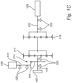
- the speed reduction mechanism includes a bevel gear stage 114 in engagement with a first stage planetary gear 117 which is in series coupled to a second stage planetary gear 118, the carrier of the first stage planetary gear introduces rotation to the sun gear of the second stage planetary gear 118, a bevel gearwheel 116 may be shrink-fit connected to a gear shaft 119, gear shaft 119 is supported via bearings 120 on housing 101, at rear side the gear shaft 119 it is coupled to a flywheel 115, the front side of the gear shaft 119 acts as input to the sun gear of the first stage planetary gear 117.
- the rotation of bevel gear stage 114 is introduced by motor 106 and consequently transferred to shaft 119, finally the carrier of the second stage planetary gear introduces rotation to the drive shaft 102.
- the gear ratio for the bevel gear stage 114, the first stage planetary gear 117 and the second stage planetary gear 118 may be set depending on the properties of motor 106 and a target rotational speed of the cutter head, and may be chosen such that the speed of the drive shaft 102 is in the range of 20-60 rpm.
- the drive shaft 102 projects out of a front end of the housing 101 and includes therein a cutter wheel 109 for mounting a group of disc cutters 104, the cutter wheel 109 and the drive shaft 102 are connected fixedly in terms of rotation to one another or integrally formed in one piece.
- the group of disc cutters 104 are of the same kind of disk roller cutters and have the same design details, i.e. the same in dimension, in structure and in drive mechanism, in other words, they are structurally and functionally identical to each other.
- the arrangement of all disc cutters 104 disclosed herein may have a symmetrical or substantial symmetrical configuration with respect to the drive axis 103.
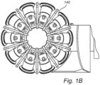
- the disc cutter 104 are mounted in a generally radial direction on the cutter wheel 109 facing outward, uniformly spaced apart from each other on a same outer circumference 140.
- Each disc cutter 104 is freely rotatable about a support axis 105, the support axis 105 may intersect with one another at the drive axis 103 at intersection point 108.
- the support axis 105 of each disc cutter runs inclined relative to the drive axis 103 by a disc inclination angle 107 which shall be substantially the same value for all disc cutters.
- the respective support axes 105 define a conical surface with apex at the intersection point 108.
- the disc inclination angle 107 is dependent on the diameter of the disc cutters and the separation 130 between a centre of cutter ring 112 and the drive axis 103, preferably the disc inclination angle 107 is in a range between 60 to 80 degrees, more preferably the angle 107 is 70 degrees.
- disc cutters 104 are spaced apart from the drum axis 103 by the same offset 130 in radial direction and positioned in the same altitude along the direction of drive axis 103.
- Each disc cutter may include a cutter disc or cutter ring 112 that is rigidly connected on one side to a cutter hub 111 that is in turn rotatably mounted at a disc shaft 124, bearings 125 permit the cutter hub to be freely rotatable around the disc shaft 124, a radially outer portion of each disc 112 by rotation of the disc configured to abrade rock and create a cut groove therein, each disc shaft 124 is of cylindrical shape and in rigid connection to the cutter wheel 109 e.g. via fastening screws.
- annular cutter ring 112 is mounted on the cutter hub 111 via shrink-fit or form-fit or screw bolt connection.
- a plurality of cutter buttons 301 made of diamond or carbide or other hard material are consecutively and uniformly embeded along the outer periphery of the cutter ring, the buttons are oriented to face obliquely outwards with the tips forming a general annular cutter edge.
- a radial outer face with respect to the support axis 105 is indicated by reference symbol 126, the outer face is spaced apart from the intersection point 108 by an offset which is the same value for all disc cutters 104.
- the cutter head 100 further includes a set of shovels 302 mounted fixedly in terms of rotation to the cutter wheel 109, each shovel extends in a respective plane across the drive axis 103, and is positioned between a pair of neighbouring disc cutter 104, by means of the shovel, released material can be loaded into a conveyor (not shown).
- the shovel can be a planar board suitable for scraping off rock deposits left on rock face.
- Figures 1A to 1C are for illustrating purpose, in another embodiment, depending on the amount of disc cutters 104, support axis 105 of a disc cutter and that of an opposite disc cutter may not necessarily be in the same plane.
- FIG 2 illustrates one embodiment of a mining machine 200 for excavating hard rock
- the machine comprises a main frame (chassis) 201 which is coupled to a pair of crawlers (or track wheels), the crawlers are driven via track gear to move the main frame within a tunnel, a support 202 is movably coupled to the main frame 201 and is actuated by linear drive 207 such as a hydraulic actuator to slide on the main frame 201 via a guide (not shown).
- linear drive 207 such as a hydraulic actuator to slide on the main frame 201 via a guide (not shown).
- the support 202 carries a pivoting mechanism 209 that is rotatable about a vertical axis 204, the pivoting mechanism 209 in turn mounts an arm structure 203 which can be cranked or bent, the arm structure 203 at its distal end carries a cutter head 100, optionally via a holder, a pair of actuators 206 such as hydraulic cylinders are coupled to the support 202 to rotate the pivoting mechanism 209 in horizontal plane, such that the cutter head 100 can be slew about an angle in range 0 to 180 degrees from initial position indicated as A (where the drive axis 103 runs substantially parallel to the longitudinal direction of the machine), to a position B.
- a pivoting mechanism 209 that is rotatable about a vertical axis 204, the pivoting mechanism 209 in turn mounts an arm structure 203 which can be cranked or bent, the arm structure 203 at its distal end carries a cutter head 100, optionally via a holder, a pair of actuators 206 such as hydraulic cylinder
- the machine frame can be braced between the tunnel roof and floor by a plurality of jacking legs 208, wherein the jacking legs are arranged on both sides of the longitudinal centre plane of the machine frame.
- the angular offset 210 is defined by two rays starting from a rotation centre at the vertical axis 204, with one ray 212 towards outermost cutting edge, and the other ray 211 perpendicular to the drive axis 103 of the cutter head.
- the angular offset 210 may be set in the range of 0 to 25 degrees.
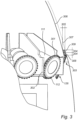
- figure 3 illustrates a cutter head in cutting operation
- the free-cutting angle 303 is defined by the tangent line of the rock face at contacting point to rock and a plane of outer face 126
- the plane of outer face 126 is formed by the annular cutting edge of the disc cutter.
- the free-cutting angle is preferably kept as a small value, it may be set in the range of 5 to 40 degrees, preferably, the free-cutting angle is in the range of 20 to 35 degrees.
- an individual disc cutter 104 is subjected to two rotational movements about two different rotational axes, i.e. in a first rotational movements about the drive axis 103, and in a second rotation about support axis 105.
- the disc cutter 104 is subjected to a pivoting movements about vertical axis 204.
- the disc cutter 104 pierces into mining material, thereby causing cracks in the mining material and eventually creates an undercut or slot.
- a previous cutting path is indicated by reference symbol 306, a succeeding path to be cut is indicated by reference symbol 307, all shown in a horizontal plane.
- a disk cutter first cuts in the base rock along cutting path 307 to remove a free section 308, a succeeding disk roller cutter comes to crush the base rock to remove a free section 309.
- a maximal penetration 304 or undercut depth into the mining material which is in radial direction with respect to the support axis 105, may be set, for example, in a range between about 2 mm and about 20 mm for hard rock mining material.
- a cut spacing 305 which is in radial direction with respect to the drive axis 103, lies in a range of 0 to 150 mm preferably between 5 mm and 70 mm.
- the pivoting speed of the cutter arm is controlled in such a way that, the cutter ring of a succeeding disc cutter 104 comes into contact with the material to be removed at a point which is offset in a common horizontal plane from that of the cutter ring of the preceding disc cutter, wherein the offset corresponds to a required penetration 304.
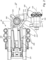
- Figure 4 illustrates another embodiment of a mining machine for excavating hard rock, the machine comprises a main frame 401, a support 402 movably coupled to the main frame 401 via a drawer structure e.g. a rod within a sleeve, and is actuated by an actuator 407 to slide on the main frame 401, a pivoting mechanism 409 carrying a cantilever arm 403 is mounted to the support 402, a cutter head 100 is mounted at the distal end of the cantilever arm.
- the longitudinal axis of cantilever arm 403 is substantially perpendicular to the drive axis of the cutter head.
- the pivoting mechanism 409 includes a rotary drive or slew drive train inside, in order to achieve a specific reduction ratio, the drive train may comprise a first stage planetary drive coupled in series to a second stage planetary drive (not shown).
- a motor 411 is provided as resource to the drive train.
- Jacking legs 408 are connected the main frame. Additional jacking legs 410 may be provided to support the pivoting mechanism 409, optionally the additional jacking legs 410 may have rollers on foot. Other settings of the machine are similar to the machine of figure 2 .
- the machine 200 is set in the required position in the tunnel, depending on needs, operating parameters such as the slewing speed of the cutter arm, rotational speed of the cutter head etc. may be set.
- Jacking legs 208 are actuated to stabilize the machine within the tunnel; then cutter heads 100 is rotated via the motor 106, and cutter arm 203 is actuated to pivot about axis 204 to guide the cutter head to cut from position A to position B, thereafter cutter arm 203 is brought back to position A by pivoting of the arm in reverse direction.
- the support 202 together with the pivoting mechanism 209 is driven to slide forward by a distance corresponding to required sump depth, cutting is repeatedly performed from position A.
- the sliding movement of support 202 and the succeeding cutting can be repeated many times until the maximal forward travel of the support 202 is achieved, then jacking legs 208 are retracted to engage the crawler 406 onto the ground.
- the machine 200 may then be advanced forward via crawler 406. Jacking legs are extended again for repeating the cutting cycle.
- the slewing speed of the cutter arm is set dependent on the rotation speed of cutter head (amounts to 60 rev/min), the amount of disc cutters (8 to 12 pieces), and required penetration (2 to 20 mm).
Landscapes
- Engineering & Computer Science (AREA)
- Mining & Mineral Resources (AREA)
- Life Sciences & Earth Sciences (AREA)
- General Life Sciences & Earth Sciences (AREA)
- Geochemistry & Mineralogy (AREA)
- Geology (AREA)
- Environmental & Geological Engineering (AREA)
- Mechanical Engineering (AREA)
- Earth Drilling (AREA)
- Drilling And Exploitation, And Mining Machines And Methods (AREA)
- Excavating Of Shafts Or Tunnels (AREA)
- Processing Of Stones Or Stones Resemblance Materials (AREA)
Claims (15)
- Schneiderkopf (100) zum Ausheben von Hartgesteinsmaterialien in einer Felswand, umfassendeinen Träger (101), der an einem Schneiderarm (203) einer Schneidereinrichtung (200) befestigbar ist, und eine Antriebswelle (102), die von dem Träger (101) drehbar gestützt wird, wobei die Antriebswelle (102) um eine Antriebsachse (103) herum drehbar ist und einen Stützabschnitt (109) zum Montieren von Scheibenschneidern umfasst;eine Vielzahl von Scheibenschneidern (104), die auf dem Stützabschnitt (109) montiert sind und konfiguriert sind, um Unterschnitte gegen die Felswand durchzuführen;jeder Scheibenschneider (104) um eine jeweilige Stützachse (105) herum drehbar ist, die Scheibenschneider (104) im Wesentlichen auf eine Weise am Stützabschnitt befestigt sind, dass sich die Stützachsen (105) der Scheibenschneider (104) erstrecken, um sich an der Antriebsachse (103) an einem Schnittpunkt (108) zu schneiden und innerhalb einer gemeinsamen konischen Oberfläche zu liegen; dadurch gekennzeichnet, dassdie Antriebswelle (102) an einem Ende den Stützabschnitt (109) zum Montieren von Scheibenschneidern umfasst;wobei die Scheibenschneider (104) strukturell von der gleichen Konfiguration sind.
- Schneiderkopf nach Anspruch 1, wobei die Scheibenschneider (104) vom Schnittpunkt (108) um den gleichen Versatz beabstandet sind.
- Schneiderkopf nach Anspruch 1 oder 2, wobei die Scheibenschneider (104) gleichmäßig um einen Umfang in einer Ebene senkrecht zur Antriebsachse (103) verteilt sind.
- Schneiderkopf nach einem der vorstehenden Ansprüche, der weiter ein Schwungrad (115) umfasst, das mit der Antriebswelle (102) gekoppelt ist.
- Schneiderkopf nach einem der vorstehenden Ansprüche, wobei jeder Scheibenschneider (104) eine einzelne Schicht einer ringförmigen Schneidkante oder eine einzelne Schicht einer ringförmigen Schneidanordnung umfasst, die durch die Schneidspitzen einer Vielzahl von Schneidelementen (301) definiert ist, die am Außenumfang des Scheibenschneiders (104) angeordnet sind.
- Schneiderkopf nach einem der vorstehenden Ansprüche, wobei sich die Stützachse (105) jedes Scheibenschneiders in Bezug zur Antriebsachse (103) um einen Scheibenneigungswinkel (107) geneigt erstreckt, wobei der Scheibenneigungswinkel (107) vorzugsweise in einem Bereich zwischen 60 und 80 Grad liegt.
- Schneiderkopf nach einem der vorstehenden Ansprüche, wobei jeder Scheibenschneider (104) über eine Bohrung unabhängig um die jeweilige Stützachse (105) herum drehbar ist.
- Schneiderkopf nach einem der vorstehenden Ansprüche, der weiter einen Motor (106) umfasst, der auf dem Träger (101) gestützt wird, und konfiguriert ist, um die Antriebswelle (102) zu betätigen, um sich über einen Getriebemechanismus um die Antriebsachse (103) herum zu drehen, wobei der Getriebemechanismus vorzugsweise ein Planetengetriebe (117) der ersten Stufe umfasst, das in Reihe mit einem Planetengetriebe (118) der zweiten Stufe gekoppelt ist.
- Schneiderkopf nach einem der vorstehenden Ansprüche, der weiter eine Vielzahl von Materialreinigungsteilen (302) umfasst, die zwischen benachbarten Scheibenschneidern abgelegt sind und konfiguriert sind, um Material von der Felswand zu reinigen.
- Schneiderkopf nach einem der vorstehenden Ansprüche, wobei der Spalt zwischen zwei benachbarten Scheibenschneidern minimiert ist, sodass der Schneiderkopf möglichst viele Scheibenschneider (104) umfasst, wobei die Scheibenschneider (104) vorzugsweise einen Durchmesser von 13 Zoll aufweisen.
- Schneidereinrichtung (200) zum Erstellen eines Tunnels, die Folgendes umfassteinen Hauptrahmen (201);einen Träger (202), der auf dem Hauptrahmen montiert ist und in Bezug zum Hauptrahmen in der Längsrichtung der Schneidereinrichtung verschiebbar ist;einen Schneiderarm (203), der an dem Träger (202) montiert ist, und um eine vertikale Achse (204) drehbar ist;einen Schneiderkopf (100) nach einem der Ansprüche 1 bis 10, der an einem distalen Ende des Schneiderarms (203) montiert ist.
- Schneidereinrichtung nach Anspruch 11, wobei der Schneiderkopf an einem distalen Ende des Schneiderarms (203) montiert ist, sodass ein durch die Felswand und eine durch die Schneidkante des Scheibenschneiders beim Schneiden gebildete Ebene definierter Freischneidewinkel (303) in einem Bereich von 5 bis 40 Grad, vorzugsweise in einem Bereich von 20 bis 35 Grad liegt.
- Schneidereinrichtung nach Anspruch 11 oder 12, wobei die Schneidereinrichtung weiter ein Lademittel (205) umfasst, die an einer lateralen Seite des Schneiderkopfes montiert ist und konfiguriert ist, um Material aufzusammeln, das vom Schneiderkopf abgeschnitten wird.
- Schneidereinrichtung nach einem der Ansprüche 11 bis 13, die weiter einen Schwenkantriebsmechanismus oder einen Lineararmstellantrieb (206), um den Schneiderarm (203) zu betätigen, um sich um die vertikale Achse (204) herum zu schwenken, und/oder einen Stützstellantrieb (207), um die Stütze (202) zu betätigen, um in Bezug zum Hauptrahmen zu gleiten, umfasst.
- Schneidereinrichtung nach einem der Ansprüche 11 bis 14, die weiter eine Vielzahl von Boden- und Deckeneingriffsmitteln (208) umfasst, die am Hauptrahmen und/oder an dem Träger (402) ausfahrbar und einziehbar montiert sind, um die Schneidereinrichtung anzuheben oder abzusenken.
Applications Claiming Priority (1)
| Application Number | Priority Date | Filing Date | Title |
|---|---|---|---|
| PCT/EP2019/070578 WO2021018390A1 (en) | 2019-07-31 | 2019-07-31 | Cutting apparatus |
Publications (2)
| Publication Number | Publication Date |
|---|---|
| EP4004340A1 EP4004340A1 (de) | 2022-06-01 |
| EP4004340B1 true EP4004340B1 (de) | 2024-10-23 |
Family
ID=67514637
Family Applications (1)
| Application Number | Title | Priority Date | Filing Date |
|---|---|---|---|
| EP19748803.4A Active EP4004340B1 (de) | 2019-07-31 | 2019-07-31 | Schneidvorrichtung |
Country Status (10)
| Country | Link |
|---|---|
| US (1) | US12460545B2 (de) |
| EP (1) | EP4004340B1 (de) |
| CN (1) | CN114207248A (de) |
| AU (1) | AU2019459223B2 (de) |
| CA (1) | CA3145547A1 (de) |
| ES (1) | ES2991415T3 (de) |
| FI (1) | FI4004340T3 (de) |
| MX (1) | MX2022001314A (de) |
| PT (1) | PT4004340T (de) |
| WO (1) | WO2021018390A1 (de) |
Family Cites Families (21)
| Publication number | Priority date | Publication date | Assignee | Title |
|---|---|---|---|---|
| US14483A (en) * | 1856-03-18 | Machine for tumiteling rocks | ||
| US3041055A (en) * | 1959-07-13 | 1962-06-26 | Goodman Mfg Co | Rotatable cutter head |
| DE1275976B (de) * | 1966-11-18 | 1968-08-29 | Georg Schoenfeld | Streckenvortriebsmaschine fuer Tunnel und Strecken im Bergbau mit Bohrwerkzeugen |
| LU68283A1 (de) * | 1973-08-22 | 1975-05-21 | ||
| AT339235B (de) | 1975-09-02 | 1977-10-10 | Voest Ag | Schrammaschine |
| US4548442A (en) * | 1983-12-06 | 1985-10-22 | The Robbins Company | Mobile mining machine and method |
| JP3489092B2 (ja) * | 1998-08-13 | 2004-01-19 | 大石インターナショナルシスコム株式会社 | 坑道掘進工法及び坑道掘進機 |
| AUPP846599A0 (en) * | 1999-02-04 | 1999-02-25 | Sugden, David Burnet | Cutting device |
| JP2001003688A (ja) * | 1999-06-23 | 2001-01-09 | Mitsui Miike Mach Co Ltd | フライホイ−ル付き掘削装置 |
| WO2002001045A1 (de) * | 2000-06-28 | 2002-01-03 | Voest-Alpine Bergtechnik Gesellschaft M.B.H. | Vortriebs- oder gewinnungsmaschine für den abbau von gestein |
| SE522997C2 (sv) * | 2001-02-23 | 2004-03-23 | Sandvik Ab | Verktygshuvud och verktyg |
| SE519284C2 (sv) | 2001-06-21 | 2003-02-11 | Sandvik Ab | Verktygshuvud och verktyg |
| AT411481B (de) | 2001-09-24 | 2004-01-26 | Voest Alpine Bergtechnik | Vortriebs- oder gewinnungsmaschine für den abbau von gestein |
| DE102006040881A1 (de) * | 2006-08-31 | 2008-03-06 | Ulrich Bechem | Vorrichtung zum Abtragen von Gestein und anderen Materialien |
| SE533284C2 (sv) * | 2008-10-31 | 2010-08-10 | Atlas Copco Rock Drills Ab | Förfarande, roterbart skärhuvud, anordning och rigg för drivning av tunnlar, orter, schakt eller liknande |
| PL406775A1 (pl) * | 2011-05-16 | 2014-07-21 | Caterpillar Global Mining Europe Gmbh | Mobilna maszyna górnicza i sposób drążenia tuneli, korytarzy lub szybów, w szczególności w skale |
| DE102012107485A1 (de) | 2012-08-15 | 2014-02-20 | Caterpillar Global Mining Europe Gmbh | Mobile Bergbaumaschine sowie Verfahren zum Auffahren von Tunneln, Strecken oder Schächten, insbesondere in Hartgestein |
| US9366088B2 (en) * | 2013-03-08 | 2016-06-14 | Us Synthetic Corporation | Cutter assemblies, disc cutters, and related methods of manufacture |
| WO2016055087A1 (en) | 2014-10-06 | 2016-04-14 | Sandvik Intellectual Property Ab | Cutting apparatus |
| DE102015016269A1 (de) * | 2015-12-15 | 2017-06-22 | Caterpillar Global Mining Europe Gmbh | Fräsvorrichtung zum abtragen von abbaumaterialien |
| US10094216B2 (en) * | 2016-07-22 | 2018-10-09 | Caterpillar Global Mining Europe Gmbh | Milling depth compensation system and method |
-
2019
- 2019-07-31 EP EP19748803.4A patent/EP4004340B1/de active Active
- 2019-07-31 ES ES19748803T patent/ES2991415T3/es active Active
- 2019-07-31 WO PCT/EP2019/070578 patent/WO2021018390A1/en not_active Ceased
- 2019-07-31 CN CN201980098768.8A patent/CN114207248A/zh active Pending
- 2019-07-31 FI FIEP19748803.4T patent/FI4004340T3/fi active
- 2019-07-31 MX MX2022001314A patent/MX2022001314A/es unknown
- 2019-07-31 US US17/630,572 patent/US12460545B2/en active Active
- 2019-07-31 AU AU2019459223A patent/AU2019459223B2/en active Active
- 2019-07-31 PT PT197488034T patent/PT4004340T/pt unknown
- 2019-07-31 CA CA3145547A patent/CA3145547A1/en active Pending
Also Published As
| Publication number | Publication date |
|---|---|
| CA3145547A1 (en) | 2021-02-04 |
| EP4004340A1 (de) | 2022-06-01 |
| CN114207248A (zh) | 2022-03-18 |
| AU2019459223B2 (en) | 2026-02-19 |
| AU2019459223A1 (en) | 2022-02-17 |
| PT4004340T (pt) | 2024-11-20 |
| FI4004340T3 (fi) | 2024-11-25 |
| BR112022001630A8 (pt) | 2022-05-03 |
| US20220259973A1 (en) | 2022-08-18 |
| WO2021018390A1 (en) | 2021-02-04 |
| MX2022001314A (es) | 2022-05-10 |
| ES2991415T3 (es) | 2024-12-03 |
| US12460545B2 (en) | 2025-11-04 |
| BR112022001630A2 (pt) | 2022-04-19 |
Similar Documents
| Publication | Publication Date | Title |
|---|---|---|
| CN104583537B (zh) | 移动式采矿 | |
| MX2012008715A (es) | Metodo y dispositivo para trabajar rocas. | |
| AU2011325847A1 (en) | Tunneling machine | |
| JP2014515067A (ja) | 岩石、鉱物または他の物質を粉砕切削する装置 | |
| AU2018254652B2 (en) | Cutting apparatus | |
| EP4004340B1 (de) | Schneidvorrichtung | |
| RU2794114C1 (ru) | Режущая головка для выемки твердых горных пород из плоскости забоя и режущее устройство для создания туннеля | |
| US3288532A (en) | Continuous mining machine and method | |
| AU2018255750B2 (en) | Cutting apparatus | |
| EP3615771B1 (de) | Schneidvorrichtung | |
| WO2022243408A1 (en) | Method of mining a rock formation using a disc cutter and a rock breaker tool | |
| CN114876490A (zh) | 破岩方法、破岩装置及掘进装置 | |
| BR112022001630B1 (pt) | Cabeça de corte para escavação de materiais de rocha dura em face de rocha, e aparelho de corte para criação de um túnel | |
| JP2001323780A (ja) | シールド掘進機の回転掘削盤 | |
| CA3056173C (en) | Cutting apparatus | |
| CN221119969U (zh) | 隧道掘进开槽机 | |
| JPH01315592A (ja) | 自由断面シールド機 | |
| CN117905475A (zh) | 隧道掘进开槽机 |
Legal Events
| Date | Code | Title | Description |
|---|---|---|---|
| STAA | Information on the status of an ep patent application or granted ep patent |
Free format text: STATUS: UNKNOWN |
|
| STAA | Information on the status of an ep patent application or granted ep patent |
Free format text: STATUS: THE INTERNATIONAL PUBLICATION HAS BEEN MADE |
|
| PUAI | Public reference made under article 153(3) epc to a published international application that has entered the european phase |
Free format text: ORIGINAL CODE: 0009012 |
|
| STAA | Information on the status of an ep patent application or granted ep patent |
Free format text: STATUS: REQUEST FOR EXAMINATION WAS MADE |
|
| 17P | Request for examination filed |
Effective date: 20220228 |
|
| AK | Designated contracting states |
Kind code of ref document: A1 Designated state(s): AL AT BE BG CH CY CZ DE DK EE ES FI FR GB GR HR HU IE IS IT LI LT LU LV MC MK MT NL NO PL PT RO RS SE SI SK SM TR |
|
| DAV | Request for validation of the european patent (deleted) | ||
| DAX | Request for extension of the european patent (deleted) | ||
| P01 | Opt-out of the competence of the unified patent court (upc) registered |
Effective date: 20230603 |
|
| GRAP | Despatch of communication of intention to grant a patent |
Free format text: ORIGINAL CODE: EPIDOSNIGR1 |
|
| STAA | Information on the status of an ep patent application or granted ep patent |
Free format text: STATUS: GRANT OF PATENT IS INTENDED |
|
| INTG | Intention to grant announced |
Effective date: 20240606 |
|
| GRAS | Grant fee paid |
Free format text: ORIGINAL CODE: EPIDOSNIGR3 |
|
| GRAA | (expected) grant |
Free format text: ORIGINAL CODE: 0009210 |
|
| STAA | Information on the status of an ep patent application or granted ep patent |
Free format text: STATUS: THE PATENT HAS BEEN GRANTED |
|
| AK | Designated contracting states |
Kind code of ref document: B1 Designated state(s): AL AT BE BG CH CY CZ DE DK EE ES FI FR GB GR HR HU IE IS IT LI LT LU LV MC MK MT NL NO PL PT RO RS SE SI SK SM TR |
|
| REG | Reference to a national code |
Ref country code: GB Ref legal event code: FG4D |
|
| REG | Reference to a national code |
Ref country code: CH Ref legal event code: EP |
|
| REG | Reference to a national code |
Ref country code: DE Ref legal event code: R096 Ref document number: 602019060797 Country of ref document: DE |
|
| REG | Reference to a national code |
Ref country code: SE Ref legal event code: TRGR |
|
| REG | Reference to a national code |
Ref country code: PT Ref legal event code: SC4A Ref document number: 4004340 Country of ref document: PT Date of ref document: 20241120 Kind code of ref document: T Free format text: AVAILABILITY OF NATIONAL TRANSLATION Effective date: 20241113 Ref country code: IE Ref legal event code: FG4D |
|
| REG | Reference to a national code |
Ref country code: FI Ref legal event code: FGE |
|
| REG | Reference to a national code |
Ref country code: ES Ref legal event code: FG2A Ref document number: 2991415 Country of ref document: ES Kind code of ref document: T3 Effective date: 20241203 |
|
| REG | Reference to a national code |
Ref country code: LT Ref legal event code: MG9D |
|
| REG | Reference to a national code |
Ref country code: NL Ref legal event code: MP Effective date: 20241023 |
|
| REG | Reference to a national code |
Ref country code: AT Ref legal event code: MK05 Ref document number: 1734982 Country of ref document: AT Kind code of ref document: T Effective date: 20241023 |
|
| PG25 | Lapsed in a contracting state [announced via postgrant information from national office to epo] |
Ref country code: NL Free format text: LAPSE BECAUSE OF FAILURE TO SUBMIT A TRANSLATION OF THE DESCRIPTION OR TO PAY THE FEE WITHIN THE PRESCRIBED TIME-LIMIT Effective date: 20241023 |
|
| PG25 | Lapsed in a contracting state [announced via postgrant information from national office to epo] |
Ref country code: NL Free format text: LAPSE BECAUSE OF FAILURE TO SUBMIT A TRANSLATION OF THE DESCRIPTION OR TO PAY THE FEE WITHIN THE PRESCRIBED TIME-LIMIT Effective date: 20241023 |
|
| PG25 | Lapsed in a contracting state [announced via postgrant information from national office to epo] |
Ref country code: IS Free format text: LAPSE BECAUSE OF FAILURE TO SUBMIT A TRANSLATION OF THE DESCRIPTION OR TO PAY THE FEE WITHIN THE PRESCRIBED TIME-LIMIT Effective date: 20250223 Ref country code: HR Free format text: LAPSE BECAUSE OF FAILURE TO SUBMIT A TRANSLATION OF THE DESCRIPTION OR TO PAY THE FEE WITHIN THE PRESCRIBED TIME-LIMIT Effective date: 20241023 |
|
| PG25 | Lapsed in a contracting state [announced via postgrant information from national office to epo] |
Ref country code: BG Free format text: LAPSE BECAUSE OF FAILURE TO SUBMIT A TRANSLATION OF THE DESCRIPTION OR TO PAY THE FEE WITHIN THE PRESCRIBED TIME-LIMIT Effective date: 20241023 |
|
| PG25 | Lapsed in a contracting state [announced via postgrant information from national office to epo] |
Ref country code: NO Free format text: LAPSE BECAUSE OF FAILURE TO SUBMIT A TRANSLATION OF THE DESCRIPTION OR TO PAY THE FEE WITHIN THE PRESCRIBED TIME-LIMIT Effective date: 20250123 |
|
| PG25 | Lapsed in a contracting state [announced via postgrant information from national office to epo] |
Ref country code: AT Free format text: LAPSE BECAUSE OF FAILURE TO SUBMIT A TRANSLATION OF THE DESCRIPTION OR TO PAY THE FEE WITHIN THE PRESCRIBED TIME-LIMIT Effective date: 20241023 Ref country code: GR Free format text: LAPSE BECAUSE OF FAILURE TO SUBMIT A TRANSLATION OF THE DESCRIPTION OR TO PAY THE FEE WITHIN THE PRESCRIBED TIME-LIMIT Effective date: 20250124 Ref country code: LV Free format text: LAPSE BECAUSE OF FAILURE TO SUBMIT A TRANSLATION OF THE DESCRIPTION OR TO PAY THE FEE WITHIN THE PRESCRIBED TIME-LIMIT Effective date: 20241023 |
|
| PG25 | Lapsed in a contracting state [announced via postgrant information from national office to epo] |
Ref country code: RS Free format text: LAPSE BECAUSE OF FAILURE TO SUBMIT A TRANSLATION OF THE DESCRIPTION OR TO PAY THE FEE WITHIN THE PRESCRIBED TIME-LIMIT Effective date: 20250123 |
|
| PG25 | Lapsed in a contracting state [announced via postgrant information from national office to epo] |
Ref country code: SM Free format text: LAPSE BECAUSE OF FAILURE TO SUBMIT A TRANSLATION OF THE DESCRIPTION OR TO PAY THE FEE WITHIN THE PRESCRIBED TIME-LIMIT Effective date: 20241023 |
|
| PGFP | Annual fee paid to national office [announced via postgrant information from national office to epo] |
Ref country code: PL Payment date: 20250612 Year of fee payment: 7 |
|
| PG25 | Lapsed in a contracting state [announced via postgrant information from national office to epo] |
Ref country code: DK Free format text: LAPSE BECAUSE OF FAILURE TO SUBMIT A TRANSLATION OF THE DESCRIPTION OR TO PAY THE FEE WITHIN THE PRESCRIBED TIME-LIMIT Effective date: 20241023 |
|
| PGFP | Annual fee paid to national office [announced via postgrant information from national office to epo] |
Ref country code: PT Payment date: 20250630 Year of fee payment: 7 |
|
| PG25 | Lapsed in a contracting state [announced via postgrant information from national office to epo] |
Ref country code: EE Free format text: LAPSE BECAUSE OF FAILURE TO SUBMIT A TRANSLATION OF THE DESCRIPTION OR TO PAY THE FEE WITHIN THE PRESCRIBED TIME-LIMIT Effective date: 20241023 |
|
| PG25 | Lapsed in a contracting state [announced via postgrant information from national office to epo] |
Ref country code: RO Free format text: LAPSE BECAUSE OF FAILURE TO SUBMIT A TRANSLATION OF THE DESCRIPTION OR TO PAY THE FEE WITHIN THE PRESCRIBED TIME-LIMIT Effective date: 20241023 |
|
| REG | Reference to a national code |
Ref country code: DE Ref legal event code: R097 Ref document number: 602019060797 Country of ref document: DE |
|
| PG25 | Lapsed in a contracting state [announced via postgrant information from national office to epo] |
Ref country code: SK Free format text: LAPSE BECAUSE OF FAILURE TO SUBMIT A TRANSLATION OF THE DESCRIPTION OR TO PAY THE FEE WITHIN THE PRESCRIBED TIME-LIMIT Effective date: 20241023 |
|
| PG25 | Lapsed in a contracting state [announced via postgrant information from national office to epo] |
Ref country code: CZ Free format text: LAPSE BECAUSE OF FAILURE TO SUBMIT A TRANSLATION OF THE DESCRIPTION OR TO PAY THE FEE WITHIN THE PRESCRIBED TIME-LIMIT Effective date: 20241023 |
|
| PG25 | Lapsed in a contracting state [announced via postgrant information from national office to epo] |
Ref country code: IT Free format text: LAPSE BECAUSE OF FAILURE TO SUBMIT A TRANSLATION OF THE DESCRIPTION OR TO PAY THE FEE WITHIN THE PRESCRIBED TIME-LIMIT Effective date: 20241023 |
|
| PGFP | Annual fee paid to national office [announced via postgrant information from national office to epo] |
Ref country code: SE Payment date: 20250610 Year of fee payment: 7 |
|
| PLBE | No opposition filed within time limit |
Free format text: ORIGINAL CODE: 0009261 |
|
| STAA | Information on the status of an ep patent application or granted ep patent |
Free format text: STATUS: NO OPPOSITION FILED WITHIN TIME LIMIT |
|
| 26N | No opposition filed |
Effective date: 20250724 |
|
| PGFP | Annual fee paid to national office [announced via postgrant information from national office to epo] |
Ref country code: FI Payment date: 20250715 Year of fee payment: 7 Ref country code: ES Payment date: 20250804 Year of fee payment: 7 |
|
| PGFP | Annual fee paid to national office [announced via postgrant information from national office to epo] |
Ref country code: DE Payment date: 20250604 Year of fee payment: 7 |
|
| REG | Reference to a national code |
Ref country code: CH Ref legal event code: H13 Free format text: ST27 STATUS EVENT CODE: U-0-0-H10-H13 (AS PROVIDED BY THE NATIONAL OFFICE) Effective date: 20260224 |
|
| PG25 | Lapsed in a contracting state [announced via postgrant information from national office to epo] |
Ref country code: LU Free format text: LAPSE BECAUSE OF NON-PAYMENT OF DUE FEES Effective date: 20250731 |
|
| GBPC | Gb: european patent ceased through non-payment of renewal fee |
Effective date: 20250731 |
|
| REG | Reference to a national code |
Ref country code: BE Ref legal event code: MM Effective date: 20250731 |
|
| PG25 | Lapsed in a contracting state [announced via postgrant information from national office to epo] |
Ref country code: GB Free format text: LAPSE BECAUSE OF NON-PAYMENT OF DUE FEES Effective date: 20250731 |
|
| PG25 | Lapsed in a contracting state [announced via postgrant information from national office to epo] |
Ref country code: BE Free format text: LAPSE BECAUSE OF NON-PAYMENT OF DUE FEES Effective date: 20250731 |
|
| PG25 | Lapsed in a contracting state [announced via postgrant information from national office to epo] |
Ref country code: FR Free format text: LAPSE BECAUSE OF NON-PAYMENT OF DUE FEES Effective date: 20250731 |
|
| PG25 | Lapsed in a contracting state [announced via postgrant information from national office to epo] |
Ref country code: CH Free format text: LAPSE BECAUSE OF NON-PAYMENT OF DUE FEES Effective date: 20250731 |