EP4004354B1 - Automatic detection of a hardware configuration of a piece of equipment located on-board an aircraft - Google Patents
Automatic detection of a hardware configuration of a piece of equipment located on-board an aircraft Download PDFInfo
- Publication number
- EP4004354B1 EP4004354B1 EP20820478.4A EP20820478A EP4004354B1 EP 4004354 B1 EP4004354 B1 EP 4004354B1 EP 20820478 A EP20820478 A EP 20820478A EP 4004354 B1 EP4004354 B1 EP 4004354B1
- Authority
- EP
- European Patent Office
- Prior art keywords
- current
- hardware configuration
- values
- threshold
- equipment
- Prior art date
- Legal status (The legal status is an assumption and is not a legal conclusion. Google has not performed a legal analysis and makes no representation as to the accuracy of the status listed.)
- Active
Links
Images


Classifications
-
- G—PHYSICS
- G01—MEASURING; TESTING
- G01M—TESTING STATIC OR DYNAMIC BALANCE OF MACHINES OR STRUCTURES; TESTING OF STRUCTURES OR APPARATUS, NOT OTHERWISE PROVIDED FOR
- G01M15/00—Testing of engines
- G01M15/14—Testing gas-turbine engines or jet-propulsion engines
-
- G—PHYSICS
- G01—MEASURING; TESTING
- G01R—MEASURING ELECTRIC VARIABLES; MEASURING MAGNETIC VARIABLES
- G01R31/00—Arrangements for testing electric properties; Arrangements for locating electric faults; Arrangements for electrical testing characterised by what is being tested not provided for elsewhere
- G01R31/005—Testing of electric installations on transport means
- G01R31/008—Testing of electric installations on transport means on air- or spacecraft, railway rolling stock or sea-going vessels
-
- F—MECHANICAL ENGINEERING; LIGHTING; HEATING; WEAPONS; BLASTING
- F02—COMBUSTION ENGINES; HOT-GAS OR COMBUSTION-PRODUCT ENGINE PLANTS
- F02C—GAS-TURBINE PLANTS; AIR INTAKES FOR JET-PROPULSION PLANTS; CONTROLLING FUEL SUPPLY IN AIR-BREATHING JET-PROPULSION PLANTS
- F02C7/00—Features, components parts, details or accessories, not provided for in, or of interest apart form groups F02C1/00 - F02C6/00; Air intakes for jet-propulsion plants
- F02C7/22—Fuel supply systems
- F02C7/232—Fuel valves; Draining valves or systems
-
- G—PHYSICS
- G01—MEASURING; TESTING
- G01R—MEASURING ELECTRIC VARIABLES; MEASURING MAGNETIC VARIABLES
- G01R19/00—Arrangements for measuring currents or voltages or for indicating presence or sign thereof
- G01R19/0092—Measuring current only
-
- G—PHYSICS
- G01—MEASURING; TESTING
- G01R—MEASURING ELECTRIC VARIABLES; MEASURING MAGNETIC VARIABLES
- G01R19/00—Arrangements for measuring currents or voltages or for indicating presence or sign thereof
- G01R19/165—Indicating that current or voltage is either above or below a predetermined value or within or outside a predetermined range of values
-
- G—PHYSICS
- G01—MEASURING; TESTING
- G01R—MEASURING ELECTRIC VARIABLES; MEASURING MAGNETIC VARIABLES
- G01R31/00—Arrangements for testing electric properties; Arrangements for locating electric faults; Arrangements for electrical testing characterised by what is being tested not provided for elsewhere
- G01R31/50—Testing of electric apparatus, lines, cables or components for short-circuits, continuity, leakage current or incorrect line connections
- G01R31/72—Testing of electric windings
-
- H—ELECTRICITY
- H01—ELECTRIC ELEMENTS
- H01F—MAGNETS; INDUCTANCES; TRANSFORMERS; SELECTION OF MATERIALS FOR THEIR MAGNETIC PROPERTIES
- H01F7/00—Magnets
- H01F7/06—Electromagnets; Actuators including electromagnets
- H01F7/08—Electromagnets; Actuators including electromagnets with armatures
- H01F7/18—Circuit arrangements for obtaining desired operating characteristics, e.g. for slow operation, for sequential energisation of windings, for high-speed energisation of windings
- H01F7/1844—Monitoring or fail-safe circuits
- H01F2007/1855—Monitoring or fail-safe circuits using a stored table to deduce one variable from another
-
- H—ELECTRICITY
- H01—ELECTRIC ELEMENTS
- H01F—MAGNETS; INDUCTANCES; TRANSFORMERS; SELECTION OF MATERIALS FOR THEIR MAGNETIC PROPERTIES
- H01F7/00—Magnets
- H01F7/06—Electromagnets; Actuators including electromagnets
- H01F7/08—Electromagnets; Actuators including electromagnets with armatures
- H01F7/18—Circuit arrangements for obtaining desired operating characteristics, e.g. for slow operation, for sequential energisation of windings, for high-speed energisation of windings
- H01F7/1844—Monitoring or fail-safe circuits
Definitions
- the present invention relates to on-board equipment of an aircraft, in particular fuel regulation equipment in particular for a turbomachine such as a turbojet or a turboprop.
- the protection calculators may be required to control fuel metering and regulation equipment (FMU for Fuel Metering Unit ) .
- FMU Fuel Metering Unit
- the EPMU sends a command to the FMUs to control and/or reduce the fuel injected.
- the invention aims in particular to provide a simple, effective and economical solution to the drawbacks of the current technique set out above.
- the deduction of the hardware configuration of the equipment can be carried out from said one or more values of the measured current I and the electrical current response characteristics of the equipment.
- an FMU such a method, implemented on a protection calculator, allows, during a power-up phase of the equipment, i.e. when the latter is started, to automatically detect the FMU model connected to the protection calculators, and therefore to adapt the control current to each FMU model.
- the current response to a control current is analyzed so as to automatically deduce, i.e. without human intervention, the hardware configuration of each of the devices.
- analyzed we mean that the value of the output current of the device in response to the control current, as well as the temporal variation of the output current are analyzed.
- the solution ensures the control of equipment with heterogeneous hardware configuration, while guaranteeing the protection function against unexpected malfunctions of the turbomachine (in English Hazardous Engine Effects).
- the invention is applicable to any equipment comprising an electric actuator comprising a winding, and therefore having an inductance.
- the invention is applicable thanks to the presence of an electrohydraulic servovalve (EHSV) allowing the control of the fuel metering valve (FMV).
- EHSV electrohydraulic servovalve
- equipment with an inductance L1 between 50 mH and 150 mH is considered as equipment with low inductance.
- Equipment with an inductance L2 between 0.9 H and 1.5 H is considered as equipment with high inductance.
- the method compares the value of the measured current to the minimum output current value of the first device and to the maximum output current value of the second device, at the same time t, in response to the same control current.
- a third threshold thus makes it possible to further identify a first or second defective piece of equipment.
- the hardware configurations of the first and second devices may have the same resistance value.
- the first inductance L 1 may be of the order of 100 mH and the second inductance L 2 may be of the order of 1 H.
- the response time of the equipment to a control current sent by the calculator allows it to identify, for each equipment, its hardware configuration automatically, when they start up.
- the protection calculator can then adapt the levels of these control currents for each of the equipment according to its hardware configuration, i.e. its model.
- the setpoint current can be sent by an on-board protection computer of the aircraft.
- the setpoint current Ic can be of the order of 400 mA.
- steps a) to c) may be performed when the equipment is powered up.
- the equipment may comprise an actuator of a movable member of a fuel metering device, said actuator comprising at least one fixed electric coil and a movable core.
- the electrohydraulic servovalves EHSV
- FMV fuel metering valve
- This document also relates to a protection calculator comprising a processor coupled to a memory such that the aforementioned program is recorded on the memory. Also, this document relates to a protection calculator comprising a processor coupled to a memory on which are recorded instructions for implementing the method as aforementioned when executed on the computer.
- a fuel metering unit (known by the English acronym FMU for Fuel Metering Unit) does not necessarily imply an identical replacement, so that a fuel metering member with a first hardware configuration can be replaced by a metering member with a second hardware configuration different from the first hardware configuration.
- FMU Fuel Metering Unit
- the first model known as FMU Cutback, has a first inductance L1, of the order of 100 mH. Generally, the first inductance of this first model is between 0 mH and 150 mH.
- the second model known as FMU Baseline, has a second inductance L2, of the order of 1 H.
- L2 the second inductance of this second model is between 0.9 H and 1.5 H.
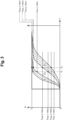
- FIG. 1 illustrates the current response of the first model FMU1 and the second model FMU2 to a setpoint current 2 of the order of 400 mA.
- the current response of the first FMU1 model to this setpoint current is between a maximum output current curve 4 and a minimum output current curve 6. This output current variation depends on the temperature to which the fuel metering device is subjected.
- the current response of the second FMU2 model to this setpoint current is between a maximum output current curve 8 and a minimum output current curve 10.
- zones Z1 and Z2 are delimited, the first zone Z1 representing all the values that can be taken by the output currents of the first FMU1 model and the second zone Z2 representing all the values that can be taken by the output currents of the second FMU2 model. As can be seen in the figure 1 , these zones Z1, Z2 do not overlap.
- the detection method according to the invention relies on this last point to allow automatic detection of the model of fuel metering device used.
- FIG 2 illustrates an embodiment of a method for detecting a hardware configuration of on-board equipment, here a fuel metering device, in an aircraft.
- the two models FMU1 and FMU 2 of fuel metering device are capable of receiving as input a reference current Ic , and, in response to this reference current, of producing as output a current I.
- the dosing device is embedded in an environment, where it is supervised by a two-channel control unit, EPMU, i.e. with two computers for redundancy. protection.
- EPMU i.e. with two computers for redundancy. protection.
- These two calculators for example consisting of two electronic cards in the same housing, are connected to the same FMU, so that in the event of a malfunction of one, the fuel metering device is controlled by the remaining healthy calculator.
- the first step A of the method consists of sending a setpoint current Ic to the equipment input at a given time t 0 .
- the second step B of said method consists of measuring the values of the current I 1 and I 2 at the output of the equipment respectively at times t 1 and t 2 after t 0 .
- this second step for example two measurements of the current response (not shown in the figure 3 ) at the output of the current organ, are carried out at two times t 1 and t 2 after t 0 .
- the instants t 1 and t 2 are chosen for example around 5 ms, so as to define a measurement time interval for example less than 1 ms as illustrated schematically in the figure 1 .
- this comparison allows us to characterize the response time of the fuel metering device and to compare it with the known response time of the first and second models.
- the output currents of the fuel metering device are impacted in response to a control current of the order of 400 mA.
- a third threshold I min 3 it is possible to detect defective equipment.
- An example of an equipment fault is an actuator drift such that its response time goes outside a predefined range when subjected to a current demand.
- Another example of a fault may be a short circuit in a coil of a two-coil actuator.
- the value of 400 mA is reached at 2 ms as can be seen in the Figure 4B .
- the output current value test remains discriminatory.
- the value of 300 mA is reached around 30 ms as can be seen in the Figure 5B .
- the response time is about 15 times higher than the response time of the first configuration, as in the case without short circuit.
- the method is executed by the control unit when the equipment is powered up.
- this method is executed by each of the protection computers of the control unit.
- the protection calculators comprising a processor coupled to a memory, contain in memory a computer program comprising instructions for implementing the method as described above when it is executed on a processor.
Landscapes
- Physics & Mathematics (AREA)
- General Physics & Mathematics (AREA)
- Engineering & Computer Science (AREA)
- Chemical & Material Sciences (AREA)
- Combustion & Propulsion (AREA)
- Mechanical Engineering (AREA)
- General Engineering & Computer Science (AREA)
- Power Engineering (AREA)
- Testing And Monitoring For Control Systems (AREA)
- Testing Of Devices, Machine Parts, Or Other Structures Thereof (AREA)
- Testing Electric Properties And Detecting Electric Faults (AREA)
- Arrangements For Transmission Of Measured Signals (AREA)
Description
La présente invention porte sur les équipements embarqués d'un aéronef, en particulier les équipements de régulation de carburant en particulier pour une turbomachine tel qu'un turboréacteur ou un turbopropulseur.The present invention relates to on-board equipment of an aircraft, in particular fuel regulation equipment in particular for a turbomachine such as a turbojet or a turboprop.
Il existe plusieurs calculateurs embarqués dans les aéronefs visant à la supervision des différents équipements embarqués, afin d'en assurer leur bon fonctionnement. En particulier, les équipements dont le dysfonctionnement est critique nécessitent une supervision par deux calculateurs, l'un des calculateurs étant dédié à la redondance et utilisé en cas de dysfonctionnement de l'autre des calculateurs. Les deux calculateurs forment en général deux voies d'une unité de commande connue sous l'acronyme anglais EPMU pour Electronic and protection monitor unit. There are several computers on board aircraft aimed at supervising the various on-board equipment, in order to ensure their proper functioning. In particular, equipment whose malfunction is critical requires supervision by two computers, one of the computers being dedicated to redundancy and used in the event of a malfunction of the other computer. The two computers generally form two channels of a control unit known by the English acronym EPMU for Electronic and protection monitor unit.
Ces calculateurs sont également appelés calculateurs de protection. Une de leur mission est d'empêcher l'acheminement de carburant vers la turbomachine lorsqu'un dysfonctionnement est identifié pour éviter tout évènement catastrophique.These computers are also called protection computers. One of their missions is to prevent fuel from being delivered to the turbomachine when a malfunction is identified to avoid any catastrophic event.
D'un modèle de turbomachine à l'autre, selon leur architecture, les calculateurs de protection peuvent être amenés à commander des équipements de dosage et régulation de carburant (en anglais FMU pour Fuel Metering Unit). Par exemple, lorsqu'une survitesse de la turbomachine est détectée, l'EPMU envoie une commande aux FMU pour contrôler et/ou réduire le fuel injecté.From one turbomachine model to another, depending on their architecture, the protection calculators may be required to control fuel metering and regulation equipment (FMU for Fuel Metering Unit ) . For example, when an overspeed of the turbomachine is detected, the EPMU sends a command to the FMUs to control and/or reduce the fuel injected.
Il existe différents modèles d'équipements de régulation, présentant des caractéristiques matérielles différentes, et donc en particulier nécessitant des courants de commande d'intensités variables.There are different models of control equipment, with different hardware characteristics, and therefore in particular requiring control currents of varying intensities.
Egalement, il est possible lors des opérations de maintenance de remplacer un premier modèle de FMU par un deuxième modèle de FMU. L'envoi d'un courant de commande d'intensité trop élevé pourrait endommager l'équipement et l'envoi d'un courant de commande trop faible peut impacter la protection de la turbomachine en cas de dysfonctionnement.Also, it is possible during maintenance operations to replace a first FMU model with a second FMU model. Sending a control current of too high intensity could damage the equipment and sending a control current that is too low can impact the protection of the turbomachine in the event of a malfunction.
Aujourd'hui, les informations relatives à l'architecture de la turbomachine, c'est-à-dire le nombre, le positionnement ainsi que le modèle de FMU utilisé est renseigné dans le logiciel applicatif de protection exécuté par les calculateurs de protection.Today, information relating to the architecture of the turbomachine, i.e. the number, positioning and model of FMU used, is entered into the protection application software executed by the protection computers.
Ainsi une modification du modèle de FMU, lors d'une opération de maintenance, nécessite une modification du logiciel applicatif de protection pour éviter tout problème de fonctionnement.Thus, a modification of the FMU model, during a maintenance operation, requires a modification of the protection application software to avoid any operating problems.
L'invention a notamment pour but d'apporter une solution simple, efficace et économique aux inconvénients de la technique actuelle exposée ci-dessus.The invention aims in particular to provide a simple, effective and economical solution to the drawbacks of the current technique set out above.
On connait les documents
A cette fin, il est proposé un procédé de détection d'une configuration matérielle d'un équipement embarqué dans un aéronef tel que défini dans la revendication indépendante 1.For this purpose, a method is proposed for detecting a hardware configuration of equipment on board an aircraft as defined in
La déduction de la configuration matérielle de l'équipement peut être réalisée à partir desdites une ou plusieurs valeurs du courant I mesuré et des caractéristiques électriques de réponse en courant de l'équipement.The deduction of the hardware configuration of the equipment can be carried out from said one or more values of the measured current I and the electrical current response characteristics of the equipment.
Lorsque l'équipement est, par exemple, un FMU, un tel procédé, implémenté sur un calculateur de protection permet, lors d'une phase de mise sous tension des équipements, c'est-à-dire au démarrage de ces derniers, de détecter automatiquement le modèle de FMU relié aux calculateurs de protection, et donc d'adapter le courant de contrôle à chaque modèle de FMU.When the equipment is, for example, an FMU, such a method, implemented on a protection calculator, allows, during a power-up phase of the equipment, i.e. when the latter is started, to automatically detect the FMU model connected to the protection calculators, and therefore to adapt the control current to each FMU model.
Ainsi en s'appuyant sur les caractéristiques électriques des modèles de FMU, il est possible d'en déduire leurs modèles. Pour cela, la réponse en courant à un courant de commande est analysée de sorte à déduire automatiquement, c'est-à-dire sans intervention humaine, la configuration matérielle de chacun des équipements. Par analysé, on entend que la valeur du courant en sortie de l'équipement en réponse au courant de commande, ainsi que la variation temporelle du courant en sortie sont analysées.Thus, by relying on the electrical characteristics of the FMU models, it is possible to deduce their models. To do this, the current response to a control current is analyzed so as to automatically deduce, i.e. without human intervention, the hardware configuration of each of the devices. By analyzed, we mean that the value of the output current of the device in response to the control current, as well as the temporal variation of the output current are analyzed.
Ainsi, en faisant un test discriminant de la configuration, la solution assure le pilotage d'équipement de configuration matérielle hétérogène, tout en garantissant la fonction de protection contre les dysfonctionnements inopinés de la turbomachine (en anglais Hazardous Engine Effects). Thus, by performing a discriminatory test of the configuration, the solution ensures the control of equipment with heterogeneous hardware configuration, while guaranteeing the protection function against unexpected malfunctions of the turbomachine (in English Hazardous Engine Effects).
L'invention est applicable pour tout équipement comprenant un actionneur électrique comportant un bobinage, et donc présentant une inductance. Par exemple, dans le cas d'un FMU, l'invention est applicable grâce à la présence d'une servovalve électrohydraulique (EHSV) permettant la commande de la vanne de dosage de carburant (FMV).The invention is applicable to any equipment comprising an electric actuator comprising a winding, and therefore having an inductance. For example, in the case of an FMU, the invention is applicable thanks to the presence of an electrohydraulic servovalve (EHSV) allowing the control of the fuel metering valve (FMV).
Additionnement, la configuration matérielle d'un équipement peut être au moins l'une des configurations suivantes :
- un premier équipement ayant une première inductance L 1;
- un deuxième équipement ayant une seconde inductance L 2;
- un équipement de configuration matérielle inconnue,

- a first device having a first inductance L 1 ;
- a second device having a second inductance L 2 ;
- equipment with unknown hardware configuration,
Ainsi, l'équipement avec une inductance L1 comprise entre 50 mH et 150mH est considéré comme un équipement avec une faible inductance. L'équipement avec une inductance L2 comprise entre 0,9 H et 1,5 H, est considéré comme un équipement à forte inductance.Thus, equipment with an inductance L1 between 50 mH and 150 mH is considered as equipment with low inductance. Equipment with an inductance L2 between 0.9 H and 1.5 H is considered as equipment with high inductance.
L'étape c) peut consister à comparer les une ou plusieurs valeurs du courant de réponse I mesuré à un premier seuil Imin1,FMU1 et à un second seuil Imax2,FMU2 inférieur au premier seuil, de sorte que :
- un premier équipement est détecté, si les valeurs du courant mesuré I sont supérieures au premier seuil Imin1,FMU1,
- un second équipement est détecté, si les valeurs du courant mesuré I sont inférieures au second seuil, Imax2,FMU2,
- un équipement de configuration matérielle inconnue est détecté si les valeurs du courant mesuré I sont comprises entre le second seuil et le premier seuil.
- a first device is detected, if the values of the measured current I are greater than the first threshold I min1,FMU1 ,
- a second device is detected, if the values of the measured current I are lower than the second threshold, I max2,FMU2 ,
- a device with an unknown hardware configuration is detected if the measured current I values are between the second threshold and the first threshold.
Par conséquent, en faisant une acquisition du courant pendant, le procédé compare la valeur du courant mesuré à la valeur minimale de courant en sortie du premier équipement et à la valeur maximale de courant en sortie du deuxième équipement, au même instant t, en réponse au même courant de commande.Therefore, by acquiring the current during, the method compares the value of the measured current to the minimum output current value of the first device and to the maximum output current value of the second device, at the same time t, in response to the same control current.
De plus, le procédé peut en outre comprendre une étape consistant à :
- mesurer une ou plusieurs valeurs du courant de réponse I à au moins un instant t 3 postérieur à une valeur de borne supérieure t 2 , de l'intervalle de temps de mesure, et
- déduire que la configuration matérielle est celle d'un premier équipement défectueux ou celle d'un second équipement défectueux si les valeurs du courant de réponse mesuré I sont inférieures à un troisième seuil (I min 3 ).
- measuring one or more values of the response current I at at least one time t3 after an upper limit value t2 of the measurement time interval, and
- deduce that the hardware configuration is that of a first faulty equipment or that of a second faulty equipment if the values of the measured response current I are lower than a third threshold (I min 3 ) .
Un troisième seuil permet ainsi de d'identifier en outre un premier ou second équipement défectueux.A third threshold thus makes it possible to further identify a first or second defective piece of equipment.
Les configurations matérielles des premier et second équipements peuvent avoir une même valeur de résistance.The hardware configurations of the first and second devices may have the same resistance value.
De préférence, la première inductance L 1 peut être de l'ordre de 100 mH et la seconde inductance L 2 peut être de l'ordre de 1H. Preferably, the first inductance L 1 may be of the order of 100 mH and the second inductance L 2 may be of the order of 1 H.
En outre, le courant de réponse de l'équipement peut s'exprimer : 
En fonction de la valeur du courant mesuré en sortie de l'équipement, en connaissance de la résistance de cet équipement quelle qu'en soit sa structure, il est possible de déterminer la configuration matérielle de l'équipement, et ceci de manière automatique.Depending on the value of the current measured at the output of the equipment, knowing the resistance of this equipment whatever its structure, it is possible to determine the hardware configuration of the equipment, and this automatically.
En d'autres termes, le temps de réponse de l'équipement à un courant de commande envoyée par le calculateur, permet à celui-ci, d'identifier, pour chacun équipement, sa configuration matérielle de manière automatique, lors de leur démarrage. Ainsi, le calculateur de protection peut ensuite adapter les niveaux de ces courants de commande pour chacun des équipements en fonction de sa configuration matérielle c'est-à-dire de son modèle.In other words, the response time of the equipment to a control current sent by the calculator allows it to identify, for each equipment, its hardware configuration automatically, when they start up. Thus, the protection calculator can then adapt the levels of these control currents for each of the equipment according to its hardware configuration, i.e. its model.
Egalement, le courant de consigne peut être envoyé par un calculateur de protection embarqué de l'aéronef. Le courant de consigne Ic peut être de l'ordre de 400 mA.Also, the setpoint current can be sent by an on-board protection computer of the aircraft. The setpoint current Ic can be of the order of 400 mA.
En fonction des valeurs des courants mesurés I 1, I 2 aux instants t 1 et t 2, il est possible de caractériser la réponse de l'équipement au courant de commande, en particulier son temps de réponse. La mesure de la valeur du courant à deux instants t 1 et t 2 permet d'assurer une certaine robustesse du procédé au regard des variabilités environnementales pouvant impacter le temps de l'équipement.Depending on the values of the measured currents I 1 , I 2 at times t 1 and t 2 , it is possible to characterize the response of the equipment to the control current, in particular its response time. Measuring the current value at two times t 1 and t 2 ensures a certain robustness of the process with regard to environmental variabilities that can impact the equipment time.
En particulier, les étapes a) à c) peuvent être réalisées lors d'une mise sous tension de l'équipement.In particular, steps a) to c) may be performed when the equipment is powered up.
En outre, l'équipement peut comprendre un actionneur d'un organe mobile d'un appareil de dosage de carburant, ledit actionneur comprenant au moins une bobine électrique fixe et un noyau mobile. En effet, il existe aujourd'hui au moins deux types d'organe de dosage de carburant possédant des configurations matérielles différentes, qui comme détaillé plus haut, se caractérise par une faible impédance ou une forte impédance. En effet, les servovalves électrohydrauliques (EHSV) permettant la commande de la vanne de dosage de carburant (FMV) utilisés dans les deux modèles de FMU, présentent des impédances différentes. Grâce à l'invention, lors des opérations de maintenance, un premier type d'organe de dosage de carburant peut être substitué par un deuxième type d'organe de dosage de carburant, ceci sans risque qu'un courant de commande avec un niveau inadapté ne lui soit envoyé. L'adaptation du niveau de courant envoyé par le ou les calculateurs de protection se fait alors automatiquement.In addition, the equipment may comprise an actuator of a movable member of a fuel metering device, said actuator comprising at least one fixed electric coil and a movable core. Indeed, there are today at least two types of fuel metering member having different hardware configurations, which as detailed above, are characterized by low impedance or high impedance. Indeed, the electrohydraulic servovalves (EHSV) allowing the control of the fuel metering valve (FMV) used in the two FMU models, have different impedances. Thanks to the invention, during maintenance operations, a first type of fuel metering member can be substituted by a second type of fuel metering member, this without risk of a control current with an unsuitable level being sent to it. The adaptation of the current level sent by the protection calculator(s) is then done automatically.
Le présent document porte aussi sur un calculateur de protection comprenant un processeur couplé à une mémoire tel que le programme précité est enregistré sur la mémoire. Egalement, le présent document porte sur un calculateur de protection comprenant un processeur couplé à une mémoire sur laquelle sont enregistrées des instructions pour mettre en oeuvre le procédé tel que précité lorsqu'exécuté sur l'ordinateur.This document also relates to a protection calculator comprising a processor coupled to a memory such that the aforementioned program is recorded on the memory. Also, this document relates to a protection calculator comprising a processor coupled to a memory on which are recorded instructions for implementing the method as aforementioned when executed on the computer.
-
[
Fig. 1 ] représente l'évolution temporelle des courants maximum et minimum en sortie d'un premier et deuxième modèle d'organe de dosage de carburant en réponse à un courant de commande de l'ordre de 400 mA ;[Fig. 1 ] represents the time evolution of the maximum and minimum currents at the output of a first and second model of fuel metering device in response to a control current of the order of 400 mA; -
[
Fig. 2 ] est un logigramme du procédé de détection d'une configuration matérielle d'un équipement embarqué dans un aéronef selon un premier mode de réalisation ;[Fig. 2 ] is a flowchart of the method for detecting a hardware configuration of equipment installed in an aircraft according to a first embodiment; -
[
Fig. 3 ] schématise les mesures réalisées dans le cadre du procédé selon un premier mode de réalisation ;[Fig. 3 ] schematizes the measurements carried out within the framework of the process according to a first embodiment; -
[
Fig. 4A ] est une courbe représentant les courants de sortie maximum et minimum d'un organe de dosage de carburant d'un premier modèle en réponse à un courant de consigne ;[Fig. 4A ] is a curve representing the maximum and minimum output currents of a fuel metering device of a first model in response to a set current; -
[
Fig. 4B ] est une courbe représentant les courants de sortie du premier modèle lorsqu'un court-circuit a lieu sur l'une des voies de l'unité de commande ;[Fig. 4B ] is a curve representing the output currents of the first model when a short circuit occurs on one of the channels of the control unit; -
[
Fig. 5A ] est une courbe représentant les courants de sortie maximum et minimum d'un organe de dosage de carburant d'un deuxième modèle en réponse à un courant de consigne ;[Fig. 5A ] is a curve representing the maximum and minimum output currents of a fuel metering device of a second model in response to a setpoint current; -
[
Fig. 5B ] est une courbe représentant les courants de sortie du deuxième modèle lorsqu'un court-circuit a lieu sur l'une des voies de l'unité de commande ;[Fig. 5B ] is a curve representing the output currents of the second model when a short circuit occurs on one of the channels of the control unit;
Lors d'opérations de maintenance, le remplacement d'une unité de dosage de carburant (connue sous l'acronyme anglais FMU pour Fuel Metering Unit) n'implique pas nécessairement un remplacement à l'identique, de sorte qu'un organe de dosage de carburant avec une première configuration matérielle peut être remplacé par un organe de dosage avec une deuxième configuration matérielle différente de la première configuration matérielle.During maintenance operations, the replacement of a fuel metering unit (known by the English acronym FMU for Fuel Metering Unit) does not necessarily imply an identical replacement, so that a fuel metering member with a first hardware configuration can be replaced by a metering member with a second hardware configuration different from the first hardware configuration.
Deux modèles d'organe de dosage sont aujourd'hui utilisés, et présente chacun une configuration matérielle propre.Two models of dosing organ are currently in use, each with its own hardware configuration.
Le premier modèle, connu sous l'appellation FMU Cutback, présente une première inductance L1, de l'ordre de 100 mH. De manière générale, la première inductance de ce premier modèle est comprise entre 0 mH et 150mH.The first model, known as FMU Cutback, has a first inductance L1, of the order of 100 mH. Generally, the first inductance of this first model is between 0 mH and 150 mH.
Le deuxième modèle, connu sous l'appellation FMU Baseline, présente une deuxième inductance L2, de l'ordre de 1 H. De manière générale, la deuxième inductance de ce deuxième modèle est comprise entre 0,9 H et 1,5 H.The second model, known as FMU Baseline, has a second inductance L2, of the order of 1 H. Generally, the second inductance of this second model is between 0.9 H and 1.5 H.
Ces deux configurations matérielles présentent une même résistance. Néanmoins, la résistance de ces FMU est fortement dépendante de la température subie par le FMU. Par conséquent, la résistance de ces équipements présente une forte variabilité en fonction de la tolérance de la résistance ainsi que de la température de l'environnement dans lequel sont intégrés les FMU.These two hardware configurations have the same resistance. However, the resistance of these FMUs is highly dependent on the temperature experienced by the FMU. Therefore, the resistance of these devices exhibits a high variability depending on the tolerance of the resistance as well as the temperature of the environment in which the FMUs are integrated.
Ainsi, de manière générale, on qualifie les inductances L1 et L2 respectivement de faible et de forte inductances, ces inductances pouvant s'exprimer L 2 = x · L 1 où 
La
La réponse en courant du premier modèle FMU1 à ce courant de consigne est comprise entre une courbe du courant maximum de sortie 4 et une courbe du courant minimum de sortie 6. Cette variation de courant de sortie dépend de la température à laquelle est soumis l'organe de dosage de carburant.The current response of the first FMU1 model to this setpoint current is between a maximum output current curve 4 and a minimum output
Similairement, la réponse en courant du deuxième modèle FMU2 à ce courant de consigne est comprise entre une courbe du courant maximum de sortie 8 et une courbe du courant minimum de sortie 10.Similarly, the current response of the second FMU2 model to this setpoint current is between a maximum output
De manière générale, le courant en sortie de l'équipement s'exprime : 
Ainsi, deux zones Z1 et Z2 sont délimitées, la première zone Z1 représentant l'ensemble des valeurs pouvant être prises par les courants de sortie du premier modèle FMU1 et la deuxième zone Z2 représentant l'ensemble des valeurs pouvant être prises par les courants de sortie du deuxième modèle FMU2. Comme cela est visible sur la
La
L'organe de dosage est embarqué dans un environnement, où il est supervisé par une unité de commande, EPMU, à deux voies, c'est-à-dire avec deux calculateurs pour la redondance de la protection. Ces deux calculateurs, par exemple constitués par deux cartes électroniques dans un même boîtier, sont reliés à un même FMU, de sorte qu'en cas de dysfonctionnement de l'un, le pilotage de l'organe de dosage de carburant soit assuré par le calculateur sain restant. La première étape A du procédé consiste à envoyer en entrée de l'équipement un courant de consigne Ic à un instant donné t 0.The dosing device is embedded in an environment, where it is supervised by a two-channel control unit, EPMU, i.e. with two computers for redundancy. protection. These two calculators, for example consisting of two electronic cards in the same housing, are connected to the same FMU, so that in the event of a malfunction of one, the fuel metering device is controlled by the remaining healthy calculator. The first step A of the method consists of sending a setpoint current Ic to the equipment input at a given time t 0 .
Comme on peut le voir dans l'exemple de la
La deuxième étape B dudit procédé consiste à mesurer les valeurs du courant I 1 et I 2 en sortie de l'équipement respectivement à des instants t 1 et t 2 postérieurs à t 0 . The second step B of said method consists of measuring the values of the current I 1 and I 2 at the output of the equipment respectively at times t 1 and t 2 after t 0 .
Lors de cette deuxième étape, par exemple deux mesures de la réponse en courant (non représenté sur la
Les instants t 1 et t 2 sont choisis par exemple aux alentours de 5 ms, de façon à définir un intervalle de temps de mesure par exemple inférieur à 1 ms comme illustré schématiquement sur la
Comme cela est schématisé, en fonction des valeurs de courant mesurées dans l'intervalle de temps de mesure entre t 1 et t 2, il possible de déduire lors qu'une troisième étape C la configuration matérielle de l'organe de dosage de carburant.As schematized, based on the current values measured in the measurement time interval between t 1 and t 2 , it is possible to deduce in a third step C the hardware configuration of the fuel metering device.
Par exemple, en mesurant un courant de réponse I 1 à l'instant t 1 et I 2 à l'instant t 2 , la déduction s'appuie sur la comparaison des valeurs I 1, I 2 avec les plages suivantes :
- comparaison de I 1 à l'instant t 1 et de I 2 à l'instant t 2 :
- si I 1 ∈[I min 1 ;FMU1; Imax 1 ;FMU1] et I 2 ∈[I min 2 ;FMU1; Imax 2 ;FMU1], c'est-à-dire à la zone Z1, alors l'organe de dosage de carburant présente la configuration matérielle du premier modèle FMU1 ;
- si I1 ∈[I min 1 ;FMU2; Imax 1 ;FMU2] et I 2 ∈[I min 2 ;FMU2; Imax 2 ;FMU2], c'est-à-dire à la zone Z2, alors l'organe de dosage de carburant présente la configuration matérielle du deuxième modèle FMU2.
- comparison of I 1 at time t 1 and of I 2 at time t 2 :
- if I 1 ∈ [I min 1 ;FMU1 ; I max 1 ; FMU1 ] and I 2 ∈ [I min 2 ;FMU1 ; I max 2 ;FMU1 ], that is to say at zone Z1, then the fuel metering device has the hardware configuration of the first model FMU1;
- if I 1 ∈ [I min 1 ;FMU2 ; I max 1 ;FMU2 ] and I 2 ∈ [I min 2 ;FMU2 ; I max 2 ; FMU2 ], that is to say at zone Z2, then the fuel metering device has the hardware configuration of the second model FMU2.
Cette comparaison permet en d'autres termes de caractériser le temps de réponse de l'organe de dosage de carburant et de le comparer avec le temps de réponse connu des premier et deuxième modèles.In other words, this comparison allows us to characterize the response time of the fuel metering device and to compare it with the known response time of the first and second models.
Comme on peut le voir, si I 1 ∈[I max 1 ;FMU2; Imin1 ;FMU1] et I 2 ∈[I max 2 ;FMU2; Imin 2 ;FMU1], c'est à dire à la zone Z3, alors il est impossible de déterminer la configuration matérielle de l'organe de dosage de carburant. Lorsque le procédé est mis en oeuvre sur le calculateur, un message d'erreur est alors retourné.As can be seen, if I 1 ∈ [I max 1 ;FMU2 ; I min1 ; FMU1 ] and I 2 ∈ [I max 2 ;FMU2 ; I min 2 ;FMU1 ], i.e. in zone Z3, then it is impossible to determine the hardware configuration of the fuel metering device. When the method is implemented on the computer, an error message is then returned.
Bien-sûr, il possible de limiter le procédé à la mesure d'une seule valeur du courant de sortie à un instant t, compris dans l'intervalle de temps de mesure entre t 1 et t 2, et déduire la configuration matérielle de l'équipement, en fonction de la valeur du courant mesuré I. C'est-à-dire, en d'autres termes, d'identifier dans quelle zone Z1 ou Z2 le courant I mesuré se situe. Une troisième mesure à l'instant t 3 peut se révéler utile notamment lorsqu'un court-circuit a lieu sur l'une des voies de l'unité de commande EPMU. Cet instant t 3 identifié sur la
Un exemple de défaut de l'équipement est une dérive de l'actionneur impliquant que son temps de réponse sort d'un gabarit prédéfini lorsqu'il est soumis à une sollicitation en courant. Un autre exemple de défaut peut être un court-circuit d'une bobine d'un actionneur à deux bobines.An example of an equipment fault is an actuator drift such that its response time goes outside a predefined range when subjected to a current demand. Another example of a fault may be a short circuit in a coil of a two-coil actuator.
Néanmoins, comme dans les cas décrit précédemment, l'évolution du courant de sortie de l'organe de carburant reste similaire au cas sans court-circuit.However, as in the cases described above, the evolution of the output current of the fuel organ remains similar to the case without short circuit.
En effet, comme on peut le voir sur la
Cela est également confirmé pour la deuxième configuration matérielle. En effet, comme cela est visible sur la
Ainsi, qu'il y ait ou non un court-circuit, une mesure du courant à deux instants aux alentours de 2 ms, par exemple à des instants t 1 et t 2 compris entre 0 ms et 2 ms, permet de déduire la configuration matérielle de l'organe de dosage de carburant. En effet, si la valeur I 1 mesurée a une valeur comprise dans la gamme correspondant à la zone Z3, valeurs pour lesquelles la configuration matérielle ne peut être déduite, mais que I 2 est compris dans la plage [I min 2 ;FMU1; Imax 2 ;FMU1] ou [I min 2 ;FMU2; Imax 2 ;FMU2], alors on peut tout de même en déduire que l'organe de dosage de carburant présente la même configuration matérielle soit que le premier modèle FMU1 soit que le deuxième modèle FMU2.Thus, whether or not there is a short circuit, a measurement of the current at two instants around 2 ms, for example at instants t 1 and t 2 between 0 ms and 2 ms, makes it possible to deduce the hardware configuration of the fuel metering device. Indeed, if the measured value I 1 has a value included in the range corresponding to the zone Z 3 , values for which the hardware configuration cannot be deduced, but I 2 is included in the range [I min 2 ;FMU1 ; I max 2 ; FMU1 ] or [I min 2 ;FMU2 ; I max 2 ;FMU2 ], then we can still deduce that the fuel metering device has the same hardware configuration as either the first model FMU1 or the second model FMU2.
De préférence, le procédé est exécuté par l'unité de commande lors de la mise sous tension de l'équipement. En particulier, ce procédé est exécuté par chacun des calculateurs de protection de l'unité de commande.Preferably, the method is executed by the control unit when the equipment is powered up. In particular, this method is executed by each of the protection computers of the control unit.
Pour cela, les calculateurs de protection, comprenant un processeur couplé à une mémoire, contiennent en mémoire un programme d'ordinateur comprenant des instructions pour mettre en œuvre le procédé tel que décrit précédemment lorsqu'il est exécuté sur un processeur.For this, the protection calculators, comprising a processor coupled to a memory, contain in memory a computer program comprising instructions for implementing the method as described above when it is executed on a processor.
Claims (10)
- A method for detecting a hardware configuration of an on-board device in an aircraft, capable of receiving as input a setpoint current (Ic), and of producing as output a response current (I), the method comprising the following steps:a) Send, to the input of the device, a setpoint current (Ic) at a given initial time (t0);caracterized by the following steps:b) Measure one or more response current values (I) at the output of the device in a measurement-time interval defined between two instants (t 1, t 2) after the initial instant (t 0);c) Infer the hardware configuration of the device, doing so from the one or more said values of the response current (I) measured and the electrical current-response characteristics of the device.
- A method according to claim 1, wherein the hardware configuration of a device is at least one of the following configurations:- a first device having a first inductance L 1;- a second device having a second inductance L 2;- a device of unknown hardware configuration, and wherein L 2 = x · L 1 où

- A method according to claim 2, wherein step c) comprises comparing the one or more values of the response current (I) measured at a first threshold (I min1,FMU1) and at a second threshold (I max2,FMU2) lower than the first threshold, such that:- a first device is detected, if the values of the measured response current (I) are higher than the first threshold (I min1,FMU1),- a second device is detected, if the values of the measured response current (I) are lower than the second threshold(I max2,FMU2) ,- a device of unknown hardware configuration is detected if the values of the measured current I sare between the second threshold and the first threshold.
- A method according to claim 1 or 2, further comprising the following step:- measure one or more values of the response current (I) at at least one time (t 3) after an upper bound value (t 2) of the measurement time interval, and- infer that the hardware configuration is that of a first defective device or that of a second defective device if the values of the measured response current (I) are lower than a third threshold (I min 3 ).
- A method according to any of claims 2 to 4, wherein the hardware configurations of the first and second devices have a same resistance value.
- A method according to claim 2 or claim 3, wherein the first inductance L 1 is of the order of 100 mH and the second inductance L 2 is of the order of 1H.
- A method according to any of the preceding claims, wherein the response current (I) at the output of the device is expressed as:

- A method according to any of the preceding claims, wherein the setpoint current (Ic) is sent by an on-board protection calculator of the aircraft.
- A method according to any of the preceding claims, wherein steps a) to c) are performed when the device is powered up.
- A protection calculator comprising a processor coupled to a memory on which are stored instructions for implementing the method of any one of claims 1 to 8 when executed on the protection calculator.
Applications Claiming Priority (2)
| Application Number | Priority Date | Filing Date | Title |
|---|---|---|---|
| FR1908730A FR3099575B1 (en) | 2019-07-31 | 2019-07-31 | Automatic detection of a hardware configuration of equipment on board an aircraft |
| PCT/FR2020/051412 WO2021019190A2 (en) | 2019-07-31 | 2020-07-31 | Automatic detection of a hardware configuration of a piece of equipment located on-board an aircraft |
Publications (2)
| Publication Number | Publication Date |
|---|---|
| EP4004354A2 EP4004354A2 (en) | 2022-06-01 |
| EP4004354B1 true EP4004354B1 (en) | 2025-01-22 |
Family
ID=69024318
Family Applications (1)
| Application Number | Title | Priority Date | Filing Date |
|---|---|---|---|
| EP20820478.4A Active EP4004354B1 (en) | 2019-07-31 | 2020-07-31 | Automatic detection of a hardware configuration of a piece of equipment located on-board an aircraft |
Country Status (5)
| Country | Link |
|---|---|
| US (1) | US11747386B2 (en) |
| EP (1) | EP4004354B1 (en) |
| CN (1) | CN114375388B (en) |
| FR (1) | FR3099575B1 (en) |
| WO (1) | WO2021019190A2 (en) |
Family Cites Families (11)
| Publication number | Priority date | Publication date | Assignee | Title |
|---|---|---|---|---|
| CA2123659C (en) * | 1993-05-18 | 1996-12-24 | Scott W. Braun | Solenoid control circuitry |
| US5997360A (en) | 1997-10-14 | 1999-12-07 | Gen-Kuong; Fernando Francisco | Aircraft equipment configuration identification interface |
| US6966040B2 (en) * | 2003-03-14 | 2005-11-15 | Combustion Dynamics Corp. | Systems and methods for operating an electromagnetic actuator |
| US7593211B2 (en) * | 2007-08-24 | 2009-09-22 | Rockwell Automation Technologies, Inc. | Automatically configuring vacuum contactor |
| DE102012014800A1 (en) * | 2012-07-26 | 2014-05-15 | Knorr-Bremse Systeme für Nutzfahrzeuge GmbH | Circuit arrangement for detecting a type of a solenoid valve |
| FR3008818B1 (en) * | 2013-07-22 | 2015-08-14 | Airbus Operations Sas | DEVICE AND METHOD FOR PREDICTING THE PRECISION, THE INTEGRITY AND AVAILABILITY OF THE POSITION OF AN AIRCRAFT ALONG A TRACK. |
| FR3013919B1 (en) * | 2013-11-22 | 2016-01-08 | Continental Automotive France | SHORT-CIRCUIT DETECTION IN A SWITCHING STRUCTURE |
| FR3026509B1 (en) | 2014-09-26 | 2016-12-09 | Airbus Operations Sas | AUTOMATIC SOFTWARE RECHARGING ON ONBOARD EQUIPMENT |
| US10125653B2 (en) | 2015-02-19 | 2018-11-13 | General Electric Company | System and method for engine emission control harness |
| DE102015013196A1 (en) * | 2015-10-09 | 2016-05-25 | Daimler Ag | Method for determining at least one reference load profile of a component for a motor vehicle |
| FR3042612B1 (en) * | 2015-10-14 | 2020-12-11 | Airbus Operations Sas | METHOD AND DEVICE FOR DETECTION OF OSCILLATORY FAILURES IN A SLAVE CHAIN IN POSITION OF AN AIRCRAFT RUDDER. |
-
2019
- 2019-07-31 FR FR1908730A patent/FR3099575B1/en active Active
-
2020
- 2020-07-31 CN CN202080064155.5A patent/CN114375388B/en active Active
- 2020-07-31 EP EP20820478.4A patent/EP4004354B1/en active Active
- 2020-07-31 WO PCT/FR2020/051412 patent/WO2021019190A2/en not_active Ceased
- 2020-07-31 US US17/631,873 patent/US11747386B2/en active Active
Also Published As
| Publication number | Publication date |
|---|---|
| US11747386B2 (en) | 2023-09-05 |
| EP4004354A2 (en) | 2022-06-01 |
| FR3099575B1 (en) | 2021-06-25 |
| CN114375388B (en) | 2025-09-19 |
| WO2021019190A2 (en) | 2021-02-04 |
| CN114375388A (en) | 2022-04-19 |
| US20220283213A1 (en) | 2022-09-08 |
| FR3099575A1 (en) | 2021-02-05 |
| WO2021019190A3 (en) | 2021-03-25 |
Similar Documents
| Publication | Publication Date | Title |
|---|---|---|
| CA2875493C (en) | Monitoring a linear variable differential transformer sensor | |
| EP2684099B1 (en) | Method and device for monitoring a servo-valve actuation system | |
| FR2986506A1 (en) | METHOD AND DEVICE FOR REALIZING A HEALTH CONTROL OF A TURBOMOTEUR OF AN AIRCRAFT COMPRISING AT LEAST ONE TURBOMOTEUR | |
| FR2983529A1 (en) | METHOD FOR MONITORING A DEVICE FOR CONTROLLING A FUEL TANK OF A TURBOJET ENGINE | |
| FR2986398A1 (en) | SAFETY DEVICE FOR CONTROLLING AN ENGINE COMPRISING A REDUNDANCY OF ACQUISITIONS OF A SENSOR MEASUREMENT | |
| EP4004354B1 (en) | Automatic detection of a hardware configuration of a piece of equipment located on-board an aircraft | |
| FR3024803A1 (en) | METHOD FOR MONITORING SHORT CIRCUITS ON TORQUE MOTORS | |
| EP3938910B1 (en) | Fault localisation within a redundant acquisition system | |
| FR3020477A1 (en) | METHOD AND SYSTEM FOR ADJUSTING A DOWNWARD TRAJECTORY OF AN AIRCRAFT. | |
| CA2772516C (en) | Device and method for evaluating the operational capacity of an aircraft | |
| WO2020115400A1 (en) | Method for control of a cylinder | |
| FR2970947A1 (en) | INTEGRATED INTEGRATED MONITORING EQUIPMENT IN ESCALE AND DISTRIBUTED ARCHITECTURE COMPRISING SUCH AN EQUIPMENT | |
| EP4004493B1 (en) | Automatic detection of a hardware configuration of equipment on board an aircraft | |
| EP3680677B1 (en) | Method for controlling a clamp of a device for measuring electrical conductivity of a loop | |
| EP3590121B1 (en) | Redundant and dissimilar system for monitoring the status of control contactors of an aircraft control stick | |
| EP4264290B1 (en) | Monitoring of a transmission line | |
| FR3092147A1 (en) | Monitoring the spark system of an aircraft engine | |
| FR3143670A1 (en) | Automated control of the turbomachines of a rotary wing aircraft during a failure on a turbomachine | |
| FR2993684A1 (en) | DEVICE AND METHOD FOR DETECTING FAILURES ON VOLTAGE SWITCHING TYPE OUTPUT CONTROLS IN AN AIRCRAFT ENGINE CONTROLLING COMPUTER | |
| FR3085153A1 (en) | METHOD FOR PROTECTING A LOAD ASSOCIATED WITH A CIRCUIT BREAKDOWN OF AN ELECTRONIC CIRCUIT BREAKER BOARD | |
| FR2963948A1 (en) | Control system for turbo machine of engine of aircraft, has switching unit comprising commutation modules and switches and switching between selected path and passive path in response to detection of failure by monitoring units | |
| EP4671775A1 (en) | METHOD AND SYSTEM FOR MONITORING THE PERFORMANCE OF AN ELECTROMECHANICAL SWITCH IN A POWER DISTRIBUTION SYSTEM IN AN AIRCRAFT | |
| FR3118185A1 (en) | TRANSMISSION LINE MONITORING | |
| FR3085154A1 (en) | METHOD FOR MAINTAINING AN ELECTRICAL DISTRIBUTION SYSTEM | |
| FR3053483A1 (en) | METHOD AND DEVICE FOR CONTROLLING A SYSTEM VIA A CONTROL SIGNAL GIVEN BY A SWITCH |
Legal Events
| Date | Code | Title | Description |
|---|---|---|---|
| STAA | Information on the status of an ep patent application or granted ep patent |
Free format text: STATUS: UNKNOWN |
|
| STAA | Information on the status of an ep patent application or granted ep patent |
Free format text: STATUS: THE INTERNATIONAL PUBLICATION HAS BEEN MADE |
|
| PUAI | Public reference made under article 153(3) epc to a published international application that has entered the european phase |
Free format text: ORIGINAL CODE: 0009012 |
|
| STAA | Information on the status of an ep patent application or granted ep patent |
Free format text: STATUS: REQUEST FOR EXAMINATION WAS MADE |
|
| 17P | Request for examination filed |
Effective date: 20220224 |
|
| AK | Designated contracting states |
Kind code of ref document: A2 Designated state(s): AL AT BE BG CH CY CZ DE DK EE ES FI FR GB GR HR HU IE IS IT LI LT LU LV MC MK MT NL NO PL PT RO RS SE SI SK SM TR |
|
| DAV | Request for validation of the european patent (deleted) | ||
| DAX | Request for extension of the european patent (deleted) | ||
| GRAP | Despatch of communication of intention to grant a patent |
Free format text: ORIGINAL CODE: EPIDOSNIGR1 |
|
| STAA | Information on the status of an ep patent application or granted ep patent |
Free format text: STATUS: GRANT OF PATENT IS INTENDED |
|
| INTG | Intention to grant announced |
Effective date: 20240315 |
|
| RIN1 | Information on inventor provided before grant (corrected) |
Inventor name: MASSON, DAVY PHILIPPE Inventor name: GAUVRIT, JACQUES PAUL MICHEL |
|
| GRAS | Grant fee paid |
Free format text: ORIGINAL CODE: EPIDOSNIGR3 |
|
| GRAJ | Information related to disapproval of communication of intention to grant by the applicant or resumption of examination proceedings by the epo deleted |
Free format text: ORIGINAL CODE: EPIDOSDIGR1 |
|
| GRAL | Information related to payment of fee for publishing/printing deleted |
Free format text: ORIGINAL CODE: EPIDOSDIGR3 |
|
| STAA | Information on the status of an ep patent application or granted ep patent |
Free format text: STATUS: REQUEST FOR EXAMINATION WAS MADE |
|
| GRAP | Despatch of communication of intention to grant a patent |
Free format text: ORIGINAL CODE: EPIDOSNIGR1 |
|
| STAA | Information on the status of an ep patent application or granted ep patent |
Free format text: STATUS: GRANT OF PATENT IS INTENDED |
|
| INTC | Intention to grant announced (deleted) | ||
| INTG | Intention to grant announced |
Effective date: 20240808 |
|
| GRAA | (expected) grant |
Free format text: ORIGINAL CODE: 0009210 |
|
| STAA | Information on the status of an ep patent application or granted ep patent |
Free format text: STATUS: THE PATENT HAS BEEN GRANTED |
|
| AK | Designated contracting states |
Kind code of ref document: B1 Designated state(s): AL AT BE BG CH CY CZ DE DK EE ES FI FR GB GR HR HU IE IS IT LI LT LU LV MC MK MT NL NO PL PT RO RS SE SI SK SM TR |
|
| REG | Reference to a national code |
Ref country code: GB Ref legal event code: FG4D Free format text: NOT ENGLISH |
|
| REG | Reference to a national code |
Ref country code: CH Ref legal event code: EP |
|
| REG | Reference to a national code |
Ref country code: IE Ref legal event code: FG4D Free format text: LANGUAGE OF EP DOCUMENT: FRENCH |
|
| REG | Reference to a national code |
Ref country code: DE Ref legal event code: R096 Ref document number: 602020045252 Country of ref document: DE |
|
| REG | Reference to a national code |
Ref country code: NL Ref legal event code: MP Effective date: 20250122 |
|
| PG25 | Lapsed in a contracting state [announced via postgrant information from national office to epo] |
Ref country code: NL Free format text: LAPSE BECAUSE OF FAILURE TO SUBMIT A TRANSLATION OF THE DESCRIPTION OR TO PAY THE FEE WITHIN THE PRESCRIBED TIME-LIMIT Effective date: 20250122 |
|
| PG25 | Lapsed in a contracting state [announced via postgrant information from national office to epo] |
Ref country code: RS Free format text: LAPSE BECAUSE OF FAILURE TO SUBMIT A TRANSLATION OF THE DESCRIPTION OR TO PAY THE FEE WITHIN THE PRESCRIBED TIME-LIMIT Effective date: 20250422 |
|
| PG25 | Lapsed in a contracting state [announced via postgrant information from national office to epo] |
Ref country code: FI Free format text: LAPSE BECAUSE OF FAILURE TO SUBMIT A TRANSLATION OF THE DESCRIPTION OR TO PAY THE FEE WITHIN THE PRESCRIBED TIME-LIMIT Effective date: 20250122 |
|
| PG25 | Lapsed in a contracting state [announced via postgrant information from national office to epo] |
Ref country code: PL Free format text: LAPSE BECAUSE OF FAILURE TO SUBMIT A TRANSLATION OF THE DESCRIPTION OR TO PAY THE FEE WITHIN THE PRESCRIBED TIME-LIMIT Effective date: 20250122 |
|
| PG25 | Lapsed in a contracting state [announced via postgrant information from national office to epo] |
Ref country code: ES Free format text: LAPSE BECAUSE OF FAILURE TO SUBMIT A TRANSLATION OF THE DESCRIPTION OR TO PAY THE FEE WITHIN THE PRESCRIBED TIME-LIMIT Effective date: 20250122 |
|
| REG | Reference to a national code |
Ref country code: LT Ref legal event code: MG9D |
|
| PG25 | Lapsed in a contracting state [announced via postgrant information from national office to epo] |
Ref country code: NO Free format text: LAPSE BECAUSE OF FAILURE TO SUBMIT A TRANSLATION OF THE DESCRIPTION OR TO PAY THE FEE WITHIN THE PRESCRIBED TIME-LIMIT Effective date: 20250422 Ref country code: IS Free format text: LAPSE BECAUSE OF FAILURE TO SUBMIT A TRANSLATION OF THE DESCRIPTION OR TO PAY THE FEE WITHIN THE PRESCRIBED TIME-LIMIT Effective date: 20250522 |
|
| REG | Reference to a national code |
Ref country code: AT Ref legal event code: MK05 Ref document number: 1761626 Country of ref document: AT Kind code of ref document: T Effective date: 20250122 |
|
| PG25 | Lapsed in a contracting state [announced via postgrant information from national office to epo] |
Ref country code: HR Free format text: LAPSE BECAUSE OF FAILURE TO SUBMIT A TRANSLATION OF THE DESCRIPTION OR TO PAY THE FEE WITHIN THE PRESCRIBED TIME-LIMIT Effective date: 20250122 |
|
| PG25 | Lapsed in a contracting state [announced via postgrant information from national office to epo] |
Ref country code: LV Free format text: LAPSE BECAUSE OF FAILURE TO SUBMIT A TRANSLATION OF THE DESCRIPTION OR TO PAY THE FEE WITHIN THE PRESCRIBED TIME-LIMIT Effective date: 20250122 Ref country code: PT Free format text: LAPSE BECAUSE OF FAILURE TO SUBMIT A TRANSLATION OF THE DESCRIPTION OR TO PAY THE FEE WITHIN THE PRESCRIBED TIME-LIMIT Effective date: 20250522 |
|
| PG25 | Lapsed in a contracting state [announced via postgrant information from national office to epo] |
Ref country code: BG Free format text: LAPSE BECAUSE OF FAILURE TO SUBMIT A TRANSLATION OF THE DESCRIPTION OR TO PAY THE FEE WITHIN THE PRESCRIBED TIME-LIMIT Effective date: 20250122 Ref country code: GR Free format text: LAPSE BECAUSE OF FAILURE TO SUBMIT A TRANSLATION OF THE DESCRIPTION OR TO PAY THE FEE WITHIN THE PRESCRIBED TIME-LIMIT Effective date: 20250423 |
|
| PG25 | Lapsed in a contracting state [announced via postgrant information from national office to epo] |
Ref country code: AT Free format text: LAPSE BECAUSE OF FAILURE TO SUBMIT A TRANSLATION OF THE DESCRIPTION OR TO PAY THE FEE WITHIN THE PRESCRIBED TIME-LIMIT Effective date: 20250122 |
|
| PG25 | Lapsed in a contracting state [announced via postgrant information from national office to epo] |
Ref country code: SE Free format text: LAPSE BECAUSE OF FAILURE TO SUBMIT A TRANSLATION OF THE DESCRIPTION OR TO PAY THE FEE WITHIN THE PRESCRIBED TIME-LIMIT Effective date: 20250122 |
|
| PG25 | Lapsed in a contracting state [announced via postgrant information from national office to epo] |
Ref country code: SM Free format text: LAPSE BECAUSE OF FAILURE TO SUBMIT A TRANSLATION OF THE DESCRIPTION OR TO PAY THE FEE WITHIN THE PRESCRIBED TIME-LIMIT Effective date: 20250122 |
|
| PG25 | Lapsed in a contracting state [announced via postgrant information from national office to epo] |
Ref country code: DK Free format text: LAPSE BECAUSE OF FAILURE TO SUBMIT A TRANSLATION OF THE DESCRIPTION OR TO PAY THE FEE WITHIN THE PRESCRIBED TIME-LIMIT Effective date: 20250122 |
|
| PGFP | Annual fee paid to national office [announced via postgrant information from national office to epo] |
Ref country code: DE Payment date: 20250722 Year of fee payment: 6 |
|
| PG25 | Lapsed in a contracting state [announced via postgrant information from national office to epo] |
Ref country code: IT Free format text: LAPSE BECAUSE OF FAILURE TO SUBMIT A TRANSLATION OF THE DESCRIPTION OR TO PAY THE FEE WITHIN THE PRESCRIBED TIME-LIMIT Effective date: 20250122 |
|
| PGFP | Annual fee paid to national office [announced via postgrant information from national office to epo] |
Ref country code: GB Payment date: 20250724 Year of fee payment: 6 |
|
| PGFP | Annual fee paid to national office [announced via postgrant information from national office to epo] |
Ref country code: FR Payment date: 20250722 Year of fee payment: 6 |
|
| PG25 | Lapsed in a contracting state [announced via postgrant information from national office to epo] |
Ref country code: EE Free format text: LAPSE BECAUSE OF FAILURE TO SUBMIT A TRANSLATION OF THE DESCRIPTION OR TO PAY THE FEE WITHIN THE PRESCRIBED TIME-LIMIT Effective date: 20250122 Ref country code: CZ Free format text: LAPSE BECAUSE OF FAILURE TO SUBMIT A TRANSLATION OF THE DESCRIPTION OR TO PAY THE FEE WITHIN THE PRESCRIBED TIME-LIMIT Effective date: 20250122 |
|
| REG | Reference to a national code |
Ref country code: DE Ref legal event code: R097 Ref document number: 602020045252 Country of ref document: DE |
|
| PG25 | Lapsed in a contracting state [announced via postgrant information from national office to epo] |
Ref country code: RO Free format text: LAPSE BECAUSE OF FAILURE TO SUBMIT A TRANSLATION OF THE DESCRIPTION OR TO PAY THE FEE WITHIN THE PRESCRIBED TIME-LIMIT Effective date: 20250122 |
|
| PG25 | Lapsed in a contracting state [announced via postgrant information from national office to epo] |
Ref country code: SK Free format text: LAPSE BECAUSE OF FAILURE TO SUBMIT A TRANSLATION OF THE DESCRIPTION OR TO PAY THE FEE WITHIN THE PRESCRIBED TIME-LIMIT Effective date: 20250122 |
|
| PLBE | No opposition filed within time limit |
Free format text: ORIGINAL CODE: 0009261 |
|
| STAA | Information on the status of an ep patent application or granted ep patent |
Free format text: STATUS: NO OPPOSITION FILED WITHIN TIME LIMIT |
|
| REG | Reference to a national code |
Ref country code: CH Ref legal event code: L10 Free format text: ST27 STATUS EVENT CODE: U-0-0-L10-L00 (AS PROVIDED BY THE NATIONAL OFFICE) Effective date: 20251203 |
|
| 26N | No opposition filed |
Effective date: 20251023 |
|
| REG | Reference to a national code |
Ref country code: CH Ref legal event code: H13 Free format text: ST27 STATUS EVENT CODE: U-0-0-H10-H13 (AS PROVIDED BY THE NATIONAL OFFICE) Effective date: 20260224 |
|
| PG25 | Lapsed in a contracting state [announced via postgrant information from national office to epo] |
Ref country code: LU Free format text: LAPSE BECAUSE OF NON-PAYMENT OF DUE FEES Effective date: 20250731 |
|
| REG | Reference to a national code |
Ref country code: BE Ref legal event code: MM Effective date: 20250731 |
|
| PG25 | Lapsed in a contracting state [announced via postgrant information from national office to epo] |
Ref country code: BE Free format text: LAPSE BECAUSE OF NON-PAYMENT OF DUE FEES Effective date: 20250731 |
|
| PG25 | Lapsed in a contracting state [announced via postgrant information from national office to epo] |
Ref country code: CH Free format text: LAPSE BECAUSE OF NON-PAYMENT OF DUE FEES Effective date: 20250731 |