EP4004392B1 - Frein électromagnétique - Google Patents
Frein électromagnétique Download PDFInfo
- Publication number
- EP4004392B1 EP4004392B1 EP20749819.7A EP20749819A EP4004392B1 EP 4004392 B1 EP4004392 B1 EP 4004392B1 EP 20749819 A EP20749819 A EP 20749819A EP 4004392 B1 EP4004392 B1 EP 4004392B1
- Authority
- EP
- European Patent Office
- Prior art keywords
- housing body
- coil unit
- electromagnetic brake
- disk
- brake
- Prior art date
- Legal status (The legal status is an assumption and is not a legal conclusion. Google has not performed a legal analysis and makes no representation as to the accuracy of the status listed.)
- Active
Links
Images







Classifications
-
- F—MECHANICAL ENGINEERING; LIGHTING; HEATING; WEAPONS; BLASTING
- F16—ENGINEERING ELEMENTS AND UNITS; GENERAL MEASURES FOR PRODUCING AND MAINTAINING EFFECTIVE FUNCTIONING OF MACHINES OR INSTALLATIONS; THERMAL INSULATION IN GENERAL
- F16D—COUPLINGS FOR TRANSMITTING ROTATION; CLUTCHES; BRAKES
- F16D59/00—Self-acting brakes, e.g. coming into operation at a predetermined speed
- F16D59/02—Self-acting brakes, e.g. coming into operation at a predetermined speed spring-loaded and adapted to be released by mechanical, fluid, or electromagnetic means
-
- B—PERFORMING OPERATIONS; TRANSPORTING
- B66—HOISTING; LIFTING; HAULING
- B66C—CRANES; LOAD-ENGAGING ELEMENTS OR DEVICES FOR CRANES, CAPSTANS, WINCHES, OR TACKLES
- B66C17/00—Overhead travelling cranes comprising one or more substantially horizontal girders the ends of which are directly supported by wheels or rollers running on tracks carried by spaced supports
-
- B—PERFORMING OPERATIONS; TRANSPORTING
- B66—HOISTING; LIFTING; HAULING
- B66D—CAPSTANS; WINCHES; TACKLES, e.g. PULLEY BLOCKS; HOISTS
- B66D5/00—Braking or detent devices characterised by application to lifting or hoisting gear, e.g. for controlling the lowering of loads
- B66D5/02—Crane, lift hoist, or winch brakes operating on drums, barrels, or ropes
- B66D5/12—Crane, lift hoist, or winch brakes operating on drums, barrels, or ropes with axial effect
- B66D5/14—Crane, lift hoist, or winch brakes operating on drums, barrels, or ropes with axial effect embodying discs
-
- F—MECHANICAL ENGINEERING; LIGHTING; HEATING; WEAPONS; BLASTING
- F16—ENGINEERING ELEMENTS AND UNITS; GENERAL MEASURES FOR PRODUCING AND MAINTAINING EFFECTIVE FUNCTIONING OF MACHINES OR INSTALLATIONS; THERMAL INSULATION IN GENERAL
- F16D—COUPLINGS FOR TRANSMITTING ROTATION; CLUTCHES; BRAKES
- F16D65/00—Parts or details
- F16D65/14—Actuating mechanisms for brakes; Means for initiating operation at a predetermined position
- F16D65/16—Actuating mechanisms for brakes; Means for initiating operation at a predetermined position arranged in or on the brake
- F16D65/18—Actuating mechanisms for brakes; Means for initiating operation at a predetermined position arranged in or on the brake adapted for drawing members together, e.g. for disc brakes
- F16D65/186—Actuating mechanisms for brakes; Means for initiating operation at a predetermined position arranged in or on the brake adapted for drawing members together, e.g. for disc brakes with full-face force-applying member, e.g. annular
-
- H—ELECTRICITY
- H02—GENERATION; CONVERSION OR DISTRIBUTION OF ELECTRIC POWER
- H02K—DYNAMO-ELECTRIC MACHINES
- H02K7/00—Arrangements for handling mechanical energy structurally associated with dynamo-electric machines, e.g. structural association with mechanical driving motors or auxiliary dynamo-electric machines
- H02K7/10—Structural association with clutches, brakes, gears, pulleys or mechanical starters
- H02K7/102—Structural association with clutches, brakes, gears, pulleys or mechanical starters with friction brakes
- H02K7/1021—Magnetically influenced friction brakes
- H02K7/1023—Magnetically influenced friction brakes using electromagnets
- H02K7/1025—Magnetically influenced friction brakes using electromagnets using axial electromagnets with generally annular air gap
-
- F—MECHANICAL ENGINEERING; LIGHTING; HEATING; WEAPONS; BLASTING
- F16—ENGINEERING ELEMENTS AND UNITS; GENERAL MEASURES FOR PRODUCING AND MAINTAINING EFFECTIVE FUNCTIONING OF MACHINES OR INSTALLATIONS; THERMAL INSULATION IN GENERAL
- F16D—COUPLINGS FOR TRANSMITTING ROTATION; CLUTCHES; BRAKES
- F16D2121/00—Type of actuator operation force
- F16D2121/14—Mechanical
-
- F—MECHANICAL ENGINEERING; LIGHTING; HEATING; WEAPONS; BLASTING
- F16—ENGINEERING ELEMENTS AND UNITS; GENERAL MEASURES FOR PRODUCING AND MAINTAINING EFFECTIVE FUNCTIONING OF MACHINES OR INSTALLATIONS; THERMAL INSULATION IN GENERAL
- F16D—COUPLINGS FOR TRANSMITTING ROTATION; CLUTCHES; BRAKES
- F16D2121/00—Type of actuator operation force
- F16D2121/18—Electric or magnetic
- F16D2121/20—Electric or magnetic using electromagnets
- F16D2121/22—Electric or magnetic using electromagnets for releasing a normally applied brake
-
- F—MECHANICAL ENGINEERING; LIGHTING; HEATING; WEAPONS; BLASTING
- F16—ENGINEERING ELEMENTS AND UNITS; GENERAL MEASURES FOR PRODUCING AND MAINTAINING EFFECTIVE FUNCTIONING OF MACHINES OR INSTALLATIONS; THERMAL INSULATION IN GENERAL
- F16D—COUPLINGS FOR TRANSMITTING ROTATION; CLUTCHES; BRAKES
- F16D2250/00—Manufacturing; Assembly
- F16D2250/0084—Assembly or disassembly
Definitions
- the invention relates to an electromagnetic brake according to the preamble of claim 1.
- the invention also relates to a method for mounting such an electromagnetic brake according to the preamble of claim 8.
- Such an electromagnetic brake is off KR 101 299 558 B1 known.
- the armature disk includes guide lugs for guiding the armature disk in the brake cover.
- the armature disk is guided relative to the housing body via pins which engage in bores in the housing body or bores in the armature disk.
- More electromagnetic brakes are from the DE 10 2014 001 474 B4 , the DE 100 49 168 C2 or the DE 28 32 723 C2 known.
- the electromagnetic brake described in each case is assembled using non-positive connections and used, for example, in a robot or an elevator.
- Electromagnetic brakes with axial guidance of the armature disk in the housing body are already known DE 10 2012 001 701 B3 and the DE 41 09 786 A1 known. Part of the guide is in this case formed by continuous holes in the casing wall of the housing body. In the DE 10 2017 000 845 A1 the armature disk is guided axially in the housing body by means of stud bolts.
- Another electromagnetic brake is off JP H05 256 330 A known.
- the object of the present invention is to provide an improved electromagnetic brake that can be installed in a particularly simple manner.
- an improved electromagnetic brake with a housing body and an armature disk, with the housing body comprising a pole core is created in that the armature disk is guided axially in the housing body via a tongue and groove connection, with at least one guide groove, preferably three guide grooves, and at least an associated guide lug, preferably three associated guide lugs, are provided.
- the guide groove of the tongue and groove connection also has the function of restricting the rotation of the armature disk in the circumferential direction in such a way that rotation is only permitted within the scope of the play required for the axial movements.
- the housing body has a substantially hollow-cylindrical and annular shape with an opening at its end face and a bottom opposite the end face.
- the housing body is preferably designed in one piece.
- the material of the housing body is selected so that its rigidity is sufficient for the forces occurring during one or more braking operations and its temperature resistance is sufficient for the temperatures occurring during one or more braking operations.
- the material of the housing body is preferably magnetic.
- the respective guide groove is preferably arranged in the housing body and, in particular, is formed in its casing wall.
- the casing wall is closed to the outside in the area of the tongue and groove connection and thus in particular in the area of the guide groove, since the guide groove is not a continuous hole in the casing wall, but rather a depression in the casing wall of the housing body.
- a continuous hole that can be completely penetrated by the guide lug is not a guide groove.
- the guide groove in particular in the form of a recess, is arranged in the armature disk and a corresponding nose-shaped contour is arranged in the housing body as a guide nose, with this then preferably being an integral part of the housing body and in particular in its casing wall.
- the jacket wall is closed to the outside in the area of the tongue and groove connection. This provides better protection against environmental influences.
- no moving elements such as the guide lug protrude from the advantageously Housing body out, so that unwanted collisions with other components can be avoided.
- three guide grooves and three associated guide lugs are preferably provided.
- the guide grooves and guide lugs are preferably distributed evenly over the circumference of the housing body or the armature disk.
- the outer contour of the guide lugs is shaped similarly or preferably the same as the inner contour of the guide grooves, with sufficient play being provided between the outer contour of the guide lugs and the inner contour of the guide grooves for an axial movement of the armature disk.
- the material of the armature disk is selected so that its rigidity is sufficient for the forces occurring during one or more braking operations and its temperature resistance is sufficient for the temperatures occurring during one or more braking operations.
- the armature disk is preferably guided axially in the housing body exclusively via the aforementioned tongue and groove connection. Additional guide elements, such as guide bolts or guide sleeves, are not required for guiding the armature disk in the housing body. These can thus be omitted and the design and production costs can consequently be reduced. This applies in particular if the guide elements are fastened to the housing body in a force-fitting manner, for example with screws.
- the assembly of the electromagnetic brake according to the invention can be simplified in such a way that the electromagnetic brake can be assembled more easily in a partially automated or fully automated manner.
- the electromagnetic brake preferably includes a coil unit, one that can be excited by the coil unit Pole core, which is arranged within the coil unit, at least one compression spring, a brake disc and a friction disc.
- the coil unit, the pole core, the compression spring(s), the brake disk and the friction disk are preferably arranged in the housing body, like the armature disk.
- the coil unit, the armature disk, the brake disk and the friction disk, or at least some of them, are preferably introduced into the housing body via the opening on the end face during assembly and connected thereto. This preferably also applies to the compression spring(s).
- the pole core can be part of the housing body.
- the materials of the pole core, the friction disk and the brake disk are selected so that their rigidity is sufficient for the forces occurring during one or more braking operations and their temperature resistance is sufficient for the temperatures occurring during one or more braking operations.
- the pole core is also made of a magnetic material so that it can be excited by the coil unit.
- the brake disk is preferably arranged between the axially displaceable armature disk and the friction disk and is configured to be rotatable and axially displaceable.
- the at least one compression spring is arranged and set up in such a way that the armature disk can be displaced axially towards the brake disk as a result of its compressive force.
- the coil unit and the pole core are arranged and set up in such a way that a tensile force can be generated by the pole core electromagnetically excited by means of the coil unit, by means of which the armature disk can be displaced axially away from the brake disk.
- the brake disc can be connected to a shaft, in particular a drive shaft, in particular an output shaft of a motor. It may be necessary here for the housing body, the coil unit, the pole core, the compression spring, the armature disk and the friction disk, or at least some of them, to be ring-shaped in that they each have a hole or an opening so that the shaft can be guided through there .
- the armature disk presses by means of the compressive force of the at least one compression spring Brake disc to the friction disc in order to brake the brake disc by the braking torque generated between the brake disc and the friction disc and/or between the brake disc and the armature disc.
- the friction disk and/or the armature disk preferably has/have a suitably structured surface on its side facing the brake disk in order to ensure optimal deceleration of the brake disk during braking.
- the armature disk In a second operating state of the electromagnetic brake, the release, the armature disk is arranged at a distance from the brake disk by means of a tensile force generated by the coil unit and the pole core, which is greater than the compressive force of the at least one compression spring, so that free and therefore unbraked rotation the brake disc is enabled.
- the friction disk is positively connected, preferably bayonet-like, to the housing body and/or is secured against twisting relative to the housing body, such a bayonet-like connection also being referred to as a bayonet lock.
- geometries that correspond to one another are provided on the housing body and on the friction disk, which are designed and set up in such a way that the housing body and the friction disk can be positively connected by means of them.
- Such a form-fitting and in particular bayonet-like connection can be created in particular by the housing body and the friction disc first being inserted, placed, placed, placed or pushed into one another and thus brought into engagement with one another.
- bayonet-like connection also referred to as a bayonet lock, which is a preferred special form of the form-fitting connection, are described in detail below.
- the friction disk is designed as a substantially circular and preferably ring-shaped disk and has at least one outwardly directed lug on its circumference, by means of which the friction disk is mounted in the housing body in a form-fitting manner and like a bayonet. At least two lugs are required to prevent the friction disk from being lifted out of the housing body.
- the friction disk comprises three lugs, each arranged at an angle of 120° on the periphery of the friction disk.
- the friction disc is therefore preferably designed to be rotationally symmetrical, so that the lugs are distributed evenly over the circumference of the friction disc. A different number of lugs is of course also conceivable.
- the housing body has in the area of the end face at least one recess with an adjoining receiving groove.
- the recess is thus arranged on a web formed by the casing wall of the housing body and delimiting the receiving groove on the end face of the housing body.
- the housing body has such a recess with a receiving groove adjoining it, ie preferably three.
- a different number of recesses with receiving grooves adjoining them is of course also conceivable.
- the recesses are each introduced at positions in the housing body that correspond to the lugs. The recesses allow the friction disk or its lugs to be inserted into the receiving grooves and, as a result, to produce the positive connection between the housing body and the friction disk.
- the receiving grooves preferably extend circumferentially in sections and at a distance from one another in the casing wall of the housing body.
- Such a sectional arrangement of the receiving grooves has the advantage that the final assembled position of the friction disc in the housing body can be predetermined in a simple manner by the end of the receiving groove facing away from the recess and in particular being closed, and subsequent assembly steps can thus be simplified. Due to their closed ends, the receiving grooves thus each define a bayonet seat, which makes it easier to find the final assembled position during assembly.
- a single receiving groove running around the entire circumference can also be provided as an alternative.
- the lugs of the friction disk are first passed through the recesses in the housing body.
- the contour of the lugs of the friction disk and the contour of the recesses in the housing body are matched to one another in such a way that the lugs fit through the recesses in the installed position and there is sufficient play.
- the lugs of the friction disc are guided from the recess into the receiving grooves of the housing body and are displaced in the direction of rotation for this purpose.
- the friction disk and the housing body are twisted relative to one another in a manner that is typical for a bayonet lock.
- the material thickness of the lugs and the width of the receiving grooves are matched to one another in such a way that the lugs can be moved in the direction of rotation with sufficient play within the receiving groove.
- connection between the friction disk and the housing body is friction-locked, in particular by means of screws
- the assembly can be simplified in such a way that the electromagnetic brake can be assembled more easily in a partially automated or fully automated manner can.
- the friction disk is pressed by means of the compressive force generated by the at least one compression spring via the armature disk and the brake disk onto the outer web of the casing wall of the housing body that delimits the receiving groove.
- the friction disk is pulled against the inner web of the receiving groove by means of the magnetic field generated by the coil unit and the pole core or the resulting tensile force.
- the friction disk is thus pulled or pressed during operation by the forces acting on one of the webs delimiting the receiving groove of the housing body. In this way, vibrations on the friction disc and thus the development of noise during operation of the electromagnetic brake can be reduced or even avoided.
- the friction disk is secured against twisting relative to the housing body, particularly during operation of the electromagnetic brake. This prevents the friction disk from being able to rotate after the positive and, in particular, bayonet-type connection has been made, in such a way that the loosening of the Connection between the friction disc and the housing body threatens. Especially after it has been positioned in the receiving groove, the friction disc can no longer rotate out of the receiving groove in the direction of the adjacent recesses, which could result in the connection between the friction disc and the housing body becoming loose if the lugs and recesses are congruent.
- a correspondingly designed contour in the friction disc preferably in at least one of its lugs, is preferably provided for such an anti-twist device, with which contour a securing element is then brought into engagement.
- the anti-twist device can therefore be produced by a form fit between the friction disc and the securing element.
- the friction disk is secured against twisting relative to the housing body by means of at least one securing element, and the securing element is preferably a connecting element which is used for mounting the electromagnetic brake on a component, for example for flange mounting on a motor or a cable drum.
- the securing element can be a pin or a screw, for example, which then engages in the contour in the friction disk and thereby forms the form-fitting anti-twist device.
- the securing element is preferably guided through a bore in the housing body and a recess forming the contour in one of the lugs of the friction disc. Neither the bore in the housing body nor the recess in the nose of the friction disk have a thread, so that a purely form-fitting connection is created between the securing element and the friction disk and between the securing element and the housing body even when using a screw.
- a corresponding lug with a recess on the friction disk is preferably provided for each securing element.
- the number of securing elements is smaller than the number of lugs, it is conceivable that a corresponding contour or recess is not provided on each lug.
- the remaining connecting elements can be guided through the electromagnetic brake or fastened to the electromagnetic brake at other positions that are independent of the friction disk or its lugs.
- a coil unit is advantageously provided which is connected to the housing body, preferably exclusively, in a form-fitting manner and/or which is secured against twisting relative to the housing body.
- the coil unit preferably has a substantially ring-shaped geometry with a C-shaped cross section open towards the outside.
- the coil unit is designed as a coil carrier and is suitable for accommodating one or more coils or for storing them on or in itself.
- a positioning lug arranged on the coil unit preferably engages in a corresponding receptacle of similar shape, preferably of the same shape, on the housing body in order to secure the coil unit against twisting relative to the housing body.
- a corresponding receptacle in the coil unit and a positioning lug corresponding thereto are arranged on or in the housing body.
- the assembly of the electromagnetic brake according to the invention can be simplified in such a way that the electromagnetic brake can be assembled more easily in a partially automated or fully automated manner. There are also these advantages over a non-positive connection.
- the coil unit is positively connected to the housing body by means of a snap connection, with at least one snap hook of the coil unit preferably being supported on a web of the housing body.
- the snap hook is dimensioned in each case and the material used is such that when the coil unit is installed in the housing body, it can be deformed elastically when a force is applied such that the snap hook snaps into a groove provided on the housing body can.
- the force acts in particular parallel to a central axis of the housing body in the direction of the bottom of the housing body.
- the coil unit preferably has at least three snap hooks.
- a different number of snap hooks is of course also conceivable, this preferably being determined taking into account the forces that occur.
- the snap hook or hooks can be an integral part of the coil unit. However, it is also conceivable that the snap hooks are separate components and are connected to the coil unit.
- the coil unit is mounted on the housing body in such a way that the coil unit is flexible at least in the area of its positive connection to the housing body and is therefore axially movable relative to it in order to simplify assembly.
- the coil unit can have a step on its side facing the bottom of the housing body, in order to achieve flexibility of the coil unit at least outside of the step.
- This shoulder is preferably arranged on a diameter of the essentially ring-shaped coil unit that is as far away as possible from the diameter of the coil unit on which the snap hooks are arranged. Outside the step, a space remains free between the coil unit and the bottom of the housing body, for example in the area of the inner diameter on which the snap hooks are arranged.
- This space can be used as a kind of spring deflection in order to be able to press the coil unit axially in the direction of the housing body due to its partial flexibility during assembly, so that the snap hooks can snap into the groove of the housing body more easily.
- the assembly of the electromagnetic brake according to the invention does not require any non-positive or material connection technology. It can only be installed using form-fitting connections. In contrast to the prior art, the assembly of an electromagnetic brake according to the invention is therefore easier to carry out. Above all, the assembly can be carried out partially or fully automatically in a simple manner. Herewith is a simple assembly in a manufacturing plant that is designed in terms of Industry 4.0, especially with the help of robots possible.
- the invention is also aimed at a hoist which includes an electromagnetic brake according to the invention.
- the electromagnetic brake can be used, for example, to hold a load or to brake a drive of the hoist gear provided for lifting and lowering a load.
- the brake disc of the electromagnetic brake is connected to a corresponding component of the hoist, ie a drive shaft of the hoist drive or hoist motor or to a cable drum of the hoist.
- the assembly can be carried out with the housing body lying directly on the respective component, in particular without the friction disc lying on the hoist drive or the cable drum and in particular without an air gap and seal between the housing body and the component.
- the hoist can be installed, for example, in a crane or a stationary hoist, which are mostly used to lift and lower loads, in the case of cranes in particular at different locations by horizontally moving the lifted loads within the crane's working area.
- a method for installing an electromagnetic brake according to one of the previously described embodiments is created in that the armature disk is inserted into the housing body in such a way that at least one guide lug of the armature disk is guided in an associated guide groove of the housing body.
- a friction disk is inserted into a recess in the housing body and is brought into engagement with the housing body by means of a relative movement in the direction of rotation by means of a receiving groove adjoining the recess, with at least one lug, preferably three lugs, of the friction disk and the recesses are no longer axially congruent after the relative movement.
- the friction disc is positively connected to the housing body, preferably bayonet-like, by the lugs of the friction disc through the recesses in the subsequent (s) receiving groove (s) of the housing body and from the Recesses are guided away into the receiving groove(s).
- the friction disk is rotated relative to the housing body at least to such an extent that at least the contour of the lug and the corresponding negative contour in the recess are no longer axially congruent.
- the anti-rotation lock of the friction disc can then also be produced as described above.
- the step of assembling the friction disk in the housing body occurs after the above step of assembling the armature disk.
- a coil unit is inserted into the housing body in such a way that at least one positioning lug of the coil unit engages in a corresponding receptacle of the housing body to prevent rotation and/or that the coil unit is axially positively connected to the housing body by means of a snap connection.
- a corresponding receptacle in the coil unit and a positioning lug corresponding thereto to be arranged on or in the housing body.
- the assembly step of the coil unit in the housing body preferably takes place before the above assembly steps of the armature disc and finally the friction disc take place.
- the figure 1 shows an exemplary structure for a crane 1 in a perspective view.
- the crane 1 is designed as a traveling crane in the form of a single-girder bridge crane, which has a crane girder 2 movably mounted along a crane runway (not shown).
- the crane girder 2 can be moved in a substantially horizontal direction of travel F transversely to its longitudinal direction x, driven by a motor, in particular an electric motor.
- a running gear 5, 6 driven by an electric motor for example, is arranged, each of which is supported on a crane rail of the crane runway, which is not shown in detail here.
- a crane crab 7 with a hoist for example designed as a cable winch, which moves together with the hoist and its hoist h, which is also motor-driven or electric motor-driven, parallel to the longitudinal direction x of the crane girder 2, driven by a motor, in particular an electric motor, along the crane girder 2 leaves.
- the operation of the crane 1, that is in particular the control of movements and functions of the chassis 5, 6, the crane trolley 7 and their respective drive and the hoist h, is carried out via a control switch 8, which is designed as a wired pendant control switch.
- the control switch 8 is communicatively connected to the control unit 9 .
- the crane 1 is used to lift and lower loads (not shown) using the hoist h at different locations and to move loads horizontally in the direction of travel F using the running gear 5, 6 and/or in the longitudinal direction x using the crane trolley 7 within its working area .
- the hoist h comprises an electromagnetic brake 20 according to the invention (see for example figure 2 ).
- the electromagnetic brake 20 can be used, for example, to hold a load or to brake a drive provided for lifting and lowering a load.
- a brake disk 29 of the electromagnetic brake 20 is connected to a drive shaft of the hoist drive or to a shaft of a cable drum of the hoist h.
- such a hoist h with an electromagnetic brake 20 according to the invention can also be installed on other crane types or on another, for example stationary, hoist.
- the figure 2 shows a schematic partial sectional representation of an embodiment of the electromagnetic brake 20 according to the invention.
- the electromagnetic brake 20 comprises a coil unit 26, a pole core 31 which is arranged within the coil unit 26 and can be excited thereby, at least one compression spring 30, an armature disk 25 and a brake disc 29.
- the friction disc 22, the coil unit 26, the pole core 31, the compression spring 30, the armature disc 25 and the brake disc 29 are arranged in the housing body 21 in the assembled state shown.
- the ring-shaped friction disk 22 is positively connected to the housing body 21 via a bayonet-like connection 23 .
- the friction disk 22 has three lugs 22a, which are mounted in the receiving grooves 21c, which are introduced into the housing body 21 and run around in sections.
- the lugs 22a were aligned congruently with the recesses 21b of the housing body 21, moved axially into the recesses 21b and rotated by a subsequent relative movement in the direction of rotation and thus guided into the receiving grooves 21c adjoining the recesses 21b and, for example, the friction disc 22 in the Clockwise or the housing body 21 rotated counterclockwise.
- the friction disc 22 is secured against twisting relative to the housing body 21 by means of three securing elements 100, in particular during operation of the electromagnetic brake 20. This can prevent the friction disc 22 from being rotated after it has been positioned, which takes place during assembly, and as a result the lugs 22a are moved out of the receiving grooves 21c in the direction of the recesses 21b in such a way that unintentional loosening of the bayonet-like connection 23 between the Friction disc 22 and the housing body 21 is possible.
- the securing elements 100 are connecting elements that are used for mounting the electromagnetic brake 20 on a component, in particular for flange mounting on a motor or a cable drum of a hoist h.
- the securing element 100 shown as an example is a screw.
- the securing element 100 is guided through a through hole 21e in a casing wall 21i of the housing body 21 and through a recess 22b in the associated nose 22a of the friction disk 22. There is no thread in either the through bores 21e or in the recesses 22b, so that a purely form-fitting connection is created between the securing element 100 and the friction disk 22 and between the securing element 100 and the housing body 21 .
- the number of securing elements 100 and thus of the recesses 22b in the lugs 22a of the friction disc 22 can also be smaller than the number of lugs 22a. If more connecting elements are required to mount electromagnetic brake 20 on a component than are required to secure friction disk 22 against rotation, the remaining connecting elements can be routed through electromagnetic brake 20 at other positions that are independent of friction disk 22 or its lugs 22a or attached to the electromagnetic brake 20.
- the axially displaceable armature disk 25 is arranged above the coil unit 26 .
- the armature disk 25 has, for example, three guide lugs 25a, which are used for the axial guidance of the armature disk 25 in the guide grooves 21a provided for this purpose on the inside in the casing wall 21i of the housing body 21. Between the There is thus a tongue and groove connection 32 between the armature disk 25 and the housing body 21.
- the brake disk 29 is arranged between the armature disk 25 and the friction disk 22 and is designed to be rotatable and axially displaceable.
- the brake disk 29 has an internal ring gear 29a, by means of which the brake disk 29 can be connected to a drive shaft (not shown) to be braked by the electromagnetic brake 20.
- the at least one compression spring 30 is arranged and set up in such a way that the armature disk 25 can be displaced axially toward the brake disk 29 as a result of its compressive force.
- six compression springs 30 are arranged uniformly over the circumference of the electromagnetic brake 20 in the casing wall 21i of the housing body 21.
- a single compression spring 30 can also be arranged in such a way that it partially or completely encloses the pole core 31 .
- the coil unit 26 and the pole core 31 are arranged and set up in such a way that a tensile force can be generated by the pole core 31 electromagnetically excited by means of the coil unit 26, by means of which the armature disk 25 can be displaced axially away from the brake disk 29 against the spring force of the compression spring(s) 30 is.
- the armature disk 25 uses the compressive force of the six compression springs 30 to press the brake disk 29 against the friction disk 22 in order to press the brake disk 29 and the friction disk 22 and/or between the brake disk 29 and the armature disk 25 resulting braking torque to brake the brake disk 29.
- the brake disc 29 has one or more brake pads 29b on both opposite sides in the area of its outer diameter (see Fig Figures 8a and 8b ).
- the friction disk 22 and/or the armature disk 25 preferably has/have a suitably structured surface on the side facing the brake disk 29 in order to ensure optimal deceleration of the brake disk 29 during braking.
- the armature disk 25 In a second operating state of the electromagnetic brake 20, the release, the armature disk 25 is arranged at a distance from the brake disk 29 by means of the tensile force generated by the coil unit 26 and the pole core 31, which is greater than the compressive force of the six compression springs 30, that a free and thus unbraked rotation of the brake disc 29 is made possible.
- the armature disk 25 In the second operating state, with sufficient tensile force, the armature disk 25 can rest on a shoulder 21f (see, for example, Figure 4a ) rest on the casing wall 21i of the housing body 21 and are supported on this.
- the friction disk 22 is pressed against an outer web of the receiving groove 21c by means of the compressive force generated by the compression spring(s) 30 via the armature disk 25 and the brake disk 29 .
- the outer web of the receiving groove 21c delimits a first opening 21m opposite the bottom 21k of the housing body 21 (see, for example, figure 3 ) of the housing body 21.
- the friction disc 22 is pulled by the magnetic field generated by the coil unit 26 and the pole core 31 or the resulting tensile force in the direction of the base 21k onto the inner web of the receiving groove 21c.
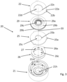
- FIG. 12 shows a schematic exploded view of the electromagnetic brake 20 according to the embodiment according to the invention figure 2 .
- the structure of the electromagnetic brake 20 and the arrangement of the associated components housing body 21, coil unit 26, armature disk 25, brake disk 29 and friction disk 22 relative to one another in the axial direction of the electromagnetic brake 20 can be seen clearly.
- the components mentioned are used for mounting on the central axis 33 aligned so that the holes 21h, 22d, 25c, 26c, 29c in all components are aligned concentrically, for example to mount a drive shaft.
- the components mentioned are then arranged concentrically in the housing body 21 with respect to the central axis 33, being aligned in their respective plane in such a way that the respective lug 22a, guide lug 25a, positioning lug 26a fits into the corresponding recess 21b, guide groove 21a and/or receptacle 21d of the housing body 21 can be used.
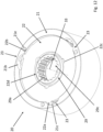
- FIG. 12 is a schematic perspective view of the case body 21 according to the embodiment of FIG figure 2 .
- the housing body 21 has a substantially hollow-cylindrical and ring-shaped shape with a circular base.
- the housing body 21 is designed in one piece here.
- the case body 21 has a first opening 21m at its end face opposite to the bottom 21k.
- the bottom 21k has a smaller second opening 21h compared to the first opening 21m.
- the aforementioned drive shaft (not shown) to be braked can be guided through the second opening 21h.
- the housing body 21 also has special shape details that are required for the assembly and function of the electromagnetic brake 20. These shape details are discussed in the following description.
- the first opening 21m extends to the casing wall 21i and is delimited by it.
- the housing body 21 has three recesses 21b in the casing wall 21i, each with receiving grooves 21c adjoining them.
- the recesses 21b are arranged on a web formed by the casing wall 21i and delimiting the receiving grooves 21c on the end face of the housing body 21.
- the receiving grooves 21c extend in sections circumferentially and at a distance from one another in the casing wall 21i of the housing body 21.
- This arrangement of the sectionwise extending receiving grooves 21c has the advantage that the final assembled position of the friction disk 22 in the housing body 21 can be easily adjusted by the position facing away from the recess 21b End of the receiving groove 21c can be predetermined and thus subsequent assembly steps can be simplified.
- the recesses 21b enable the friction disk 22 to be inserted into the receiving grooves 21c and, as a result, to produce the form-fitting bayonet-like connection 23 between the housing body 21 and the friction disk 22.
- the guide grooves 21a for guiding the armature disk 25 are arranged in such a way that the guide lugs 25a of the armature disk 25 can be inserted into the guide grooves 21a through the respective recess 21b.
- the armature disk 25 can be mounted on the shoulder 21f of the casing wall 21i of the housing body 21, which connects the base 21k with the casing wall 21i.
- the pole core 31 is ring-shaped and arranged in the housing body 21, in particular embedded in its wall or formed from it.
- the pole core 31 enclosing the opening 21h in the base 21k is spaced apart from the casing wall 21i or from the shoulder 21f of the housing body 21 in such a way that the coil unit 26 can be arranged between them.
- the pole core 31 and the housing body 21 share the same central axis 33.
- the pole core 31 is part of the housing body 21. Since the pole core 31 must be made of a magnetic material, the entire housing body 21 is made of a magnetic material in this exemplary embodiment manufactured.
- a circumferential groove 28 is arranged on the outer diameter of the pole core 31, in which the snap hooks 27 of the coil unit 26 can engage and be mounted. When a force occurs in the direction of the first opening 21m, the snap hooks 27 are then supported parallel to the central axis 33 on a web 28a delimiting the groove 28.
- the housing body 21 also has a receptacle 21d in its lateral wall 21i or in the step 21f, into which a positioning lug 26a of the coil unit 26 is inserted in order to secure the coil unit 26 relative to the housing body 21 against twisting.
- blind holes 21g in paragraph 21f are used to accommodate the compression springs 30. These are distributed evenly over the circumference of paragraph 21f. In the present exemplary embodiment, there are six blind holes 21g, so that all six compression springs 30 can be installed.
- a plurality of through bores 21e which extend parallel to the central axis 33 through the casing wall 21i of the housing body 21, are used to pass through the securing elements 100.
- the through bores 21e also each extend through the receiving groove 21c, which are used to receive the friction disk 22.
- the through holes 21e are unthreaded.
- the Figure 4b shows a schematic perspective representation of a further embodiment of the housing body 21.
- This embodiment differs from that in FIG Figure 4a illustrated embodiment in that only a single receiving groove 21c is made in the housing body 21 or its jacket wall 21i over the entire circumference, and instead of a single circumferential groove 28 or a circumferential web 28a for supporting the snap hooks 27, several of these are introduced circumferentially in sections and spaced apart from one another are.
- FIG. 12 is a schematic perspective view of the friction disc 22 according to the embodiment of FIG figure 2 .
- the friction disk 22 is designed to be rotationally symmetrical and comprises three approximately semicircular, outwardly directed lugs 22a, which are each arranged at an angle of 120° on the circumference of the friction disk 22.
- the number of lugs 22a can be varied, but should be at least two, so that the friction disk 22 can be prevented from being lifted out of the housing body 21 .
- a recess 22b is arranged in each of the lugs 22a, through which the securing elements 100 are inserted when the electromagnetic brake 20 is mounted on another component, in order to prevent the friction disc 22 from rotating about the central axis 33 . It is also conceivable that a recess 22b is not made in each nose 22a.
- the friction disk 22 has a hole in its center which is dimensioned in such a way that the drive shaft (not shown) to be braked can be passed through.
- the recesses 22c on the inner diameter of the friction disk 22 serve to improve the flow of force in the friction disk 22 and to grip the friction disk 22 in a precise position, for example by means of a robot gripper, and to precisely position the friction disk 22 in the housing body 21, even with narrow tolerances.
- the surface of the friction disk 22 is designed accordingly for optimal deceleration, at least on the side that is provided for braking contact with the brake disk 29 .
- FIG. 12 shows a schematic perspective representation of the armature disk 25 according to the embodiment according to FIG figure 2 .
- the armature disk 25 is designed to be rotationally symmetrical and comprises three approximately semicircular, outwardly directed guide lugs 25a, which are each arranged at an angle of 120° on the circumference of the armature disk 25.
- the three guide lugs 25a enable the armature disk 25 to be guided without tilting in the housing body 21 .
- the armature disk 25 has a hole 25c in its center which is dimensioned in such a way that the drive shaft (not shown) to be braked can be passed through.
- the recesses 25b on the inner diameter of the armature disk 25 serve to improve the flow of forces in the armature disk 25 and to grip the armature disk 25 in a precise position, for example by means of a robot gripper, and to precisely position the armature disk 25 in the housing body 21, even with narrow tolerances.
- the surface of the armature disk 25 is designed accordingly for optimal deceleration, at least on the side that faces the brake disk 29 .
- FIG. 12 is a schematic perspective view of the coil unit 26 according to the embodiment of FIG figure 2 .
- the coil unit 26 has a substantially ring-shaped geometry with a C-shaped cross section open towards the outside.
- the C-shaped cross-section is formed by an upper leg 26d extending essentially horizontally, a lower leg 26f extending essentially horizontally and one of the two legs 26d, 26f connecting and extending substantially at right angles to the legs 26d, 26f web 26e formed.
- the coil unit 26 has eight snap hooks 27 in this embodiment. However, the number of snap hooks 27 can be varied, taking into account the forces occurring in both axial directions.
- Each snap hook 27 is dimensioned and the material used is such that, when the coil unit 26 is installed in the housing body 21, it can be elastically deformed outwards when a force is applied, which acts parallel to the central axis 33 in the direction of the bottom 21k of the housing body 21, such that the snap hook 27 can engage in the groove 28.
- the snap hooks 27 are an integral part of the coil unit 26. However, it is also conceivable that the snap hooks 27 are separate components and are connected to the coil unit 26.
- the coil unit 26 also has an approximately semicircular positioning lug 26a, which serves to prevent rotation in the housing body 21.
- the positioning lug 26a in housing bodies 21 in which several grooves 28 are present in sections can serve to ensure that a snap hook 27 is positioned congruently with one of the grooves 28 when the coil unit 26 is assembled.
- the coil unit 26 is designed as a coil carrier and is suitable for accommodating one or more coils (not shown) that are necessary for generating a magnetic field.
- the coils are arranged or mounted in the outwardly open, C-shaped structure of the coil unit 26 .
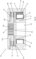
- FIGS 8a , 8b and 9 12 show schematic sectional views of the electromagnetic brake 20 according to the embodiment of the present invention figure 2 .
- the structure of the mounted electromagnetic brake 20 can be clearly seen.
- the housing body 21 has a recess dimensioned according to the dimensions of the coil unit 26 between its casing wall 21i and the pole core 31 .
- the recess is designed in such a way that when the coil unit 26 is installed, there is a clearance required for this purpose, and nevertheless the coil unit 26 is adequately fixed, in particular during the operation of the electromagnetic brake 20 is guaranteed.
- the snap hooks 27 of the coil unit 26 are mounted in the groove 28 and are supported on the web 28a of the housing body 21 (see figure 9 ). The coil unit 26 is therefore exclusively connected to the housing body 21 in a form-fitting manner.
- the armature disk 25 is arranged between the first opening 21m of the case body 21 and the coil unit 26 . So that the armature disk 25 can rest on the shoulder 21f, the upper leg 26d of the coil unit 26, which is directed towards the first opening 21m of the housing body 21, is correspondingly spaced from the shoulder 21f. By means of the pole core 31 excited by the coil unit 26, the tensile force can be generated, by means of which the armature disk 25 can be displaced axially away from the brake disk 29 in order to release the brake 20.
- the six compression springs 30 are each arranged in the blind holes 21g. In the Figures 8a and 8b only one blind hole 21g and one compression spring 30 are shown.
- the compression springs 30 are set up to displace the armature disk 25 axially toward the brake disk 29 through their compressive force for braking.
- the friction disk 22 is arranged between the end face of the housing body 21 and the brake disk 29 .
- the brake disk 29 arranged between the axially displaceable armature disk 25 and the friction disk 22 is designed to be rotatable about the central axis 33 and to be axially displaceable.
- the brake disc 29 has one or more brake pads 29b on both opposite sides in the area of its outer diameter. In this way, particularly in combination with the aforementioned surfaces on the friction disk 22 and/or the armature disk 25, optimal braking can be achieved.
- FIG 9 is the area from the Figures 8a and 8b shown enlarged, from which the installation situation of the coil unit 26 in the housing body 21 and the C-shaped cross section formed by the legs 26d, 26f and the web 26e can be clearly seen, which is open to the outside of the casing wall 21i.
- the snap hook 27 shown is an integral part of the coil unit 26, engages in the groove 28 and supports the coil unit 26 on the web 28a on the housing body 21.
- the coil unit 26 is thus positively connected to the housing body 21 by means of a snap connection 34 .
- the snap hook 27 is elastically deformed in the direction of the casing wall 21i of the housing body 21.
- the snap hooks 27 are bent back radially outwards during assembly of the coil unit 26 in order to then engage radially inwards in the groove 28 of the housing body 21 .
- the coil unit 26 has, in the region of the snap hooks 27, a slot-shaped recess running along the web 26e. The elastic deformation takes place due to a force which acts in particular parallel to the center axis 33 in the direction of the base 21k of the housing body 21 .
- the coil unit 26 is supported on a shoulder 26b on the bottom 21k of the housing body 21.
- the shoulder 26b creates a space between the coil unit 26 and the housing body 21 in the region of the diameter on which the snap hooks 27 are arranged.
- the space can therefore be used as a kind of spring deflection to press the leg 26f of the coil unit 26 facing the bottom 21k when it is installed outside the shoulder 26b around the shoulder 26b serving as a fulcrum in the direction of the bottom 21k of the housing body 21 and thus in this direction to bend so that the snap hooks 27 can engage more easily in the groove 28 of the housing body 21.
- the coil unit 26 is designed to be flexible or springy, so that the snap-in hooks 27 can be locked in place even if there are manufacturing inaccuracies.
- the figures 10 , 11 and 12 12 are schematic perspective views of the electromagnetic brake 20 according to the embodiment of the present invention figure 2 in different assembly states.
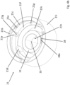
- the armature disk 25 is also shown installed in the housing body 21 .
- the armature disk 25 is inserted into the housing body 21 in such a way that each guide lug 25a of the armature disk 25 is guided in an associated guide groove 21a of the housing body 21 .
- the armature disk 25 is guided axially in the housing body 21 via the tongue and groove connection 32 formed in this way.
- the outer contour of the guide lugs 25a is preferably designed to correspond to the inner contour of the guide grooves 21a. However, sufficient play for an axial movement of the armature disk 25 is provided between the outer contour of the guide lugs 25a and the inner contour of the guide grooves 21a.
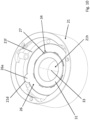
- the brake disc 29 and the friction disc 22 are also shown installed in the housing body 21 .
- the friction disk 22 is positively connected to the housing body 21 in a bayonet-like manner for this purpose.
- the lugs 22a of the friction disk 22 are guided through the recesses 21b into the receiving grooves 21c of the housing body 21 and are displaced in the latter in the direction of rotation.
- the friction disk 22 and the housing body 21 are thus rotated relative to one another about the central axis 33 .
- the three lugs 22a of the friction disk 22 and the recess 21b are no longer congruent axially, that is to say essentially parallel to the central axis 33 .
- the three connecting elements can then be guided through the through bores 21e and the correspondingly positioned recesses 22b on the lugs 22a of the friction disc 22, which in this case all also serve as securing elements 100 at the same time.
Landscapes
- Engineering & Computer Science (AREA)
- General Engineering & Computer Science (AREA)
- Mechanical Engineering (AREA)
- Physics & Mathematics (AREA)
- Electromagnetism (AREA)
- Power Engineering (AREA)
- Braking Arrangements (AREA)
- Carriers, Traveling Bodies, And Overhead Traveling Cranes (AREA)
- Snaps, Bayonet Connections, Set Pins, And Snap Rings (AREA)
Claims (10)
- Frein électromagnétique (20) comprenant un corps de boîtier (21) et un disque d'induit (25), le corps de boîtier (21) comprenant un noyau polaire (31), caractérisé en ce que le disque d'induit (25) est guidé axialement dans le corps de boîtier (21) par une liaison à rainure et languette (32), au moins une rainure de guidage (21a), de préférence trois rainures de guidage (21a), et au moins une languette de guidage associée (25a), de préférence trois languettes de guidage associées (25a), étant prévues, la rainure de guidage respective (21a) étant de préférence disposée dans le corps de boîtier (21).
- Frein électromagnétique (20) selon la revendication 1, caractérisé en ce qu'un disque de friction (22) est prévu qui est relié par complémentarité de formes, de préférence à la manière d'une fermeture à baïonnette (23), au corps de boîtier (21) et/ou est bloqué en rotation par rapport au corps de boîtier (21).
- Frein électromagnétique (20) selon la revendication 2, caractérisé en ce que le disque de friction (22) est bloqué en rotation par rapport au corps de boîtier (21) au moyen d'au moins un élément de blocage (100) et l'élément de blocage (100) est un élément de liaison qui est utilisé pour monter le frein électromagnétique (20) sur un composant.
- Frein électromagnétique (20) selon l'une des revendications précédentes, caractérisé en ce qu'une unité formant bobine (26) est prévue qui est reliée par complémentarité de formes au corps de boîtier (21) et/ou qui est bloquée en rotation par rapport au corps de boîtier. (21).
- Frein électromagnétique (20) selon la revendication 4, caractérisé en ce que l'unité formant bobine (26) est reliée par complémentarité de forme au corps de boîtier (21) au moyen d'une liaison par encliquetage (34), de préférence au moins un crochet d'encliquetage (27) de l'unité formant bobine (26) prenant appui sur une nervure (28a) du corps de boîtier (21).
- Frein électromagnétique (20) selon la revendication 4 ou 5, caractérisé en ce que l'unité formant bobine (26) est montée sur le corps de boîtier (21) de manière à ce que l'unité formant bobine (26) est mobile axialement par rapport au corps de boîtier (21) au niveau de la liaison par complémentarité de formes à ce dernier afin de simplifier le montage.
- Treuil (h) à frein électromagnétique (20) selon l'une des revendications précédentes.
- Procédé de montage d'un frein électromagnétique (20) selon l'une des revendications 1 à 6, caractérisé en ce que le disque d'induit (25) est inséré dans le corps de boîtier (21) pourvu d'un noyau polaire (31) de manière à ce qu'au moins une languette de guidage (25a) du disque d'induit (25) soit guidée dans une rainure de guidage associée (21a) du corps de boîtier (21).
- Procédé de montage d'un frein électromagnétique (20) selon la revendication 8, caractérisé en ce qu'un disque de friction (22) est inséré dans un évidement (21b) du corps de boîtier (21) et est amené en engagement, par un mouvement relatif dans le sens de rotation, avec le corps de boîtier (21) au moyen d'une rainure de réception (21c) attenante à l'évidement (21b), au moins un ergot (22a), de préférence trois ergots (22a), du disque de friction (22) et l'évidement (21b) n'étant plus congruents axialement après le mouvement relatif.
- Procédé de montage d'un frein électromagnétique (20) selon la revendication 8 ou 9, caractérisé en ce qu'une unité formant bobine (26) est inséré dans le corps de boîtier (21) de manière à ce qu'au moins une patte de positionnement (26a) de l'unité formant bobine (26) s'engage dans un logement correspondant (21d) du corps de boîtier (21) afin d'empêcher la rotation et/ou en que l'unité formant bobine (26) est reliée axialement par complémentarité de formes au corps de boîtier (21) au moyen d'une liaison par encliquetage (34).
Applications Claiming Priority (2)
| Application Number | Priority Date | Filing Date | Title |
|---|---|---|---|
| DE102019120043.1A DE102019120043A1 (de) | 2019-07-24 | 2019-07-24 | Elektromagnetische Bremse |
| PCT/EP2020/070400 WO2021013777A1 (fr) | 2019-07-24 | 2020-07-20 | Frein électromagnétique |
Publications (2)
| Publication Number | Publication Date |
|---|---|
| EP4004392A1 EP4004392A1 (fr) | 2022-06-01 |
| EP4004392B1 true EP4004392B1 (fr) | 2023-04-26 |
Family
ID=71894781
Family Applications (1)
| Application Number | Title | Priority Date | Filing Date |
|---|---|---|---|
| EP20749819.7A Active EP4004392B1 (fr) | 2019-07-24 | 2020-07-20 | Frein électromagnétique |
Country Status (6)
| Country | Link |
|---|---|
| US (1) | US12422005B2 (fr) |
| EP (1) | EP4004392B1 (fr) |
| JP (1) | JP7638954B2 (fr) |
| CN (1) | CN114270069A (fr) |
| DE (1) | DE102019120043A1 (fr) |
| WO (1) | WO2021013777A1 (fr) |
Families Citing this family (5)
| Publication number | Priority date | Publication date | Assignee | Title |
|---|---|---|---|---|
| DE102019120042A1 (de) * | 2019-07-24 | 2021-01-28 | Konecranes Global Corp. | Elektromagnetische Bremse |
| US12276312B2 (en) * | 2021-09-18 | 2025-04-15 | Altra Industrial Motion (shenzhen) Co., Ltd. | Magnetic yoke iron core and brake |
| KR102498761B1 (ko) * | 2022-09-05 | 2023-02-13 | 삼도산업전기(주) | 선로전환기의 마찰클러치 |
| WO2024223136A1 (fr) * | 2023-04-24 | 2024-10-31 | Sew-Eurodrive Gmbh & Co Kg | Ensemble de freinage, en particulier pour un moteur électrique, pour freiner un arbre |
| DE102024111216A1 (de) * | 2023-05-11 | 2024-11-14 | Sew-Eurodrive Gmbh & Co. Kg | Drahtführungselement, Bremse zum Abbremsen einer Welle und Bremsmotor mit Bremse |
Family Cites Families (29)
| Publication number | Priority date | Publication date | Assignee | Title |
|---|---|---|---|---|
| FR2135689A5 (fr) * | 1971-03-09 | 1972-12-22 | Potain Sa | |
| JPS5221387U (fr) * | 1975-08-01 | 1977-02-15 | ||
| JPS5836953B2 (ja) | 1975-08-07 | 1983-08-12 | メイトウサンギヨウ カブシキガイシヤ | シンキナリパ−ゼノセイゾウホウ |
| US4156478A (en) * | 1977-08-29 | 1979-05-29 | Warner Electric Brake & Clutch Company | Electrically released electromagnetic friction brake |
| JPS624735Y2 (fr) * | 1980-04-09 | 1987-02-03 | ||
| JPS56149134A (en) | 1980-04-21 | 1981-11-18 | Canon Inc | Data transmission system |
| FR2660381A1 (fr) * | 1990-03-30 | 1991-10-04 | Moulinex Sa | Frein electromagnetique destine a equiper un moteur. |
| JP2669748B2 (ja) | 1992-03-12 | 1997-10-29 | ファナック株式会社 | 電磁ブレーキ |
| DE19752543A1 (de) | 1997-11-27 | 1999-06-02 | Bosch Gmbh Robert | Magnetbremse und elektromechanische Bremsvorrichtung mit einer Magnetbremse |
| DE19838171B4 (de) | 1998-05-14 | 2006-04-06 | Sew-Eurodrive Gmbh & Co. Kg | Elektromotor mit Bremse |
| DE10049168C2 (de) * | 1999-10-19 | 2003-12-18 | Stromag Ag | Elektromagnetische Bremse |
| FI113505B (fi) * | 2000-01-17 | 2004-04-30 | Kci Kone Cranes Int Oy | Menetelmä ja sovitelma oikosulkumoottorin levyjarrun säätämiseksi |
| DE10006255A1 (de) * | 2000-02-11 | 2001-08-16 | Mayr Christian Gmbh & Co Kg | Elektromagnetische Bremse integriert in Treibscheibe |
| DE102006022491A1 (de) * | 2006-05-13 | 2008-01-17 | Chr. Mayr Gmbh & Co. Kg | Geräuschdämpfung Bremse |
| DE102006048558A1 (de) * | 2006-10-13 | 2008-04-17 | Deere & Company, Moline | Feststellbremse zum Feststellen mindestens eines drehbar gelagerten Bauteils gegenüber einem Gehäuse |
| DE102007028688A1 (de) | 2007-06-21 | 2008-12-24 | Jungheinrich Aktiengesellschaft | Automatische Federspeicherbremse für Flurförderzeug (FFZ) |
| DE202012000897U1 (de) * | 2012-01-31 | 2012-02-28 | Kendrion Magneta Gmbh | Federdruckbremse mit einem Magnetgehäuse |
| DE102012001701B3 (de) * | 2012-01-31 | 2013-03-14 | Kendrion Magneta Gmbh | Federdruckbremse mit einem Magnetgehäuse |
| JP5722363B2 (ja) * | 2013-02-07 | 2015-05-20 | ファナック株式会社 | 軸落下防止機能を有する電磁ブレーキ、電動機および機械 |
| KR101299558B1 (ko) | 2013-04-08 | 2013-08-23 | 주식회사 퓨트로닉 | 자화 잔류 방지 구조를 구비한 차륜 구동방식 전환 엑츄에이터용 전자식 브레이크 |
| DE102014101654B4 (de) * | 2014-02-11 | 2017-10-05 | Konecranes Global Corporation | Hebezeug mit Hysteresekupplung |
| CN105970896B (zh) | 2016-05-10 | 2018-02-13 | 武汉船用机械有限责任公司 | 一种海洋平台电动齿轮齿条升降机构 |
| JP6717711B2 (ja) * | 2016-08-30 | 2020-07-01 | ファナック株式会社 | 電磁ブレーキ |
| DE102017000845B4 (de) * | 2017-01-31 | 2022-06-02 | Sew-Eurodrive Gmbh & Co Kg | Elektromagnetisch betätigbare Bremsanordnung zum Abbremsen einer Welle und Elektromotor mit einer solchen Bremsanordnung |
| CN109990020B (zh) * | 2017-12-29 | 2020-11-20 | 比亚迪股份有限公司 | 盘式制动器以及具有其的车辆 |
| CN208295010U (zh) * | 2018-06-15 | 2018-12-28 | 成都超德创机电设备有限公司 | 一种带有磨损检测装置的电磁制动器 |
| CN109494327B (zh) * | 2018-11-09 | 2025-07-08 | 惠州市通晟智能科技有限公司 | 可拆卸旋接式供电机构及其便携式充气泵 |
| DE102019120041A1 (de) * | 2019-07-24 | 2021-01-28 | Konecranes Global Corp. | Elektromagnetische Bremse |
| DE102019120042A1 (de) | 2019-07-24 | 2021-01-28 | Konecranes Global Corp. | Elektromagnetische Bremse |
-
2019
- 2019-07-24 DE DE102019120043.1A patent/DE102019120043A1/de not_active Withdrawn
-
2020
- 2020-07-20 EP EP20749819.7A patent/EP4004392B1/fr active Active
- 2020-07-20 JP JP2022502223A patent/JP7638954B2/ja active Active
- 2020-07-20 WO PCT/EP2020/070400 patent/WO2021013777A1/fr not_active Ceased
- 2020-07-20 CN CN202080053375.8A patent/CN114270069A/zh active Pending
- 2020-07-20 US US17/597,800 patent/US12422005B2/en active Active
Also Published As
| Publication number | Publication date |
|---|---|
| JP2022542651A (ja) | 2022-10-06 |
| WO2021013777A1 (fr) | 2021-01-28 |
| EP4004392A1 (fr) | 2022-06-01 |
| US20220243775A1 (en) | 2022-08-04 |
| CN114270069A (zh) | 2022-04-01 |
| US12422005B2 (en) | 2025-09-23 |
| JP7638954B2 (ja) | 2025-03-04 |
| DE102019120043A1 (de) | 2021-01-28 |
Similar Documents
| Publication | Publication Date | Title |
|---|---|---|
| EP4004392B1 (fr) | Frein électromagnétique | |
| EP4004391B1 (fr) | Frein électromagnétique | |
| DE69707674T2 (de) | Elektromagnetisch lösbare sicherheits-reibungsbremse | |
| DE60024018T2 (de) | Mehrscheibenbremse für Flugzeuge | |
| DE19726674B4 (de) | Bremsscheibe | |
| WO2021013778A1 (fr) | Frein électromagnétique | |
| DD297215A5 (de) | Teilbelag-scheibenbremse | |
| EP1972823A1 (fr) | Disque de frein pour un frein à disque d'un véhicule et procédé de fabrication d'un tel disque de frein | |
| DE202017103961U1 (de) | Elektromagnetisch betätigbare Federkraftbremse und Antriebssystem | |
| DE102020216140A1 (de) | Bremsvorrichtung und Achsanordnung für ein Fahrzeug | |
| DE10160847A1 (de) | Betätigungsvorrichtung, insbesondere zur Betätigung von Sperrdifferentialen von Fahrzeugen | |
| EP1254323B1 (fr) | Frein electromagnetique integre dans une poulie motrice | |
| DE102006052767B4 (de) | Außenläufermotor mit Bremse | |
| DE29706124U1 (de) | Federdruckbremse | |
| DE19745775C2 (de) | Zentriereinrichtung an einem Bremssattel | |
| EP0953786A2 (fr) | Frein à ressort électromagnétique | |
| DE19819141C2 (de) | Elektromagnetische Federdruckbremse | |
| DE19814078B4 (de) | Elektromagnetische Federdruckbremse | |
| DE202011050872U1 (de) | Schalteinrichtung zur Steuerung einer Magnetschienenbremse | |
| WO2009021904A1 (fr) | Machine électrique avec un dispositif de fixation d'un stator | |
| EP0589408B1 (fr) | Dispositif pour le centrage et la prévention de la rotation d'un frein annulaire sur des véhicules | |
| DE102024104224B3 (de) | Bremseinrichtung für eine Bergbaumaschine | |
| WO2019052841A1 (fr) | Unité de freinage et unité d'entraînement pour un dispositif de transport de personnes et dispositif de transport de personnes | |
| DE202023001321U1 (de) | Federdruckbremse mit optimierter Schaltzeit | |
| WO2026082360A1 (fr) | Boîtier pour dispositif d'entraînement permettant d'entraîner un moyen de support d'un système d'ascenseur |
Legal Events
| Date | Code | Title | Description |
|---|---|---|---|
| STAA | Information on the status of an ep patent application or granted ep patent |
Free format text: STATUS: UNKNOWN |
|
| STAA | Information on the status of an ep patent application or granted ep patent |
Free format text: STATUS: THE INTERNATIONAL PUBLICATION HAS BEEN MADE |
|
| PUAI | Public reference made under article 153(3) epc to a published international application that has entered the european phase |
Free format text: ORIGINAL CODE: 0009012 |
|
| STAA | Information on the status of an ep patent application or granted ep patent |
Free format text: STATUS: REQUEST FOR EXAMINATION WAS MADE |
|
| 17P | Request for examination filed |
Effective date: 20220217 |
|
| AK | Designated contracting states |
Kind code of ref document: A1 Designated state(s): AL AT BE BG CH CY CZ DE DK EE ES FI FR GB GR HR HU IE IS IT LI LT LU LV MC MK MT NL NO PL PT RO RS SE SI SK SM TR |
|
| DAV | Request for validation of the european patent (deleted) | ||
| DAX | Request for extension of the european patent (deleted) | ||
| GRAP | Despatch of communication of intention to grant a patent |
Free format text: ORIGINAL CODE: EPIDOSNIGR1 |
|
| STAA | Information on the status of an ep patent application or granted ep patent |
Free format text: STATUS: GRANT OF PATENT IS INTENDED |
|
| INTG | Intention to grant announced |
Effective date: 20230124 |
|
| GRAS | Grant fee paid |
Free format text: ORIGINAL CODE: EPIDOSNIGR3 |
|
| GRAA | (expected) grant |
Free format text: ORIGINAL CODE: 0009210 |
|
| STAA | Information on the status of an ep patent application or granted ep patent |
Free format text: STATUS: THE PATENT HAS BEEN GRANTED |
|
| AK | Designated contracting states |
Kind code of ref document: B1 Designated state(s): AL AT BE BG CH CY CZ DE DK EE ES FI FR GB GR HR HU IE IS IT LI LT LU LV MC MK MT NL NO PL PT RO RS SE SI SK SM TR |
|
| REG | Reference to a national code |
Ref country code: GB Ref legal event code: FG4D Free format text: NOT ENGLISH |
|
| REG | Reference to a national code |
Ref country code: CH Ref legal event code: EP |
|
| REG | Reference to a national code |
Ref country code: DE Ref legal event code: R096 Ref document number: 502020003119 Country of ref document: DE |
|
| REG | Reference to a national code |
Ref country code: AT Ref legal event code: REF Ref document number: 1563032 Country of ref document: AT Kind code of ref document: T Effective date: 20230515 |
|
| REG | Reference to a national code |
Ref country code: IE Ref legal event code: FG4D Free format text: LANGUAGE OF EP DOCUMENT: GERMAN |
|
| P01 | Opt-out of the competence of the unified patent court (upc) registered |
Effective date: 20230527 |
|
| REG | Reference to a national code |
Ref country code: LT Ref legal event code: MG9D |
|
| REG | Reference to a national code |
Ref country code: NL Ref legal event code: MP Effective date: 20230426 |
|
| PG25 | Lapsed in a contracting state [announced via postgrant information from national office to epo] |
Ref country code: NL Free format text: LAPSE BECAUSE OF FAILURE TO SUBMIT A TRANSLATION OF THE DESCRIPTION OR TO PAY THE FEE WITHIN THE PRESCRIBED TIME-LIMIT Effective date: 20230426 |
|
| PG25 | Lapsed in a contracting state [announced via postgrant information from national office to epo] |
Ref country code: SE Free format text: LAPSE BECAUSE OF FAILURE TO SUBMIT A TRANSLATION OF THE DESCRIPTION OR TO PAY THE FEE WITHIN THE PRESCRIBED TIME-LIMIT Effective date: 20230426 Ref country code: PT Free format text: LAPSE BECAUSE OF FAILURE TO SUBMIT A TRANSLATION OF THE DESCRIPTION OR TO PAY THE FEE WITHIN THE PRESCRIBED TIME-LIMIT Effective date: 20230828 Ref country code: NO Free format text: LAPSE BECAUSE OF FAILURE TO SUBMIT A TRANSLATION OF THE DESCRIPTION OR TO PAY THE FEE WITHIN THE PRESCRIBED TIME-LIMIT Effective date: 20230726 Ref country code: ES Free format text: LAPSE BECAUSE OF FAILURE TO SUBMIT A TRANSLATION OF THE DESCRIPTION OR TO PAY THE FEE WITHIN THE PRESCRIBED TIME-LIMIT Effective date: 20230426 |
|
| PG25 | Lapsed in a contracting state [announced via postgrant information from national office to epo] |
Ref country code: RS Free format text: LAPSE BECAUSE OF FAILURE TO SUBMIT A TRANSLATION OF THE DESCRIPTION OR TO PAY THE FEE WITHIN THE PRESCRIBED TIME-LIMIT Effective date: 20230426 Ref country code: PL Free format text: LAPSE BECAUSE OF FAILURE TO SUBMIT A TRANSLATION OF THE DESCRIPTION OR TO PAY THE FEE WITHIN THE PRESCRIBED TIME-LIMIT Effective date: 20230426 Ref country code: LV Free format text: LAPSE BECAUSE OF FAILURE TO SUBMIT A TRANSLATION OF THE DESCRIPTION OR TO PAY THE FEE WITHIN THE PRESCRIBED TIME-LIMIT Effective date: 20230426 Ref country code: LT Free format text: LAPSE BECAUSE OF FAILURE TO SUBMIT A TRANSLATION OF THE DESCRIPTION OR TO PAY THE FEE WITHIN THE PRESCRIBED TIME-LIMIT Effective date: 20230426 Ref country code: IS Free format text: LAPSE BECAUSE OF FAILURE TO SUBMIT A TRANSLATION OF THE DESCRIPTION OR TO PAY THE FEE WITHIN THE PRESCRIBED TIME-LIMIT Effective date: 20230826 Ref country code: HR Free format text: LAPSE BECAUSE OF FAILURE TO SUBMIT A TRANSLATION OF THE DESCRIPTION OR TO PAY THE FEE WITHIN THE PRESCRIBED TIME-LIMIT Effective date: 20230426 Ref country code: GR Free format text: LAPSE BECAUSE OF FAILURE TO SUBMIT A TRANSLATION OF THE DESCRIPTION OR TO PAY THE FEE WITHIN THE PRESCRIBED TIME-LIMIT Effective date: 20230727 |
|
| PG25 | Lapsed in a contracting state [announced via postgrant information from national office to epo] |
Ref country code: FI Free format text: LAPSE BECAUSE OF FAILURE TO SUBMIT A TRANSLATION OF THE DESCRIPTION OR TO PAY THE FEE WITHIN THE PRESCRIBED TIME-LIMIT Effective date: 20230426 |
|
| PG25 | Lapsed in a contracting state [announced via postgrant information from national office to epo] |
Ref country code: SK Free format text: LAPSE BECAUSE OF FAILURE TO SUBMIT A TRANSLATION OF THE DESCRIPTION OR TO PAY THE FEE WITHIN THE PRESCRIBED TIME-LIMIT Effective date: 20230426 |
|
| REG | Reference to a national code |
Ref country code: DE Ref legal event code: R097 Ref document number: 502020003119 Country of ref document: DE |
|
| PG25 | Lapsed in a contracting state [announced via postgrant information from national office to epo] |
Ref country code: SM Free format text: LAPSE BECAUSE OF FAILURE TO SUBMIT A TRANSLATION OF THE DESCRIPTION OR TO PAY THE FEE WITHIN THE PRESCRIBED TIME-LIMIT Effective date: 20230426 Ref country code: SK Free format text: LAPSE BECAUSE OF FAILURE TO SUBMIT A TRANSLATION OF THE DESCRIPTION OR TO PAY THE FEE WITHIN THE PRESCRIBED TIME-LIMIT Effective date: 20230426 Ref country code: RO Free format text: LAPSE BECAUSE OF FAILURE TO SUBMIT A TRANSLATION OF THE DESCRIPTION OR TO PAY THE FEE WITHIN THE PRESCRIBED TIME-LIMIT Effective date: 20230426 Ref country code: EE Free format text: LAPSE BECAUSE OF FAILURE TO SUBMIT A TRANSLATION OF THE DESCRIPTION OR TO PAY THE FEE WITHIN THE PRESCRIBED TIME-LIMIT Effective date: 20230426 Ref country code: DK Free format text: LAPSE BECAUSE OF FAILURE TO SUBMIT A TRANSLATION OF THE DESCRIPTION OR TO PAY THE FEE WITHIN THE PRESCRIBED TIME-LIMIT Effective date: 20230426 Ref country code: CZ Free format text: LAPSE BECAUSE OF FAILURE TO SUBMIT A TRANSLATION OF THE DESCRIPTION OR TO PAY THE FEE WITHIN THE PRESCRIBED TIME-LIMIT Effective date: 20230426 |
|
| PG25 | Lapsed in a contracting state [announced via postgrant information from national office to epo] |
Ref country code: MC Free format text: LAPSE BECAUSE OF FAILURE TO SUBMIT A TRANSLATION OF THE DESCRIPTION OR TO PAY THE FEE WITHIN THE PRESCRIBED TIME-LIMIT Effective date: 20230426 |
|
| PG25 | Lapsed in a contracting state [announced via postgrant information from national office to epo] |
Ref country code: MC Free format text: LAPSE BECAUSE OF FAILURE TO SUBMIT A TRANSLATION OF THE DESCRIPTION OR TO PAY THE FEE WITHIN THE PRESCRIBED TIME-LIMIT Effective date: 20230426 |
|
| REG | Reference to a national code |
Ref country code: CH Ref legal event code: PL |
|
| PLBE | No opposition filed within time limit |
Free format text: ORIGINAL CODE: 0009261 |
|
| STAA | Information on the status of an ep patent application or granted ep patent |
Free format text: STATUS: NO OPPOSITION FILED WITHIN TIME LIMIT |
|
| REG | Reference to a national code |
Ref country code: BE Ref legal event code: MM Effective date: 20230731 |
|
| PG25 | Lapsed in a contracting state [announced via postgrant information from national office to epo] |
Ref country code: LU Free format text: LAPSE BECAUSE OF NON-PAYMENT OF DUE FEES Effective date: 20230720 |
|
| PG25 | Lapsed in a contracting state [announced via postgrant information from national office to epo] |
Ref country code: LU Free format text: LAPSE BECAUSE OF NON-PAYMENT OF DUE FEES Effective date: 20230720 |
|
| 26N | No opposition filed |
Effective date: 20240129 |
|
| REG | Reference to a national code |
Ref country code: IE Ref legal event code: MM4A |
|
| PG25 | Lapsed in a contracting state [announced via postgrant information from national office to epo] |
Ref country code: CH Free format text: LAPSE BECAUSE OF NON-PAYMENT OF DUE FEES Effective date: 20230731 |
|
| PG25 | Lapsed in a contracting state [announced via postgrant information from national office to epo] |
Ref country code: SI Free format text: LAPSE BECAUSE OF FAILURE TO SUBMIT A TRANSLATION OF THE DESCRIPTION OR TO PAY THE FEE WITHIN THE PRESCRIBED TIME-LIMIT Effective date: 20230426 |
|
| PG25 | Lapsed in a contracting state [announced via postgrant information from national office to epo] |
Ref country code: SI Free format text: LAPSE BECAUSE OF FAILURE TO SUBMIT A TRANSLATION OF THE DESCRIPTION OR TO PAY THE FEE WITHIN THE PRESCRIBED TIME-LIMIT Effective date: 20230426 Ref country code: IT Free format text: LAPSE BECAUSE OF FAILURE TO SUBMIT A TRANSLATION OF THE DESCRIPTION OR TO PAY THE FEE WITHIN THE PRESCRIBED TIME-LIMIT Effective date: 20230426 Ref country code: BE Free format text: LAPSE BECAUSE OF NON-PAYMENT OF DUE FEES Effective date: 20230731 |
|
| PG25 | Lapsed in a contracting state [announced via postgrant information from national office to epo] |
Ref country code: IE Free format text: LAPSE BECAUSE OF NON-PAYMENT OF DUE FEES Effective date: 20230720 |
|
| PG25 | Lapsed in a contracting state [announced via postgrant information from national office to epo] |
Ref country code: IE Free format text: LAPSE BECAUSE OF NON-PAYMENT OF DUE FEES Effective date: 20230720 |
|
| PG25 | Lapsed in a contracting state [announced via postgrant information from national office to epo] |
Ref country code: BG Free format text: LAPSE BECAUSE OF FAILURE TO SUBMIT A TRANSLATION OF THE DESCRIPTION OR TO PAY THE FEE WITHIN THE PRESCRIBED TIME-LIMIT Effective date: 20230426 |
|
| PG25 | Lapsed in a contracting state [announced via postgrant information from national office to epo] |
Ref country code: BG Free format text: LAPSE BECAUSE OF FAILURE TO SUBMIT A TRANSLATION OF THE DESCRIPTION OR TO PAY THE FEE WITHIN THE PRESCRIBED TIME-LIMIT Effective date: 20230426 |
|
| PG25 | Lapsed in a contracting state [announced via postgrant information from national office to epo] |
Ref country code: CY Free format text: LAPSE BECAUSE OF FAILURE TO SUBMIT A TRANSLATION OF THE DESCRIPTION OR TO PAY THE FEE WITHIN THE PRESCRIBED TIME-LIMIT; INVALID AB INITIO Effective date: 20200720 |
|
| PG25 | Lapsed in a contracting state [announced via postgrant information from national office to epo] |
Ref country code: HU Free format text: LAPSE BECAUSE OF FAILURE TO SUBMIT A TRANSLATION OF THE DESCRIPTION OR TO PAY THE FEE WITHIN THE PRESCRIBED TIME-LIMIT; INVALID AB INITIO Effective date: 20200720 |
|
| PGFP | Annual fee paid to national office [announced via postgrant information from national office to epo] |
Ref country code: DE Payment date: 20250722 Year of fee payment: 6 |
|
| PGFP | Annual fee paid to national office [announced via postgrant information from national office to epo] |
Ref country code: GB Payment date: 20250724 Year of fee payment: 6 |
|
| PGFP | Annual fee paid to national office [announced via postgrant information from national office to epo] |
Ref country code: AT Payment date: 20251020 Year of fee payment: 5 Ref country code: FR Payment date: 20250723 Year of fee payment: 6 |
|
| PG25 | Lapsed in a contracting state [announced via postgrant information from national office to epo] |
Ref country code: TR Free format text: LAPSE BECAUSE OF FAILURE TO SUBMIT A TRANSLATION OF THE DESCRIPTION OR TO PAY THE FEE WITHIN THE PRESCRIBED TIME-LIMIT Effective date: 20230426 |