EP4004423B1 - Système de surveillance et d'isolation de tuyau - Google Patents
Système de surveillance et d'isolation de tuyau Download PDFInfo
- Publication number
- EP4004423B1 EP4004423B1 EP20847055.9A EP20847055A EP4004423B1 EP 4004423 B1 EP4004423 B1 EP 4004423B1 EP 20847055 A EP20847055 A EP 20847055A EP 4004423 B1 EP4004423 B1 EP 4004423B1
- Authority
- EP
- European Patent Office
- Prior art keywords
- sealing head
- data acquisition
- pipe
- zone
- acquisition device
- Prior art date
- Legal status (The legal status is an assumption and is not a legal conclusion. Google has not performed a legal analysis and makes no representation as to the accuracy of the status listed.)
- Active
Links
Images


Classifications
-
- F—MECHANICAL ENGINEERING; LIGHTING; HEATING; WEAPONS; BLASTING
- F16—ENGINEERING ELEMENTS AND UNITS; GENERAL MEASURES FOR PRODUCING AND MAINTAINING EFFECTIVE FUNCTIONING OF MACHINES OR INSTALLATIONS; THERMAL INSULATION IN GENERAL
- F16L—PIPES; JOINTS OR FITTINGS FOR PIPES; SUPPORTS FOR PIPES, CABLES OR PROTECTIVE TUBING; MEANS FOR THERMAL INSULATION IN GENERAL
- F16L55/00—Devices or appurtenances for use in, or in connection with, pipes or pipe systems
- F16L55/10—Means for stopping flow in pipes or hoses
- F16L55/105—Closing devices introduced radially into the pipe or hose
Definitions
- the disclosure describes a pipe isolation and monitoring system for pipelines.
- the pipe isolation and monitoring system has a pipe isolation device used to seal a pipeline and a monitoring system to monitor operating conditions of the pipe isolation device locally and at remote sites and to provide information on operating conditions of the pipe isolation device.
- double block and bleed refers to the setting of two seals in a pipe with a bleed port located therebetween. If fluid leaks past the first seal, it is contained by the second seal and forced to exit the pipe through the bleed port.
- the double block and bleed apparatus when in the engaged position in a pipeline blocks fluid flow past the pipe isolation device to isolate the pipeline downstream of the pipe isolation device.
- the pipe isolation device allows maintenance and other operations for the pipeline to be performed downstream of the pipe isolation device.
- US 5924454A1 concerns a pipeline isolation tool for plugging a pipeline at a predetermined location.
- US 2009/114301A1 concerns a double block and bleed plug.
- Embodiments include conveying a pipe isolation device into the inlet section of a pipe, the pipe isolation device having a carrier, a primary sealing head, and a secondary sealing head; engaging the pipe isolation device to block flow through the pipeline; and measuring data values with a plurality of sensors with a means for transmitting acquired data to at least one data acquisition device.
- One or more embodiments may include the method of the preceding paragraph wherein the engaged pipe isolation device forms a live pipe zone sealed by the primary sealing head, an isolated zone disposed between the primary sealing head and the secondary sealing head, and a zero-energy zone disposed adjacent to the secondary sealing head.
- the plurality of sensors comprise a live pipe zone sensor, an isolated zone sensor, and a zero-energy zone sensor.
- One or more embodiments may include the method of any preceding paragraph wherein the data acquisition device is disposed locally to the pipe isolation device.
- One or more embodiments may include the method of any preceding paragraph wherein the data acquisition device is connected to the sensors by a wired connection.
- One or more embodiments may include the method of any preceding paragraph wherein the data acquisition device is disposed remotely from the pipe isolation device.
- One or more embodiments may include the method of any preceding paragraph wherein the data acquisition device is communicatively coupled to at least one edge device.
- One or more embodiments may include the method of any preceding paragraph wherein the data acquisition device is communicatively coupled to at least one edge device and the at least one edge device is communicatively coupled to at least one remote application.
- One or more embodiments may include the method of any preceding paragraph wherein the data acquisition device comprises a processing unit to process the acquired data, a non-transitory memory to record the acquired data, and a user interface to display the acquired data.
- One or more embodiments may include the method of any preceding paragraph wherein the acquired data is processed to determine if an operating condition of the pipe isolation device has reached a selected threshold.
- One or more embodiments may include the method of any preceding paragraph wherein the data acquisition device triggers an action when the operating condition has met the selected threshold.
- One or more embodiments may include the method of any preceding paragraph wherein the operating condition is a temperature of a fluid in an area of the pipeline.
- One or more embodiments may include the method of any preceding paragraph wherein the operating condition is an error in the functioning of the pipe isolation device.
- Embodiments include a carrier with a primary sealing head and a secondary sealing head, the primary sealing head and the secondary sealing head capable of creating a live zone, an isolated zone, and a zero-energy zone within a pipeline; a plurality of sensors configured to send acquired data; and at least one data acquisition device coupled to the plurality of sensors and configured to receive the acquired data.
- One or more embodiments may include the system of any preceding paragraph wherein the data acquisition device is communicatively coupled to the plurality of sensors with wires.
- One or more embodiments may include the system of any preceding paragraph wherein at least one edge device is communicatively coupled with the data acquisition device.
- One or more embodiments may include the system of any preceding paragraph wherein the at least one data acquisition device processes the acquired data from a live pipe sensor, an isolated zone sensor, and a zero-energy zone sensor and stores the acquired data in a non-transitory memory.
- One or more embodiments may include the system of any preceding paragraph wherein the at least one data acquisition device is at least one instrument communicatively coupled to the sensors and operable to upload to an information network, the at least one instrument with a user interface, a data acquisition component, and a data processing and store component.
- the at least one data acquisition device is at least one instrument communicatively coupled to the sensors and operable to upload to an information network, the at least one instrument with a user interface, a data acquisition component, and a data processing and store component.
- One or more embodiments may include the system of any preceding paragraph wherein the data acquisition device is at least one instrument communicatively coupled to the sensors with a user interface, a data acquisition component, a data processing and store component, and the at least one instrument is operable to upload to a remote application with configuration and administration modules.
- One or more embodiments may include the system of any preceding paragraph wherein the data acquisition device is configured to trigger an action if the acquired data meets a selected threshold.
- connection As used herein, the terms “connect”, “connection”, “connected”, “in connection with”, and “connecting” are used to mean “in direct connection with” or “in connection with via one or more elements”; and the term “set” is used to mean “one element” or “more than one element”. Further, the terms “couple”, “coupling”, “coupled”, “coupled together”, and “coupled with” are used to mean “directly coupled together” or “coupled together via one or more elements”. As used herein, the terms “up” and “down”; “upper” and “lower”; “top” and “bottom”; and other like terms indicating relative positions to a given point or element are utilized to more clearly describe some elements.
- the present disclosure generally relates to a pipe isolation and monitoring system for monitoring operating conditions of a pipe isolation device having multiple seals in a pipeline.
- the pipe isolation device may have a primary seal formed by primary sealing head and a secondary seal formed by a secondary sealing head.
- the pipe isolation device in an engaged position forms a live pipe zone on the pressurized side of the primary sealing head, an isolated, depressurized zone between the primary seal and the secondary seal, and a zero-energy zone adjacent to and downstream of the secondary sealing head.
- a monitoring system is used to monitor operating conditions of the pipe isolation device.
- the monitoring system includes sensors to measure values or parameters of the live pipe zone, isolated zone, and the zero-energy zone. Acquired data based on values measured by the sensors may be sent and processed by the monitoring system locally and/or remotely. For example, the acquired data from the sensors may be sent and processed to a local site in the location of the pipe isolation device and/or to a remote location with a device for accessing and/or processing the acquired data using an information network. The acquired data may be processed to analyze any deviation from set operating conditions.
- the monitoring system may generate alarms on-site and/or at a remote site if the monitoring system determines that values from the zones being measured deviate from the set operating conditions.
- maintenance and inspection of the pipe isolation device may be scheduled by the monitoring system. This identification of deviations from the set operating conditions may be used to more effectively schedule maintenance and inspection of the pipe isolation device, and to provide alarms on the operating conditions of the pipe isolation device.
- the pipe isolation and monitoring system of the present disclosure provides a system and method to achieve two or more seals inside the pipeline with the pipe isolation device and to monitor operating conditions of the pipe isolation device.
- the pressure in the space between the two seals or the isolated zone can be bled so that one seal is a primary seal and the other is a secondary backup seal.
- the pipe isolation device is set by traveling through a tapped access hole inside a fitting branch on the pipeline and product flow can continue through this fitting if a bypass line is set up.
- FIG 1 illustrates a pipe isolation and monitoring system 100 including a pipe isolation device 102 and a monitoring system 103 disposed in a pipeline 104, according to an embodiment of the present disclosure.
- Monitoring system 103 is configured to monitor operating conditions of the pipeline 104 and the pipe isolation device 102.
- An access connection to pipeline 104 is formed by an access fitting 106 disposed over a tapped access opening 107, shown in Figure 2 , inside the access fitting 106.
- the access fitting 106 may include a mating flange 108 that is attached to an access housing 110.
- Pipe isolation device 102 includes three main components: a primary sealing head 112, a secondary sealing head 114, and a control bar head 116.
- Control bar head 116 is a carrier for the sealing heads 112, 114 and is used to convey the sealing heads 112, 114.
- the two sealing heads 112, 114 can slide with respect to each other, and with respect to the control bar head 116 to place the pipe isolation device 102 in an engaged position, as shown in Figure 1 and Figure 2 .
- pipe isolation devices 102 may have a primary sealing head and a secondary sealing head that pivot with respect to one another to position the pipe isolation device to the engaged position in the pipeline 104.
- the primary sealing head 112 When the pipe isolation device 102 is in the engaged position shown in Figure 1 and Figure 2 , the primary sealing head 112 provides a primary seal to fluid in the pipeline 104 and the secondary sealing head 114 provides a secondary seal to form an isolated zone 126 between the primary seal and the secondary seal. Any leakage of fluid past the primary seal flows into the isolated zone 126.
- Control bar head 116 is attached to a control bar of an actuator, typically hydraulically powered, and translates through the access fitting 106 and the access opening 107 of the pipeline 104.
- Primary sealing head 112 includes a primary seal element 120 and the secondary sealing head 114 includes a secondary seal element 122.
- Primary seal element 120 and secondary seal element 122 may be made from elastomeric materials.
- Pipe isolation device 102 when in the engaged position establishes, as shown in Figure 2 , three zones in the pipeline 104: a live pipe zone 124, the isolated zone 126, and a zero-energy zone 128.
- Live pipe zone 124 is on the pressurized side of the primary sealing head 112
- the isolated zone 126 is between the primary sealing head 112 and the secondary sealing head 114
- zero-energy zone 128 is downstream of the secondary sealing head 114.
- Fluid that leaks past the primary seal element 120 flows into the isolated zone 126 and pressure from the fluid in the isolated zone 126 is bled out of the isolated zone 126.
- an embodiment of the present disclosure provides a bleed port 132 in the pipeline 104.
- Bleed port 132 extends through a wall of the pipeline 104 to form a passageway to the isolated zone 126 in the pipeline 104.
- a bleed joint 134 is formed over the bleed port 132.
- Bleed joint 134 may include a fitting, such as a valve.
- Bleed joint 134 may be formed by a T-joint over the bleed port 132.
- an internal passageway is connected to a hose which leads to a port on the tool's housing (not shown).
- This internal passageway passes through the primary sealing head 112 and into a port that goes through the control bar head 116 which then connects to the hose.
- the port (not shown) between the primary sealing head 112 and the control bar head 116 is only concentric once the pipe isolation device 102 is engaged.
- the port may be sealed with a face seal (not shown).
- a zero-energy port 136 extends through a wall of the pipeline 104 to form a passageway to the zero-energy zone 128 in the pipeline 104.
- a zero-energy joint 138 is formed over the zero-energy port 136.
- Zero-energy joint 138 may include a fitting, such as a valve.
- Zero-energy joint 138 may be formed by a T-joint over the zero-energy port 136. In the embodiment shown in Figure 1 and Figure 2 , a zero-energy joint 138 is fitted, and the pipeline 104 is tapped at the zero-energy port 136.
- the pipe isolation device 102 is shown in a retracted position. More specifically, the pipe isolation device 102 is shown partially extended through the access opening 107 of the pipeline 104 with the primary sealing head 112 and secondary sealing head 114 in retracted positions.
- An actuator rod 111 forms a part of an actuator for positioning the pipeline isolation device 102 from outside the pipeline 104 and into the access opening 107 when in the retracted position. Actuator rod continues a downward movement to position the pipe isolation device 102 in the engaged position shown in Figure 1 and Figure 2 .
- monitoring system 103 includes a live pipe sensor 142, an isolated zone sensor 144, and a zero-energy zone sensor 146 for measuring operating conditions of the pipe isolation device 102, including pressure and temperature of the fluid from the live pipe zone 124, isolated zone 126, and zero-energy zone 128.
- Sensors 142, 144, 146 may each be comprised of multiple physical sensors. In some embodiments, a single sensor may monitor conditions in two zones, such as in the live pipe zone 124 and the isolated zone 126, in the isolated zone 126 and the zero-energy zone 128, or in the live pipe zone 124 and the zero-energy zone 128. In some embodiments, sensors 142, 144, 146 may measure fluid flow rate.
- Sensors 142, 144, 146 generate data or values corresponding to operating conditions being measured.
- the location of sensors 142,144,146 may be external to the zones 124, 126, 128.
- sensors 142, 144, 146 may be integrated into the pipe isolation device 102.
- ultrasonic sensors and a camera may be used with the pipe isolation device 102 and may be located on the primary sealing head 112 to detect obstructions in the pipeline 104.
- a sensor for each sliding interface for the pipe isolation device 102 may be added to determine if deployment of the primary sealing head 112 and/or secondary sealing head 114 from a retracted position to a set position has begun and to confirm if the primary sealing head 112 and/or secondary sealing head 114 has reached the engaged or retracted position.
- a sensor monitors flow rate through access fitting 106, bypass housing, and/or main line before and after pipe isolation device 102 is engaged.
- the live pipe sensor 142 measures conditions of fluid in the live pipe zone 124.
- the live pipe sensor 142 may measure pressure and temperature of fluid from the live pipe zone 124 that has flowed into the access fitting 106 and mating flange 108.
- Access fitting 106 and mating flange 108 are fluidly coupled to the live pipe zone 124 via access opening 107 in pipeline 104.
- Isolated zone sensor 144 measures conditions of fluid in the isolated zone 126.
- the isolated zone sensor 144 may measure pressure and temperature of fluid from the isolated zone 126 that has flowed into bleed joint 134.
- Zero-energy zone sensor 146 measures conditions of fluid in the zero-energy zone 128.
- the zero-energy zone sensor 146 may measure pressure and temperature of fluid from the zero-energy zone 128 that has flowed through the zero-energy port 136 into the zero-energy joint 138.
- the zero-energy zone sensor 146 may measure hydrocarbon gas levels and other gas levels in the zero-energy zone 128.
- the zero-energy zone sensor may measure hydrocarbon gas level of fluid from the zero-energy zone 128.
- the monitoring system 103 may determine based on the data from the measured hydrocarbon gas level if the hydrocarbon gas level or other gas levels of the fluid in the zero-energy zone 128 has reached selected thresholds, including the lower explosive limit (LEL) for hydrocarbon gas. A selected threshold may be reached if an operating condition exceeds a selected value.
- LEL lower explosive limit
- Sensors 142, 144, 146 may be selected to measure a range of pipeline pressures and temperature ranges.
- the sensors may measure maximum allowable operating pressures and test pressures for the pipeline 104.
- Sensors 142, 144, 146 may be selected to comply with various standard setting and governmental bodies for various standards, including use of a component in a potentially explosive environment.
- the sensors 142, 144, 146 may be installed or removed from standard NPT pipe thread and have fluid compatibility with crude oil, water, natural gas, and gasoline.
- data acquisition device 150 is coupled to and acquires data from sensors 142, 144, 146.
- Data acquisition device 150 may be referred to as DAQ 150.
- Data acquisition device 150 may be locally positioned at the location of the pipe isolation device 102.
- data acquisition device 150 may be installed locally on the pipeline 104.
- data acquisition device 150 may record and monitor data acquired from the sensors 142, 144, 146.
- Data acquisition device 150 may have a processing unit for processing acquired data, a non-transitory memory for recording acquired data and other information, and a user interface, such as a human man interface (HMI) that may include a dashboard and/or screen.
- the HMI on the data acquisition device 150 may display values based on the acquired data from the sensors 142, 144, 146, including pressure, temperature, and other operating conditions of the zones 124, 126, and 128.
- HMI human man interface
- Data acquisition system 150 may determine based on the data from the sensors 142, 144, 146 if any condition value, including an operational condition, of fluid in one or more of the zones 124, 126, 128 has met selected thresholds. Selected thresholds may be met when a value reaches or exceeds the selected values. Data acquisition system 150 may identify errors including disconnection of one or more sensors 142, 144, 146 and improper working of the data acquisition system 150 and trigger an alarm when an error has been detected. Data acquisition device 150 is configured to notify its active status of monitoring sensors 142, 144, 146, including notification to an edge device 152 and/or a remote application 160, for example by sending a periodic message or "heartbeat" message to the edge device 152.
- Data acquisition system 150 may send a signal triggering or turning-on an alarm when a condition value has met the selected threshold, or an error has been detected by the data acquisition system 150.
- the alarm may be displayed on or audibly outputted by the HMI of the data acquisition device 150 or a device located remotely.
- Data acquisition device 150 may display charts and graphs based on the acquired data from sensors 142, 144, 146.
- sensors 142, 144, 146 may have a wired connection to the data acquisition device 150 and be configured to transmit acquired data to the data acquisition device 150 over the wired connection.
- Data acquisition device 150 may acquire data from multiple physical sensors forming each of the sensors 142, 144, 146. Each physical sensor may transmit data to the data acquisition device 150 over a separate communications channel.
- data acquisition device 150 may be battery powered and the data acquisition device 150 may provide power management, including communicating battery status and power level via the HMI for the data acquisition device 150 and/or other device at a remote location. Battery power for the data acquisition device 150 may be used because no wired-powered sources may be available locally to provide wired power to the data acquisition device 150.
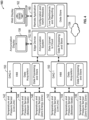
- Data acquisition device 150 is configured to transmit acquired data from the sensors 142, 144, 146 and processed data from the data acquisition device 150 to a remote location.
- data acquisition device 150 communicates to the remote location using the edge device 152 or Wi-Fi to connect to an information network, also referred to as the cloud 154.
- Edge device 152 may perform data processing of the sensor acquired data from sensors 142, 144, 146 or process other information based on the sensor acquired data.
- Edge device 152 may also include an annunciation system 156 providing information to users based on the sensor acquired data, including outputting on an annunciation display 158 alarms when values of the operating conditions meet selected threshold limits.
- Edge device 152 may include non-transitory memory for storing acquired data and/or monitoring data associated with the monitoring system 103. Acquired data may be uploaded to the cloud 154 by the edge device 152.
- Multiple data acquisition devices 150 may be wirelessly coupled to the edge device 152, as shown in Figure 4 .
- the pairing of a data acquisition device 150 with the edge device 152 may be configured with the remote application 160 via the web.
- Edge device 152 may act like an annunciation device and wirelessly communicate with various data acquisition devices 150 to display status of active alarms from all the data acquisition devices 150 paired with the edge device 152.
- Edge device 152 may upload data to the remote application 160 at a predefined frequency, and the edge device 152 may be connected to the web or other information network wirelessly, for example by a cellular or satellite connection.
- Edge device 152 may be battery powered and may include power management, including communicating the battery status.
- Remote application 160 may be used to remotely store acquired data and other monitoring data associated with the pipe isolation and monitoring system 100 in a cloud server and/or other non-transitory memory. Remote application 160 provides for data storage of acquired data and other monitoring data and generates live dashboards and reporting based on the data. Remote application 160 may include configuration and administration modules for managing and controlling the monitoring system 103, and a web display 162 may access and use the remote application 160.
- the configuration module may be used to manage inventories of data acquisition devices 150, edge devices 152, and the pairing of data acquisition devices 150 and edge devices 152.
- the configuration module may create job configurations, assign digital acquisition devices and download configurations.
- the configuration module may enable a user to tag a job with a project number, list parameters for a project, and identify data acquisition devices 150 to be used for the project. For each data acquisition device 150, the configuration module may enable a user to specify active channels and the type of data for each channel, frequency of data capture and upload, and operating ranges per sensor.
- Remote application 160 may be configured to allow a user to view the live status of the currently running jobs showing operating conditions for one or more pipe isolation devices 102 and associated values by selecting a job-number, and to view historical reports of various jobs.
- Data acquisition device 150 may be able to download settings and configurations from the remote application 160 via the Web using a Web browser or other connection to an information network.
- Data acquisition device 150 and/or remote application 160 may continuously record and monitor sensor acquired data and other monitoring data.
- Configuration and administration modules may be used to control the frequency of recording and monitoring sensor acquired data and other monitoring data.
- Data may be analyzed using the data acquisition device 150 and/or other device using the remote application 160 for any deviation from the set operating conditions and generate alarms locally on the data acquisition device 150 and/or locally on an annunciation device to warn users at the location of the pipe isolation device 102, and generate alarms to remote locations, such as the web display 162, via a web-interface or other network connection.
- Reports may be generated by the data acquisition device 150 and/or remote application 160.
- the remote application 160 may be accessed by remote devices to generate reports.
- the reports may include past data analyses for selected time periods and for one or more data acquisition devices 150.
- the reports may be per job.
- the reports may be generated and/or reviewed remotely via the web-interface or internet connection to a remote device, for example a web display 162.
- Remote application 160 may include other modules including: User Management to Add/ Update/ Delete Users and Add/ Update/ Delete User Permissions; Inventory Management to Add/ Update/ Delete DAQs, Add/ Update/ Delete Edge, and Base settings for DAQs and Edge; Download settings on DAQs and Edge; View Status of DAQs and Edge for Heartbeat, System utilization, Memory utilization, and Active channels.
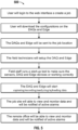
- the monitoring system 103 may provide in some embodiments a monitoring operation 500 as described in a flow chart shown in Figure 5 .
- a user may login to a web interface to create a job. This web interface may be connected to a remote application with administration and configuration modules. The user may then download the configurations on the DAQs and Edge. The DAQs and Edge configurations may then be sent to the job location, where field technicians may setup the DAQ and Edge. Field technicians may then run a startup test to make sure the sensors, DAQ, and Edge devices are working correctly. When the pipe monitoring device is activated, then the DAQ and Edge will start capturing, recording, analyzing, and uploading acquired data.
- the monitoring system allows users at the job site to view and monitor acquired data and be notified of any active alarms.
- office personnel at a remote location may view and monitor the data and be notified of any active alarms.
- users at the job site and office personnel at a remote location may simultaneously view and monitor the data and be notified of any active alarms.
- the monitoring system may initiate or trigger an action in response to an operating condition reaching a selected threshold, for example, scheduling maintenance and/or inspection of the pipe monitoring device or performing an activity within the pipe monitoring system and/or pipeline.
Landscapes
- Engineering & Computer Science (AREA)
- General Engineering & Computer Science (AREA)
- Mechanical Engineering (AREA)
- Pipeline Systems (AREA)
Claims (14)
- Procédé d'étanchéité et de surveillance d'une canalisation (104), comprenant :le transport d'un dispositif d'isolation de tuyau (102) dans la section d'entrée d'un tuyau, le dispositif d'isolation de tuyau (102) présentant un support (116), une tête d'étanchéité primaire (112) et une tête d'étanchéité secondaire (114) ;la mise en prise du dispositif d'isolation de tuyau (102) pour bloquer un écoulement à travers la canalisation (104), dans lequel la mise en prise du dispositif d'isolation de tuyau (102) forme une zone de tuyau sous tension (124) disposée sur un côté sous pression de la tête d'étanchéité primaire (112), une zone isolée (126) disposée entre la tête d'étanchéité primaire (112) et la tête d'étanchéité secondaire (114), et une zone à énergie nulle (128) disposée sur un côté aval de la tête d'étanchéité secondaire (114) ; etla mesure de valeurs de données avec une pluralité de capteurs avec un moyen de transmission de données acquises à au moins un dispositif d'acquisition de données (150), dans lequel la pluralité de capteurs comprend un capteur de zone de tuyau sous tension (142) configuré pour mesurer des conditions de fluide dans la zone de tuyau sous tension (124), un capteur de zone isolée (144) configuré pour mesurer les conditions de fluide dans la zone isolée (126), et un capteur de zone à énergie nulle (146) configuré pour mesurer des conditions de fluide dans la zone à énergie nulle (128).
- Procédé selon la revendication 1, dans lequel l'au moins un dispositif d'acquisition de données (150) est disposé localement sur le dispositif d'isolation de tuyau (102).
- Procédé selon la revendication 1, dans lequel l'au moins un dispositif d'acquisition de données (150) est couplé en communication à au moins un dispositif d'accès (152), et dans lequel l'au moins un dispositif d'acquisition de données (150) est connecté à la pluralité de capteurs par une connexion câblée.
- Procédé selon la revendication 1, dans lequel l'au moins un dispositif d'acquisition de données (150) est disposé à distance du dispositif d'isolation de tuyau (102).
- Procédé selon la revendication 1, dans lequel l'au moins un dispositif d'acquisition de données (150) est couplé en communication à au moins un dispositif d'accès (152) et l'au moins un dispositif d'accès (152) est couplé en communication à au moins une application distante (160).
- Procédé selon la revendication 1, dans lequel l'au moins un dispositif d'acquisition de données (150) comprend une unité de traitement pour traiter les données acquises, une mémoire non transitoire pour enregistrer les données acquises, et une interface utilisateur pour afficher les données acquises.
- Procédé selon la revendication 1, comprenant en outre le traitement des données acquises pour déterminer si une condition opérationnelle du dispositif d'isolation de tuyau (102) a atteint un seuil sélectionné, et facultativement ou préférentiellement
dans lequel l'au moins un dispositif d'acquisition de données (150) déclenche une action lorsque la condition opérationnelle a atteint le seuil sélectionné, et dans lequel(i) la condition opérationnelle est une température d'un fluide dans une zone de la canalisation (104), ou(ii) la condition opérationnelle est une erreur dans le fonctionnement du dispositif d'isolement de tuyau (102). - Procédé selon la revendication 1, dans lequel :le support (116), la tête d'étanchéité primaire (112), et la tête d'étanchéité secondaire (114) coulissent les uns par rapport aux autres ; etla mise en prise du dispositif d'isolation de tuyau (102) pour bloquer un écoulement à travers la canalisation (104) comprend une tige d'actionneur (111) translatant le support (116) pour son coulissement par rapport à la tête d'étanchéité primaire (112) et à la tête d'étanchéité secondaire (114) pour placer le dispositif d'isolation de tuyau (102) dans une position en prise.
- Système d'isolation et de surveillance de tuyau (103) pour une canalisation (104), comprenant :un support (116) doté d'une tête d'étanchéité primaire (112) et d'une tête d'étanchéité secondaire (114), la tête d'étanchéité primaire (112) et la tête d'étanchéité secondaire (114) étant aptes à créer une zone de tuyau sous tension (124), une zone isolée (126) disposée entre la tête d'étanchéité primaire (112) et la tête d'étanchéité secondaire (114), et une zone à énergie nulle (128) à l'intérieur d'une canalisation (104) ;une pluralité de capteurs configurés pour envoyer des données acquises, dans lequel la pluralité de capteurs comprend un capteur de zone de tuyau sous tension (142) configuré pour mesurer des conditions de fluide dans la zone de tuyau sous tension (124), un capteur de zone isolée (146) configuré pour mesurer des conditions de fluide dans la zone isolée (126), et un capteur de zone à énergie nulle (148) configuré pour mesurer des conditions de fluide dans la zone à énergie nulle (128) ; etau moins un dispositif d'acquisition de données (150) couplé à la pluralité de capteurs et configuré pour recevoir les données acquises.
- Système selon la revendication 9, dans lequel l'au moins un dispositif d'acquisition de données (150) comprend au moins un instrument couplé en communication aux capteurs et pouvant être téléchargé sur un réseau d'informations, l'au moins un instrument étant doté d'une interface utilisateur, d'un composant d'acquisition de données et d'un composant de traitement et de stockage de données.
- Système selon la revendication 9, dans lequel l'au moins un dispositif d'acquisition de données (150) comprend au moins un instrument couplé en communication aux capteurs avec une interface utilisateur, un composant d'acquisition de données et un composant de traitement et de stockage de données, et l'au moins un instrument peut être téléchargé sur une application distante avec des modules de configuration et d'administration.
- Système selon la revendication 9, comprenant en outre au moins un dispositif d'accès (152) couplé en communication à l'au moins un dispositif d'acquisition de données (150), dans lequel l'au moins un dispositif d'acquisition de données (150) est couplé en communication à la pluralité de capteurs avec des fils.
- Système selon la revendication 9, dans lequel :(i) l'au moins un dispositif d'acquisition de données (150) traite les données acquises à partir du capteur de zone de conduite sous tension (142), du capteur de zone isolée (146) et du capteur de zone à énergie nulle (148) et stocke les données acquises dans une mémoire non transitoire, ou(ii) l'au moins un dispositif d'acquisition de données (150) est configuré pour déclencher une action si les données acquises atteignent un seuil sélectionné.
- Système selon la revendication 9, dans lequel :le support (116), la tête d'étanchéité primaire (112), et la tête d'étanchéité secondaire (114) coulissent les uns par rapport aux autres ; etla tête d'étanchéité primaire (112) et la tête d'étanchéité secondaire (114) sont placées dans une position en prise lorsque le support (116), la tête d'étanchéité primaire (112), et la tête d'étanchéité secondaire (114) coulissent les uns par rapport aux autres.
Applications Claiming Priority (2)
| Application Number | Priority Date | Filing Date | Title |
|---|---|---|---|
| US201962880894P | 2019-07-31 | 2019-07-31 | |
| PCT/US2020/044191 WO2021022004A1 (fr) | 2019-07-31 | 2020-07-30 | Système de surveillance et d'isolation de tuyau |
Publications (3)
| Publication Number | Publication Date |
|---|---|
| EP4004423A1 EP4004423A1 (fr) | 2022-06-01 |
| EP4004423A4 EP4004423A4 (fr) | 2023-08-16 |
| EP4004423B1 true EP4004423B1 (fr) | 2025-04-23 |
Family
ID=74229016
Family Applications (1)
| Application Number | Title | Priority Date | Filing Date |
|---|---|---|---|
| EP20847055.9A Active EP4004423B1 (fr) | 2019-07-31 | 2020-07-30 | Système de surveillance et d'isolation de tuyau |
Country Status (5)
| Country | Link |
|---|---|
| US (1) | US20220275899A1 (fr) |
| EP (1) | EP4004423B1 (fr) |
| AU (1) | AU2020323946B2 (fr) |
| CA (1) | CA3149392A1 (fr) |
| WO (1) | WO2021022004A1 (fr) |
Families Citing this family (2)
| Publication number | Priority date | Publication date | Assignee | Title |
|---|---|---|---|---|
| EP3844431B1 (fr) * | 2018-08-30 | 2024-07-24 | Team Industrial Services Inc. | Dispositif d'isolation de conduite |
| US12035025B2 (en) * | 2022-07-08 | 2024-07-09 | I & EyeEnterprises, LLC | Modular camera |
Family Cites Families (38)
| Publication number | Priority date | Publication date | Assignee | Title |
|---|---|---|---|---|
| FR2122661A5 (fr) * | 1971-01-19 | 1972-09-01 | Elf Union | |
| GB1340431A (en) * | 1971-03-30 | 1973-12-12 | Pass & Co Ltd | Pipe line plugger |
| US3938544A (en) * | 1974-05-28 | 1976-02-17 | Bernaerts Henry J | Valve with heat transport monitor for leakage determining rate |
| DE3708471A1 (de) * | 1987-03-16 | 1988-09-29 | Kromschroeder Ag G | Verfahren und vorrichtung zur dichtheitskontrolle von zwei hintereinander in einer fluidleitung angeordneten ventilen |
| US5924454A (en) | 1996-01-29 | 1999-07-20 | Canadian Fracmaster Ltd. | Isolation tool |
| US6128946A (en) * | 1997-06-26 | 2000-10-10 | Crane Nuclear, Inc. | Method and apparatus for on-line detection of leaky emergency shut down or other valves |
| GB9823041D0 (en) * | 1998-10-22 | 1998-12-16 | British Gas Plc | Measuring leakage through ducts |
| CA2314573C (fr) * | 2000-01-13 | 2009-09-29 | Z.I. Probes, Inc. | Systeme et methode pour obtenir des donnees relativement a une installation |
| US6659133B2 (en) * | 2001-02-06 | 2003-12-09 | Larry R. Russell | Insertable line stopper plug for pipelines |
| US6598454B2 (en) * | 2001-07-30 | 2003-07-29 | Bs&B Safety Systems, Inc. | System and method for monitoring a pressurized system |
| US7525420B2 (en) * | 2001-11-02 | 2009-04-28 | Jerry L. McKinney | Environmental equipment alarm circuit verification system and method |
| DE10218830C1 (de) * | 2002-04-26 | 2003-12-18 | Siemens Ag | Diagnosesystem und -verfahren für ein Ventil |
| GB0213635D0 (en) * | 2002-06-13 | 2002-07-24 | Alpha Thames Ltd | Pressure protection system |
| US7817994B2 (en) * | 2004-09-20 | 2010-10-19 | Robert Bosch Gmbh | Secure control of wireless sensor network via the internet |
| DE102006049649B3 (de) * | 2006-10-20 | 2008-01-24 | Samson Ag | Verfahren und Anordnung zur Funktionsüberprüfung eines Ventils |
| US8725434B2 (en) * | 2006-12-29 | 2014-05-13 | Saudi Arabian Oil Company | Wellhead hips with automatic testing and self-diagnostics |
| US20100083738A1 (en) * | 2007-01-26 | 2010-04-08 | Est Group, Inc. | Test Plug and Method for Monitoring Downstream Conditions |
| US8356431B2 (en) * | 2007-04-13 | 2013-01-22 | Hart Communication Foundation | Scheduling communication frames in a wireless network |
| US7841364B2 (en) * | 2007-11-07 | 2010-11-30 | Tdw Delaware, Inc. | Double block and bleed plug |
| GB2466057B (en) * | 2008-12-11 | 2013-01-09 | Vetco Gray Controls Ltd | Pipeline protection system |
| US8525664B2 (en) * | 2009-08-03 | 2013-09-03 | Tyco Safety Products Canada Ltd | System and method for minimizing the amount of data being sent on a network for supervised security systems |
| US20130151020A1 (en) * | 2010-06-30 | 2013-06-13 | Metso Automation Oy | Measurement arrangement for field devices |
| US9625349B2 (en) * | 2012-02-29 | 2017-04-18 | Fisher Controls International Llc | Time-stamped emissions data collection for process control devices |
| US20140130878A1 (en) * | 2012-10-11 | 2014-05-15 | Luis Marinez | Intelligent valve network |
| US9841122B2 (en) * | 2014-09-09 | 2017-12-12 | Honeywell International Inc. | Gas valve with electronic valve proving system |
| US9645584B2 (en) * | 2014-09-17 | 2017-05-09 | Honeywell International Inc. | Gas valve with electronic health monitoring |
| US20160356665A1 (en) * | 2015-06-02 | 2016-12-08 | Umm Al-Qura University | Pipeline monitoring systems and methods |
| US10484237B2 (en) * | 2016-03-14 | 2019-11-19 | Accenture Global Solutions Limited | Platform for rapid prototyping of internet-enabled devices |
| US10616249B2 (en) * | 2016-03-31 | 2020-04-07 | Intel Corporation | Adaptive internet of things edge device security |
| US10240686B2 (en) * | 2016-08-18 | 2019-03-26 | Fisher Controls International Llc | Methods and apparatus for conducting in-service testing of pneumatic signal amplifiers |
| US10564062B2 (en) * | 2016-10-19 | 2020-02-18 | Honeywell International Inc. | Human-machine interface for gas valve |
| GB2557992B (en) * | 2016-12-21 | 2021-08-18 | Texecom Ltd | Frequency hopping spread spectrum communication in mesh networks |
| US10087063B2 (en) * | 2017-01-20 | 2018-10-02 | Afero, Inc. | Internet of things (IOT) system and method for monitoring and collecting data in a beverage dispensing system |
| US10419064B2 (en) * | 2017-03-31 | 2019-09-17 | Schweitzer Engineering Laboratories, Inc. | One-way broadcast communication |
| KR102715995B1 (ko) * | 2017-11-27 | 2024-10-15 | 생-고뱅 퍼포먼스 플라스틱스 코포레이션 | 누출 검출 시스템 및 이를 제조하고 사용하는 방법 |
| US20190294183A1 (en) * | 2018-03-26 | 2019-09-26 | Saudi Arabian Oil Company | High integrity protection system for hydrocarbon flow lines |
| EP3810972B1 (fr) * | 2018-06-22 | 2022-06-08 | TDW Delaware, Inc. | Bouchon d'isolation avec joint d'étanchéité activé |
| CA3077285A1 (fr) * | 2019-03-27 | 2020-09-27 | EnReach Hot Tap Services Inc. | Outil d`arret et purge double de secteur, joints pour celui-ci, et procedes d`isolement du secteur |
-
2020
- 2020-07-30 AU AU2020323946A patent/AU2020323946B2/en active Active
- 2020-07-30 EP EP20847055.9A patent/EP4004423B1/fr active Active
- 2020-07-30 US US17/631,500 patent/US20220275899A1/en active Pending
- 2020-07-30 CA CA3149392A patent/CA3149392A1/fr active Pending
- 2020-07-30 WO PCT/US2020/044191 patent/WO2021022004A1/fr not_active Ceased
Also Published As
| Publication number | Publication date |
|---|---|
| US20220275899A1 (en) | 2022-09-01 |
| AU2020323946A1 (en) | 2022-03-24 |
| EP4004423A4 (fr) | 2023-08-16 |
| CA3149392A1 (fr) | 2021-02-04 |
| WO2021022004A1 (fr) | 2021-02-04 |
| AU2020323946B2 (en) | 2025-12-18 |
| EP4004423A1 (fr) | 2022-06-01 |
Similar Documents
| Publication | Publication Date | Title |
|---|---|---|
| RU2657117C2 (ru) | Программируемый привод и способ контроля его рабочего состояния и надежности | |
| US7539548B2 (en) | Smart-control PLC based touch screen driven remote control panel for BOP control unit | |
| US8515880B2 (en) | Condition monitoring of an underwater facility | |
| EP2668367B1 (fr) | Surveillance du bon état d'un obturateur | |
| CA2756050C (fr) | Appareil pour systeme de protection haute integrite d'une tete de puits | |
| CN103576640B (zh) | 用于监测泵气蚀的系统和方法 | |
| US9416649B2 (en) | Method and system for determination of pipe location in blowout preventers | |
| KR102501000B1 (ko) | 케이블, 파이프 또는 와이어 트랜싯들을 위한 검사 시스템 | |
| US7895001B2 (en) | Subsea control system diagnosis | |
| EP4004423B1 (fr) | Système de surveillance et d'isolation de tuyau | |
| EP2818628B1 (fr) | Surveillance d'un filtre de fluide hydraulique | |
| CN109073089A (zh) | 用于机械系统的预测诊断的系统和方法 | |
| EP3532703B1 (fr) | Identification automatisée de dynamomètre | |
| US11840916B2 (en) | System and method for monitoring abandoned subsea wells with wet Christmas tree | |
| WO2016196948A1 (fr) | Détecteur de volume d'accumulateur utilisant une mesure optique | |
| EP4696909A2 (fr) | Systèmes et procédés de surveillance d'une soupape | |
| KR102650174B1 (ko) | 복합 환경 모니터링 및 제어 시스템과 그의 선내 환경 제어 방법 | |
| CA2823258A1 (fr) | Systeme hips pour tete de puits avec test automatique et autodiagnostic | |
| KR101149018B1 (ko) | 선박 상태 판정 및 제어 시스템 및 방법 | |
| CA2822052A1 (fr) | Appareil et procede pour systeme de protection a haute integrite de tetes de puits groupees | |
| WO2015126562A1 (fr) | Système d'obturateur anti-éruption possédant un dispositif de détection de position et de pression et procédés associés |
Legal Events
| Date | Code | Title | Description |
|---|---|---|---|
| STAA | Information on the status of an ep patent application or granted ep patent |
Free format text: STATUS: THE INTERNATIONAL PUBLICATION HAS BEEN MADE |
|
| PUAI | Public reference made under article 153(3) epc to a published international application that has entered the european phase |
Free format text: ORIGINAL CODE: 0009012 |
|
| STAA | Information on the status of an ep patent application or granted ep patent |
Free format text: STATUS: REQUEST FOR EXAMINATION WAS MADE |
|
| 17P | Request for examination filed |
Effective date: 20220228 |
|
| AK | Designated contracting states |
Kind code of ref document: A1 Designated state(s): AL AT BE BG CH CY CZ DE DK EE ES FI FR GB GR HR HU IE IS IT LI LT LU LV MC MK MT NL NO PL PT RO RS SE SI SK SM TR |
|
| DAV | Request for validation of the european patent (deleted) | ||
| DAX | Request for extension of the european patent (deleted) | ||
| A4 | Supplementary search report drawn up and despatched |
Effective date: 20230714 |
|
| RIC1 | Information provided on ipc code assigned before grant |
Ipc: F16L 55/124 20060101ALI20230710BHEP Ipc: F16L 55/11 20060101ALI20230710BHEP Ipc: F16L 55/10 20060101ALI20230710BHEP Ipc: F16L 55/105 20060101AFI20230710BHEP |
|
| GRAP | Despatch of communication of intention to grant a patent |
Free format text: ORIGINAL CODE: EPIDOSNIGR1 |
|
| STAA | Information on the status of an ep patent application or granted ep patent |
Free format text: STATUS: GRANT OF PATENT IS INTENDED |
|
| INTG | Intention to grant announced |
Effective date: 20241118 |
|
| GRAS | Grant fee paid |
Free format text: ORIGINAL CODE: EPIDOSNIGR3 |
|
| GRAA | (expected) grant |
Free format text: ORIGINAL CODE: 0009210 |
|
| STAA | Information on the status of an ep patent application or granted ep patent |
Free format text: STATUS: THE PATENT HAS BEEN GRANTED |
|
| AK | Designated contracting states |
Kind code of ref document: B1 Designated state(s): AL AT BE BG CH CY CZ DE DK EE ES FI FR GB GR HR HU IE IS IT LI LT LU LV MC MK MT NL NO PL PT RO RS SE SI SK SM TR |
|
| REG | Reference to a national code |
Ref country code: GB Ref legal event code: FG4D |
|
| REG | Reference to a national code |
Ref country code: CH Ref legal event code: EP |
|
| REG | Reference to a national code |
Ref country code: DE Ref legal event code: R096 Ref document number: 602020050112 Country of ref document: DE |
|
| REG | Reference to a national code |
Ref country code: IE Ref legal event code: FG4D |
|
| REG | Reference to a national code |
Ref country code: NL Ref legal event code: FP |
|
| PGFP | Annual fee paid to national office [announced via postgrant information from national office to epo] |
Ref country code: GB Payment date: 20250612 Year of fee payment: 6 |
|
| PGFP | Annual fee paid to national office [announced via postgrant information from national office to epo] |
Ref country code: NL Payment date: 20250618 Year of fee payment: 6 |
|
| REG | Reference to a national code |
Ref country code: AT Ref legal event code: MK05 Ref document number: 1788039 Country of ref document: AT Kind code of ref document: T Effective date: 20250423 |
|
| PG25 | Lapsed in a contracting state [announced via postgrant information from national office to epo] |
Ref country code: FI Free format text: LAPSE BECAUSE OF FAILURE TO SUBMIT A TRANSLATION OF THE DESCRIPTION OR TO PAY THE FEE WITHIN THE PRESCRIBED TIME-LIMIT Effective date: 20250423 Ref country code: ES Free format text: LAPSE BECAUSE OF FAILURE TO SUBMIT A TRANSLATION OF THE DESCRIPTION OR TO PAY THE FEE WITHIN THE PRESCRIBED TIME-LIMIT Effective date: 20250423 Ref country code: PT Free format text: LAPSE BECAUSE OF FAILURE TO SUBMIT A TRANSLATION OF THE DESCRIPTION OR TO PAY THE FEE WITHIN THE PRESCRIBED TIME-LIMIT Effective date: 20250825 |
|
| REG | Reference to a national code |
Ref country code: LT Ref legal event code: MG9D |
|
| PG25 | Lapsed in a contracting state [announced via postgrant information from national office to epo] |
Ref country code: NO Free format text: LAPSE BECAUSE OF FAILURE TO SUBMIT A TRANSLATION OF THE DESCRIPTION OR TO PAY THE FEE WITHIN THE PRESCRIBED TIME-LIMIT Effective date: 20250723 Ref country code: GR Free format text: LAPSE BECAUSE OF FAILURE TO SUBMIT A TRANSLATION OF THE DESCRIPTION OR TO PAY THE FEE WITHIN THE PRESCRIBED TIME-LIMIT Effective date: 20250724 |
|
| PG25 | Lapsed in a contracting state [announced via postgrant information from national office to epo] |
Ref country code: PL Free format text: LAPSE BECAUSE OF FAILURE TO SUBMIT A TRANSLATION OF THE DESCRIPTION OR TO PAY THE FEE WITHIN THE PRESCRIBED TIME-LIMIT Effective date: 20250423 |
|
| PG25 | Lapsed in a contracting state [announced via postgrant information from national office to epo] |
Ref country code: BG Free format text: LAPSE BECAUSE OF FAILURE TO SUBMIT A TRANSLATION OF THE DESCRIPTION OR TO PAY THE FEE WITHIN THE PRESCRIBED TIME-LIMIT Effective date: 20250423 |
|
| PG25 | Lapsed in a contracting state [announced via postgrant information from national office to epo] |
Ref country code: HR Free format text: LAPSE BECAUSE OF FAILURE TO SUBMIT A TRANSLATION OF THE DESCRIPTION OR TO PAY THE FEE WITHIN THE PRESCRIBED TIME-LIMIT Effective date: 20250423 |
|
| PG25 | Lapsed in a contracting state [announced via postgrant information from national office to epo] |
Ref country code: AT Free format text: LAPSE BECAUSE OF FAILURE TO SUBMIT A TRANSLATION OF THE DESCRIPTION OR TO PAY THE FEE WITHIN THE PRESCRIBED TIME-LIMIT Effective date: 20250423 |
|
| PG25 | Lapsed in a contracting state [announced via postgrant information from national office to epo] |
Ref country code: RS Free format text: LAPSE BECAUSE OF FAILURE TO SUBMIT A TRANSLATION OF THE DESCRIPTION OR TO PAY THE FEE WITHIN THE PRESCRIBED TIME-LIMIT Effective date: 20250723 |
|
| PG25 | Lapsed in a contracting state [announced via postgrant information from national office to epo] |
Ref country code: IS Free format text: LAPSE BECAUSE OF FAILURE TO SUBMIT A TRANSLATION OF THE DESCRIPTION OR TO PAY THE FEE WITHIN THE PRESCRIBED TIME-LIMIT Effective date: 20250823 |
|
| PG25 | Lapsed in a contracting state [announced via postgrant information from national office to epo] |
Ref country code: LV Free format text: LAPSE BECAUSE OF FAILURE TO SUBMIT A TRANSLATION OF THE DESCRIPTION OR TO PAY THE FEE WITHIN THE PRESCRIBED TIME-LIMIT Effective date: 20250423 |
|
| PG25 | Lapsed in a contracting state [announced via postgrant information from national office to epo] |
Ref country code: DK Free format text: LAPSE BECAUSE OF FAILURE TO SUBMIT A TRANSLATION OF THE DESCRIPTION OR TO PAY THE FEE WITHIN THE PRESCRIBED TIME-LIMIT Effective date: 20250423 Ref country code: SM Free format text: LAPSE BECAUSE OF FAILURE TO SUBMIT A TRANSLATION OF THE DESCRIPTION OR TO PAY THE FEE WITHIN THE PRESCRIBED TIME-LIMIT Effective date: 20250423 |
|
| PG25 | Lapsed in a contracting state [announced via postgrant information from national office to epo] |
Ref country code: CZ Free format text: LAPSE BECAUSE OF FAILURE TO SUBMIT A TRANSLATION OF THE DESCRIPTION OR TO PAY THE FEE WITHIN THE PRESCRIBED TIME-LIMIT Effective date: 20250423 |
|
| PG25 | Lapsed in a contracting state [announced via postgrant information from national office to epo] |
Ref country code: EE Free format text: LAPSE BECAUSE OF FAILURE TO SUBMIT A TRANSLATION OF THE DESCRIPTION OR TO PAY THE FEE WITHIN THE PRESCRIBED TIME-LIMIT Effective date: 20250423 |
|
| REG | Reference to a national code |
Ref country code: DE Ref legal event code: R097 Ref document number: 602020050112 Country of ref document: DE |
|
| PG25 | Lapsed in a contracting state [announced via postgrant information from national office to epo] |
Ref country code: RO Free format text: LAPSE BECAUSE OF FAILURE TO SUBMIT A TRANSLATION OF THE DESCRIPTION OR TO PAY THE FEE WITHIN THE PRESCRIBED TIME-LIMIT Effective date: 20250423 Ref country code: SK Free format text: LAPSE BECAUSE OF FAILURE TO SUBMIT A TRANSLATION OF THE DESCRIPTION OR TO PAY THE FEE WITHIN THE PRESCRIBED TIME-LIMIT Effective date: 20250423 |
|
| PG25 | Lapsed in a contracting state [announced via postgrant information from national office to epo] |
Ref country code: IT Free format text: LAPSE BECAUSE OF FAILURE TO SUBMIT A TRANSLATION OF THE DESCRIPTION OR TO PAY THE FEE WITHIN THE PRESCRIBED TIME-LIMIT Effective date: 20250423 |
|
| REG | Reference to a national code |
Ref country code: DE Ref legal event code: R119 Ref document number: 602020050112 Country of ref document: DE |
|
| REG | Reference to a national code |
Ref country code: CH Ref legal event code: H13 Free format text: ST27 STATUS EVENT CODE: U-0-0-H10-H13 (AS PROVIDED BY THE NATIONAL OFFICE) Effective date: 20260224 |
|
| PLBE | No opposition filed within time limit |
Free format text: ORIGINAL CODE: 0009261 |
|
| STAA | Information on the status of an ep patent application or granted ep patent |
Free format text: STATUS: NO OPPOSITION FILED WITHIN TIME LIMIT |
|
| REG | Reference to a national code |
Ref country code: CH Ref legal event code: L10 Free format text: ST27 STATUS EVENT CODE: U-0-0-L10-L00 (AS PROVIDED BY THE NATIONAL OFFICE) Effective date: 20260304 |
|
| PG25 | Lapsed in a contracting state [announced via postgrant information from national office to epo] |
Ref country code: LU Free format text: LAPSE BECAUSE OF NON-PAYMENT OF DUE FEES Effective date: 20250730 |
|
| REG | Reference to a national code |
Ref country code: BE Ref legal event code: MM Effective date: 20250731 |
|
| 26N | No opposition filed |
Effective date: 20260126 |
|
| PG25 | Lapsed in a contracting state [announced via postgrant information from national office to epo] |
Ref country code: DE Free format text: LAPSE BECAUSE OF NON-PAYMENT OF DUE FEES Effective date: 20260203 |
|
| PG25 | Lapsed in a contracting state [announced via postgrant information from national office to epo] |
Ref country code: BE Free format text: LAPSE BECAUSE OF NON-PAYMENT OF DUE FEES Effective date: 20250731 |
|
| PG25 | Lapsed in a contracting state [announced via postgrant information from national office to epo] |
Ref country code: FR Free format text: LAPSE BECAUSE OF NON-PAYMENT OF DUE FEES Effective date: 20250731 |
|
| PG25 | Lapsed in a contracting state [announced via postgrant information from national office to epo] |
Ref country code: CH Free format text: LAPSE BECAUSE OF NON-PAYMENT OF DUE FEES Effective date: 20250731 |