EP4004424B1 - Isolierstruktur für ein flüssigkeitsrohr - Google Patents
Isolierstruktur für ein flüssigkeitsrohr Download PDFInfo
- Publication number
- EP4004424B1 EP4004424B1 EP20753996.6A EP20753996A EP4004424B1 EP 4004424 B1 EP4004424 B1 EP 4004424B1 EP 20753996 A EP20753996 A EP 20753996A EP 4004424 B1 EP4004424 B1 EP 4004424B1
- Authority
- EP
- European Patent Office
- Prior art keywords
- insulating structure
- wall
- pipe
- protrusion
- insulating
- Prior art date
- Legal status (The legal status is an assumption and is not a legal conclusion. Google has not performed a legal analysis and makes no representation as to the accuracy of the status listed.)
- Active
Links
Images




Classifications
-
- F—MECHANICAL ENGINEERING; LIGHTING; HEATING; WEAPONS; BLASTING
- F16—ENGINEERING ELEMENTS AND UNITS; GENERAL MEASURES FOR PRODUCING AND MAINTAINING EFFECTIVE FUNCTIONING OF MACHINES OR INSTALLATIONS; THERMAL INSULATION IN GENERAL
- F16L—PIPES; JOINTS OR FITTINGS FOR PIPES; SUPPORTS FOR PIPES, CABLES OR PROTECTIVE TUBING; MEANS FOR THERMAL INSULATION IN GENERAL
- F16L59/00—Thermal insulation in general
- F16L59/12—Arrangements for supporting insulation from the wall or body insulated, e.g. by means of spacers between pipe and heat-insulating material; Arrangements specially adapted for supporting insulated bodies
-
- B—PERFORMING OPERATIONS; TRANSPORTING
- B32—LAYERED PRODUCTS
- B32B—LAYERED PRODUCTS, i.e. PRODUCTS BUILT-UP OF STRATA OF FLAT OR NON-FLAT, e.g. CELLULAR OR HONEYCOMB, FORM
- B32B1/00—Layered products having a non-planar shape
- B32B1/08—Tubular products
-
- B—PERFORMING OPERATIONS; TRANSPORTING
- B32—LAYERED PRODUCTS
- B32B—LAYERED PRODUCTS, i.e. PRODUCTS BUILT-UP OF STRATA OF FLAT OR NON-FLAT, e.g. CELLULAR OR HONEYCOMB, FORM
- B32B3/00—Layered products comprising a layer with external or internal discontinuities or unevennesses, or a layer of non-planar shape; Layered products comprising a layer having particular features of form
- B32B3/26—Layered products comprising a layer with external or internal discontinuities or unevennesses, or a layer of non-planar shape; Layered products comprising a layer having particular features of form characterised by a particular shape of the outline of the cross-section of a continuous layer; characterised by a layer with cavities or internal voids ; characterised by an apertured layer
- B32B3/30—Layered products comprising a layer with external or internal discontinuities or unevennesses, or a layer of non-planar shape; Layered products comprising a layer having particular features of form characterised by a particular shape of the outline of the cross-section of a continuous layer; characterised by a layer with cavities or internal voids ; characterised by an apertured layer characterised by a layer formed with recesses or projections, e.g. hollows, grooves, protuberances, ribs
-
- B—PERFORMING OPERATIONS; TRANSPORTING
- B32—LAYERED PRODUCTS
- B32B—LAYERED PRODUCTS, i.e. PRODUCTS BUILT-UP OF STRATA OF FLAT OR NON-FLAT, e.g. CELLULAR OR HONEYCOMB, FORM
- B32B5/00—Layered products characterised by the non- homogeneity or physical structure, i.e. comprising a fibrous, filamentary, particulate or foam layer; Layered products characterised by having a layer differing constitutionally or physically in different parts
- B32B5/02—Layered products characterised by the non- homogeneity or physical structure, i.e. comprising a fibrous, filamentary, particulate or foam layer; Layered products characterised by having a layer differing constitutionally or physically in different parts characterised by structural features of a fibrous or filamentary layer
- B32B5/022—Non-woven fabric
-
- B—PERFORMING OPERATIONS; TRANSPORTING
- B32—LAYERED PRODUCTS
- B32B—LAYERED PRODUCTS, i.e. PRODUCTS BUILT-UP OF STRATA OF FLAT OR NON-FLAT, e.g. CELLULAR OR HONEYCOMB, FORM
- B32B5/00—Layered products characterised by the non- homogeneity or physical structure, i.e. comprising a fibrous, filamentary, particulate or foam layer; Layered products characterised by having a layer differing constitutionally or physically in different parts
- B32B5/14—Layered products characterised by the non- homogeneity or physical structure, i.e. comprising a fibrous, filamentary, particulate or foam layer; Layered products characterised by having a layer differing constitutionally or physically in different parts characterised by a layer differing constitutionally or physically in different parts, e.g. denser near its faces
-
- F—MECHANICAL ENGINEERING; LIGHTING; HEATING; WEAPONS; BLASTING
- F16—ENGINEERING ELEMENTS AND UNITS; GENERAL MEASURES FOR PRODUCING AND MAINTAINING EFFECTIVE FUNCTIONING OF MACHINES OR INSTALLATIONS; THERMAL INSULATION IN GENERAL
- F16L—PIPES; JOINTS OR FITTINGS FOR PIPES; SUPPORTS FOR PIPES, CABLES OR PROTECTIVE TUBING; MEANS FOR THERMAL INSULATION IN GENERAL
- F16L55/00—Devices or appurtenances for use in, or in connection with, pipes or pipe systems
- F16L55/02—Energy absorbers; Noise absorbers
- F16L55/033—Noise absorbers
- F16L55/0336—Noise absorbers by means of sound-absorbing materials
-
- F—MECHANICAL ENGINEERING; LIGHTING; HEATING; WEAPONS; BLASTING
- F16—ENGINEERING ELEMENTS AND UNITS; GENERAL MEASURES FOR PRODUCING AND MAINTAINING EFFECTIVE FUNCTIONING OF MACHINES OR INSTALLATIONS; THERMAL INSULATION IN GENERAL
- F16L—PIPES; JOINTS OR FITTINGS FOR PIPES; SUPPORTS FOR PIPES, CABLES OR PROTECTIVE TUBING; MEANS FOR THERMAL INSULATION IN GENERAL
- F16L59/00—Thermal insulation in general
- F16L59/06—Arrangements using an air layer or vacuum
- F16L59/075—Arrangements using an air layer or vacuum the air layer or the vacuum being delimited by longitudinal channels distributed around the circumference of a tube
-
- F—MECHANICAL ENGINEERING; LIGHTING; HEATING; WEAPONS; BLASTING
- F16—ENGINEERING ELEMENTS AND UNITS; GENERAL MEASURES FOR PRODUCING AND MAINTAINING EFFECTIVE FUNCTIONING OF MACHINES OR INSTALLATIONS; THERMAL INSULATION IN GENERAL
- F16L—PIPES; JOINTS OR FITTINGS FOR PIPES; SUPPORTS FOR PIPES, CABLES OR PROTECTIVE TUBING; MEANS FOR THERMAL INSULATION IN GENERAL
- F16L55/00—Devices or appurtenances for use in, or in connection with, pipes or pipe systems
- F16L55/02—Energy absorbers; Noise absorbers
- F16L55/033—Noise absorbers
- F16L55/0335—Noise absorbers by means of external rings
-
- F—MECHANICAL ENGINEERING; LIGHTING; HEATING; WEAPONS; BLASTING
- F16—ENGINEERING ELEMENTS AND UNITS; GENERAL MEASURES FOR PRODUCING AND MAINTAINING EFFECTIVE FUNCTIONING OF MACHINES OR INSTALLATIONS; THERMAL INSULATION IN GENERAL
- F16L—PIPES; JOINTS OR FITTINGS FOR PIPES; SUPPORTS FOR PIPES, CABLES OR PROTECTIVE TUBING; MEANS FOR THERMAL INSULATION IN GENERAL
- F16L59/00—Thermal insulation in general
- F16L59/02—Shape or form of insulating materials, with or without coverings integral with the insulating materials
- F16L59/021—Shape or form of insulating materials, with or without coverings integral with the insulating materials comprising a single piece or sleeve, e.g. split sleeves; consisting of two half sleeves; comprising more than two segments
- F16L59/022—Shape or form of insulating materials, with or without coverings integral with the insulating materials comprising a single piece or sleeve, e.g. split sleeves; consisting of two half sleeves; comprising more than two segments with a single slit
-
- F—MECHANICAL ENGINEERING; LIGHTING; HEATING; WEAPONS; BLASTING
- F16—ENGINEERING ELEMENTS AND UNITS; GENERAL MEASURES FOR PRODUCING AND MAINTAINING EFFECTIVE FUNCTIONING OF MACHINES OR INSTALLATIONS; THERMAL INSULATION IN GENERAL
- F16L—PIPES; JOINTS OR FITTINGS FOR PIPES; SUPPORTS FOR PIPES, CABLES OR PROTECTIVE TUBING; MEANS FOR THERMAL INSULATION IN GENERAL
- F16L59/00—Thermal insulation in general
- F16L59/04—Arrangements using dry fillers, e.g. using slag wool
-
- F—MECHANICAL ENGINEERING; LIGHTING; HEATING; WEAPONS; BLASTING
- F16—ENGINEERING ELEMENTS AND UNITS; GENERAL MEASURES FOR PRODUCING AND MAINTAINING EFFECTIVE FUNCTIONING OF MACHINES OR INSTALLATIONS; THERMAL INSULATION IN GENERAL
- F16L—PIPES; JOINTS OR FITTINGS FOR PIPES; SUPPORTS FOR PIPES, CABLES OR PROTECTIVE TUBING; MEANS FOR THERMAL INSULATION IN GENERAL
- F16L59/00—Thermal insulation in general
- F16L59/08—Means for preventing radiation, e.g. with metal foil
-
- F—MECHANICAL ENGINEERING; LIGHTING; HEATING; WEAPONS; BLASTING
- F16—ENGINEERING ELEMENTS AND UNITS; GENERAL MEASURES FOR PRODUCING AND MAINTAINING EFFECTIVE FUNCTIONING OF MACHINES OR INSTALLATIONS; THERMAL INSULATION IN GENERAL
- F16L—PIPES; JOINTS OR FITTINGS FOR PIPES; SUPPORTS FOR PIPES, CABLES OR PROTECTIVE TUBING; MEANS FOR THERMAL INSULATION IN GENERAL
- F16L59/00—Thermal insulation in general
- F16L59/14—Arrangements for the insulation of pipes or pipe systems
- F16L59/141—Arrangements for the insulation of pipes or pipe systems in which the temperature of the medium is below that of the ambient temperature
Definitions
- the present invention relates to a thermally and acoustically insulating structure for fluid conduit.
- the invention relates to the field of thermal and acoustic insulation of pipes in buildings, or of pipes used in an industrial setting.
- An insulating structure for a pipe is generally made of an insulating material, such as rock wool or glass wool.
- the flexibility of this type of material makes it easy to arrange it by wrapping it around the pipe that you want to insulate, and provides thermal and/or acoustic insulation once the insulating structure is in place.
- This insulating structure is held around the pipe by adhesive material.
- Fluids with variable temperatures can circulate in the heart of some of these pipes.
- the very high temperature difference leads to the use of metal pipes that can withstand very high or very low temperatures over time, and the mechanical constraints that these temperature differences impose.
- Such a pipe therefore requires thermal insulation with an insulating structure as mentioned above. This insulating structure is wrapped around the pipe and creates direct contact between the external face of the pipe and the insulating material of the insulating structure, and this over the entire circumference of the pipe.
- Another technical problem arising from the prior art is the acoustic insulation of the pipe. Indeed, when the insulating structure is in direct contact with the pipe, the solid transmission, i.e. the transmission of sounds produced by the fluid against the pipe through the material of the insulating structure, is then maximum. The acoustic insulation of the pipe is therefore highly dependent on the properties of the insulating structure used.
- the protrusions are made of the same material as the insulating structure, i.e. rock wool or glass wool, and are therefore compressible. This therefore leads over time to an irreversible compression of the protrusions, which leads to a new point of contact between the pipe and the insulating structure and which in the long term therefore solves neither the problem of corrosion caused by condensation, nor the problem of acoustic insulation of the pipe, the latter being in direct contact with the insulating structure.
- the document DE1875813U discloses an insulating sheath.
- the present invention makes it possible to solve the technical problem of corrosion of metal pipes due to condensation, while insulating the pipe thermally and acoustically.
- the invention consists of a cylindrical thermally and acoustically insulating structure configured to cover a conduit for transporting a fluid likely to be brought to variable temperatures, according to claim 1.
- the insulating structure comprises an inner wall and an outer wall, said insulating structure comprising at least one protrusion which emerges from its inner wall so as to generate an air space between the inner wall and the pipe, characterized in that the inner wall of the insulating structure which at least partially delimits the protrusion is denser than the outer wall of the insulating structure.
- the densification of the protrusion originating from the inner wall ensures resistance to deformation of the protrusion.
- the resistance to deformation is increased by the densification of the outgrowth.
- the outgrowth thus allows the conservation of the air space between the pipe and the insulating structure for a given period, for example from one to four years from the installation of the insulating structure around the pipe.
- the term insulating structure will be used to designate this part providing thermal and acoustic insulation.
- the cylindrical shape of the insulating structure ensures the covering of the pipe and therefore the insulation of the latter.
- the insulating structure has a diameter, in which the internal wall is mainly included, greater than the diameter of the pipe.
- the inner wall of the insulating structure has at least one protrusion ensuring on the one hand the contact between the insulating structure and the pipe, and on the other hand the creation of a space between the inner wall of the insulating structure and the external face of the pipe. In other words, it is not the entire inner wall of the insulating structure that is directly in contact with the pipe, the only points of contact between the two elements being the protrusion(s) that emerge from the inner wall of the insulating structure.
- the outer wall is the part of the insulating structure furthest radially from the pipe that the invention proposes to insulate.
- the density comparison between the inner wall and the outer wall can be carried out according to an identical thickness of these walls.
- the insulating structure is manufactured in particular by hot pressing around a mandrel, thus allowing the creation and densification of the outgrowth resulting from the inner wall.
- the material making up the insulating structure can be pressed onto the mandrel, the latter having a particular shape or comprising counterforms corresponding to the desired shapes of the insulating structure.
- the mandrel is heated for example by means of a resistance beam placed on the mandrel and/or by means of microwaves.
- Heating the mandrel therefore makes it possible to densify the inner wall at the protrusion, by consolidating the material making up the insulating structure so as to form a layer where said material and the glue are melted and compressed by passing through the pressing machine equipped with the heated mandrel.
- densification of the material it should be understood that the material undergoes hardening following the pressing thereof against the hot mandrel, the protrusion being able to be pressed into its counterform according to the manufacturing method explained in more detail below.
- the pressing is carried out such that only the inner wall at least partially delimiting the protrusion is densified.
- a portion of the inner wall radially located between the protrusions may be devoid of material densification. Nevertheless and alternatively, such a portion may be densified in a manner identical or similar to the protrusion in a manner similar to that described above.
- the densification ensures resistance to deformation of the protrusion, possibly of the inner wall located between two protrusions, thus allowing the preservation of the air space between the pipe and the insulating structure, circumferentially on either side of the protrusion.
- each of these protrusions is densified as envisaged by the invention.
- densification of the outgrowth it is meant that only the wall of the outgrowth, i.e. the material directly in contact with the mandrel during pressing, is densified, a core of the outgrowth remaining flexible despite such a manufacturing process. Maintaining a certain flexibility of the core of the outgrowth allows for better acoustic insulation.
- the layer densification of the inner wall can for example be demonstrated by means of a bulk density test according to EN 1602.
- the mass measurement volumetric according to this standard consists of measuring the materials to be tested to deduce their volume by calculation, then weighing these same materials to deduce their mass. The density of each of these materials is thus obtained by calculating the ratio between the weighed mass and the calculated volume. Once the value of the density has been obtained, all that remains is to calculate the ratio between this value and that of the density of water to obtain the density of the material. The higher the density value, the denser the material.
- Two measurements are carried out: a measurement at the level of the internal wall delimiting at least partially the protrusion, and a measurement on the external wall of the insulating structure, i.e. an area of the insulating structure not showing any densification of material.
- the invention is recognizable when the density of the inner wall at least partially delimiting the protrusion is higher than the density of any other portion of the insulating structure, in particular its outer wall.
- Such a test can be carried out at any time once the insulating structure has been manufactured, advantageously before the latter is installed around the pipe.
- the air space thus formed by the insulating structure guarantees better resistance of the pipe to corrosion.
- the fluid circulating in the pipe has variable temperatures over time.
- the air space together with the densification of the material, overcomes the problem of condensation, thus preventing the absorption of moisture by the insulating material.
- the air space can also be swept by air circulation, further reducing the formation of condensation on the external face of the pipe.
- the air gap also ensures better sound insulation of the pipe. Indeed, it has been shown that by forming such an air gap, the solid transmission through the insulating structure is reduced compared to an insulating structure in direct contact with the pipe. To confirm this, a sound insulation test was carried out according to ISO 15665. At the end of this test, it appeared that the insertion loss of sounds coming from the pipe is generally higher when the air gap is created between the pipe and the insulating structure than when the latter are in direct contact with each other, despite testing on a plurality of insulating structures with different characteristics. This increase in insertion loss characterizes better sound insulation. The results of the sound insulation test are presented in more detail below.
- the insulating structure may comprise at least two protrusions. Having more than one protrusion on the insulating structure makes it possible to center the insulating structure around the pipe, and thus to have an air space at the level of the entire circumference of the pipe, of course with the exception of the areas of direct contact between the protrusions and the pipe.
- the insulating structure comprises at least three protrusions, in order to ensure optimal and balanced positioning of the insulating structure around the pipe.
- a thickness of the internal wall measured at the level of the outgrowth is between 0.1 mm and 5 mm. This thickness is that where the density of the internal wall at the level of the outgrowth is greater than a density of the external wall at its thickness.
- the thickness of the internal wall is likely to vary according to the measured area, but remains between 0.1 mm and 5 mm. Such a thickness of the internal wall can be found at the level of the entire internal wall or only at the level of the outgrowths, in all or part of these outgrowths.
- the density of the external wall of the insulating structure is of a relative value between 40% and 70% of the value of the density of the internal wall of the insulating structure at the level of the protrusion. This relative difference in density value between the internal wall at the level of the protrusions and the external wall was measured according to the EN 1602 standard as presented above.
- the insulating material that makes up the insulating structure is mineral wool.
- Mineral wool can be, for example, glass wool or rock wool.
- Glass wool provides thermal and acoustic insulation suitable for fluid pipes that can reach extreme temperatures.
- Rock wool is an insulating material having the characteristic of offering better resistance to humidity than glass wool. Both materials offer substantially similar thermal and acoustic insulation compared to each other. Thus, in the situation where the pipe is located in an area where humidity is present in large quantities, it is more judicious to use rock wool. If this is not the case, glass wool may be preferred.
- the protrusion emerging from the inner wall is curved in the direction of the axis of revolution of the cylinder formed by the insulating structure.
- the protrusion of the inner wall of the insulating structure is rounded, i.e. devoid of sharp angles. Such a characteristic makes it possible to limit the contact between the insulating structure and the pipe to a contact line formed by a free end of the protrusion.
- the protrusion is curved in the direction of the axis of revolution of the cylinder formed by the insulating structure, i.e. in the direction of the pipe when the insulating structure is placed around it.
- the protrusion may take other particular shapes, for example a polygonal shape.
- the protrusion may extend longitudinally over an entire length of the insulating structure or may have discontinuities depending on the counterforms of the mandrel.
- the protrusion is formed and densified in a continuous linear manner, in a discontinuous linear manner, or in a punctate manner, the essential thing being that the air space formed during the installation of the insulating structure around the pipe is present over all or part of the length of the latter.
- the protrusion then has the overall shape of a half-cylinder.
- the outgrowth may extend along a straight line. In such a case, this line is parallel to the axis of revolution of the insulating structure.
- the outgrowth may follow a curve that wraps around the axis of revolution of the insulating structure.
- the outgrowth then extends in a helical manner.
- the insulating structure may comprise a plurality of protrusions that emerge from the inner wall, the protrusions being distributed angularly in a regular manner.
- the protrusions are present punctually circumferentially around the inner wall of the insulating structure, for example at equal angular sectors from each other.
- the portions of the inner wall of the insulating structure not having protrusions are not in contact with the outer wall of the pipe. There is therefore an empty volume between these portions and the pipe allowing the creation of the air space.
- the external wall is covered with a layer of a waterproof material.
- the layer of material covering the external wall ensures protection and/or sealing of the insulating structure against any heat loss or any damage coming from the external environment. The insulating structure is thus protected and is maintained in operating condition over the long term.
- the waterproof material layer of the outer wall is, for example, a metal sheet.
- the metal sheet is ideally made of aluminum or an aluminum-based alloy, because aluminum has sealing and malleability properties, even at very low thicknesses.
- the insulating structure is for example manufactured by a machine capable of processing any material with insulating characteristics, for example mineral fibres. These mineral fibres are fed in sections into the machine and are wound around the rotating mandrel, for example via a rotating shaft.
- the mandrel is heated to a temperature of approximately 350-400°C in order to melt the material and increase the density of a portion of material in direct contact with the mandrel.
- the mandrel has counterforms configured to form the protrusions of the insulating structure. While wrapping around the mandrel, the section is pressed against it by means of the rollers. These rollers thus make it possible to press the section against the counterforms of the mandrel in order to form the protrusions on the final product.
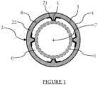
- the pipe 1 represents a section of a metal pipe 1, for example circular in shape, shown here in dotted lines.
- the pipe 1 ensures the circulation of a fluid which may be of various natures, for example a liquid or a gas.
- the pipe 1 may be part of a system for conditioning or cooling a fluid, or any other system capable of creating a condensation phenomenon at the level of the pipe 1.
- the fluid circulating in the pipe 1 may in particular be water or air.
- the pipe 1 may be installed within any container comprising a system within which a pipe ensures the circulation of a fluid colder than the external environment, for example a terrestrial construction such as a building or a vehicle such as a boat or an airplane.
- the pipe 1 is entirely covered by an insulating structure 2, of a shape substantially identical to the shape of the pipe 1, for example of a circular shape if the pipe 1 is also of a circular shape.
- the pipe 1 and the insulating structure 2 are centered around an axis of revolution 7.
- the insulating structure 2 is sectioned and has an opening 8, arranged radially along a radius of the axis of revolution 7 and longitudinally along the length of the insulating structure 2. The latter is wound around the pipe 1, then is fixed for example by an adhesive strip, not shown in the drawing. figure 1 .
- the insulating structure 2 comprises an inner wall 3 and an outer wall 4 which delimit the thickness of the insulating structure 2.
- the entire insulating structure 2 is composed of glass wool or rock wool, depending on the material chosen.
- the outer wall 4 can be covered with a thin layer of material ensuring the sealing of the insulating structure 2.
- the external wall 4 is thus advantageously covered with an aluminum sheet ensuring the sealing and/or protection of the insulating structure 2 against the external environment.
- the internal wall 3 of the insulating structure 2 is, in this exemplary embodiment, mainly circular, with the exception of protrusions 5, present in a regular and punctate manner in the internal volume delimited by the insulating structure 2.
- the protrusions 5 are formed during the manufacture of the insulating structure 2 and correspond to the counterforms of a mandrel comprising for example counterforms making it possible to obtain the insulating structure 2 as shown in the figure. figure 1
- the protrusions 5 are therefore an integral part of the internal wall 3 due to the shape of the mandrel with which the insulating structure 2 was extruded during the manufacturing process described above.
- the inner wall 3 at least partially delimits the protrusion 5.
- the other side of the protrusion 5 is delimited by a core 22 of the insulating structure 2.
- the inner wall 3 of the insulating structure forms a skin 21 which has been densified by heating during the manufacturing process of the insulating structure 2.
- This densified skin 21 may be located exclusively at the level of the protrusion 5, depending on the distribution of the heat exerted on the mandrel during the manufacturing of the insulating structure 2, as illustrated in FIG. figure 1 .
- this densified skin 21 can also extend over a plurality of outgrowths 5 and over the internal wall 3 located between two consecutive outgrowths 5.
- the outgrowths 5 are four in number, arranged at an angle of 90° to each other, thus forming a regular arrangement of the outgrowths 5 along the internal wall 3.
- the protrusions 5 have an ogive shape according to a section plane of the insulating structure perpendicular to the axis of revolution of this structure.
- each rounded apex of the protrusion 5 is in direct contact with the pipe 1.
- the protrusions 5 are of equal height relative to each other. In other words, the distance between the point of contact of the rounded apex of the protrusion 5 with the pipe 1 and a base of the protrusion 5 at the level of the internal wall 3 is identical regardless of the protrusion 5.
- the protrusions 5 thus allow the delimitation of an air space 6 between the pipe 1 and the internal wall 3, of a thickness equivalent to the height of the protrusions 5.
- the assembly formed by the core 22 and the protrusions 5 is made of glass wool or rock wool depending on the choice of the insulating material, just like the rest of the insulating structure 2.
- the insulating material of the insulating structure 2 at the protrusions 5, and advantageously between the protrusions is densified following the creation of the insulating structure 2 by pressing on the mandrel. This densification is due to a particular process of heating the mandrel to a temperature of around 350-400°C by means of a bundle of heating resistors or microwaves.
- the densified protrusions 5 are therefore denser than the external wall 4 of the insulating structure 2 and therefore ensure that the insulating structure 2 is maintained around the pipe 1 over the long term.
- FIG. 2 is a perspective representation of the insulating structure 2.
- several elements are represented in solid or dotted lines and correspond to different elements of the insulating structure 2.
- the thinnest dotted line corresponds to the axis of revolution 7.
- the insulating structure 2 shown in the figure 2 is circular in shape.
- the perspective representation therefore makes it possible to visualize the insulating structure 2 in the form of a right circular cylinder, centered around the axis of revolution 7.
- the two solid lines correspond to two diametrically opposite points on the external wall 4 of the insulating structure 2, delimiting the external dimensions of the insulating structure 2.
- the solid lines are parallel to each other, thus defining an insulating structure 2 of constant cylindrical shape in a longitudinal direction.
- the four strong dotted lines correspond to the protrusions 5.
- the growths 5 are four in number, arranged at an angle of 90° to each other.
- the perspective representation of the figure 2 illustrates the longitudinal extension of the outgrowths 5 over the entire length of the internal wall 3 of the insulating structure 2.
- the longitudinal extension of the outgrowths 5 is continuous, but it is quite possible to imagine a discontinuous longitudinal extension of the outgrowths 5, as long as the air space 6 is maintained over the entire pipe when the insulating structure 2 is put in place there.
- the protrusions 5 maintain their dimension in a constant manner.
- the air space 6 is present over the entire length of the pipe 1, which therefore guarantees protection against corrosion over the entire pipe 1, air circulation between the protrusions 5, and acoustic insulation of the pipe as described below.
- FIG 3 presents a method of manufacturing the insulating structure 2.
- This figure schematically shows a machine 30 capable of processing mineral fibers, for example glass wool or rock wool, so as to form products such as the insulating structure 2.
- the manufacturing method shown in the figure 3 allows the insulating structure 2 to be manufactured as shown in the previous figures.
- the machine 30 comprises a mandrel 31 and rollers 34.
- the mandrel 31 is capable of being driven in rotation in a direction 37, for example by means of a rotating shaft not shown in the figure.
- the machine 30 also comprises an arrival of a section 35 of mineral fibers along a direction 36, for example by means of a conveyor, not shown in the figure.
- the section 35 of mineral fibers is advantageously of small thickness in order to be able to obtain products that can vary in terms of thickness. Although this is not visible in the figure, it is obvious that the section 35 of mineral fibers and the mandrel 31 have a substantial longitudinal dimension, and this in order to create an insulating structure 2 of substantially cylindrical and of a longitudinal dimension suitable for being arranged around a pipe.
- the section 35 is wound around the mandrel 31 by rotating the latter in the direction 37.
- the mandrel 31 comprises counterforms 32, shown here in the form of recesses, corresponding to the protrusions of the insulating structure 2. These counterforms 32 can for example be machined directly in the mandrel 31.
- the counterforms 32 extend longitudinally along the mandrel 31.
- the rollers 34 have shapes that match the external wall of the insulating structure 2, and exert pressure on it, pressure allowing the counterforms 32 to be filled, but also to smooth the section 35 to avoid the appearance of manufacturing defects, for example folds.
- the rollers 34 are almost in contact with the mandrel 31. Subsequently, the more the section 35 is wound around the mandrel 31, the more the thickness of the insulating structure 2 increases, and therefore the more the rollers 34 move away from the mandrel 31 while maintaining a certain pressure ensuring their functions.
- the machine 30 can thus create an insulating structure 2 of a variable thickness depending on the insulation requirement, and corresponding to the number of windings of the section 35 around the mandrel 31.
- the mandrel 31 While being rotated, the mandrel 31 is heated to 350-400°C by means of, for example, electrical resistors 33 located within the structure of the mandrel 31, at the counterforms 32. It is these electrical resistors 33 which, by their heating function, ensure the densification of the internal wall of the insulating structure 2 at the level of the protrusions. Furthermore, it is the proximity between the electrical resistors 33 and the counterforms 32 which causes the densification of the internal wall of the insulating structure 2 which at least partially delimits the protrusions, thus forming the skin densified.
- the heating process by means of the resistors 33 is in no way limiting, the internal wall being able to be heated by microwaves directed towards the growths, for example.
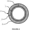
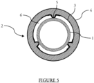
- THE figures 4 And 5 are schematic cross-sectional representations of two arrangements of the insulating structure 2 around the pipe 1 for the purpose of a sound insulation test. The same sound insulation test is carried out on four different models of the insulating structure 2, each according to the two arrangements shown in figure 4 And 5 .
- FIG 4 presents a first arrangement for the sound insulation test.
- the insulating structure 2 is wrapped around the pipe 1 so that the vast majority of the internal wall 3 of the insulating structure 2 is in direct contact with the pipe 1.
- the four models of the insulating structure 2 used for the sound insulation test therefore all have a dimension suitable for being wrapped around the pipe 1.
- the insulating structure 2 is then held around the pipe 1 for example by means of adhesive material.
- FIG. 5 has a second arrangement for the sound insulation test.
- This second arrangement corresponds to the insulating structure 2 according to the invention and therefore comprises several protrusions 5 at the level of the internal wall 3 of the insulating structure 2.
- the protrusions 5 are three in number, distributed equilaterally along the internal wall 3, and therefore ensure the formation of the air space 6.
- the insulating structure 2 is then held on the pipe 1 by adhesive material.
- the acoustic test is carried out with four models of insulating structure.
- Each of the four models has an internal diameter of 114mm.
- internal diameter it should be understood that this corresponds to the length between two points on the internal wall of the insulating structure diametrically opposite each other when the insulating structure is placed around the pipe.
- the four models have the same internal diameter since they are all placed around the same pipe to carry out the acoustic insulation test.
- a first model A has an insulating material thickness of 30mm and a linear weight of 1.0 kilograms per meter of length +/- 0.15 kilograms per meter of length.
- a second model B also has an insulating material thickness of 30mm and a linear weight of 1.2 kilograms per meter of length +/- 0.15 kilograms per meter of length.
- a third model C has an insulating material thickness of 60mm and a linear weight of 3.2 kilograms per meter of length +/- 0.2 kilograms per meter of length.
- a fourth model D has an insulating material thickness of 100mm and a linear weight of 4.4 kilograms per meter of length +/- 0.2 kilograms per meter of length.
- Each of the insulating structure models is wound in turn around the pipe, and this according to each of the two arrangements, a first time according to the first arrangement presented in figure 4 , and a second time according to the second arrangement presented in figure 5 .
- a white noise i.e. a noise with an identical sound level regardless of the frequency of said noise
- the test is repeated according to a given frequency range. From the sound level of the frequencies picked up by the microphone and depending on the initial sound level of the sound at the speaker output, an insertion loss in decibels is calculated. The higher the insertion loss, the more effective the insulating structure provides sound insulation.
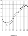
- the results of the sound insulation tests are presented on the Figures 6 to 9 .
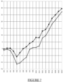
- Each of the Figures 6 to 9 shows a graph comprising two insertion loss curves as a function of sound frequency, one figure corresponding to a model of insulating structure.
- Each of the figures shows a curve with triangular marks corresponding to the curve of the results of the sound insulation test of the insulating structure arranged according to the first arrangement shown in figure 4 , and a curve with square marks corresponding to the curve of the results of the sound insulation test of the insulating structure arranged according to the second arrangement presented in figure 5
- the sound frequency range selected for the sound insulation test presents nineteen different sound frequencies varying between 100Hz and 6300Hz.
- FIG. 6 is a graph showing the results of the sound insulation test of the first model A according to the two arrangements presented above. Except for the three lowest frequencies where the insertion losses are identical or substantially identical, the insertion loss when the first model A of insulating structure is arranged according to the second arrangement is systematically higher than the insertion loss of the first model A is arranged according to the first arrangement, with an insertion loss differential of up to more than five decibels.
- FIG 7 is a graph from the sound insulation test identical to the previous figure, but carried out with the second model B of insulating structure.
- the insertion loss when the second model B is arranged according to the second arrangement is always higher than when the second model B is arranged according to the first arrangement, with an insertion loss differential of up to approximately eight decibels.
- FIG 8 is a graph showing the results of the sound insulation test with the third model C of insulating structure. Except for the measurement at 160Hz which may seem negligible compared to the whole curve, the insertion loss of the third model C arranged according to the second arrangement is always higher. Just like for the second model B of insulating structure, an insertion loss differential for the third model C can also extend up to about eight decibels.
- FIG. 9 is a graph showing the results of the sound insulation test with the fourth D-model of insulating structure.
- the results of the fourth D-model show less biased measurements than for the previous insulating structure models, particularly for very low frequencies and very high frequencies.
- the overall result nevertheless remains in favor of the second arrangement where the insertion loss remains the highest for most sound frequencies, with an insertion loss differential of up to seven decibels.
- the insertion loss is higher when the insulating structures are arranged according to the second arrangement, i.e. with the presence of protrusions on the internal wall of the insulating structure ensuring the creation of an air space between the pipe and the insulating structure, despite the differences in characteristics between the four models of insulating structure, whether the thickness of the insulating material or the linear weight thereof.
- the presence of such an air space therefore reinforces the acoustic insulation of the pipe, in a manner at least partially independent of the properties of the insulating structure.
- the embodiment of the second arrangement differs from the embodiment of the invention presented through the detailed description, the insulating structure according to the invention also makes it possible to form an air space between the pipe and the insulating structure by means of the protrusions.
- the invention therefore has an acoustic insulation function in addition to solving the technical problem linked to corrosion of the pipe following condensation thereof.
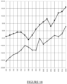
- FIG 10 is a graph showing the results of the sound insulation test as previously performed.
- the mineral wool used for the test corresponds to a fifth model E, with an insulating material thickness of 30mm, like the first model A and the second model B.
- the fifth model E has a density of 66kg/m 3 .
- the fifth model E is virtually wrapped around a pipe, and is virtually traversed by several white noises at different frequencies.
- the two arrangements of the fifth model E are similar to the arrangements presented in figure 4 And 5 .
- the acoustic test carried out here is identical to that mentioned when describing the Figures 6 to 9 .
- the frequency range used is between 100 Hz and 4000 Hz and is applied on the fifth model E according to the first arrangement and according to the second arrangement.
- the insertion loss in decibels is measured for each frequency and the results are presented in figure 10 . It can be seen that the insertion loss differential is in favor of the second arrangement, with a differential ranging from 5 decibels to 15 decibels.
- the acoustic test is therefore also conclusive.
- the invention is not limited to this embodiment. It is obviously possible to choose the insulating material according to the needs. It is also possible to vary the height of the protrusions 5 according to the diameter of the insulating structure 2, or quite simply in order to create a larger air space 6, if this is necessary.
- the number and the shape seen in section of the protrusions 5 can also vary, and this according to the shape of the mandrel on which the insulating structure 2 is formed.
- the increase in the number of protrusions 5 ensures better stability of the insulating structure 2 around the pipe 1 but reduces the overall volume of the air space 6.
Landscapes
- Engineering & Computer Science (AREA)
- General Engineering & Computer Science (AREA)
- Mechanical Engineering (AREA)
- Textile Engineering (AREA)
- Thermal Insulation (AREA)
Claims (10)
- Eine zylindrische thermisch und akustisch isolierende Struktur (2), die so konfiguriert ist, dass sie ein Rohr (1) zum Transport eines Fluids abdeckt, das auf variable Temperaturen gebracht werden kann, einschließlich einer Innenwand (3) und einer Außenwand (4), wobei die Isolierstruktur (2) mit mindestens einem Vorsprung (5), der aus seiner Innenwand (3) hervorsteht, um so einen Luftraum (6) zwischen der Innenwand (3) und dem Rohr (1) zu erzeugen, wobei die Innenwand (3) von die isolierende Struktur (2), die den Vorsprung (5) zumindest teilweise begrenzt, dichter ist als die Außenwand (4) der isolierenden Struktur (2), dadurch gekennzeichnet, dass eine Verdichtung des Vorsprungs (5) ausgehend von der Innenwand ( 3) Versehen des Vorsprungs (5) mit einem erhöhten Widerstand gegen Verformung und Ermöglichen der Erhaltung des Luftraums (6) zwischen dem Rohr (1) und der Isolierstruktur (2).
- Isolierstruktur (2) nach Anspruch 1, umfassend mindestens zwei Vorsprünge (5).
- Isolierstruktur (2) nach einem der vorhergehenden Ansprüche, bei der eine am Vorsprung (5) gemessene Dicke der Innenwand zwischen 0,1 mm und 5 mm beträgt.
- Isolierstruktur (2) nach einem der vorhergehenden Ansprüche, bei der die Dichte der Außenwand (4) der Isolierstruktur (2) einen relativen Wert zwischen 40 % und 70 % des Wertes aufweist Dichte der Innenwand (3) der Isolierstruktur (2) am Vorsprung (5).
- Isolierstruktur (2) nach einem der vorhergehenden Ansprüche, bei der das Isoliermaterial, aus dem sie besteht, Mineralwolle ist.
- Isolierstruktur (2) nach einem der vorhergehenden Ansprüche, bei der der aus der Innenwand (3) hervortretende Vorsprung (5) in Richtung der Rotationsachse (7) des durch sie gebildeten Zylinders gekrümmt ist die isolierende Struktur (2).
- Isolierstruktur (2) nach einem der vorhergehenden Ansprüche, umfassend eine Vielzahl von Vorsprüngen (5), die aus der Innenwand (3) herausragen, wobei die Vorsprünge (5) regelmäßig winkelmäßig verteilt sind.
- Die isolierende Struktur (2) nach einem der vorstehenden Ansprüche, bei der die Außenwand (4) mit einer Schicht aus leckagefreiem Material bedeckt ist.
- Isolierstruktur (2) nach dem vorhergehenden Anspruch, bei der die Schicht aus leckagefreiem Material der Außenwand (4) eine Metallfolie ist.
- Verfahren zur Herstellung einer thermisch und akustisch isolierenden Struktur (2) nach einem der vorhergehenden Ansprüche, einschließlich:- einen Schritt des Wickelns eines Abschnitts (35) aus Isoliermaterial um einen Dorn (31) mit Gegenformen (32),- einen Schritt des Erhitzens des Materials mittels des Dorns (32),- einen Schritt des Pressens des Abschnitts (35) aus Isoliermaterial auf den Dorn (31) mittels Rollen (34).
Applications Claiming Priority (2)
| Application Number | Priority Date | Filing Date | Title |
|---|---|---|---|
| FR1908483A FR3099225B1 (fr) | 2019-07-25 | 2019-07-25 | Structure isolante pour conduite de fluide |
| PCT/FR2020/051300 WO2021014084A1 (fr) | 2019-07-25 | 2020-07-17 | Structure isolante pour conduite de fluide |
Publications (3)
| Publication Number | Publication Date |
|---|---|
| EP4004424A1 EP4004424A1 (de) | 2022-06-01 |
| EP4004424B1 true EP4004424B1 (de) | 2025-02-19 |
| EP4004424C0 EP4004424C0 (de) | 2025-02-19 |
Family
ID=68806980
Family Applications (1)
| Application Number | Title | Priority Date | Filing Date |
|---|---|---|---|
| EP20753996.6A Active EP4004424B1 (de) | 2019-07-25 | 2020-07-17 | Isolierstruktur für ein flüssigkeitsrohr |
Country Status (6)
| Country | Link |
|---|---|
| EP (1) | EP4004424B1 (de) |
| JP (1) | JP2022542358A (de) |
| ES (1) | ES3018334T3 (de) |
| FR (1) | FR3099225B1 (de) |
| PL (1) | PL4004424T3 (de) |
| WO (1) | WO2021014084A1 (de) |
Families Citing this family (4)
| Publication number | Priority date | Publication date | Assignee | Title |
|---|---|---|---|---|
| JP7157280B1 (ja) * | 2021-06-25 | 2022-10-19 | 日鉄マイクロメタル株式会社 | 半導体装置用ボンディングワイヤ |
| CN114001236A (zh) * | 2021-10-22 | 2022-02-01 | 河北乾海管道制造有限公司 | 一种预制直埋保温管 |
| US12358627B2 (en) | 2022-10-21 | 2025-07-15 | The Boeing Company | Acoustic air duct for environmental control system in vehicle |
| IT202400004162A1 (it) * | 2024-02-27 | 2025-08-27 | Isolmec S R L | Involucro termoisolante, particolarmente per fumisteria |
Family Cites Families (8)
| Publication number | Priority date | Publication date | Assignee | Title |
|---|---|---|---|---|
| DE1875813U (de) * | 1960-05-13 | 1963-07-18 | Basf Ag | Wickelband fuer waerme-isolierungen von rohren, behaeltern od. dgl. |
| JPS4824216Y1 (de) * | 1968-02-07 | 1973-07-13 | ||
| JPS6124795Y2 (de) * | 1980-03-11 | 1986-07-25 | ||
| JPS60129596U (ja) * | 1984-02-09 | 1985-08-30 | 古河電気工業株式会社 | 断熱管 |
| JPH04248098A (ja) * | 1991-01-24 | 1992-09-03 | Furukawa Electric Co Ltd:The | 難燃性断熱管 |
| JPH07190747A (ja) * | 1993-12-27 | 1995-07-28 | Mitsui Toatsu Chem Inc | 合成樹脂シートの歪測定方法 |
| EP0828965B1 (de) * | 1995-05-22 | 2001-03-21 | Rockwool International A/S | Verfahren zur isolierung eines rohres mit einer rohrförmigen umhüllung |
| JP5351727B2 (ja) * | 2009-04-24 | 2013-11-27 | 積水化学工業株式会社 | 耐火遮音管 |
-
2019
- 2019-07-25 FR FR1908483A patent/FR3099225B1/fr active Active
-
2020
- 2020-07-17 JP JP2022504228A patent/JP2022542358A/ja active Pending
- 2020-07-17 WO PCT/FR2020/051300 patent/WO2021014084A1/fr not_active Ceased
- 2020-07-17 PL PL20753996.6T patent/PL4004424T3/pl unknown
- 2020-07-17 EP EP20753996.6A patent/EP4004424B1/de active Active
- 2020-07-17 ES ES20753996T patent/ES3018334T3/es active Active
Also Published As
| Publication number | Publication date |
|---|---|
| FR3099225B1 (fr) | 2021-12-24 |
| FR3099225A1 (fr) | 2021-01-29 |
| WO2021014084A1 (fr) | 2021-01-28 |
| EP4004424A1 (de) | 2022-06-01 |
| ES3018334T3 (es) | 2025-05-16 |
| PL4004424T3 (pl) | 2025-04-14 |
| JP2022542358A (ja) | 2022-10-03 |
| EP4004424C0 (de) | 2025-02-19 |
Similar Documents
| Publication | Publication Date | Title |
|---|---|---|
| EP4004424B1 (de) | Isolierstruktur für ein flüssigkeitsrohr | |
| EP0890056B1 (de) | Leitungsrohr des typs doppelwärmedämpfungsmantel | |
| CA2935773C (fr) | Protection contre le feu d'un carter de soufflante en materiau composite | |
| FR2468063A1 (fr) | Conduit calorifuge pour le transport de fluides | |
| EP1232361B1 (de) | Komplexe rohrförmige isolierung für leitungen | |
| EP0922177A1 (de) | Verfahren zur herstellung einer biegsamen leitung | |
| FR2975164A1 (fr) | Dispositif et procede d'isolation thermique d'une zone de raccordement d'embouts de connexion de deux conduites sous-marines calorifugees. | |
| EP1744875B1 (de) | Thermisches isolationsmaterial | |
| CA2478788A1 (fr) | Dispositif abradable sur carter de soufflante d'un moteur de turbine a gaz | |
| EP4214044A1 (de) | Form zur herstellung eines turbomaschinengebläsegehäuses aus einem verbundstoff mit unterschiedlicher expansion | |
| WO1998034061A1 (fr) | Enveloppe d'isolation thermique, notamment pour la construction de canalisations sous-marines vehiculant des produits petroliers | |
| EP3953569A1 (de) | Verfahren zum erfassen einer rauheit in einer abreibbaren schicht in einem bläsergehäuse | |
| FR2578026A1 (fr) | Procede pour la fabrication d'une conduite tubulaire isolee thermiquement | |
| FR2777628A1 (fr) | Procede de realisation d'une conduite calorifugee a enveloppe externe de protection et conduite ainsi realisee | |
| FR3002376A1 (fr) | Bouchon d'etancheite pour cable electrique contre les infiltrations d'air dans les batiments et procede de pose du cable electrique | |
| FR2664850A1 (fr) | Procede de gainage d'un faisceau d'elements filiformes, dispositif pour le mettre en óoeuvre et faisceau obtenu. | |
| EP1495214A1 (de) | Abgasraum mit einer umhüllung zur begrenzung des abgasstromes | |
| FR2927952A1 (fr) | Paroi insonorisante, en particulier pour nacelle de turboreacteur | |
| WO2024061800A1 (fr) | Réservoir de gaz sous pression pour véhicule | |
| FR3146160A1 (fr) | Carter annulaire de turbomachine et son procédé de fabrication. | |
| FR2504520A1 (fr) | Materiau formable d'isolation et d'absorption acoustiques et son procede de formage | |
| FR2936090A1 (fr) | Gaine tubulaire annelee a enveloppe | |
| EP3636909B1 (de) | Akustisch dämpfend vorrichtung für eine aufgeladenen brennkraftmaschine | |
| FR2477670A1 (fr) | Revetement pour l'isolation thermique d'une paroi | |
| EP4551953A1 (de) | Vorrichtung zur akustischen erfassung eines lichtbogens |
Legal Events
| Date | Code | Title | Description |
|---|---|---|---|
| STAA | Information on the status of an ep patent application or granted ep patent |
Free format text: STATUS: UNKNOWN |
|
| STAA | Information on the status of an ep patent application or granted ep patent |
Free format text: STATUS: THE INTERNATIONAL PUBLICATION HAS BEEN MADE |
|
| PUAI | Public reference made under article 153(3) epc to a published international application that has entered the european phase |
Free format text: ORIGINAL CODE: 0009012 |
|
| STAA | Information on the status of an ep patent application or granted ep patent |
Free format text: STATUS: REQUEST FOR EXAMINATION WAS MADE |
|
| 17P | Request for examination filed |
Effective date: 20220217 |
|
| AK | Designated contracting states |
Kind code of ref document: A1 Designated state(s): AL AT BE BG CH CY CZ DE DK EE ES FI FR GB GR HR HU IE IS IT LI LT LU LV MC MK MT NL NO PL PT RO RS SE SI SK SM TR |
|
| DAV | Request for validation of the european patent (deleted) | ||
| DAX | Request for extension of the european patent (deleted) | ||
| STAA | Information on the status of an ep patent application or granted ep patent |
Free format text: STATUS: EXAMINATION IS IN PROGRESS |
|
| 17Q | First examination report despatched |
Effective date: 20231108 |
|
| GRAP | Despatch of communication of intention to grant a patent |
Free format text: ORIGINAL CODE: EPIDOSNIGR1 |
|
| STAA | Information on the status of an ep patent application or granted ep patent |
Free format text: STATUS: GRANT OF PATENT IS INTENDED |
|
| INTG | Intention to grant announced |
Effective date: 20241008 |
|
| GRAS | Grant fee paid |
Free format text: ORIGINAL CODE: EPIDOSNIGR3 |
|
| GRAA | (expected) grant |
Free format text: ORIGINAL CODE: 0009210 |
|
| STAA | Information on the status of an ep patent application or granted ep patent |
Free format text: STATUS: THE PATENT HAS BEEN GRANTED |
|
| AK | Designated contracting states |
Kind code of ref document: B1 Designated state(s): AL AT BE BG CH CY CZ DE DK EE ES FI FR GB GR HR HU IE IS IT LI LT LU LV MC MK MT NL NO PL PT RO RS SE SI SK SM TR |
|
| REG | Reference to a national code |
Ref country code: GB Ref legal event code: FG4D Free format text: NOT ENGLISH |
|
| REG | Reference to a national code |
Ref country code: CH Ref legal event code: EP |
|
| REG | Reference to a national code |
Ref country code: DE Ref legal event code: R096 Ref document number: 602020046327 Country of ref document: DE |
|
| REG | Reference to a national code |
Ref country code: IE Ref legal event code: FG4D Free format text: LANGUAGE OF EP DOCUMENT: FRENCH |
|
| U01 | Request for unitary effect filed |
Effective date: 20250304 |
|
| U07 | Unitary effect registered |
Designated state(s): AT BE BG DE DK EE FI FR IT LT LU LV MT NL PT RO SE SI Effective date: 20250312 |
|
| REG | Reference to a national code |
Ref country code: ES Ref legal event code: FG2A Ref document number: 3018334 Country of ref document: ES Kind code of ref document: T3 Effective date: 20250516 |
|
| PG25 | Lapsed in a contracting state [announced via postgrant information from national office to epo] |
Ref country code: RS Free format text: LAPSE BECAUSE OF FAILURE TO SUBMIT A TRANSLATION OF THE DESCRIPTION OR TO PAY THE FEE WITHIN THE PRESCRIBED TIME-LIMIT Effective date: 20250519 |
|
| PGFP | Annual fee paid to national office [announced via postgrant information from national office to epo] |
Ref country code: PL Payment date: 20250608 Year of fee payment: 6 |
|
| PGFP | Annual fee paid to national office [announced via postgrant information from national office to epo] |
Ref country code: GB Payment date: 20250529 Year of fee payment: 6 |
|
| PG25 | Lapsed in a contracting state [announced via postgrant information from national office to epo] |
Ref country code: IS Free format text: LAPSE BECAUSE OF FAILURE TO SUBMIT A TRANSLATION OF THE DESCRIPTION OR TO PAY THE FEE WITHIN THE PRESCRIBED TIME-LIMIT Effective date: 20250619 |
|
| PG25 | Lapsed in a contracting state [announced via postgrant information from national office to epo] |
Ref country code: HR Free format text: LAPSE BECAUSE OF FAILURE TO SUBMIT A TRANSLATION OF THE DESCRIPTION OR TO PAY THE FEE WITHIN THE PRESCRIBED TIME-LIMIT Effective date: 20250219 |
|
| U20 | Renewal fee for the european patent with unitary effect paid |
Year of fee payment: 6 Effective date: 20250606 |
|
| PG25 | Lapsed in a contracting state [announced via postgrant information from national office to epo] |
Ref country code: GR Free format text: LAPSE BECAUSE OF FAILURE TO SUBMIT A TRANSLATION OF THE DESCRIPTION OR TO PAY THE FEE WITHIN THE PRESCRIBED TIME-LIMIT Effective date: 20250520 |
|
| PG25 | Lapsed in a contracting state [announced via postgrant information from national office to epo] |
Ref country code: SM Free format text: LAPSE BECAUSE OF FAILURE TO SUBMIT A TRANSLATION OF THE DESCRIPTION OR TO PAY THE FEE WITHIN THE PRESCRIBED TIME-LIMIT Effective date: 20250219 |
|
| PGFP | Annual fee paid to national office [announced via postgrant information from national office to epo] |
Ref country code: ES Payment date: 20250805 Year of fee payment: 6 |
|
| PGFP | Annual fee paid to national office [announced via postgrant information from national office to epo] |
Ref country code: NO Payment date: 20250709 Year of fee payment: 6 |
|
| PGFP | Annual fee paid to national office [announced via postgrant information from national office to epo] |
Ref country code: TR Payment date: 20250707 Year of fee payment: 6 |
|
| PGFP | Annual fee paid to national office [announced via postgrant information from national office to epo] |
Ref country code: CZ Payment date: 20250701 Year of fee payment: 6 |
|
| PG25 | Lapsed in a contracting state [announced via postgrant information from national office to epo] |
Ref country code: SK Free format text: LAPSE BECAUSE OF FAILURE TO SUBMIT A TRANSLATION OF THE DESCRIPTION OR TO PAY THE FEE WITHIN THE PRESCRIBED TIME-LIMIT Effective date: 20250219 |
|
| PLBE | No opposition filed within time limit |
Free format text: ORIGINAL CODE: 0009261 |
|
| STAA | Information on the status of an ep patent application or granted ep patent |
Free format text: STATUS: NO OPPOSITION FILED WITHIN TIME LIMIT |
|
| REG | Reference to a national code |
Ref country code: CH Ref legal event code: L10 Free format text: ST27 STATUS EVENT CODE: U-0-0-L10-L00 (AS PROVIDED BY THE NATIONAL OFFICE) Effective date: 20251231 |
|
| 26N | No opposition filed |
Effective date: 20251120 |
|
| REG | Reference to a national code |
Ref country code: CH Ref legal event code: H13 Free format text: ST27 STATUS EVENT CODE: U-0-0-H10-H13 (AS PROVIDED BY THE NATIONAL OFFICE) Effective date: 20260224 |
|
| PG25 | Lapsed in a contracting state [announced via postgrant information from national office to epo] |
Ref country code: CH Free format text: LAPSE BECAUSE OF NON-PAYMENT OF DUE FEES Effective date: 20250731 |