EP4004446B1 - Procédé et système d'équilibrage d'un réseau hydronique - Google Patents
Procédé et système d'équilibrage d'un réseau hydronique Download PDFInfo
- Publication number
- EP4004446B1 EP4004446B1 EP20729670.8A EP20729670A EP4004446B1 EP 4004446 B1 EP4004446 B1 EP 4004446B1 EP 20729670 A EP20729670 A EP 20729670A EP 4004446 B1 EP4004446 B1 EP 4004446B1
- Authority
- EP
- European Patent Office
- Prior art keywords
- valve
- regulating valves
- regulating
- flow
- fluid
- Prior art date
- Legal status (The legal status is an assumption and is not a legal conclusion. Google has not performed a legal analysis and makes no representation as to the accuracy of the status listed.)
- Active
Links
Images



Classifications
-
- F—MECHANICAL ENGINEERING; LIGHTING; HEATING; WEAPONS; BLASTING
- F24—HEATING; RANGES; VENTILATING
- F24F—AIR-CONDITIONING; AIR-HUMIDIFICATION; VENTILATION; USE OF AIR CURRENTS FOR SCREENING
- F24F11/00—Control or safety arrangements
- F24F11/70—Control systems characterised by their outputs; Constructional details thereof
- F24F11/80—Control systems characterised by their outputs; Constructional details thereof for controlling the temperature of the supplied air
- F24F11/83—Control systems characterised by their outputs; Constructional details thereof for controlling the temperature of the supplied air by controlling the supply of heat-exchange fluids to heat-exchangers
- F24F11/84—Control systems characterised by their outputs; Constructional details thereof for controlling the temperature of the supplied air by controlling the supply of heat-exchange fluids to heat-exchangers using valves
-
- F—MECHANICAL ENGINEERING; LIGHTING; HEATING; WEAPONS; BLASTING
- F25—REFRIGERATION OR COOLING; COMBINED HEATING AND REFRIGERATION SYSTEMS; HEAT PUMP SYSTEMS; MANUFACTURE OR STORAGE OF ICE; LIQUEFACTION SOLIDIFICATION OF GASES
- F25D—REFRIGERATORS; COLD ROOMS; ICE-BOXES; COOLING OR FREEZING APPARATUS NOT OTHERWISE PROVIDED FOR
- F25D17/00—Arrangements for circulating cooling fluids; Arrangements for circulating gas, e.g. air, within refrigerated spaces
- F25D17/02—Arrangements for circulating cooling fluids; Arrangements for circulating gas, e.g. air, within refrigerated spaces for circulating liquids, e.g. brine
-
- F—MECHANICAL ENGINEERING; LIGHTING; HEATING; WEAPONS; BLASTING
- F25—REFRIGERATION OR COOLING; COMBINED HEATING AND REFRIGERATION SYSTEMS; HEAT PUMP SYSTEMS; MANUFACTURE OR STORAGE OF ICE; LIQUEFACTION SOLIDIFICATION OF GASES
- F25D—REFRIGERATORS; COLD ROOMS; ICE-BOXES; COOLING OR FREEZING APPARATUS NOT OTHERWISE PROVIDED FOR
- F25D29/00—Arrangement or mounting of control or safety devices
- F25D29/005—Mounting of control devices
-
- G—PHYSICS
- G05—CONTROLLING; REGULATING
- G05B—CONTROL OR REGULATING SYSTEMS IN GENERAL; FUNCTIONAL ELEMENTS OF SUCH SYSTEMS; MONITORING OR TESTING ARRANGEMENTS FOR SUCH SYSTEMS OR ELEMENTS
- G05B15/00—Systems controlled by a computer
- G05B15/02—Systems controlled by a computer electric
-
- F—MECHANICAL ENGINEERING; LIGHTING; HEATING; WEAPONS; BLASTING
- F24—HEATING; RANGES; VENTILATING
- F24D—DOMESTIC- OR SPACE-HEATING SYSTEMS, e.g. CENTRAL HEATING SYSTEMS; DOMESTIC HOT-WATER SUPPLY SYSTEMS; ELEMENTS OR COMPONENTS THEREFOR
- F24D2220/00—Components of central heating installations excluding heat sources
- F24D2220/02—Fluid distribution means
- F24D2220/0264—Hydraulic balancing valves
-
- F—MECHANICAL ENGINEERING; LIGHTING; HEATING; WEAPONS; BLASTING
- F24—HEATING; RANGES; VENTILATING
- F24D—DOMESTIC- OR SPACE-HEATING SYSTEMS, e.g. CENTRAL HEATING SYSTEMS; DOMESTIC HOT-WATER SUPPLY SYSTEMS; ELEMENTS OR COMPONENTS THEREFOR
- F24D2220/00—Components of central heating installations excluding heat sources
- F24D2220/02—Fluid distribution means
- F24D2220/0292—Fluid distribution networks
-
- F—MECHANICAL ENGINEERING; LIGHTING; HEATING; WEAPONS; BLASTING
- F24—HEATING; RANGES; VENTILATING
- F24D—DOMESTIC- OR SPACE-HEATING SYSTEMS, e.g. CENTRAL HEATING SYSTEMS; DOMESTIC HOT-WATER SUPPLY SYSTEMS; ELEMENTS OR COMPONENTS THEREFOR
- F24D2220/00—Components of central heating installations excluding heat sources
- F24D2220/04—Sensors
-
- F—MECHANICAL ENGINEERING; LIGHTING; HEATING; WEAPONS; BLASTING
- F24—HEATING; RANGES; VENTILATING
- F24D—DOMESTIC- OR SPACE-HEATING SYSTEMS, e.g. CENTRAL HEATING SYSTEMS; DOMESTIC HOT-WATER SUPPLY SYSTEMS; ELEMENTS OR COMPONENTS THEREFOR
- F24D2220/00—Components of central heating installations excluding heat sources
- F24D2220/04—Sensors
- F24D2220/044—Flow sensors
Definitions
- the present invention relates to a method and a computer system for balancing a hydronic network. Specifically, the present invention relates to a method and a computer system for balancing a hydronic network that comprises a plurality of parallel zones with a regulating valve in each zone for regulating a flow of fluid through the respective zone.
- Hydronic networks typically comprise multiple consumers, e.g. thermal energy exchangers, arranged in parallel zones, meaning parallel branches or lines, through which a liquid fluid is transported for distributing thermal energy for the purpose of heating or cooling.
- the zones and consumers typically have different designs and configurations, meaning that they have different diameters and/or lengths of the transport lines - for example, pipe conduits - and have different and/or varying flow volumes and/or throughput.
- the consumers or zones are each configured with a compensation- or balancing organ, for example a regulating valve with a motorized actuator, which sets the flow through the respective consumer at different degrees of opening and/or valve positions.
- a balancing method for a network for the distribution of a non-compressed liquid is described in DE 69706458 , wherein for each branch, two pressure connection points are arranged on both sides of the compensating organ, and a further third pressure connection point is arranged at a distance therefrom.
- flow measurements are carried out by measuring the difference in flow on both sides of the respective compensating organ, and a measurement of a pressure difference is carried out by means of the third pressure connection point.
- the hydraulic flow capacity coefficients of all branches and segments on the primary line are calculated.
- the adjustment positions of each compensating organ are calculated and set on the basis of knowledge of the desired flow in each branch and utilizing the specific flow capacity coefficients.
- the compensation method requires multiple pressure connection points for each compensating organ, and is not designed for a dynamic balancing of a fluid transport system.
- EP 2 085 707 shows the hydraulic balancing of a heating system, wherein a heating element is equipped with a measuring device for measurement of the pressure and flow volume. Means are included for the detection of the flow volume as provided, as are means for detecting the pressure difference between the in-flow and the outlet flow. Means for the detection of the flow volume are arranged on the heating element, and serve the purpose of eliminating errors and automating the balancing.
- EP 0 795 724 which is in the same patent family as DE 69706458 , shows substantially the same features as DE 69706458 .
- DE 199 12 588 shows a hydraulic system having multiple conduit lines.
- valves with an electronic flow volume measuring device and an actuator drive are arranged in both a primary circuit and in the conduit lines of the consumer circuits.
- EP 2 157 376 shows an arrangement for hydraulically balancing a system for the purpose of cooling or heating.
- the system has an in-flow line, an outlet flow line, a throttle device, and a measuring device for a flow volume. Valves are included in each line for the purpose of hydraulic balancing, and measuring means are included for the purpose of determining the flows into the individual lines.
- US8024161 describes a method and system for optimal model-based multivariable balancing for distributed hydraulic networks based on global differential pressure/flow rate information.
- US8024161 uses a simplified mathematical model of a hydraulic network and a set of measured flow values in all the zones of the hydraulic network to identify unknown network parameters.
- valve settings are balanced by calculating the sum of pressure drops across the balancing valves and by solving an optimization problem to minimize the sum of pressure drops across the balancing valves in a non-iterative approach.
- WO 2014/094991 in the name of the applicant, describes a method for balancing a hydronic network that comprises a plurality of consumers arranged in parallel zones with regulating valves in each zone for regulating the flow of fluid through the respective zone.
- One common (shared) flow sensor is used to measure the total flow of fluid through the plurality of parallel zones.
- individual flow characteristics are recorded which indicate for a respective regulating valve the total flow of fluid measured by the common flow sensor at different valve positions of the respective regulating valve, while the remaining other regulating valves of the hydronic network are set to a closed valve position.
- a balancing factor is calculated based on the measured current total flow and the sum of the desired target flows through the consumers.
- Dynamic balancing of the hydronic network or its consumers, respectively, is implemented by setting the valve position of the regulating valves based on the characteristic data and the target flows scaled using the balancing factor.
- the balancing method disclosed in WO 2014/094991 performs well in configurations where the settings of the regulating valves in the parallel zones do not significantly influence each other.
- WO 2014/094991 discloses the features of the preamble of independent claims 1, 11 and 21.
- a multi-zone hydronic network comprises a plurality of parallel zones with a regulating valve in each zone for regulating a flow of fluid through the respective zone.
- the above-mentioned objects are particularly achieved in that for balancing the hydronic network, one flow sensor is used to measure a total flow of fluid through the plurality of parallel zones of the hydronic network.
- individual flow characteristics are recorded in a computer. The individual flow characteristics indicate for a respective regulating valve the total flow of fluid measured by the flow sensor at different valve positions of the respective regulating valve, while the remaining other regulating valves of the hydronic network are set to a closed valve position. Further, for each of the regulating valves, combined flow characteristics are recorded in the computer.
- the combined flow characteristics indicate for the respective regulating valve the total flow of fluid measured by the flow sensor at different valve positions of the respective regulating valve, while the remaining other regulating valves of the hydronic network are set to an open valve position.
- the computer determines correction factors for each of the regulating valves, using the individual flow characteristics of the respective regulating valve and the combined flow characteristics of the respective regulating valve,
- the computer balances the hydronic network by setting the valve positions of the regulating valves using target flows for the zones and the correction factors of the regulating valves.
- the computer balances the hydronic network by determining individual valve positions for the regulating valves, using the target flows for the zones and the individual flow characteristics of the regulating valves, and determining the correction factors for each of the regulating valves further using the individual valve positions of the regulating valves.
- the computer balances the hydronic network by performing an iteration process which includes determining in a first step correction factors for the regulating valves, using individual valve positions for the regulating valves, determining in a second step corrected valve positions for the regulating valves, using the target flows for the zones and the correction factors of the regulating valves, and repeating the first step and the second step, using the corrected valve positions from the second step as the individual valve positions in the first step.
- the computer uses the corrected valve positions for determining whether an iteration end point is reached, prior to the repeating of the first step and the second step.
- the computer records the combined flow characteristics by recording for each of the regulating valves the total flow of fluid measured by the flow sensor at different valve positions of the respective regulating valve and at various valve positions of the remaining other regulating valves of the hydronic network, in a range from closed valve position to fully open valve position; and the computer determines the correction factors for each of the regulating valves for a plurality of different valve positions of the regulating valves of the hydronic network.
- the computer records for each of the regulating valves a complementary flow of fluid.
- the complementary flow of fluid indicates for the respective regulating valve the total flow of fluid measured by the flow sensor at a closed valve position of the respective regulating valve, while the remaining other regulating valves of the hydronic network are set to the open valve position.
- the computer determines the correction factors using the complementary flow of fluid of the respective regulating valve and the combined flow characteristics of the respective regulating valve.
- the computer computes dependent flow characteristics for each of the regulating valves, using the combined flow characteristics of the respective regulating valve and the total flow of fluid measured by the flow sensor at a closed valve position of the respective regulating valve, while the remaining other regulating valves of the hydronic network are set to the open valve positions; and the computer determines the correction factors for each of the regulating valves by applying an objective function to the dependent flow characteristics of the respective regulating valve and the individual flow characteristics of the respective regulating valve.
- the computer determines the correction factors by calculating a mean valve position from the valve positions of the regulating valves, and determining the correction factor for the respective regulating valve of a particular zone using the mean valve position and a zone-specific dependency factor of the particular zone.
- a pressure sensor is used to measure a current system pressure of the hydronic network, and the computer scales the total flow of fluid measured by the flow sensor, using the current system pressure.
- one or more individual flow sensors are used to measure individual flows of fluid through respective regulating valves, and the computer uses the individual flows of fluid measured by the individual flow sensors for determining the individual flow characteristics of the respective regulating valves and the combined flow characteristics of the respective regulating valves.
- the present invention also relates to a computer system for implementing and executing the method; specifically, a computer system for balancing the hydronic network, the computer system comprising a processor configured to: receive from a flow sensor of the hydronic network the total flow of fluid through the plurality of parallel zones; record for each of the regulating valves individual flow characteristics, the individual flow characteristics indicating for a respective regulating valve the total flow of fluid measured by the flow sensor at different valve positions of the respective regulating valve, while the remaining other regulating valves of the hydronic network are set to a closed valve position; record for each of the regulating valves combined flow characteristics, the combined flow characteristics indicating for the respective regulating valve the total flow of fluid measured by the flow sensor at different valve positions of the respective regulating valve, while the remaining other regulating valves of the hydronic network are set to an open valve position; determine correction factors for each of the regulating valves, using the individual flow characteristics of the respective regulating valve and the combined flow characteristics of the respective regulating valve
- the computer system or its processor is configured to balance the hydronic network by determining individual valve positions for the regulating valves using the target flows for the zones and the individual flow characteristics of the regulating valves, and determining the correction factors for each of the regulating valves further using the individual valve positions of the regulating valves.
- the computer system or its processor, respectively is configured to balance the hydronic network by performing an iteration process which includes determining in a first step correction factors for the regulating valves using individual valve positions for the regulating valves, determining in a second step corrected valve positions for the regulating valves, using the target flows for the zones and the correction factors of the regulating valves, and repeating the first step and the second step, using the corrected valve positions from the second step as the individual valve positions in the first step.
- the computer system or its processor, respectively is configured to use the corrected valve positions for determining whether an iteration end point is reached, prior to the repeating of the first step and the second step.
- the computer system or its processor is configured to record the combined flow characteristics by recording for each of the regulating valves the total flow of fluid measured by the flow sensor at different valve positions of the respective regulating valve and at various valve positions of the remaining other regulating valves of the hydronic network, in a range from closed valve position to fully open valve position; and determine the correction factors for each of the regulating valves for a plurality of different valve positions of the regulating valves of the hydronic network.
- the computer system or its processor, respectively is configured to record for each of the regulating valves a complementary flow of fluid.
- the complementary flow of fluid indicates for the respective regulating valve the total flow of fluid measured by the flow sensor at a closed valve position of the respective regulating valve, while the remaining other regulating valves of the hydronic network are set to the open valve position.
- the computer is further configured to determine the correction factors using the complementary flow of fluid of the respective regulating valve and the combined flow characteristics of the respective regulating valve.
- the computer system or its processor is configured to compute dependent flow characteristics for each of the regulating valves, using the combined flow characteristics of the respective regulating valve and the total flow of fluid measured by the flow sensor at a closed valve position of the respective regulating valve, while the remaining other regulating valves of the hydronic network are set to the open valve positions; and to determine the correction factors for each of the regulating valves by applying an objective function to the dependent flow characteristics of the respective regulating valve and the individual flow characteristics of the respective regulating valve.
- the computer system or its processor is configured to determine the correction factors by calculating a mean valve position from the valve positions of the regulating valves of the hydronic network, and determining the correction factor for the respective regulating valve of a particular zone using the mean valve position and a zone-specific dependency factor of the particular zone.
- the computer system or its processor is configured to receive from a pressure sensor a current system pressure of the hydronic network, and to scale the total flow of fluid measured by the flow sensor, using the current system pressure.
- the computer system or its processor is configured to receive from one or more individual flow sensors individual flows of fluid through respective regulating valves, and to use the individual flows of fluid from the individual flow sensors for determining the individual flow characteristics of the respective regulating valves and the combined flow characteristics of the respective regulating valves.
- the present invention also relates to a computer program product for controlling a computer to implement and execute the method; specifically, a computer program product comprising a non-transitory computer-readable medium having stored thereon computer program code configured to control one or more processors of a computer system for balancing the hydraulic network.
- the computer program code is configured to control the processors of the computer system such that the computer system receives from a flow sensor of the hydronic network the total flow of fluid through the plurality of parallel zones; records for each of the regulating valves individual flow characteristics, the individual flow characteristics indicating for a respective regulating valve the total flow of fluid measured by the flow sensor at different valve positions of the respective regulating valve, while the remaining other regulating valves of the hydronic network are set to a closed valve position; records for each of the regulating valves combined flow characteristics, the combined flow characteristics indicating for the respective regulating valve the total flow of fluid measured by the flow sensor at different valve positions of the respective regulating valve, while the remaining other regulating valves of the hydronic network are set to an open valve position; determines correction factors for each of the regulating valves, using the individual flow characteristics of the respective regulating valve and the combined flow characteristics of the respective regulating valve; and balances the hydronic network by setting the valve positions of the regulating valves using target flows for the zones and the correction factors of the regulating valves.
- the computer program code is configured to control the processors of the computer system such that the computer system implements further embodiments of the method described above.
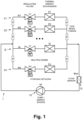
- reference numeral 1 refers to a hydronic network that comprises a plurality of parallel zones Z1, Z2, Zi, Zn.
- the hydronic network 1 includes one or more circuits with fluid transportation lines, e.g. pipes, for transporting a liquid heat transportation medium, e.g. water and/or glycol.
- each of the zones Z1, Z2, Zi, Zn comprises a regulating valve V1, V2, Vi, Vn for regulating the flow of fluid ⁇ 1, ⁇ 2, ⁇ i, ⁇ n through the respective zone Z1, Z2, Zi, Zn.
- the hydronic network 1 further comprises a bypass line in parallel to the zones Z1, Z2, Zi, Zn.
- the bypass line comprises a regulating valve for regulating the flow of fluid through the bypass line.
- the hydronic network 1 shown in Figure 1 is highly simplified and in actual configurations comprises more than four zones Z1, Z2, Zi, Zn, as indicated schematically in Figure 1 , 2, and 3 by periods "".
- the hydronic network 1 further comprises a common source 13, e.g. a motorized pump 13, e.g. in combination with a heater and/or a chiller.
- a common source 13 e.g. a motorized pump 13, e.g. in combination with a heater and/or a chiller.
- the hydronic network 1 includes optionally individual flow sensors arranged in the zones Z1, Z2, Zi, Zn, e.g. with the regulating valves V1, V2, Vi, Vn, for measuring the individual flows of fluid ⁇ 1, ⁇ 2, ⁇ i, ⁇ through the zones Z1, Z2, Zi, Zn or regulating valves V1, V2, Vi, Vn, respectively.
- the zones Z1, Z2, Zi, Zn further include thermal energy exchangers E1, E2, Ei, En, e.g. a heat exchanger for heating the zone Z1, Z2, Zi, Zn or a cooling device for cooling the zone Z1, Z2, Zi, Zn.
- the hydronic network 1 includes a pressure sensor configured and arranged to measure the (differential) system pressure ⁇ P of the hydronic network 1, e.g. the pressure drop over the pump 13 or a thermal energy exchanger E1, E2, Ei, En.
- temperature sensors are arranged in the zones Z1, Z2, Zi, Zn for measuring the supply temperatures T1 sup, T2sup, Tisup, Tnsup and return temperatures T1 ret, T2ret, Tiret, Tnret in the zones Z1, Z2, Zi, Zn, e.g. the supply temperatures T1 sup, T2sup, Tisup, Tnsup of the fluid entering the thermal energy exchangers E1, E2, Ei, En and the return temperatures T1 ret, T2ret, Tiret, Tnret of the fluid exiting the thermal energy exchangers E1, E2, Ei, En.
- At least some of the regulating valves V1, V2, Vi, Vn are implemented as six-way valves which are configured to couple a respective zone Z1, Z2, Zi, Zn and its thermal energy exchanger E1, E2, Ei, En alternatively to a first fluid transportation circuit (driven by a first pump 13) for heating or to a second fluid transportation circuit (driven by a second pump 13) for cooling, and to regulate the flow of fluid ⁇ 1, ⁇ 2, ⁇ i, ⁇ n from the first or second fluid transportation, respectively, through the zone Z1, Z2, Zi, Zn and its thermal energy exchanger E1, E2, Ei, En.
- the hydronic network 1 actually comprises a first hydraulic sub-network, that comprises the first fluid transportation circuit for heating and the zones Z1, Z2, Zi, Zn coupled to the first fluid transportation circuit for heating, and a second hydraulic sub-network, that comprises the second fluid transportation circuit for cooling and the zones Z1, Z2, Zi, Zn coupled to the second fluid transportation circuit for cooling.
- the regulating valves V1, V2, Vi, Vn are driven by (electric) motors M1, M2, Mi, Mn for adjusting the orifice and thus flow of fluid ⁇ 1, ⁇ 2, ⁇ i, ⁇ n through the valve V1, V2, Vi, Vn.
- the motors M1, M2, Mi, Mn are controlled by controllers R1, R2, Ri, Rn that are connected electrically or electromagnetically to the motors M1, M2, Mi, Mn.
- the controllers R1, R2, Ri, Rn each include an electronic circuit, e.g. a programmable processor, an application specific integrated circuit (ASIC), or another logic unit.
- a motor M1, M2, Mi, Mn and a controller R1, R2, Ri, Rn form an actuator in a common actuator housing.
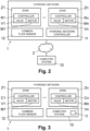
- the actuators or controllers R1, R2, Ri, Rn, respectively, further comprise a communication module configured for wireless and/or wired data communication with an external hydronic network controller 11 and/or a computer system 10.
- the hydronic network controller 11 comprises one or more programmable processors and a data storage system connected to the processor(s).
- the computer system 10 comprises one or more operational computers with one or more programmable processors and a data storage system connected to the processor(s).
- the hydronic network controller 11 and the computer system 10 are configured (programmed) to perform various functions described later in more detail.
- the computer system 10 is arranged on-site, as part of the hydronic network 1 environment, e.g. in the same building or premises, or in a remote location, connected to the hydronic network 1 and/or a hydronic network controller 11 via a communications network 2.
- the communications network 2 includes fixed and/or mobile communications networks, e.g. WLAN (Wireless Local Area Network), GSM (Global System for Mobile Communications), UMTS (Universal Mobile Telephone System), 5G, or other mobile radio networks.
- the communications network 2 includes the Internet and the computer system 10 is implemented as a cloud-based computer system.
- thermo energy exchangers E1, E2, Ei, En are possible sequences of steps performed by the hydronic network controller 11 and/or the computer system 10 for balancing the multi-zone hydronic network 1 or its consumers, i.e. thermal energy exchangers E1, E2, Ei, En, respectively,
- the characteristic parameters are determined for the first hydraulic sub-network, that comprises the zones Z1, Z2, Zi, Zn coupled to the first fluid transportation circuit for heating, and for the second hydraulic sub-network, that comprises the zones Z1, Z2, Zi, Zn coupled to the second fluid transportation circuit for cooling.
- step S1 the computer system 10 determines and records individual flow characteristics IFC for the regulating valves V1, V2, Vi, Vn of the hydronic network 1. More specifically, the computer system 10 determines and records for each of the regulating valves V1, V2, Vi, Vn individual flow characteristics IFC which include, for different valve positions vi of the respective regulating valve Vi, the total flow ⁇ tot measured by the common flow sensor 12, while the remaining other valves V1, V2, Vn of the hydronic network 1 are set to a closed position, consequently, the measured total flow ⁇ tot corresponds to the individual flow ⁇ i through the respective regulating valve Vi and associated zone Zi.
- Figure 6 illustrates an example of the individual flow characteristics IFC for a particular valve Vi.
- step S2 the computer system 10 determines and records combined flow characteristics CFC for the regulating valves V1, V2, Vi, Vn of the hydronic network 1. More specifically, the computer system 10 determines and records for each of the regulating valves V1, V2, Vi, Vn combined flow characteristics CFC which include, for different valve positions vi of the respective regulating valve Vi, the total flow ⁇ tot measured by the common flow sensor 12, while the remaining other valves V1, V2, Vn of the hydronic network 1 are set to an open position. In one embodiment, for determining and recording the combined flow characteristics CFC for a regulating valve Vi, the remaining other valves V1, V2, Vn of the hydronic network 1 are (all) set to a fully open position.
- the remaining other regulating valves V1, V2, Vn of the hydronic network 1 are set to a plurality of various valve positions, in a range from closed valve position to fully open valve position.
- Figures 6 and 7 illustrate examples of the combined flow characteristics CFC for a particular valve Vi.
- step S2 the computer system 10 further determines and records for the regulating valves V1, V2, Vi, Vn of the hydronic network 1 a "complementary" flow of fluid CF which indicates for the respective regulating valve Vi the total flow of fluid ⁇ tot measured by the flow sensor 12 at a closed valve position of the respective regulating valve Vi, while the remaining other regulating valves V1, V2, Vn of the hydronic network 1 are set to the open valve position.
- the "complementary" flow of fluid CF indicates the flow of fluid which flows into the remaining other regulating valves V1, V2, Vn of the hydronic network 1 at their respective open positions when the respective regulating valve Vi is set to a closed valve position.
- Figure 7 illustrates an example of a complementary flow of fluid CF for a particular regulating valve Vi.
- Figure 7 further illustrates the influence of open valve positions of other regulating valves V1, V2, Vn of the hydronic network 1 on the flow of fluid of the respective regulating valve Vi, owing to their interaction/interdependence of shared pipe sections.
- Figure 7 illustrates dependent flow characteristics DFC of the respective regulating valve Vi determined from the "complementary" flow of fluid CF and the combined flow characteristics CFC of the respective regulating valve Vi, e.g. as a result of subtracting (off-setting) the "complementary" flow of fluid CF from the combined flow characteristics CFC of the respective regulating valve Vi.
- the zone interaction defines for a particular regulating valve Vi an area of flow characteristics AFC which is determined by the valve's individual flow characteristics IFC, when all other regulating valves V1, V2, Vn of the hydronic network 1 are closed, and the dependent flow characteristics DFC, when all other regulating valves V1, V2, Vn of the hydronic network 1 are fully open (adjusted by the complementary flow of fluid CF).
- the area of flow characteristics AFC determines the possible flow characteristics of a particular regulating valve Vi depending on the valve positions of the other regulating valves V1, V2, Vn of the hydronic network 1.
- reference numeral DFC* refers to dependent flow characteristics of the particular regulating valve Vi, when the other regulating valves V1, V2, Vn of the hydronic network 1 are set to intermediate positions, e.g. at positions corresponding to valve orifices which are half open (50%).
- step S3 the computer system 10 determines and stores individual correction factors ⁇ i for the regulating valves V1, V2, Vi, Vn, using the individual flow characteristics IFC and the combined flow characteristics CFC of the respective regulating valve V1, V2, Vi, Vn.
- the correction factors ⁇ i reflect the influence on the flow of fluid of a respective regulating valve Vi by the other regulating valves V1, V2, Vn of the hydronic network 1 at their respective valve positions v1, v2, vn.
- the zone-specific correction factors ⁇ i ( v 1 , v 2 , v i ,v n ) are determined iteratively by the computer system 10 applying an objective function to the individual flow characteristics IFC of the regulating valve Vi of the respective zone Zi and the dependent flow characteristics DFC, DFC* of the particular regulating valve Vi.
- the objective function for the zone-specific correction factors ⁇ i ( v 1 , v 2 , v i ,v n ) is defined as: ⁇ i ⁇ i ⁇ i ⁇ ⁇ i ⁇ 1 ⁇ 2 ⁇ i ⁇ n ⁇ i ⁇ i ⁇ 1 ⁇ 2 ⁇ i ⁇ n ⁇ 1 whereby ⁇ i ( v i ) relates to the individual flow characteristics IFC of the particular regulating valve Vi (flow through the particular regulating valve Vi depending on its respective valve positions vi), and ⁇ i ( v 1 , v 2 , v i , v n ) relates to the dependent flow characteristics DFC, DFC* of the particular regulating valve Vi (flow through the particular regulating valve Vi depending on the valve positions v1, v2, vi, vn of the regulating valves V1, V2, Vi, Vn).
- the denominator can be replaced with the value of the measured total flow ⁇ tot_measured , incorporating the measured value into the objective function.
- the computer system 10 iteratively updates the zone-specific correction factors ⁇ i ( v 1 , v 2 , v i , v n ) to achieve the objective function.
- the iterative procedure is ended when an iteration end point or convergence criteria is reached, i.e. when the difference to the objective of "1" is minimized.
- the iterative procedure is ended when the ratio ⁇ i ⁇ i ⁇ i ⁇ i ⁇ ⁇ i ⁇ 1 ⁇ 2 ⁇ i ⁇ n ⁇ i ⁇ i ⁇ 1 ⁇ 2 ⁇ i ⁇ n or ⁇ i ⁇ i ⁇ i ⁇ ⁇ i ⁇ 1 ⁇ 2 ⁇ i ⁇ n ⁇ tot _ measured , respectively, is within the interval [0.99, 1.01]) for all the observed valve positions v1, v2, vi, vn of the regulating valves V1, V2, Vi, Vn of the hydronic network 1.
- the correction factors ⁇ i ( v 1 , v 2 , v i , v n ) are determined by minimizing the objective function which aims at bringing the total flow, predicted based on the correction factors ⁇ i ( v 1 , v 2 , v i ,v n ) the individual flow characteristics IFC, close to the measured total flow ⁇ tot _ measured , as determined by the dependent flow characteristics DFC, DFC*.
- reference numeral DCF refers to the determined correction factor ⁇ i of a particular zone Zi or regulating valve Vi, respectively, being close to "1", for the scenario when all the remaining other regulating valves V1, V2, Vn of the hydronic network 1 are set to a closed position and the particular regulating valve Vi performs in accordance with its individual flow characteristics IFe.
- Reference numeral DCF* refers to the determined correction factor ⁇ i of a particular zone Zi or regulating valve Vi, respectively, for the scenario when all the remaining other regulating valves V1, V2, Vn of the hydronic network 1 are set to fully open position and the particular regulating valve Vi performs in accordance with its (offset) dependent flow characteristics DFC*.
- Reference numeral DCF** refers to the determined correction factor ⁇ i of a particular zone Zi or regulating valve Vi, respectively, for the scenario when the remaining other regulating valves V1, V2, Vn of the hydronic network 1 are set to an intermediate position and the particular regulating valve Vi performs in accordance with its respective dependent flow characteristics DFC ⁇ , depicted in Figure 8 . More specifically, the zone-specific dependency factors ⁇ i are determined iteratively, by the computer system 10 applying an objective function to the individual flow characteristics IFC of the regulating valve Vi of the respective zone Zi and the combined flow characteristics CFC of the particular regulating valve Vi at the valve positions v1, v2, vi, vn of the regulating valves V1, V2, Vi, Vn of the hydronic network 1.
- ⁇ i ⁇ i ( v i ) relates to the individual flow characteristics IFC of the particular regulating valve Vi, and ⁇ tot_ measured relates to the total flow measured for the valve positions v1, v2, vi, vn of the regulating valves V1, V2, Vi, Vn as defined by the combined flow characteristics CFC of the particular regulating valve Vi at the valve positions v1, v2, vi, vn of the regulating valves V1, V2, Vi, Vn of the hydronic network 1.
- the computer system 10 iteratively updates the zone-specific dependency factors ⁇ i to achieve the objective function.
- the iterative procedure is ended when an iteration end point or convergence criteria is reached, i.e. when the difference to the objective of "1" is minimized.
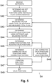
- step S4 the computer system 10 and/or the hydronic network controller 11, use the zone-specific correction factors ⁇ i or dependency factors ⁇ i for balancing the multi-zone hydronic network 1 or its consumers, respectively.
- step S41 the computer system 10 and/or the hydronic network controller 11, respectively, receives setpoints si for the flow of fluid ⁇ i for the regulating valves V1, V2, Vi, Vn of the hydronic network 1.
- step S41 the computer system 10 and/or the hydronic network controller 11, respectively, receives setpoints for thermal energy to be transferred or exchanged in the zone(s) Z1, Z2, Zi, Zn by the respective thermal energy exchangers E1, E2, Ei, En, and determines the setpoints si for the flow of fluid ⁇ i for the regulating valves V1, V2, Vi, Vn, using the thermal energy transfer setpoints si. More specifically, the computer system 10 and/or the hydronic network controller 11, respectively, determines the setpoints si using the thermal energy transfer setpoints and the current thermal energy transfer rates of the thermal energy exchangers E1, E2, Ei, En.
- step S42 the computer system 10 and/or the hydronic network controller 11, respectively, determines and sets individual valve positions v1, v2, vi, vn for the regulating valves V1, V2, Vi, Vn, for the individual setpoints si, using the individual flow characteristics IFC of the regulating valves V1, V2, Vi, Vn.
- step S45 the computer system 10 and/or the hydronic network controller 11, respectively, determines the zone-specific correction factors ⁇ i or dependency factors ⁇ i, using the adjusted valve positions v1, v2, vi, vn.
- step S46 the computer system 10 and/or the hydronic network controller 11, respectively, determines corrected valve positions v1, v2, vi, vn for the regulating valves V1, V2, Vi, Vn, to reflect the mutual influences of the regulating valves V1, V2, Vi, Vn or zones Z1, Z2, Zi, Zn of the hydronic network 1, using the zone-specific correction factors ⁇ i and/or dependency factors ⁇ i, respectively.
- the iteration endpoint is defined as a change threshold which defines a minimum ratio or percentage of change of the valve positions v1, v2, vi, vn in an iteration cycle for the iteration to continue.
- the change threshold is set to 1%, 2% or 5%. If the total ratio of change of the valve positions v1, v2, vi, vn in an iteration cycle is below the change threshold, the iteration end point is reached.
- the iteration end point is reached when a maximum number of performed iteration cycles has been reached. For example, the maximum number of iteration cycles is set to 10, 20, 50 or 100.
- step S48 the computer system 10 and/or the hydronic network controller 11, respectively, continues the iteration process in step S48, using the corrected valve positions v1, v2, vi, vn of step S46 for determining refined zone-specific correction factors ⁇ i and/or dependency factors ⁇ i and further refined corrected valve positions v1, v2, vi, vn in steps S45 and S46.
- step S49 the computer system 10 and/or the hydronic network controller 11, respectively, sets the valve positions v1, v2, vi, vn for the regulating valves V1, V2, Vi, Vn, using the corrected valve positions v1, v2, vi, vn of step S46.
- Dynamic and iterative balancing continues in step S43, by the computer system 10 and/or the hydronic network controller 11, respectively, determining the current balancing factor b, using the total of the setpoints si for the regulating valves V1, V2, Vi, Vn and the current total flow of fluid ⁇ tot _measured , measured for the regulating valves V1, V2, Vi, Vn set to their corrected valve positions v1, v2, vi, vn.
- the hydronic network 1 comprises individual flow sensors arranged in the zones Z1, Z2, Zi, Zn for measuring the individual flows of fluid ⁇ 1, ⁇ 2, ⁇ i, ⁇ n through the zones Z1, Z2, Zi, Zn or regulating valves V1, V2, Vi, Vn, respectively
- the computer system 10 uses the individual flows of fluid ⁇ 1, ⁇ 2, ⁇ i, ⁇ n measured by the individual flow sensors for determining the individual flow characteristics IFC of the respective regulating valves V1, V2, Vi, Vn and the combined flow characteristics CFC of the respective regulating valves V1, V2, Vi, Vn, thereby reducing computation and iteration cycles.
- the hydronic network 1 includes a pressure sensor configured and arranged to measure the (differential) system pressure + ⁇ P of the hydronic network 1, the measured (individual and total) flow values are scaled by the current pressure value ( ⁇ ⁇ ⁇ p ).
Landscapes
- Engineering & Computer Science (AREA)
- General Engineering & Computer Science (AREA)
- Chemical & Material Sciences (AREA)
- Combustion & Propulsion (AREA)
- Mechanical Engineering (AREA)
- Physics & Mathematics (AREA)
- Thermal Sciences (AREA)
- General Physics & Mathematics (AREA)
- Automation & Control Theory (AREA)
- Flow Control (AREA)
Claims (21)
- Procédé d'équilibrage d'un réseau hydronique (1) qui comporte une pluralité de zones parallèles (Z1, Z2, Zi, Zn) avec une soupape de régulation (V1, V2, Vi, Vn) dans chaque zone (Z1, Z2, Zi, Zn) pour réguler un flux de fluide (φ1, φ2, φl, φN, φi, φn) dans toute la zone respective (Z1, Z2, Zi, Zn), ce procédé comprenant :l'utilisation d'un capteur de flux (12) pour mesurer un flux total de fluide (φtot) dans toute la pluralité de zones parallèles (Z1, Z2, Zi, Zn) du réseau hydronique (1) ; etl'enregistrement (S1) dans un ordinateur (10) pour chacune des soupapes de régulation (V1, V2, Vi, Vn), des caractéristiques de de flux individuels (IFC), ces caractéristiques de flux individuels indiquant, pour une soupape de régulation respective (V1, V2, Vi, Vn), le flux total de fluide (φtot) mesuré par le capteur de flux (12) dans différentes positions de soupapes de la soupape de régulation respective (V1, V2, Vi, Vn), tandis que les autres soupapes de régulation restantes du réseau hydronique (1) sont réglées dans une position de soupape fermée ;caractérisé en ce que ce procédé comprend en outre :l'enregistrement (S2) dans l'ordinateur (10) pour chacune des soupapes de régulation (V1, V2, Vi, Vn) de caractéristiques de flux combinés (CFC), ces caractéristiques de flux combinés (CFC) indiquant, pour la soupape de régulation respective (V1, V2, Vi, Vn), le flux total de fluide (φtot) mesuré par le capteur de flux (12) dans différentes positions de soupapes de la soupape de régulation respective (V1, V2, Vi, Vn), tandis que les autres soupapes de régulation restantes (V1, V2, Vi, Vn) du réseau hydronique (1) sont réglées dans une position de soupape ouverte ;la détermination (S3), par l'ordinateur (10), de facteurs de correction (βi) pour chacune des soupapes de régulation (V1, V2, Vi, Vn), en utilisant les caractéristiques de flux individuels (IFC) de la soupape de régulation respective (V1, V2, Vi, Vn) et les caractéristiques de flux combinés (CFC) de la soupape de régulation respective (V1, V2, Vi, Vn) ; etl'équilibrage (S4) du réseau hydronique (1) par l'ordinateur en réglant les positions de soupapes des soupapes de régulation (V1, V2, Vi, Vn), en utilisant des flux cibles (S1, S2, Si, Sn) pour les zones (Z1, Z2, Zi, Zn) et les facteurs de correction (βi) des soupapes de régulation (V1, V2, Vi, Vn).
- Procédé selon la revendication 1, dans lequel l'équilibrage (S4) du réseau hydronique (1) comprend la détermination (S42), par l'ordinateur (10), de positions de soupapes individuelles pour les soupapes de régulation (V1, V2, Vi, Vn), en utilisant les flux cibles (S1, S2, Si, Sn) pour les zones (Z1, Z2, Zi, Zn) et les caractéristiques de flux individuels (IFC) pour les soupapes de régulation (V1, V2, Vi, Vn), et la détermination (S3) des facteurs de correction (βi) pour chacune des soupapes de régulation (V1, V2, Vi, Vn) en utilisant en outre les positions de soupapes individuelles des soupapes de régulation (V1, V2, Vi, Vn) .
- Procédé selon une des revendications 1 ou 2, dans lequel l'équilibrage (S4) du réseau hydronique (1) comprend l'exécution, par l'ordinateur (10), d'un processus d'itération qui comprend la détermination (S45), dans une première étape, de facteurs de correction (βi) pour les soupapes de régulation (V1, V2, Vi, Vn), en utilisant des positions de soupapes individuelles pour les soupapes de régulation (V1, V2, Vi, Vn), la détermination (S46), dans une deuxième étape, de positions de soupapes corrigées pour les soupapes de régulation (V1, V2, Vi, Vn), en utilisant les flux cibles (S1, S2, Si, Sn) pour les zones (Z1, Z2, Zi, Zn) et les facteurs de correction (βi) des soupapes de régulation (V1, V2, Vi, Vn), et la répétition de la première étape et de la deuxième étape, en utilisant (S48) les positions de soupapes corrigées de la deuxième étape comme les positions de soupapes individuelles dans la première étape.
- Procédé selon la revendication 3, dans lequel l'exécution du processus d'itération comprend l'utilisation, par l'ordinateur (10), des positions de soupapes corrigées pour déterminer (S47) si un point final d'itération est atteint ou pas, avant la répétition de la première étape et de la deuxième étape.
- Procédé selon une des revendications 1 à 4, dans lequel l'enregistrement (S2) des caractéristiques de flux combinés (CFC) comprend l'enregistrement, par l'ordinateur (10), pour chacune des soupapes de régulation (V1, V2, Vi, Vn), du flux total de fluide (φtot) mesuré par le capteur de flux (12) dans différentes positions de soupapes de la soupape de régulation respective (V1, V2, Vi, Vn) et dans diverses positions de soupapes des autres soupapes de régulation restantes (V1, V2, Vi, Vn) du réseau hydronique (1), dans une plage depuis une position de soupape fermée à une position de soupape complètement ouverte ; et dans lequel la détermination (S3) des facteurs de correction (βi) comprend la détermination (S3), par l'ordinateur (10), de facteurs de correction (βi) pour chacune des soupapes de régulation (V1, V2, Vi, Vn) pour une pluralité de différentes positions de soupapes des soupapes de régulation (V1, V2, Vi, Vn) du réseau hydronique (1).
- Procédé selon une des revendications 1 à 5, ce procédé comprenant en outre l'enregistrement (S2) dans l'ordinateur (10), pour chacune des soupapes de régulation (V1, V2, Vi, Vn), d'un flux de fluide complémentaire (CF), ce flux de fluide complémentaire (CF) indiquant, pour la soupape de régulation respective (V1, V2, Vi, Vn), le flux total de fluide (φtot) mesuré par le capteur de fluide (12) dans une position de soupape fermée de la soupape de régulation respective (V1, V2, Vi, Vn), tandis que les autres soupapes de régulation restantes (V1, V2, Vi, Vn) du réseau hydronique (1) sont réglées dans la position de soupape ouverte ; et la détermination (S3) des facteurs de correction (βi) comprenant l'utilisation, par l'ordinateur (10), du flux de fluide complémentaire (CF) de la soupape de régulation respective (V1, V2, Vi, Vn) et les caractéristiques de flux combinés (CFC) de la soupape de régulation respective (V1, V2, Vi, Vn).
- Procédé selon une des revendications 1 à 6, ce procédé comprenant en outre le calcul, par l'ordinateur (10), de caractéristiques de flux dépendants (DFC) pour chacune des soupapes de régulation (V1, V2, Vi, Vn), en utilisant les caractéristiques de flux combinés (CFC) de la soupape de régulation respective (V1, V2, Vi, Vn) et le flux total de fluide (φtot) mesuré par le capteur de flux (12) dans une position de soupape fermée de la soupape de régulation respective (V1, V2, Vi, Vn), tandis que les autres soupapes de régulation restantes (V1, V2, Vi, Vn) du réseau hydronique (1) sont réglées dans les positions de soupapes ouvertes ; et la détermination, par l'ordinateur (10), des facteurs de correction (βi) pour chacune des soupapes de régulation (V1, V2, Vi, Vn) en appliquant une fonction objective aux caractéristiques de flux dépendants (DFC) de la soupape de régulation respective (V1, V2, Vi, Vn) et aux caractéristiques de flux individuels (IFC) de la soupape de régulation respective (V1, V2, Vi, Vn).
- Procédé selon une des revendications 1 à 7, dans lequel la détermination (S3) des facteurs de correction (βi) comprend le calcul, par l'ordinateur (10), d'une position de soupape moyenne à partir des positions de soupapes des soupapes de régulation (V1, V2, Vi, Vn) du réseau hydronique (1), et la détermination du facteur de correction (βi) pour la soupape de régulation respective (V1, V2, Vi, Vn) d'une zone particulière (Z1, Z2, Zi, Zn) en utilisant la position de soupape moyenne et un facteur de dépendance spécifique à zone (αi) de la zone particulière (Z1, Z2, Zi, Zn).
- Procédé selon une des revendications 1 à 8, ce procédé comprenant en outre l'utilisation d'un capteur de pression pour mesurer une pression de système courante (Δp) du réseau hydronique (1) ; et la mise à l'échelle, par l'ordinateur (10), du flux total de fluide (φtot) mesuré par le capteur de flux (12), en utilisant la pression de système courante.
- Procédé selon une des revendications 1 à 9, ce procédé comprenant en outre l'utilisation d'un ou de plusieurs capteurs de flux individuels pour mesurer du flux de fluide individuels (φ1, φ2, φ, φn) à travers des soupapes de régulation respectives (V1, V2, Vi, Vn) ; et l'utilisation, par l'ordinateur (10), de flux de fluide individuels (φ1, φ2, φ, φn) mesurés par les capteurs de flux individuels pour déterminer les caractéristiques de flux individuels (IFC) des soupapes de régulation respectives (V1, V2, Vi, Vn) et les caractéristiques de flux combinés (CFC) des soupapes de régulation respectives (V1, V2, Vi, Vn).
- Système informatique (10) pour équilibrer un réseau hydronique (1) qui comprend une pluralité de zones parallèles (Z1, Z2, Zi, Zn) avec une soupape de régulation (V1, V2, Vi, Vn) dans chaque zone (Z1, Z2, Zi, Zn) pour réguler un flux de fluide (Φ1, Φ2, Φi, Φn) à travers la zone respective (Z1, Z2, Zi, Zn), et un capteur de flux (12) pour mesurer un flux total de fluide (φtot) à travers la pluralité de zones parallèles (Z1, Z2, Zi, Zn) du réseau hydronique (1), ce système informatique (10) comprenant un processeur configuré de façon à :recevoir du capteur de flux (12) le flux total de fluide (φtot) à travers la pluralité de zones parallèles (Z1, Z2, Zi, Zn) ; et àenregistrer (S1), pour chacune des soupapes de régulation (V1, V2, Vi, Vn) des caractéristiques de flux individuels (IFC), ces caractéristiques de flux individuels indiquant, pour une soupape de régulation respective (V1, V2, Vi, Vn), le flux total de fluide (φtot) mesuré par le capteur de flux (12) dans différentes positions de soupape de la soupape de régulation respective (V1, V2, Vi, Vn), tandis que les autres soupapes de régulation restantes du réseau hydronique (1) sont réglées dans une position de soupape fermée ;caractérisé en ce que le processeur est configuré en outre de façon à :enregistrer (S2), pour chacune des soupapes de régulation (V1, V2, Vi, Vn) des caractéristiques de flux combinés (CFC), ces caractéristiques de flux combinés (CFC) indiquant pour la soupape de régulation respective (V1, V2, Vi, Vn) le flux total de fluide (φtot) mesuré par le capteur de flux (12) dans différentes positions de soupapes de la soupape de régulation respective (V1, V2, Vi, Vn), tandis que les autres soupapes de régulation restantes (V1, V2, Vi, Vn) du réseau hydronique (1) sont réglées dans une position de soupape ouverte ;déterminer (S3) des facteurs de correction (βi) pour chacune des soupapes de régulation (V1, V2, Vi, Vn), en utilisant les caractéristiques de flux individuels (IFC) de la soupape de régulation respective (V1, V2, Vi, Vn) et les caractéristiques de flux combinés (CFC) de la soupape de régulation respective (V1, V2, Vi, Vn) ; et àéquilibrer (S4) le réseau hydronique (1) en réglant les positions de soupapes des soupapes de régulation (V1, V2, Vi, Vn) en utilisant des flux cibles (S1, S2, Si, Sn) pour les zones (Z1, Z2, Zi, Zn) et les facteurs de correction (βi) des soupapes de régulation (V1, V2, Vi, Vn) .
- Système informatique (10) selon la revendication 11, dans lequel le processeur est configuré de façon à équilibrer (S4) le réseau hydronique (1) en déterminant des positions de soupapes individuelles pour les soupapes de régulation (V1, V2, Vi, Vn), en utilisant les flux cibles (S1, S2, Si, Sn) pour les zones (Z1, Z2, Zi, Zn) et les caractéristiques de flux individuels (IFC) des soupapes de régulation (V1, V2, Vi, Vn), et en déterminant (S3) des facteurs de correction (βi) pour chacune des soupapes de régulation (V1, V2, Vi, Vn), en utilisant en outre les positions de soupapes individuelles des soupapes de régulation (V1, V2, Vi, Vn) .
- Système informatique (10) selon une des revendications 11 ou 12, dans lequel le processeur est configuré de façon à équilibrer (S4) le réseau hydronique (1) en exécutant un processus d'itération qui comprend la détermination, lors d'une première étape, de facteurs de correction (βi) pour les soupapes de régulation (V1, V2, Vi, Vn), en utilisant des positions de soupapes individuelles pour les soupapes de régulation (V1, V2, Vi, Vn), en déterminant, lors d'une deuxième étape, les positions de soupapes corrigées pour les soupapes de régulation (V1, V2, Vi, Vn), en utilisant les flux cibles (S1, S2, Si, Sn) pour les zones (Z1, Z2, Zi, Zn) et les facteurs de correction (βi) des soupapes de régulation (V1, V2, Vi, Vn), et en répétant la première étape et la deuxième étape, en utilisant les positions de soupapes corrigées de la deuxième étape comme les positions de soupapes individuelles dans la première étape.
- Système informatique (10) selon la revendication 13, dans lequel le processeur est configuré de façon à exécuter le processus d'itération en utilisant les positions de soupapes corrigées pour déterminer si un point final d'itération est atteint ou pas, avant de répéter la première étape et la deuxième étape.
- Système informatique (10) selon une des revendications 11 à 14, dans lequel le processeur est configuré de façon à enregistrer (S2) les caractéristiques de flux combinés (CFC) en enregistrant, pour chacune des soupapes de régulation (V1, V2, Vi, Vn), le flux total de fluide (φtot) mesuré par le capteur de flux (12) dans différentes positions de soupapes de la soupape de régulation respective (V1, V2, Vi, Vn) et dans diverses positions de soupapes des autres soupapes de régulation restantes (V1, V2, Vi, Vn) du réseau hydronique (1), dans une plage depuis la position de soupape fermée à la position de soupape ouverte ; et de façon à déterminer (S3) les facteurs de correction (βi) pour chacune des soupapes de régulation (V1, V2, Vi, Vn) pour une pluralité de positions de soupapes différentes des soupapes de régulation (V1, V2, Vi, Vn) du réseau hydronique (1).
- Système informatique (10) selon une des revendications 11 à 15, dans lequel le processeur est configuré de façon à enregistrer (S2), pour chacune des soupapes de régulation (V1, V2, Vi, Vn), un flux de fluide complémentaire (CF), ce flux de fluide complémentaire (CF) indiquant, pour la soupape de régulation respective (V1, V2, Vi, Vn), le flux total de fluide (φtot) mesuré par le capteur de fluide (12) dans une position de soupape fermée de la soupape de régulation respective (V1, V2, Vi, Vn), tandis que les autres soupapes de régulation restantes (V1, V2, Vi, Vn) du réseau hydronique (1) sont réglées dans la position de soupape ouverte ; et de façon à déterminer (S3) les facteurs de correction (βi) en utilisant le flux de fluide complémentaire (CF) de la soupape de régulation respective (V1, V2, Vi, Vn) et les caractéristiques de flux combinés (CFC) de la soupape de régulation respective (V1, V2, Vi, Vn).
- Système informatique (10) selon une des revendications 11 à 16, dans lequel le processeur est configuré en outre de façon à calculer des caractéristiques de flux dépendantes (DFC) pour chacune des soupapes de régulation (V1, V2, Vi, Vn), en utilisant les caractéristiques de flux combinés (CFC) de la soupape de régulation respective (V1, V2, Vi, Vn) et le flux total de fluide (φtot) mesuré par le capteur de flux (12) dans une position de soupape fermée de la soupape de régulation respective (V1, V2, Vi, Vn), tandis que les autres soupapes de régulation restantes (V1, V2, Vi, Vn) du réseau hydronique (1) sont réglées dans les positions de soupapes ouvertes ; et de façon à déterminer (S3) les facteurs de correction (βi) pour chacune des soupapes de régulation (V1, V2, Vi, Vn) en appliquant une fonction objective aux caractéristiques de flux dépendants (DFC) de la soupape de régulation respective (V1, V2, Vi, Vn) et aux caractéristiques de flux individuels (IFC) de la soupape de régulation respective (V1, V2, Vi, Vn).
- Système informatique (10) selon une des revendications 11 à 17, dans lequel le processeur est configuré de façon à déterminer (S3) les facteurs de correction (βi) en calculant une position de soupape moyenne à partir des positions de soupapes des soupapes de régulation (V1, V2, Vi, Vn) du réseau hydronique (1), et en déterminant le facteur de correction (βi) pour la soupape de régulation respective (V1, V2, Vi, Vn) d'une zone particulière (Z1, Z2, Zi, Zn) en utilisant la position de soupape moyenne et un facteur de dépendance spécifique à zone (αi) de la zone particulière (Z1, Z2, Zi, Zn).
- Système informatique (10) selon une des revendications 11 à 18, dans lequel le processeur est configuré de façon à recevoir d'un capteur de pression une pression de système courante (Δp) du réseau hydronique (1) ; et de façon à mettre à l'échelle le flux total de fluide (φtot) mesuré par le capteur de flux (12), en utilisant la pression de système courante.
- Système informatique (10) selon une des revendications 11 à 19, le processeur étant configuré de façon à recevoir d'un ou de plusieurs capteurs de flux individuels des flux de fluide individuels (φ1, φ2, φ, φn) à travers des soupapes de régulation respectives (V1, V2, Vi, Vn) ; et de façon à utiliser les flux de fluide individuels (φ1, φ2, φ, φn) venant des capteurs de flux individuels pour déterminer les caractéristiques de flux individuels (IFC) pour les soupapes de régulation respectives (V1, V2, Vi, Vn) et les caractéristiques de flux combinés (CFC) des soupapes de régulation respectives (V1, V2, Vi, Vn).
- Produit de programme informatique comprenant un support non transitoire lisible par ordinateur où est stocké un code programme informatique configuré de façon à commander un ou plusieurs processeurs d'un système informatique (10) pour équilibrer un réseau hydronique (1) qui comporte une pluralité de zones parallèles (Z1, Z2, Zi, Zn) avec une soupape de régulation (V1, V2, Vi, Vn) dans chaque zone (Z1, Z2, Zi, Zn) pour réguler un flux de fluide (φ1, φ2, φ1, φn) à travers la zone respective (Z1, Z2, Zi, Zn), et un capteur de flux (12) pour mesurer un flux total de fluide (φtot) à travers la pluralité de zones parallèles (Z1, Z2, Zi, Zn) du réseau hydronique (1) de manière à ce que le système informatique (10) :reçoive du capteur de flux (12) le flux total de fluide (φtot) à travers la pluralité de zones parallèles (Z1, Z2, Zi, Zn) ; etenregistre (S1) pour chacune des soupapes de régulation (V1, V2, Vi, Vn) des caractéristiques de flux individuels (IFC), ces caractéristiques de flux individuels indiquant, pour une soupape de régulation respective (V1, V2, Vi, Vn), le flux total de fluide (φtot) mesuré par le capteur de flux (12) dans différentes positions de soupape de la soupape de régulation respective (V1, V2, Vi, Vn), tandis que les autres soupapes de régulation restantes (V1, V2, Vi, Vn) du réseau hydronique (1) sont réglées dans une position fermée ;caractérisé en ce que ce produit de programme informatique est configuré en outre de façon à commander le ou les processeurs du système informatique (10) de manière à ce que le système informatique (10) enregistre (S2) pour chacune des soupapes de régulation (V1, V2, Vi, Vn) des caractéristiques de flux combinés (CFC), ces caractéristiques de flux combinés (CFC) indiquant, pour la soupape de régulation respective (V1, V2, Vi, Vn), le flux total de fluide (φtot) mesuré par le capteur de flux (12) dans différentes positions de soupape de la soupape de régulation respective (V1, V2, Vi, Vn), tandis que les autres soupapes de régulation restantes (V1, V2, Vi, Vn) du réseau hydronique (1) sont réglées dans une position ouverte ;détermine (S3) les facteurs de correction (βi) pour chacune des soupapes de régulation (V1, V2, Vi, Vn), en utilisant les caractéristiques de flux individuels (IFC) de la soupape de régulation respective (V1, V2, Vi, Vn) et les caractéristiques de flux combinés (CFC) de la soupape de régulation respective (V1, V2, Vi, Vn) ; etéquilibre (S4) le réseau hydronique (1) en réglant les positions de soupapes des soupapes de régulation (V1, V2, Vi, Vn), en utilisant des flux cibles (S1, S2, Si, Sn) pour les zones (Z1, Z2, Zi, Zn) et les facteurs de correction (βi) des soupapes de régulation (V1, V2, Vi, Vn) .
Applications Claiming Priority (2)
| Application Number | Priority Date | Filing Date | Title |
|---|---|---|---|
| CH9282019 | 2019-07-22 | ||
| PCT/EP2020/064545 WO2021013406A1 (fr) | 2019-07-22 | 2020-05-26 | Procédé et système d'équilibrage d'un réseau hydronique |
Publications (2)
| Publication Number | Publication Date |
|---|---|
| EP4004446A1 EP4004446A1 (fr) | 2022-06-01 |
| EP4004446B1 true EP4004446B1 (fr) | 2023-06-21 |
Family
ID=67480069
Family Applications (1)
| Application Number | Title | Priority Date | Filing Date |
|---|---|---|---|
| EP20729670.8A Active EP4004446B1 (fr) | 2019-07-22 | 2020-05-26 | Procédé et système d'équilibrage d'un réseau hydronique |
Country Status (4)
| Country | Link |
|---|---|
| US (1) | US12044427B2 (fr) |
| EP (1) | EP4004446B1 (fr) |
| CN (1) | CN114222891B (fr) |
| WO (1) | WO2021013406A1 (fr) |
Families Citing this family (3)
| Publication number | Priority date | Publication date | Assignee | Title |
|---|---|---|---|---|
| GB2602459B (en) * | 2020-12-23 | 2022-12-28 | Idzv Ltd | A hydraulic unit |
| WO2023007332A1 (fr) * | 2021-07-29 | 2023-02-02 | Ariston S.P.A. | Procédé d'équilibrage hydraulique de système de chauffage d'espace |
| PL444714A1 (pl) * | 2023-04-30 | 2024-11-04 | Vemmio Spółka Z Ograniczoną Odpowiedzialnością | System sterowania inteligentnym budynkiem oraz metoda sterowania inteligentnym budynkiem |
Family Cites Families (24)
| Publication number | Priority date | Publication date | Assignee | Title |
|---|---|---|---|---|
| US5325884A (en) * | 1991-07-10 | 1994-07-05 | Conservair Technologies | Compressed air control system |
| FR2746168B1 (fr) | 1996-03-14 | 1998-04-30 | Procede d'equilibrage d'un reseau de distribution de fluide non compressible a deux tubes, a plusieurs branches ou colonnes derivees | |
| DE19912588A1 (de) | 1999-03-20 | 2000-09-21 | Ksb Ag | Fluidtransportsystem |
| FR2870927B1 (fr) * | 2004-05-26 | 2007-10-05 | Patrick Delpech | Procede d'equilibrage des emetteurs d'une installation de chauffage |
| DE102008003315A1 (de) * | 2008-01-07 | 2009-07-09 | Viessmann Werke Gmbh & Co Kg | Heizungsanlage und Verfahren zum Betrieb einer Heizungsanlage |
| US8024161B2 (en) | 2008-08-19 | 2011-09-20 | Honeywell International Inc. | Method and system for model-based multivariable balancing for distributed hydronic networks |
| DE102008039525A1 (de) | 2008-08-23 | 2010-04-15 | Honeywell Technologies Sarl | System zum Kühlen oder Heizen und Anordnung zum hydraulischen Abgleichen eines wasser- oder dampfführenden System zum Kühlen oder Heizen |
| US8109289B2 (en) * | 2008-12-16 | 2012-02-07 | Honeywell International Inc. | System and method for decentralized balancing of hydronic networks |
| DE102009011522B4 (de) * | 2009-03-06 | 2018-03-08 | Viessmann Werke Gmbh & Co Kg | Verfahren zur Analyse eines Rohrnetzes einer Heizungsanlage |
| CH705143A1 (de) * | 2011-06-30 | 2012-12-31 | Belimo Holding Ag | Verfahren und Vorrichtungen zum Abgleichen einer Gruppe von Verbrauchern in einem Fluidtransportsystem. |
| US20130048114A1 (en) * | 2011-08-26 | 2013-02-28 | Optimum Energy, Llc | Controlled hydronic distribution system |
| AT513733A1 (de) | 2012-10-30 | 2014-06-15 | Vaillant Group Austria Gmbh | Verfahren zum hydraulischen Abgleich eines Heizungssystems |
| CN103017253A (zh) * | 2012-12-06 | 2013-04-03 | 鞍山市海汇自动化有限公司 | 一种集中供热全网热平衡控制方法 |
| CH707402A2 (de) * | 2012-12-18 | 2014-06-30 | Belimo Holding Ag | Verfahren und Vorrichtung zum Abgleichen einer Gruppe von Verbrauchern in einem Fluidtransportsystem. |
| EP2846103B1 (fr) * | 2013-09-05 | 2018-01-31 | Aeris Soluciones De Control, S.L. | Procédé de régulation pour la régulation d'un système de conditionnement d'air |
| WO2016086986A1 (fr) * | 2014-12-03 | 2016-06-09 | Grundfos Holding A/S | Ensemble convertisseur électronique à des fins de montage en rattrapage sur une partie externe d'un boîtier d'une unité de pompage |
| US9864383B2 (en) * | 2015-04-02 | 2018-01-09 | Belimo Holding Ag | Method and system for determining characteristic parameters of a hydraulic network |
| EP3168541B1 (fr) * | 2015-11-16 | 2019-02-27 | Danfoss A/S | Équilibrage de charge de chauffage |
| DE102015121418B3 (de) * | 2015-12-09 | 2017-03-16 | Oventrop Gmbh & Co. Kg | Verfahren zum automatischen hydraulischen Abgleich von Verbrauchern in einer Heizungs- und/oder Kühlanlage |
| CN205878298U (zh) * | 2016-06-13 | 2017-01-11 | 北京同怀远洋科贸有限公司 | 全自动补偿法平衡调节装置 |
| US11047582B2 (en) * | 2016-06-22 | 2021-06-29 | Belimo Holding Ag | Method and devices for controlling a fluid transportation network |
| CN110234933B (zh) | 2016-11-22 | 2021-10-26 | 贝利莫控股公司 | 液体循环系统及用于操作此液体循环系统的方法 |
| CN206669841U (zh) * | 2017-04-11 | 2017-11-24 | 北京合利能科技有限公司 | 自吸平衡供热系统 |
| CN207394967U (zh) * | 2017-08-02 | 2018-05-22 | 中清源环保节能有限公司 | 一种供热二次网智能节能与平衡控制系统 |
-
2020
- 2020-05-26 CN CN202080052494.1A patent/CN114222891B/zh active Active
- 2020-05-26 EP EP20729670.8A patent/EP4004446B1/fr active Active
- 2020-05-26 WO PCT/EP2020/064545 patent/WO2021013406A1/fr not_active Ceased
- 2020-05-26 US US17/607,508 patent/US12044427B2/en active Active
Also Published As
| Publication number | Publication date |
|---|---|
| US12044427B2 (en) | 2024-07-23 |
| EP4004446A1 (fr) | 2022-06-01 |
| CN114222891B (zh) | 2023-12-05 |
| CN114222891A (zh) | 2022-03-22 |
| US20220196250A1 (en) | 2022-06-23 |
| WO2021013406A1 (fr) | 2021-01-28 |
Similar Documents
| Publication | Publication Date | Title |
|---|---|---|
| EP3278032B1 (fr) | Procédé et système pour déterminer des paramètres caractéristiques d'un réseau hydraulique | |
| EP4004446B1 (fr) | Procédé et système d'équilibrage d'un réseau hydronique | |
| EP2997430B1 (fr) | Dispositif et procédé permettant de commander l'ouverture d'une vanne dans un système de chauffage/climatisation | |
| EP2641027B1 (fr) | Dispositif et procédé de commande de l'ouverture d'une soupape dans un système hvac | |
| TWI406119B (zh) | 用以在一區域內遠端控制壓力的系統及一化學機械研磨機系統 | |
| EP3483690B1 (fr) | Procédé de régulation d'un écoulement de fluide à travers une soupape | |
| CN100407083C (zh) | 流测量模块和方法 | |
| DK2726792T3 (en) | Method and device for balancing a group of consumers in a fluidtransportsystem | |
| US20100147394A1 (en) | System and method for decentralized balancing of hydronic networks | |
| CN101484858A (zh) | 流量控制阀的控制方法和控制系统 | |
| CN104995458A (zh) | 用于平衡在流体运输系统中的负载的组的方法和装置 | |
| US20100300540A1 (en) | Method for operating a network of pipes | |
| KR102755306B1 (ko) | 다채널 질량 유량 및 유량비 제어 시스템을 위한 방법 및 장치 | |
| KR101753891B1 (ko) | 배수지 유입 밸브 및 병렬 운전 펌프의 제어 장치 및 제어 방법 | |
| EP3475623B1 (fr) | Procédé et dispositifs de réglage de réseau de transport de fluide | |
| CN112540629A (zh) | 一种智能阀门流量标定方法及装置 | |
| KR20080084192A (ko) | 난방시스템 및 난방제어방법 | |
| EP2846103B1 (fr) | Procédé de régulation pour la régulation d'un système de conditionnement d'air | |
| AU767765B2 (en) | Method and apparatus for optimizing environmental temperature for a device under test | |
| CN117193395B (zh) | 一种多通道流量比例分配方法和系统 | |
| CN102794310B (zh) | 轧制模型优化装置 | |
| KR100898097B1 (ko) | 유량계 없는 난방시스템 및 난방제어방법 | |
| DK1754005T3 (en) | Methods for balancing the emitters of a heating system, | |
| JP2008077575A (ja) | 流体の温度制御装置及び方法 | |
| EP3798520B1 (fr) | Dérivation à commande électronique |
Legal Events
| Date | Code | Title | Description |
|---|---|---|---|
| STAA | Information on the status of an ep patent application or granted ep patent |
Free format text: STATUS: UNKNOWN |
|
| STAA | Information on the status of an ep patent application or granted ep patent |
Free format text: STATUS: THE INTERNATIONAL PUBLICATION HAS BEEN MADE |
|
| PUAI | Public reference made under article 153(3) epc to a published international application that has entered the european phase |
Free format text: ORIGINAL CODE: 0009012 |
|
| STAA | Information on the status of an ep patent application or granted ep patent |
Free format text: STATUS: REQUEST FOR EXAMINATION WAS MADE |
|
| 17P | Request for examination filed |
Effective date: 20220113 |
|
| AK | Designated contracting states |
Kind code of ref document: A1 Designated state(s): AL AT BE BG CH CY CZ DE DK EE ES FI FR GB GR HR HU IE IS IT LI LT LU LV MC MK MT NL NO PL PT RO RS SE SI SK SM TR |
|
| DAV | Request for validation of the european patent (deleted) | ||
| DAX | Request for extension of the european patent (deleted) | ||
| GRAP | Despatch of communication of intention to grant a patent |
Free format text: ORIGINAL CODE: EPIDOSNIGR1 |
|
| STAA | Information on the status of an ep patent application or granted ep patent |
Free format text: STATUS: GRANT OF PATENT IS INTENDED |
|
| INTG | Intention to grant announced |
Effective date: 20230228 |
|
| GRAS | Grant fee paid |
Free format text: ORIGINAL CODE: EPIDOSNIGR3 |
|
| GRAA | (expected) grant |
Free format text: ORIGINAL CODE: 0009210 |
|
| STAA | Information on the status of an ep patent application or granted ep patent |
Free format text: STATUS: THE PATENT HAS BEEN GRANTED |
|
| AK | Designated contracting states |
Kind code of ref document: B1 Designated state(s): AL AT BE BG CH CY CZ DE DK EE ES FI FR GB GR HR HU IE IS IT LI LT LU LV MC MK MT NL NO PL PT RO RS SE SI SK SM TR |
|
| REG | Reference to a national code |
Ref country code: CH Ref legal event code: EP |
|
| REG | Reference to a national code |
Ref country code: DE Ref legal event code: R096 Ref document number: 602020012785 Country of ref document: DE |
|
| P01 | Opt-out of the competence of the unified patent court (upc) registered |
Effective date: 20230601 |
|
| REG | Reference to a national code |
Ref country code: AT Ref legal event code: REF Ref document number: 1581129 Country of ref document: AT Kind code of ref document: T Effective date: 20230715 |
|
| REG | Reference to a national code |
Ref country code: IE Ref legal event code: FG4D |
|
| REG | Reference to a national code |
Ref country code: LT Ref legal event code: MG9D |
|
| REG | Reference to a national code |
Ref country code: NL Ref legal event code: MP Effective date: 20230621 |
|
| PG25 | Lapsed in a contracting state [announced via postgrant information from national office to epo] |
Ref country code: SE Free format text: LAPSE BECAUSE OF FAILURE TO SUBMIT A TRANSLATION OF THE DESCRIPTION OR TO PAY THE FEE WITHIN THE PRESCRIBED TIME-LIMIT Effective date: 20230621 Ref country code: NO Free format text: LAPSE BECAUSE OF FAILURE TO SUBMIT A TRANSLATION OF THE DESCRIPTION OR TO PAY THE FEE WITHIN THE PRESCRIBED TIME-LIMIT Effective date: 20230921 |
|
| REG | Reference to a national code |
Ref country code: AT Ref legal event code: MK05 Ref document number: 1581129 Country of ref document: AT Kind code of ref document: T Effective date: 20230621 |
|
| PG25 | Lapsed in a contracting state [announced via postgrant information from national office to epo] |
Ref country code: RS Free format text: LAPSE BECAUSE OF FAILURE TO SUBMIT A TRANSLATION OF THE DESCRIPTION OR TO PAY THE FEE WITHIN THE PRESCRIBED TIME-LIMIT Effective date: 20230621 Ref country code: NL Free format text: LAPSE BECAUSE OF FAILURE TO SUBMIT A TRANSLATION OF THE DESCRIPTION OR TO PAY THE FEE WITHIN THE PRESCRIBED TIME-LIMIT Effective date: 20230621 Ref country code: LV Free format text: LAPSE BECAUSE OF FAILURE TO SUBMIT A TRANSLATION OF THE DESCRIPTION OR TO PAY THE FEE WITHIN THE PRESCRIBED TIME-LIMIT Effective date: 20230621 Ref country code: LT Free format text: LAPSE BECAUSE OF FAILURE TO SUBMIT A TRANSLATION OF THE DESCRIPTION OR TO PAY THE FEE WITHIN THE PRESCRIBED TIME-LIMIT Effective date: 20230621 Ref country code: HR Free format text: LAPSE BECAUSE OF FAILURE TO SUBMIT A TRANSLATION OF THE DESCRIPTION OR TO PAY THE FEE WITHIN THE PRESCRIBED TIME-LIMIT Effective date: 20230621 Ref country code: GR Free format text: LAPSE BECAUSE OF FAILURE TO SUBMIT A TRANSLATION OF THE DESCRIPTION OR TO PAY THE FEE WITHIN THE PRESCRIBED TIME-LIMIT Effective date: 20230922 |
|
| PG25 | Lapsed in a contracting state [announced via postgrant information from national office to epo] |
Ref country code: FI Free format text: LAPSE BECAUSE OF FAILURE TO SUBMIT A TRANSLATION OF THE DESCRIPTION OR TO PAY THE FEE WITHIN THE PRESCRIBED TIME-LIMIT Effective date: 20230621 |
|
| PG25 | Lapsed in a contracting state [announced via postgrant information from national office to epo] |
Ref country code: SK Free format text: LAPSE BECAUSE OF FAILURE TO SUBMIT A TRANSLATION OF THE DESCRIPTION OR TO PAY THE FEE WITHIN THE PRESCRIBED TIME-LIMIT Effective date: 20230621 |
|
| PG25 | Lapsed in a contracting state [announced via postgrant information from national office to epo] |
Ref country code: ES Free format text: LAPSE BECAUSE OF FAILURE TO SUBMIT A TRANSLATION OF THE DESCRIPTION OR TO PAY THE FEE WITHIN THE PRESCRIBED TIME-LIMIT Effective date: 20230621 |
|
| PG25 | Lapsed in a contracting state [announced via postgrant information from national office to epo] |
Ref country code: IS Free format text: LAPSE BECAUSE OF FAILURE TO SUBMIT A TRANSLATION OF THE DESCRIPTION OR TO PAY THE FEE WITHIN THE PRESCRIBED TIME-LIMIT Effective date: 20231021 |
|
| PG25 | Lapsed in a contracting state [announced via postgrant information from national office to epo] |
Ref country code: SM Free format text: LAPSE BECAUSE OF FAILURE TO SUBMIT A TRANSLATION OF THE DESCRIPTION OR TO PAY THE FEE WITHIN THE PRESCRIBED TIME-LIMIT Effective date: 20230621 Ref country code: SK Free format text: LAPSE BECAUSE OF FAILURE TO SUBMIT A TRANSLATION OF THE DESCRIPTION OR TO PAY THE FEE WITHIN THE PRESCRIBED TIME-LIMIT Effective date: 20230621 Ref country code: RO Free format text: LAPSE BECAUSE OF FAILURE TO SUBMIT A TRANSLATION OF THE DESCRIPTION OR TO PAY THE FEE WITHIN THE PRESCRIBED TIME-LIMIT Effective date: 20230621 Ref country code: PT Free format text: LAPSE BECAUSE OF FAILURE TO SUBMIT A TRANSLATION OF THE DESCRIPTION OR TO PAY THE FEE WITHIN THE PRESCRIBED TIME-LIMIT Effective date: 20231023 Ref country code: IS Free format text: LAPSE BECAUSE OF FAILURE TO SUBMIT A TRANSLATION OF THE DESCRIPTION OR TO PAY THE FEE WITHIN THE PRESCRIBED TIME-LIMIT Effective date: 20231021 Ref country code: ES Free format text: LAPSE BECAUSE OF FAILURE TO SUBMIT A TRANSLATION OF THE DESCRIPTION OR TO PAY THE FEE WITHIN THE PRESCRIBED TIME-LIMIT Effective date: 20230621 Ref country code: EE Free format text: LAPSE BECAUSE OF FAILURE TO SUBMIT A TRANSLATION OF THE DESCRIPTION OR TO PAY THE FEE WITHIN THE PRESCRIBED TIME-LIMIT Effective date: 20230621 Ref country code: CZ Free format text: LAPSE BECAUSE OF FAILURE TO SUBMIT A TRANSLATION OF THE DESCRIPTION OR TO PAY THE FEE WITHIN THE PRESCRIBED TIME-LIMIT Effective date: 20230621 Ref country code: AT Free format text: LAPSE BECAUSE OF FAILURE TO SUBMIT A TRANSLATION OF THE DESCRIPTION OR TO PAY THE FEE WITHIN THE PRESCRIBED TIME-LIMIT Effective date: 20230621 |
|
| PG25 | Lapsed in a contracting state [announced via postgrant information from national office to epo] |
Ref country code: PL Free format text: LAPSE BECAUSE OF FAILURE TO SUBMIT A TRANSLATION OF THE DESCRIPTION OR TO PAY THE FEE WITHIN THE PRESCRIBED TIME-LIMIT Effective date: 20230621 |
|
| REG | Reference to a national code |
Ref country code: DE Ref legal event code: R097 Ref document number: 602020012785 Country of ref document: DE |
|
| PLBE | No opposition filed within time limit |
Free format text: ORIGINAL CODE: 0009261 |
|
| STAA | Information on the status of an ep patent application or granted ep patent |
Free format text: STATUS: NO OPPOSITION FILED WITHIN TIME LIMIT |
|
| PG25 | Lapsed in a contracting state [announced via postgrant information from national office to epo] |
Ref country code: DK Free format text: LAPSE BECAUSE OF FAILURE TO SUBMIT A TRANSLATION OF THE DESCRIPTION OR TO PAY THE FEE WITHIN THE PRESCRIBED TIME-LIMIT Effective date: 20230621 |
|
| PG25 | Lapsed in a contracting state [announced via postgrant information from national office to epo] |
Ref country code: SI Free format text: LAPSE BECAUSE OF FAILURE TO SUBMIT A TRANSLATION OF THE DESCRIPTION OR TO PAY THE FEE WITHIN THE PRESCRIBED TIME-LIMIT Effective date: 20230621 |
|
| 26N | No opposition filed |
Effective date: 20240322 |
|
| PG25 | Lapsed in a contracting state [announced via postgrant information from national office to epo] |
Ref country code: SI Free format text: LAPSE BECAUSE OF FAILURE TO SUBMIT A TRANSLATION OF THE DESCRIPTION OR TO PAY THE FEE WITHIN THE PRESCRIBED TIME-LIMIT Effective date: 20230621 Ref country code: IT Free format text: LAPSE BECAUSE OF FAILURE TO SUBMIT A TRANSLATION OF THE DESCRIPTION OR TO PAY THE FEE WITHIN THE PRESCRIBED TIME-LIMIT Effective date: 20230621 |
|
| PG25 | Lapsed in a contracting state [announced via postgrant information from national office to epo] |
Ref country code: BG Free format text: LAPSE BECAUSE OF FAILURE TO SUBMIT A TRANSLATION OF THE DESCRIPTION OR TO PAY THE FEE WITHIN THE PRESCRIBED TIME-LIMIT Effective date: 20230621 |
|
| PG25 | Lapsed in a contracting state [announced via postgrant information from national office to epo] |
Ref country code: BG Free format text: LAPSE BECAUSE OF FAILURE TO SUBMIT A TRANSLATION OF THE DESCRIPTION OR TO PAY THE FEE WITHIN THE PRESCRIBED TIME-LIMIT Effective date: 20230621 |
|
| PG25 | Lapsed in a contracting state [announced via postgrant information from national office to epo] |
Ref country code: MC Free format text: LAPSE BECAUSE OF FAILURE TO SUBMIT A TRANSLATION OF THE DESCRIPTION OR TO PAY THE FEE WITHIN THE PRESCRIBED TIME-LIMIT Effective date: 20230621 |
|
| PG25 | Lapsed in a contracting state [announced via postgrant information from national office to epo] |
Ref country code: LU Free format text: LAPSE BECAUSE OF NON-PAYMENT OF DUE FEES Effective date: 20240526 |
|
| GBPC | Gb: european patent ceased through non-payment of renewal fee |
Effective date: 20240526 |
|
| PG25 | Lapsed in a contracting state [announced via postgrant information from national office to epo] |
Ref country code: MC Free format text: LAPSE BECAUSE OF FAILURE TO SUBMIT A TRANSLATION OF THE DESCRIPTION OR TO PAY THE FEE WITHIN THE PRESCRIBED TIME-LIMIT Effective date: 20230621 Ref country code: LU Free format text: LAPSE BECAUSE OF NON-PAYMENT OF DUE FEES Effective date: 20240526 |
|
| REG | Reference to a national code |
Ref country code: BE Ref legal event code: MM Effective date: 20240531 |
|
| PG25 | Lapsed in a contracting state [announced via postgrant information from national office to epo] |
Ref country code: IE Free format text: LAPSE BECAUSE OF NON-PAYMENT OF DUE FEES Effective date: 20240526 |
|
| PG25 | Lapsed in a contracting state [announced via postgrant information from national office to epo] |
Ref country code: BE Free format text: LAPSE BECAUSE OF NON-PAYMENT OF DUE FEES Effective date: 20240531 |
|
| PG25 | Lapsed in a contracting state [announced via postgrant information from national office to epo] |
Ref country code: FR Free format text: LAPSE BECAUSE OF NON-PAYMENT OF DUE FEES Effective date: 20240531 |
|
| PG25 | Lapsed in a contracting state [announced via postgrant information from national office to epo] |
Ref country code: GB Free format text: LAPSE BECAUSE OF NON-PAYMENT OF DUE FEES Effective date: 20240526 |
|
| PGFP | Annual fee paid to national office [announced via postgrant information from national office to epo] |
Ref country code: DE Payment date: 20250519 Year of fee payment: 6 |
|
| PGFP | Annual fee paid to national office [announced via postgrant information from national office to epo] |
Ref country code: CH Payment date: 20250601 Year of fee payment: 6 |
|
| PG25 | Lapsed in a contracting state [announced via postgrant information from national office to epo] |
Ref country code: HU Free format text: LAPSE BECAUSE OF FAILURE TO SUBMIT A TRANSLATION OF THE DESCRIPTION OR TO PAY THE FEE WITHIN THE PRESCRIBED TIME-LIMIT; INVALID AB INITIO Effective date: 20200526 |
|
| PG25 | Lapsed in a contracting state [announced via postgrant information from national office to epo] |
Ref country code: CY Free format text: LAPSE BECAUSE OF FAILURE TO SUBMIT A TRANSLATION OF THE DESCRIPTION OR TO PAY THE FEE WITHIN THE PRESCRIBED TIME-LIMIT; INVALID AB INITIO Effective date: 20200526 |