EP4004481B1 - Système de canon porté pour armes à feu - Google Patents
Système de canon porté pour armes à feu Download PDFInfo
- Publication number
- EP4004481B1 EP4004481B1 EP20845880.2A EP20845880A EP4004481B1 EP 4004481 B1 EP4004481 B1 EP 4004481B1 EP 20845880 A EP20845880 A EP 20845880A EP 4004481 B1 EP4004481 B1 EP 4004481B1
- Authority
- EP
- European Patent Office
- Prior art keywords
- barrel
- gas
- shroud
- porting
- portholes
- Prior art date
- Legal status (The legal status is an assumption and is not a legal conclusion. Google has not performed a legal analysis and makes no representation as to the accuracy of the status listed.)
- Active
Links
Images















Classifications
-
- F—MECHANICAL ENGINEERING; LIGHTING; HEATING; WEAPONS; BLASTING
- F41—WEAPONS
- F41A—FUNCTIONAL FEATURES OR DETAILS COMMON TO BOTH SMALLARMS AND ORDNANCE, e.g. CANNONS; MOUNTINGS FOR SMALLARMS OR ORDNANCE
- F41A21/00—Barrels; Gun tubes; Muzzle attachments; Barrel mounting means
- F41A21/32—Muzzle attachments or glands
- F41A21/36—Muzzle attachments or glands for recoil reduction ; Stabilisators; Compensators, e.g. for muzzle climb prevention
-
- F—MECHANICAL ENGINEERING; LIGHTING; HEATING; WEAPONS; BLASTING
- F41—WEAPONS
- F41C—SMALLARMS, e.g. PISTOLS, RIFLES; ACCESSORIES THEREFOR
- F41C3/00—Pistols, e.g. revolvers
- F41C3/14—Revolvers
Definitions
- the present invention relates to firearms, and more particularly to a ported barrel system which compensates for muzzle rise and recoil when discharging the firearm.
- muzzle rise is particularly prevalent in handguns since the user grasps the hand grip in a position below the centerline of the barrel bore through which the projectile is fired. This creates a moment about the user's hand, thereby resulting in an increased tendency for the barrel to rise after each shot. Muzzle rise however still occurs with shouldered long guns. Muzzle rise adversely affects the point of aim requiring the user to expend more time and effort between shots to reacquire the target and aim the firearm back down field for the follow up shot each time the firearm is discharged.
- An improved barrel system is needed which effectively compensates for both recoil and muzzle rise while preserving a compact firearm profile and offering ease of assembly.
- the gas portholes may be arranged in a 360 degree array around the top, bottom, and both lateral sides of the barrel in one embodiment, or optionally an alternative detachable porting device comprising the same array of gas portholes may be removably coupled to the muzzle end of the barrel in various embodiments.
- the gas portholes may be substantially uniformly or equally arranged and spaced apart around entire circumference of the barrel or porting device to produce uniform gas flow and less disturbance or unbalanced forces on the axially exiting projectile (e.g. bullet or slug) from the barrel, thereby advantageously resulting in better shooting accuracy.
- One or multiple gas plenums may be provided in various embodiments.
- One or more gas discharge ports are formed in the shroud for venting the combustion gases from the collection plenum in a controlled manner to atmosphere to control and minimize muzzle rise.
- the gases are vented transversely and perpendicularly to the longitudinal axis of the firearm barrel.
- the discharge ports preferably may be formed on the upper half of the shroud to compensate for muzzle rise.
- the ports vent gas outward, and in some embodiments preferably in a generally upward direction.
- a two-piece shroud may be provided comprising a fixed rear portion and a detachable front portion or cap.
- the shroud cap encircles the gas portholes of a detachable muzzle brake and includes the one or more discharge ports. Both the detachable shroud cap and muzzle brake greatly facilitate cleaning carbon deposits from each contained in the vented combustion gases which accumulate over time on surfaces exposed to the gases.
- the muzzle brake feature of the barrel porting system may be either integral with the barrel being formed as a unitary structural part thereof, or a separate detachable device in fluid communication with the barrel bore.
- the vertically acting dynamic forces associated with muzzle rise which act in an upwards direction are counterbalanced by the vertically acting downward forces by the gas jetted from the discharge port(s).
- the combined effect of the muzzle brake and muzzle rise features provides a smoother and controlled firing experience to the user which advantageously results in greater accuracy.
- a thread-less coupling system may be provided which detachably secures the porting device such as a muzzle brake to the barrel.
- the thread-less muzzle brake coupling system is designed to be less prone to loosening after repeated firings to preserve the integrity of the gas seals and eliminate the need to retighten the muzzle brake.
- the muzzle brake may be threaded onto the barrel.
- the present barrel porting system is adaptable and usable for handguns (e.g. revolvers and pistols) and long guns (e.g. rifles, shotguns, etc.). Accordingly, the barrel porting system is not limited in its applicability.
- a barrel porting system for a firearm comprises: a barrel including a longitudinal axis, a muzzle end, and an axially extending barrel bore which defines a projectile pathway; a detachable porting device removably coupled to the barrel, the porting device comprising a plurality of gas portholes in fluid communication with the barrel bore; an elongated outer shroud encircling the porting device, the shroud including at least one gas discharge port arranged to vent combustion gas from firing the firearm in an outwards direction; and an annular gas collection plenum formed between the shroud and porting device, the plenum configured to collect gas from the gas portholes and discharge the gas through the at least one discharge port in the shroud.
- a barrel porting system for a firearm comprises: a barrel including a longitudinal axis, a muzzle end, and an axially extending barrel bore which defines a projectile pathway; a plurality of gas portholes formed in a venting portion of the barrel in fluid communication with the barrel bore; and an outer shroud encircling at least the venting portion of the barrel, the shroud including at least one gas discharge port in fluid communication with the gas portholes of the barrel and arranged to vent combustion gas from firing the firearm in a generally upwards direction.
- a barrel porting system for a firearm comprises: a frame or receiver; a barrel supported by the frame or receiver and including a longitudinal axis, a muzzle end, and an axially extending barrel bore which defines a projectile pathway; a detachable porting device removably coupled to the barrel, the porting device comprising a plurality of gas portholes in fluid communication with the barrel bore; an elongated outer shroud encircling the barrel, the shroud comprising a rear shroud portion coupled to the frame or receiver and a front shroud cap detachably coupled to the rear shroud portion; the shroud cap including at least one gas discharge port arranged to vent combustion gases from firing the firearm in a generally upwards direction; and an annular gas collection channel formed between the shroud cap and porting device, the channel operable to collect gas from the gas portholes and discharge the gas through the at least one discharge port in the shroud.
- a method for porting gas from a firearm comprises: providing a firearm including a barrel including an axially extending barrel bore which defines a projectile pathway, and a muzzle device coupled to the barrel and in fluid communication with the barrel bore; firing the firearm; radially discharging combustion gas from the barrel bore through an array of gas portholes in the muzzle device; receiving the gas in an annular gas plenum defined by the muzzle device, the gas collection plenum extending 360 degrees around a circumference of the muzzle device; and discharging the gas from the gas collection plenum through at least one gas discharge port formed in an outer shroud surrounding the muzzle device.
- any ranges disclosed herein are used as shorthand for describing each and every value that is within the range. Any value within the range can be selected as the terminus of the range.
- FIGS. 1 and 2 depict one non-limiting example of a firearm in the form of a revolver which includes an embodiment of the present barrel porting system.
- the firearm illustrated is a revolver, the invention is not so limited. Accordingly, it will be appreciated by one skilled in the art that the barrel porting system may be used on other types of firearms with equal benefit in which it is desirable to reduce felt recoil and muzzle rise.
- the revolver 20 generally includes a frame 21 supporting a barrel 22 and trigger-actuated firing mechanism 23.
- the frame When in the form of a handgun such as the illustrated revolver or alternatively a pistol, the frame generally includes a vertically elongated rear grip portion or tang 23 for attaching the grip 24 for grasping.
- the portion of the frame which supports the barrel 22 may alternatively be considered and referred to as a "receiver" in the art.
- the receiver which supports the barrel is typically a separate part which is mounted to the frame in some manner.
- the terms "frame” and “receiver” may therefore be used interchangeably when referring to the portion of the revolver or pistol which supports the barrel.
- the trigger-actuated firing mechanism 25 operates to discharge the firearm in a known conventional manner.
- the firing mechanism may generally comprise a movable trigger 26 slideably or pivotably mounted to the frame and spring-biased striking member which may be a pivotable hammer 27 as shown operably coupled to the trigger directly or via an intermediate mechanical trigger linkage (e.g. sear, trigger bar, etc.).
- the hammer 27 is configured and arranged to strike a firing pin 28 slideably disposed in the frame.
- the firing pin has a front tip which is projectable in a forward direction when struck by the hammer to in turn strike the percussion cap on a chambered cartridge. Pulling the trigger cocks and releases the hammer to strike the firing pin and discharge the firearm.
- Such revolver firing mechanisms are well known in the art without further elaboration.
- a conventional semi-automatic pistol (not shown) having an axially reciprocatable slide mounted on the frame in a known manner, it bears noting the mechanical linkage may be a rotatable sear.
- the sear is configured and operable to hold the spring-biased hammer or alternatively a spring-biased linearly movable striker in a rearward cocked and ready-to-fire position until the trigger is pulled. Pulling the trigger with a closed breech rotates the sear and releases the cocked hammer or striker to strike the firing pin. The firing pin in turn strikes a chambered cartridge and discharges the pistol.
- a pistol firing mechanism is well known in the art without further elaboration.
- the barrel 22 includes a front muzzle end 30 and an opposite rear breech end 31 (seen in FIG. 5 ).
- the breech end may be coupled to the frame 21, such as via a threaded coupling between the barrel and frame in one non-limiting embodiment. Other non-threaded means may be used to couple the barrel to the frame in other embodiments.
- a longitudinally extending bore 32 is defined between the ends of the barrel which forms a projectile pathway for a bullet or slug.
- the centerline of the barrel bore defines a longitudinal axis LA and axial direction.
- the bore 32 may be rifled or unrifled in various embodiments.
- a breech area 35 (or simply "breech") is defined at the rear end of barrel.
- the rear breech end is located forward and adjacent to a revolving cylinder 29 rotatably carried by frame 21 and which includes a plurality of rotatable cartridge chambers 29a each configured for holding a cartridge in typical fashion.
- the cylinder is rotated via operation of a pawl operably connected to and movable with the trigger mechanism, and sprocket or ratchet assembly on the rear of the cylinder engaged by the pawl each time the trigger is pulled. This rotates a different chamber with cartridge into axial alignment with the barrel bore each time the trigger is pulled.
- Such pawl and sprocket/ratchet mechanisms for revolvers are well known in the art.
- the slide includes a forward facing breech face which creates a closed breech when in battery with the rear breech end of the barrel for firing the pistol, or an open breech for extracting/ejecting spent cartridge casings and loading fresh cartridges into a chamber formed at the breech end of the barrel when spaced rearward from the barrel.
- a reciprocating bolt mounted in the receiver forms the axially reciprocating breech face which performs the forgoing functions.
- Either type of pistol are well known in the art without further elaboration or illustration and usable with the present barrel porting system.
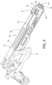
- FIGS. 3-8 depict various views of a first embodiment of a barrel porting system according to the present disclosure which includes the muzzle brake portion of the system directly integrated into the barrel.
- the muzzle brake feature or aspect of the barrel porting system which comprises the array of radial gas portholes 33 is formed (e.g. drilled or otherwise machined or cast) integrally and directly in the muzzle end 30 portion of the barrel body as a unitary structural portion thereof.
- the "fixed" barrel porting system comprises the radially vented barrel 22 and longitudinally elongated outer shroud 40 which circumferentially encircles at least a portion of the barrel.
- a plurality of gas portholes 33 are formed in a forward venting portion of the barrel preferably proximate to and immediately rearward of the muzzle end 30.
- the portholes are arrayed circumferentially 360 degrees around the barrel 22 and define a "fixed" muzzle brake integrally formed as part of the barrel.
- the portholes 33 may have a circular shape as shown in one embodiment; however, other non-polygonal shapes including oval or polygonal shapes may be used in other embodiments.
- the portholes preferably may be uniformly and evenly spaced apart around the circumference and longitudinally from each other on the venting portion for uniform gas flow extraction from the barrel 22 and distribution.
- the portholes 33 may be arranged for example without limitation in three longitudinally spaced apart rings or circular arrays CA of holes around the circumference of the barrel. More or less circular arrays of portholes may be used in other embodiments.
- At least one porthole 33 is preferably formed in the top, bottom, and each opposing right and left side of the barrel (the right and left designations being from the shooter's perspective holding the firearm and looking forward towards the muzzle end of the barrel).
- the spacing and arrangement of portholes 33 may be non-uniform.
- each circular array CA may be circumferentially staggered in location from the portholes in each adjacent circular array (see, e.g. FIG. 17 showing removable muzzle device further described elsewhere), or may be substantially circumferentially aligned with each other in every circular array such that a reference line drawn parallel to longitudinal axis LA through a porthole in one circular array may at least partially intersect a porthole in at least one adjacent circular array (see, e.g. FIG. 6 ).
- Each porthole 33 is radially oriented and in fluid communication with the barrel bore 32 for drawing a portion of the combustion gases off in a direction transverse to the longitudinal axis.
- the centerline CL of the portholes may intersect and are perpendicularly oriented to the longitudinal axis.
- the centerlines of some or all of the portholes 33 may be acutely angled to the longitudinal axis LA and/or offset therefrom such that the centerlines do not intersect the longitudinal axis.
- the portholes 33 When the radial gas portholes 33 are formed directly in a rifles barrel 22 in the fixed barrel porting system, the portholes preferably may be located within and directly through the longitudinally-extending rifling grooves 36 as shown in FIG. 6 . This protects the portholes from wear by the slug or bullet as it travels down the barrel bore 32.
- the gas portholes 33 need not necessarily be located within the rifling grooves. Accordingly, other embodiments may have the gas portholes located through the full thickness of the barrel 22.
- the outer shroud 40 preferably has an axial (longitudinal) length which covers at least the venting portion of the barrel adjacent to its muzzle end as shown. In one embodiment, the shroud 40 may extend for a majority, or substantially the entire length of the barrel. When the barrel 22 is axially inserted into the shroud, the outwardly open gas portholes 33 become enclosed by the shroud.
- the shroud 40 generally includes an open front end 41, open rear end 42, and a generally circumferential wall 45 circumscribing the barrel 22 and extending longitudinally between the ends along longitudinal axis LA of the firearm.
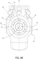
- Circumferential wall 45 may have any suitable cross-sectional shape or profile (see, e.g. FIG. 4B ) including portions such as the downward extension shown which is spaced distally from the barrel 22.
- the cross-sectional shape may in part be dictated by the frame 21 to provide a substantially uniform and pleasing visual appearance.
- the rear end 42 may be abutted to the firearm frame 21 and secured in place on the firearm by any suitable means.
- the shroud 40 defines an axially-extending open internal longitudinal cavity 45 between the ends configured to slideably receive the barrel therein.
- the longitudinal cavity 45 may be complementary configured and dimensioned to the barrel to form a relatively tight fit with the barrel thereby avoiding any substantial annular gaps or space between at least the forward portion of the barrel and interior surface of the shroud to reduce vibration or chatter when firing the firearm.
- the shroud 40 can accommodate various accessories. As shown, the shroud 40 may be configured with a front sight mounting interface for detachably or permanently mounting a front sight 47 thereto. In one embodiment, the interface may comprise a transversely oriented full or partial dovetail slot 47a which receives a mating dovetail protrusion 47b formed on the bottom of the sight. In other embodiments, a fixed sight integrally formed with the shroud 40 may be provided.
- the shroud may further include accessory rails 46 (e.g. Picatinny or other) on the top and/or bottom in certain embodiments.
- the barrel porting system in one embodiment further includes an enlarged circumferentially extending annular gas collection channel 37 defining a gas collection plenum 34 between barrel 22 and the shroud 40.
- the channel/plenum circumscribes the barrel and extends a full 360 around its exterior.
- the channel 37 may be recessed into the exterior surface of the barrel, and may be formed by a reduced diameter intermediate portion of the barrel which defines a circumferentially-extending recessed band which defines the annular plenum 34 (see, e.g. FIG. 8 ).
- the channel 37 may be bounded at its front and rear by full diameter portions of the barrel that interface with the interior surface of the shroud 40 to form front and rear gas seals 130, 131.
- Each gas porthole 33 in the barrel 22 is preferably formed within the gas collection channel 37 so that the annular gas collection plenum 34 receives gas directly from the barrel bore 32 exiting through the portholes 33 when the firearm is fired.
- the gas portholes 33 are therefore in direct fluid communication with the annular gas collection channel 37 and defined plenum 34.
- the channel 37 is longitudinally broad having a greater axial length than at least twice its radial depth, and preferably in some embodiments greater than at least three times its depth.
- the axial length of the barrel recessed channel 37 and concomitantly the gas collection plenum 34 may vary depending on the number and longitudinal spacing of the array of gas portholes provided in the barrel so that each porthole is preferably located within and radially vents directly into the channel from the barrel bore to minimize pressure drop and maximize the amount of combustion gas extracted from the barrel bore.
- the recessed channel 37 is not merely an interface space between the barrel 22 and interior surface of shroud 40. Instead, the channel 37 which defines plenum 34 has a pronounced depth which is sufficient to collect a large volume of high pressure combustion gas extracted from the barrel bore 32 via gas portholes 33, and distribute that gas to the discharge port(s) 44 in shroud 40.
- the annular gas collection plenum 34 may instead be formed on the interior surface of the shroud 40 by providing the circumferentially-extending recessed channel in the shroud in lieu of the barrel 22.
- the barrel may have a constant diameter where the gas portholes 33 are formed.
- Each gas porthole 33 in this case is preferably still located so that the portholes lie adjacent to the gas collection plenum 34 for venting combustion gases directly and radially into the plenum.
- the annual gas collection plenum 34 may be formed in either the barrel or shroud with equal performance effect and benefit.
- combustion gas entering the gas collection plenum 34 from the barrel gas portholes 33 circulates in a circumferential direction around the entire 360 degree circumference of the barrel within the plenum. This advantageously increases the volume of gas which can be bled off of the barrel when the firearm is fired to minimize felt recoil.
- one or more gas discharge ports 44 are formed through the upper half of the shroud 40 above longitudinal axis LA from its interior surface to its exterior surface.
- a plurality of discharge ports may be provided in which each port is in direct fluid communication with the annular gas collection plenum 34 (see, e.g. FIGS. 3-7 ).
- the ports may be in the form of elongated longitudinal slots.
- a pair of angularly separated discharge ports 44 may be provided in the shroud which are symmetrically arranged around a reference vertical centerline axis Cv of the barrel (see, e.g. FIG. 7 ). This arrangement is advantageous in that it preserves the ability to mount the front sight directly to the shroud between the ports 44 .
- the centerlines of discharge ports 44 may be angularly separated from each other by an angle of about and including 60 to 90 degrees as shown in FIG. 4B (when viewing the shroud from the muzzle end 30 of the barrel 22 looking rearward).
- a radial centerline Rc extending through each discharge port 44 which originates at the longitudinal axis LA may be angled at angle A1 between about and including 30 to 45 degrees to the vertical centerline axis Cv of the barrel (shown in FIG. 4B ).
- Other angular orientations may be used; however, the discharge ports should preferably located on only the top half of the barrel shroud for countering muzzle rise.
- an enlarged single gas discharge port in the form of a longitudinal elongated slot may be disposed on top dead center of the shroud which is in direct fluid communication with the annular gas collection plenum 34.
- additional gas discharge ports may be formed in the shroud at and/or below the longitudinal axis LA in the lower half of the shroud 40 to further reduce felt recoil.
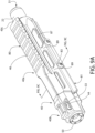
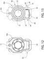
- the detachable muzzle brake comprises the same radial gas portholes 33 previously described herein with respect to the embodiment of FIGS. 3-8 , albeit the pattern or arrangement may differ as shown.
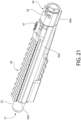
- the gas portholes 33 in detachable muzzle brake 50 may be arranged in a single circumferentially-extending circular array CA in a circumferentially staggered pattern in which the centerline CL each porthole is vertically and longitudinally offset from each of two adjacent portholes in the array (best shown in FIGS. 21 and 24 ).
- the staggered pattern allows more portholes to be tightly packed together while still allowing sufficient spacing between portholes to avoid adversely affecting the structural integrity of the muzzle brake 50 to withstand the higher combustion gas pressure to which it is exploded during firing the firearm.
- the centerlines CL may be circumferentially aligned as shown in the embodiment of FIG. 6 .
- a plurality of circular arrays CA may be provided analogously to the embodiment shown in FIG. 6 .
- the gas collection channel may instead be formed on the interior surface of the shroud 40.
- each gas porthole 33 is preferably still formed in the barrel so that the portholes lie adjacent to the gas collection channel 37/plenum 34 for venting combustion gases directly and radially into the channel/plenum.
- the detachable muzzle brake 50 may therefore have a relatively constant outside diameter. Accordingly, the gas collection channel 37 may be formed in either the barrel or shroud with equal performance effect and benefit.
- the gas discharge ports 44 in shroud 40 may be in the form of a pair of elongated longitudinal slots arranged on either side of front sight 47, similar to those shown in FIGS. 3-8 previously described herein.
- the ports are arranged to intersect and receive gas from the gas collection channel 37 and defined plenum 34.
- the gas discharge slots each have a length at least coextensive with the axial length of the gas collection channel. This ensures minimum resistance to gas flow and pressure drop across the discharge ports which in turn maximizes the volumetric gas flow that can be vented by the barrel porting system to atmosphere each time the firearm is fired.
- the slots may nonetheless have an axial length less than that of the gas collection channel/plenum.
- an enlarged single cross-wise gas discharge port 44 in the form of an elongated slot may be disposed on top dead center of the shroud 40 which is in direct fluid communication with the gas collection channel 37/plenum 34.
- the single slot the slot may be located forward of front sight as shown, or may be located immediately to the rear of the front sight mounting interface on the shroud in other embodiments not depicted.
- the slot may extend across the top of the shroud cap and partially downwards along its sides as shown.
- the slot is still preferably disposed on the upper half of the shroud cap 40b to compensate for upward directed muzzle rise forces when the firearm is discharged. Accordingly, at least some of the upper gas portholes formed in the muzzle brake 50 within the gas collection channel/plenum may be exposed and visible through the discharge slot.
- the muzzle brake may be threadably coupled to the barrel by providing internal threads on the rear portion of the muzzle brake which engage mating external threads on a portion of the front muzzle end 30 of the barrel (see, e.g. FIGS. 22A and 25 ).
- Various unthreaded coupling means are described herein which alternatively may be used..
- the two-piece shroud includes a rear shroud portion 40a and a removable front shroud portion or cap 40b which is configured for easy mounting to and detachment from the firearm to facilitate routine cleaning of the detachable muzzle brake 50 without removing the rear shroud portion.
- the rear shroud portion is configured for more permanent or semi-permanent securement to the firearm frame which in some embodiments may provide at least partial support to the axially elongated barrel 22.
- the rear shroud portion 40a therefore has an axial (longitudinal) length which extends for a majority of the entire length of the barrel (except for the breech end 31 received in an axial frontal opening of the firearm frame 21and the distal muzzle end 30.
- the muzzle end 30 of barrel 22 may project forwardly from the front end of the rear shroud portion 40a for coupling the muzzle brake 50 thereto and to help support and coupled the front shroud cap 40b thereto.
- the rear shroud portion 40a and/or barrel 22 may be mounted to and cantilevered from the front portion of the firearm frame 22 similar to the arrangement shown in FIG. 2 .
- the barrel is nested inside the rear shroud portion 40a.
- the rear breech end 31 of the barrel may be received in a front opening of frame 21 formed by a circular axial bore 55 which extends rearwards into the cylinder opening of the frame, which is open laterally.
- the axial bore 55 may be threaded in one embodiment to rotatably engage external threads on the barrel rear breech end 31. Other types of unthreaded coupling arrangements between the barrel and frame may be used however.
- the breech end of the barrel lies adjacent to the cylinder chambers to receive a projectile (e.g.
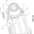
- the rear end of the rear shroud portion 40a abuttingly engages the front face of the frame 21, and may include a rearwardly extending anti-rotation mounting tab 40c at top dead center ( FIG. 24 ) or another location which enters a corresponding forwardly open and complementary configured socket 40d ( FIG. 2 ) in the frame 21.
- the tab 40c may have any suitable polygonal or non-polygonal shape, including for example cylindrical, rectilinear, hexagonal, etc.
- the rear shroud portion 40a may be secured in place to the frame 21 by the threaded coupling between the muzzle brake 50 and barrel 22 when the entire shroud and muzzle brake assembly is coupled to the firearm. As shown in FIG. 24 , the rear shroud portion 40a is trapped between the front face of frame 21 and the rear end of the front shroud cap 40b. Other arrangement may be used.
- the front shroud cap 40b comprises a generally tubular body in one embodiment including an open front end 58, an open rear end 59, sidewalls 60, and an axially extending longitudinal passage 61 between and through the ends for mounting the muzzle brake therein (see, e.g. FIGS. 22 and 24-25 ).
- the cap may be polygonal or non-polygon in external configuration or profile and cross-sectional shape.
- the longitudinal passage 61 may have a cross-sectional shape which is complementary configured to the cross-sectional shape of the muzzle brake (e.g. circular).
- the shroud cap 40b may be complementary configured to the external profile or shape of the rear portion 40a of the shroud 40 to provide a uniform and pleasing external appearance.
- the external profile of both portions of the shroud may be octagonal; however, other cross-sectional profile shapes may be provided.
- the front shroud cap 40b includes an internal annular protrusion 62 which projects radially inward into the longitudinal passage of the cap.
- the protrusion in turn defines an annular mounting shoulder 63 inside the longitudinal passage 61 of the cap proximate to or at its rear end (best shown in FIG. 25 ).
- the shoulder 63 defines a forward facing bearing surface which abuttingly engages the rear end 52 of the muzzle brake 50 when mounted to the firearm (see, e.g. FIG. 25 ).
- the rear end 59 of the shroud cap 40b in turn abuttingly engages an annular protrusion 64 formed on the barrel which in turn abuttingly engages an annular shoulder 65 on the front end of the separate rear portion 40a of the shroud 40.
- the muzzle brake 50 When the muzzle brake 50 is threaded onto the threaded front muzzle end 30 of barrel 22, the muzzle brake compresses annular mounting shoulder 63 of front shroud cap 40b against the barrel annular protrusion 64, which in turn compresses the rear end of fixed shroud portion 40a against the front end of the frame 21 at the rear end of barrel 22.
- This dual action both secures the rear shroud portion 40a and front shroud cap 40b to the firearm. Both a portion of the front shroud cap 40b and the rear shroud portion 40a are thus trapped between the muzzle brake 50 and frame 21.
- the muzzle end 30 of barrel 22 includes an externally threaded front extension which rotatably engages internal threads formed inside the rear end 52 of muzzle brake.
- the rear shroud portion 40a is first slid rearward over the barrel 22 until rear end 40e of shroud portion 40a abuttingly engages the front end of frame 21 (see, e.g. FIGS. 2 and 21-25 ).
- the rear anti-rotation mounting tab 40c at top dead center ( FIG. 24 ) enters corresponding forwardly open socket 40d in frame 21.
- the process continues by sliding the front shroud cap 40b rearward over the threaded front muzzle end extension of the barrel until the cap abuttingly engages the annular protrusion 64 of the barrel 22.
- the muzzle brake is inserted through the open front end 58 of the shroud cap and threaded onto the front extension of the barrel.
- the rear end of the muzzle brake abuttingly engages the annular mounting shoulder 63 inside of the shroud cap 40b as previously described herein, thereby forcing it rearward to increase engagement with the rear fixed portion 40a of the shroud 40.
- the internal annular protrusion 62 of the shroud cap which defines mounting shoulder 63 is trapped between the rear end of the muzzle brake and the barrel annular protrusion 64, and in some embodiments as shown in FIG. 25 also the front end 40f of the rear shroud portion 40a, thereby locking the shroud cap in place.
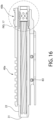
- the longitudinal passage of the front shroud cap 40b and central passageway 53 of the muzzle brake 50 are concentrically and axially aligned with the barrel bore 32 (and longitudinal axis LA defined by the bore centerline).
- the central passageway of the muzzle brake creates a contiguous projectile passageway with the barrel bore (see, e.g. FIG. 9 ).
- the front portion of muzzle brake 50 may protrude forward beyond the front end 58 of the front shroud cap 40b.
- the exposed portion of the front shroud cap 40b may have a tooling configuration such as hex shaped for engaging a tool (e.g. hex wrench or ratchet socket) for tightening the muzzle brake onto the barrel 22.
- a tool e.g. hex wrench or ratchet socket
- Other tooling configurations may be used.
- the shroud cap and muzzle brake are removed from the firearm by simply reversing the foregoing assembly process.
- an optional axially oriented spring-biased anti-rotation plunger 70 may be movably mounted to the front end of the fixed rear shroud portion 40a in a forwardly open axial bore 71 of the shroud.
- the plunger engages a plurality of circumferentially spaced locking teeth 72 which encircle the muzzle end 30 of the barrel 22 immediately rearward of the threaded front extension.
- Teeth 72 may be formed on an annular protrusion of barrel 22 extending radially outward.
- the plunger 70 is biased towards by spring 73 and engages one of the plural recesses formed between the teeth 72 to prevent the barrel from rotating relative to the shroud and the frame when the threaded muzzle brake is unscrewed from the muzzle end of the barrel for removal and cleaning. Because the rear end of the fixed rear shroud portion is rotationally locked to the frame as previously described herein, locking the barrel in turn to the rear shroud portion via the anti-rotation plunger prevents the barrel from rotating and unscrewing at its threaded connection to the frame.
- the lower section 81 may have a laterally smaller/narrower width than the lateral width of the upper section 80 due to the fact that the width of the upper section is dictated in part by the diameter of the barrel.
- An inwardly concave and narrow waist or transition section 87 is formed between the upper and lower sections 80, 81.
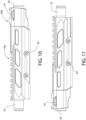
- the upper section 80 of rear shroud portion 40a is punctuated by a plurality of laterally open and longitudinally elongated windows 88 on each side.
- the windows further allow heat to be dissipated from the barrel 22 when firing the firearm and reduces the weight of rear shroud portion 40a.
- the windows 88 are separated from each other by narrow vertical web portions 89 which may have a longitudinal width smaller than the longitudinal width of the windows.
- the rear shroud portion 40a may be formed of a suitably strong metallic or polymeric material (e.g. glass reinforced nylon or other).
- a suitably strong metallic or polymeric material e.g. glass reinforced nylon or other.
- the design of the shroud including the foregoing windows/openings provides the desired degree of flexibility to deform the shroud and clampingly engage the barrel when the cross bolting assemblies 83 are tightened.
- a suitable light gauge metal such as aluminum may be used for rear shroud portion 40a.
- front shroud cap 40b is preferably formed of a suitable metal (e.g. steel , etc.) in the present and other embodiments described herein to better resist erosive wear resulting from the jetting combustion gases to which the cap is exposed.
- rear shroud portion 40a In use when assembling the shroud, rear shroud portion 40a is slid over barrel 22 in the manner previously described herein.
- the cross bolt assemblies 83 may be in a loosened condition. Once fully rearward engaged with the frame 21, the cross bolting assemblies 83 are tightened which compresses the externally disposed heads of the sleeve nut and bolt against the lateral sides of the lower section of the rear shroud portion 40a. This causes the transition sections 87 on each lateral side of rear shroud portion 40a to deform and deflect inwards to compressively clamp the upper section 80 firmly onto and against the barrel 22.
- the natural resiliency and elastic memory of the rear shroud portion 40a material will attempt to spring back to its original undeformed state, thereby advantageously keeping the cross bolting assemblies 53 under tension and tightened after repeating firings of the firearm.
- FIGS. 27-30 depict various views of a third embodiment of a barrel porting system according to the present disclosure having a detachable barrel porting system.
- This third embodiment is similar to and includes many of the same features as the previous detachable muzzle brake system shown in FIGS. 21-25 and described herein.
- the similarities include a two-piece shroud (front shroud cap 40b and rear shroud portion 40a), rear anti-rotation mounting tab 40c at top dead center of the rear end of rear shroud portion 40a which engages the corresponding forwardly open and complementary configured socket 40d ( FIG.
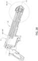
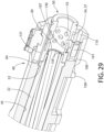
- FIGS. 27-30 depict various views of a fourth embodiment of a barrel porting system according to the present disclosure having a detachable barrel porting system.
- This fourth embodiment is similar to and includes many of the same features as the previous detachable muzzle brake systems shown in FIGS. 9A-20B and 21-25 described herein. Accordingly, similar details and features will not be repeated here again for the sake of brevity. The discussion which follows therefore describes some of the different aspects of present fourth embodiment.
- shroud 40 is a one-piece monolithic structure of unitary construction in lieu of a two-piece shroud (front shroud cap 40b and rear shroud portion 40a).
- the present shroud for the fourth embodiment may be similar to the one-piece shroud 40 shown in FIGS. 1-8 and previously described herein and includes axially-extending open internal longitudinal cavity 45 to slideably receive the barrel 22 therein.
- Muzzle brake 50 in the fourth embodiment is held in place by a wedge assembly comprising a wedge insert 100 received in a downwardly open wedge cavity 102 formed in the forward portion of the shroud 40.
- Wedge insert 100 may have a generally block-shaped body including a threaded longitudinal bore 106 which may be extend completely through the body, and an upwardly extending entrapment projection 107.
- a threaded cylindrical set screw 101 threadably engages the bore 106 and includes a front tooling end configure for engaging a tool, such as a hex screwdriver or key.
- the wedge insert is held in place inside wedge cavity 102 by a bottom closure plate 109 which may be threadably attached to the shroud 40 in one embodiment via screws 105 engaging threaded holes 104 in the bottom of the shroud.
- a bottom closure plate 109 may be threadably attached to the shroud 40 in one embodiment via screws 105 engaging threaded holes 104 in the bottom of the shroud.
- Other ways to removably attach closure plate 109 to the shroud may be used.
- the shroud 40 is first inserted over the barrel 22 and slid fully rearward to abuttingly engage firearm frame 21 in the manner previously described herein.
- the muzzle brake 50 is first inserted through the open front end of the shroud 40 and fully into longitudinal cavity 45 (parallel to longitudinal axis LA) until the rear end 52 of muzzle brake abuttingly engages the radially extending annular protrusion 64 formed on the barrel.
- the wedge insert 100 is provided with the set screw 101 threaded completely inside the insert. Wedge insert 100 is then inserted from below shroud 40 into the forward-most portion of the wedge cavity 102.
- Entrapment projection 107 becomes abuttingly engaged with annular shoulder 108 formed on the inside of muzzle brake 50 which defines a forward facing bearing surface which engages the rear bearing surface on the projection (best shown in FIG. 29 ).
- the cylindrical set screw 101 is then accessed through a forwardly open tooling hole 110 formed through the front end of shroud 40, and rotated to linearly draw the set screw axially forward so that it emerges from longitudinal bore 106 and project forwards from wedge insert 100.
- the set screw 101 abuttingly engages the rear face of the front portion of the shroud adjacent hole 110. This engagement locks and stabilizes the wedge insert 100 in the shroud thereby providing rigidity to the assemblage.
- the plug 101 may be accessed through tooling hole 110 formed through the front end in the shroud.
- the closure plate 109 is then fastened onto shroud 40 to secure the wedge insert 100 in place.
- the front muzzle end 31 of the barrel is recessed within the shroud 40 and spaced rearwards from the front end of the shroud by an axial distance suitable to preserve space within the shroud internal longitudinal cavity 45 for mounting the detachable muzzle brake 50 at least partially therein.
- the wedge insert entrapment projection 107 may be disposed within the channel 37 and gas collection plenum 34 formed inside the shroud. Accordingly, the top edge of the projection 107 may be arcuately curved to complement the curvature of the muzzle brake body within the channel 37.
- the muzzle brake 50 cannot be axially withdrawn forward from the internal longitudinal cavity 45 of the shroud due to blocking and interference between the shroud annular retention surface and the screw.
- the foregoing process or method steps are simply reversed.
- the front end of the muzzle brake may protrude slightly forward from the shroud and its internal longitudinal cavity as shown.
- FIG. 26 depicts a fifth embodiment of a barrel porting system according to the present disclosure having a detachable barrel porting system.
- This fifth embodiment is similar to and includes many of the same features as the previous detachable muzzle brake system with single-piece shroud 40 of the fourth embodiment shown in FIGS. 27-30 .
- the wedge assembly is replaced by a thread-less muzzle brake coupling system comprises a threaded set screw 120 which acts by wedging action to retain the muzzle brake 50 in the shroud.
- the set screw engages a threaded transversely open radial bore 122 formed in the bottom of the shroud 40 proximate to its open front end.
- Set screw 120 includes a proximal head configured to engage a tool (e.g. hex wrench or screwdriver) and a conical distal end which extends transversely through the shroud 40.
- the screw extends completely through the bottom wall of the shroud 40 into the rear portion of the outward facing circumferential gas collection channel 37/plenum 34 on the exterior surface of the muzzle brake 50.
- the conical distal end defines an angled wedge-shaped bearing surface which slideably engages a complementary angled annular retention bearing surface 121 which faces forwardly on the muzzle brake.
- the retention bearing surface 121 is formed at the rear end of the gas collection channel in the muzzle brake in certain embodiments. Both mating bearing surfaces are obliquely angled to the longitudinal axis LA of the barrel bore of the firearm.
- the muzzle brake 50 is inserted rearwardly through the open front end of the shroud until it abuts annular protrusion 64 on barrel 22.
- the front muzzle end 30 of the barrel is recessed within the shroud 40 and spaced rearwards from the front end of the shroud 40 by an axial distance suitable to preserve space within the shroud internal longitudinal cavity 45 for mounting the detachable muzzle brake 50 at least partially therein as shown.
- the set screw 120 is fully threaded into its corresponding threaded bore 122 in the shroud 40.
- the angled annular bearing surface of the set screw distal end and annular retention bearing surface of the muzzle brake 50 engage and slide against each other, thereby producing a wedging action which tends to force the muzzle brake rearward to a greater degree and tighten the mutually engaged surfaces.
- These mutually engaged surfaces form and advantageously tighten a rear gas seal between the barrel front extension (unthreaded in this embodiment) and the full diameter rear end of the muzzle brake 50.
- a front gas seal is formed between the full diameter front end of the muzzle brake forward
- the muzzle brake 50 cannot be axially withdrawn forward from the internal longitudinal cavity 45 of the shroud due to blocking and interference between the shroud annular retention surface and the screw.
- the foregoing process or method steps are simply reversed.
- the front end of the muzzle brake may protrude slightly forward from the shroud and its internal longitudinal cavity as shown.
Landscapes
- Engineering & Computer Science (AREA)
- General Engineering & Computer Science (AREA)
- Toys (AREA)
Claims (13)
- Système de portage de canon pour une arme à feu (20) comprenant :un canon (22) comprenant un axe longitudinal (LA), une extrémité de bouche (30) et un alésage (32) de canon s'étendant axialement qui définit une voie pour le projectile ;un dispositif de portage (50) détachable couplé de manière amovible au canon (22), le dispositif de portage comprenant une pluralité de trous d'inspection (33) de gaz en communication fluide avec l'alésage (32) du canon ;une enveloppe extérieure (40) allongée encerclant le dispositif de portage (50), l'enveloppe comprenant au moins un orifice de décharge (44) de gaz conçu pour évacuer un gaz de combustion provenant de la mise à feu de l'arme à feu (20) dans une direction vers l'extérieur ; etun plénum annulaire (34) de collecte de gaz formé entre l'enveloppe et le dispositif de portage (50), le plénum étant configuré pour collecter le gaz provenant des trous d'inspection (33) de gaz et décharger le gaz par l'au moins un orifice de décharge (44) dans l'enveloppe (40) ;l'enveloppe (40) comprenant une partie arrière (40a) de l'enveloppe encerclant le canon (22) et ayant une longueur axiale s'étendant sur la majorité de la longueur du canon, et un capuchon avant (40b) d'enveloppe monté de manière amovible et en butée sur la partie arrière de l'enveloppe par le dispositif de portage (50) qui comprime une protubérance annulaire (64) sur le canon (22) contre un épaulement de montage annulaire (62) correspondant sur le capuchon avant de l'enveloppe, et l'au moins un orifice de décharge (44) étant formé dans le capuchon avant de l'enveloppe ;le plénum (34) étant défini par un canal annulaire (37) s'étendant de façon circonférentielle, en retrait dans une surface extérieure du dispositif de portage (50) et formé par une partie de diamètre réduit de celui-ci ; etles trous d'inspection (33) de gaz étant disposés dans le canal annulaire (37) pour décharger le gaz de l'alésage (32) du canon sortant par les trous d'inspection directement dans le canal de collecte et le plénum (34) lorsque l'arme à feu (20) est tirée.
- Système de portage de canon selon la revendication 1, le dispositif de portage (50) comprenant un corps tubulaire cylindrique définissant un passage central interne (53) s'étendant longitudinalement et aligné concentriquement avec l'alésage (32) du canon.
- Système de portage de canon selon les revendications 1 ou 2, le plénum (34) de collecte de gaz s'étendant autour de toute la circonférence du dispositif de portage (50).
- Système de portage de canon selon l'une quelconque des revendications 1-3, les trous d'inspection (33) de gaz étant disposés dans une configuration à 360 degrés autour de toute la circonférence du dispositif de portage (50).
- Système de portage de canon selon l'une quelconque des revendications 1-4, les trous d'inspection (33) de gaz ayant une forme circulaire.
- Système de portage de canon selon l'une quelconque des revendications 1-5, les trous d'inspection (33) de gaz étant uniformément espacés les uns des autres de façon circonférentielle et longitudinalement.
- Système de portage de canon selon l'une quelconque des revendications 1-6, les trous d'inspection (33) étant disposés en rangées circulaires espacées les unes des autres longitudinalement autour de la circonférence du dispositif de portage (50) ; et les trous d'inspection de chaque rangée circulaire sont placés en décalage de façon circonférentielle à partir des trous d'inspection de chaque rangée circulaire adjacente.
- Système de portage de canon selon l'une quelconque des revendications 1 à 7, comprenant en outre un viseur avant (47) monté sur l'enveloppe.
- Système de portage de canon selon l'une quelconque des revendications 1-8, l'au moins un orifice de décharge (44) de gaz comprenant une fente allongée longitudinalement formée dans le capuchon avant (40b) de l'enveloppe et positionnée au-dessus du plénum (34) de collecte de gaz, l'orifice de décharge de gaz recevant le gaz directement du plénum de collecte de gaz pour évacuer le gaz dans l'atmosphère.
- Système de portage de canon selon la revendication 1, le plénum annulaire de collecte de gaz étant configuré pour recevoir le gaz de combustion des trous d'inspection de gaz, faire circuler le gaz de façon circonférentielle autour de la circonférence du frein de bouche, et décharger le gaz vers l'extérieur par l'intermédiaire d'au moins un orifice de décharge dans l'enveloppe vers l'atmosphère.
- Procédé de portage du gaz d'une arme à feu (20) dotée du système de portage de canon selon la revendication 1, le procédé comprenant :la mise à feu de l'arme à feu (20) ;la décharge de façon radiale du gaz de combustion de l'alésage (32) du canon à travers la pluralité de trous d'inspection (33) de gaz dans le dispositif de portage (50) ;la réception du gaz dans un plénum annulaire (34) de gaz défini par le dispositif de portage (50), le plénum de collecte de gaz s'étendant sur 360 degrés autour d'une circonférence du dispositif de portage ; etla décharge du gaz du plénum (34) de collecte de gaz par l'au moins un orifice de décharge (44) de gaz formé dans le capuchon avant (40b) de l'enveloppe entourant le dispositif de portage (50).
- Procédé selon la revendication 11, la pluralité de trous d'inspection (33) de gaz s'étendant autour de la circonférence du dispositif de portage (50) pour évacuer le gaz dans le plénum (34) de collecte de gaz dans toutes les directions radiales du dispositif de portage.
- Procédé selon la revendication 11, l'au moins un orifice de décharge (44) de gaz étant situé sur une moitié supérieure du capuchon avant (40b) de l'enveloppe pour évacuer le gaz dans une direction au moins partiellement ascendante.
Applications Claiming Priority (2)
| Application Number | Priority Date | Filing Date | Title |
|---|---|---|---|
| US201962879587P | 2019-07-29 | 2019-07-29 | |
| PCT/US2020/044021 WO2021021900A1 (fr) | 2019-07-29 | 2020-07-29 | Système de canon porté pour armes à feu |
Publications (3)
| Publication Number | Publication Date |
|---|---|
| EP4004481A1 EP4004481A1 (fr) | 2022-06-01 |
| EP4004481A4 EP4004481A4 (fr) | 2022-08-31 |
| EP4004481B1 true EP4004481B1 (fr) | 2025-03-26 |
Family
ID=74228475
Family Applications (1)
| Application Number | Title | Priority Date | Filing Date |
|---|---|---|---|
| EP20845880.2A Active EP4004481B1 (fr) | 2019-07-29 | 2020-07-29 | Système de canon porté pour armes à feu |
Country Status (3)
| Country | Link |
|---|---|
| US (1) | US11112201B2 (fr) |
| EP (1) | EP4004481B1 (fr) |
| WO (1) | WO2021021900A1 (fr) |
Families Citing this family (8)
| Publication number | Priority date | Publication date | Assignee | Title |
|---|---|---|---|---|
| US10809033B2 (en) * | 2017-11-29 | 2020-10-20 | Michael P. Tindal | Firearm compensator |
| US11920898B2 (en) | 2020-01-24 | 2024-03-05 | Axts Inc. | Compensator assembly for a firearm |
| US12510321B2 (en) | 2020-01-24 | 2025-12-30 | Axts, Inc. | Gas port geometry |
| US11874078B2 (en) * | 2022-01-16 | 2024-01-16 | Shadow Systems LLC | Firearm muzzle accessory |
| WO2023137242A1 (fr) * | 2022-01-16 | 2023-07-20 | Shadow Systems, LLC | Accessoire de bouche d'arme a feu |
| US12104870B2 (en) | 2023-01-11 | 2024-10-01 | Shadow Systems LLC | Quick-connect muzzle accessory |
| US20250093119A1 (en) * | 2023-09-20 | 2025-03-20 | Michael Arthur Green, Jr. | Firearm and a method for reducing firearm barrel rise |
| US20250389508A1 (en) * | 2024-06-20 | 2025-12-25 | Angled Spade Technologies, Llc | Pistol slide with improved gas management |
Family Cites Families (59)
| Publication number | Priority date | Publication date | Assignee | Title |
|---|---|---|---|---|
| US1003660A (en) | 1911-01-06 | 1911-09-19 | Emil A Baumle | Fence-post construction. |
| US1786207A (en) | 1927-12-12 | 1930-12-23 | Automatic Guns Inc | Machine gun |
| US1901138A (en) | 1932-02-17 | 1933-03-14 | Gladeon M Barnes | Muzzle brake and gas collector |
| US1948496A (en) | 1932-02-17 | 1934-02-27 | Gladeon M Barnes | Muzzle brake for guns |
| US2112831A (en) * | 1933-12-07 | 1938-04-05 | Jr Richard M Cutts | Compensator for ordnance |
| US2656637A (en) | 1948-02-05 | 1953-10-27 | Kenneth D Richards | Shot patterning recoil compensator for firearms |
| US2496854A (en) | 1948-06-04 | 1950-02-07 | Crank Carroll | Removable ventilated rib for shotgun barrels |
| US2916970A (en) * | 1956-02-10 | 1959-12-15 | John F Mutter | Anti-recoil gun barrels |
| US3367055A (en) | 1965-12-27 | 1968-02-06 | Powell Edward Baden | Shotgun muzzle device comprising a compensator and choke |
| US3707899A (en) | 1970-07-29 | 1973-01-02 | W Perrine | Firearm muzzle deflector |
| GB1457640A (en) * | 1974-04-26 | 1976-12-08 | G Sojuzny Izhev Mekh Z | Compensator for sporting firearms |
| US4058050A (en) | 1976-07-19 | 1977-11-15 | Dan Wesson Arms, Inc. | Gun leveling device |
| US4691614A (en) * | 1986-05-30 | 1987-09-08 | Leffel Leon E | Nonsymmetrical compensator for handgun |
| US5036747A (en) | 1987-08-11 | 1991-08-06 | Mcclain Iii Harry T | Muzzle brake |
| US4811648A (en) | 1987-09-14 | 1989-03-14 | Blackwell David L | Muzzle brake device |
| US4930396A (en) | 1989-06-15 | 1990-06-05 | Johnson Sam E | Gun muzzle brake |
| US5225615A (en) | 1992-01-28 | 1993-07-06 | Wesson Firearms Co., Inc. | Compensated barrel shroud |
| US5279200A (en) | 1992-07-13 | 1994-01-18 | Browning | Ballistic optimizing system for rifles |
| WO1994015164A1 (fr) * | 1992-12-21 | 1994-07-07 | Seppo Taneli Konkola | Systeme de guidage et amortisseur de bruit de recul |
| US5367940A (en) * | 1993-06-03 | 1994-11-29 | Taylor; Henry A. | Combined muzzle brake, muzzle climb controller and noise redirector for firearms |
| FR2729464A1 (fr) | 1995-01-18 | 1996-07-19 | Giat Ind Sa | Frein de bouche pour canons de moyen ou de gros calibre |
| US5814757A (en) * | 1996-07-15 | 1998-09-29 | Buss; Richard A. | Muzzle brake |
| US5811714A (en) | 1996-10-08 | 1998-09-22 | Hull; Harold L. | Gun muzzle brake |
| US6604445B2 (en) * | 2001-02-28 | 2003-08-12 | Nicolae Radu Sevastian | Gas trap (GT) compensator |
| DE10207256A1 (de) | 2002-02-21 | 2003-09-04 | Rheinmetall W & M Gmbh | Waffenrohr mit Mündungsbremse |
| US7328645B1 (en) | 2003-02-10 | 2008-02-12 | Smith & Wesson Corp. | Compensation system for a firearm |
| US7143680B2 (en) | 2003-04-08 | 2006-12-05 | Bender Terrence D | Recoil and muzzle blast dissipator |
| US8567556B2 (en) | 2012-01-12 | 2013-10-29 | Surefire, Llc | Firearm sound suppressor with inner sleeve |
| US7353741B2 (en) | 2004-01-20 | 2008-04-08 | John Brixius | Gun barrel assembly |
| FR2870331B1 (fr) | 2004-05-17 | 2006-06-30 | Giat Ind Sa | Frein de bouche pour arme |
| US7254913B2 (en) | 2004-11-12 | 2007-08-14 | Smith & Wesson Corp. | Revolver for firing high velocity ammunition |
| USD598516S1 (en) | 2007-10-09 | 2009-08-18 | Ra Brands, L.L.C. | Barrel |
| RU2355976C1 (ru) | 2007-12-03 | 2009-05-20 | Андрей Альбертович Половнев | Надульное устройство ствола огнестрельного оружия |
| US8186261B2 (en) | 2010-04-17 | 2012-05-29 | Mcneill Robert | Adjustable muzzle brake |
| US8695474B2 (en) | 2010-05-06 | 2014-04-15 | Battle Comp Enterprises, Llc | Muzzle device and method of tuning thereof |
| US9080829B1 (en) | 2011-12-14 | 2015-07-14 | Innovator Enterprises, Inc. | Stabilizer brake for firearm |
| EP2800941A2 (fr) | 2012-01-06 | 2014-11-12 | Ra Brands, L.L.C. | Ensemble frein de bouche à élimination de recul |
| USD682384S1 (en) | 2012-02-09 | 2013-05-14 | Jose Luis Jaureguizar | Firearm compensator |
| US9151560B2 (en) | 2012-06-22 | 2015-10-06 | Spike's Tactical, Llc | Firearm sound suppressor |
| US9589127B2 (en) | 2013-03-08 | 2017-03-07 | Open Text Sa Ulc | System and method for collaborative authentication |
| US9134084B1 (en) | 2013-04-07 | 2015-09-15 | RHF Firearm Products, LLP | Firearm muzzle brake |
| CN105308409A (zh) | 2013-05-29 | 2016-02-03 | 前田博美 | 炮口制退器以及枪械 |
| US9377263B1 (en) | 2014-02-24 | 2016-06-28 | Ferfrans Inc. | Muzzle brake concussion reducing device for firearms and associated muzzle brakes and compensators |
| USD760859S1 (en) | 2014-07-22 | 2016-07-05 | Dustin Robert Venegas | Muzzle brake |
| US9417024B2 (en) | 2014-09-25 | 2016-08-16 | Spike's Tactical, Llc | Asymmetric muzzle compensator for firearm |
| US9562734B2 (en) | 2015-01-17 | 2017-02-07 | Brian Wilson | Tunable muzzle compensator for a firearm |
| USD767076S1 (en) | 2015-05-07 | 2016-09-20 | H & H Tool Shop, Llc | Muzzle brake |
| US9903678B2 (en) | 2015-08-26 | 2018-02-27 | John SHERRILL | Method of manufacturing a diffuser muzzle brake |
| US10145637B2 (en) | 2016-01-13 | 2018-12-04 | Fortis Manufacturing, Inc. | Firearm blast control system |
| US10295308B2 (en) * | 2016-01-14 | 2019-05-21 | Salient Arms International | Rail system for a firearm |
| US9995550B2 (en) | 2016-01-15 | 2018-06-12 | Agency Arms, Llc | Firearm slide with an integrated flash hider |
| WO2017171980A2 (fr) | 2016-01-19 | 2017-10-05 | Wiph, Llc | Frein de bouche pour arme à feu |
| US9885533B2 (en) | 2016-03-10 | 2018-02-06 | James Norman Griffitts | Barrel stabalizing and recoil reducing muzzle brake |
| US10222162B2 (en) | 2016-04-13 | 2019-03-05 | APD Manufacturing, LLC | Firearm sound suppressor |
| US9513078B1 (en) | 2016-05-17 | 2016-12-06 | Precision Tooling Products, LLC | Quick mount firearm barrel accessory |
| WO2018005853A1 (fr) | 2016-06-29 | 2018-01-04 | S.W.O.R.D. Manufacturing Inc. | Freins de bouche comprenant des parties non ventilées ainsi qu'armes à feu et procédés associés |
| US10156412B1 (en) | 2016-07-25 | 2018-12-18 | Donald H. Price | Muzzle brake with propelling nozzle for recoil control |
| US20180238654A1 (en) | 2017-02-20 | 2018-08-23 | Darren E. Barry | Compensator for a firearm |
| US10337820B2 (en) * | 2017-11-21 | 2019-07-02 | John Jager | Firearm muzzle device clamp |
-
2020
- 2020-07-29 US US16/942,074 patent/US11112201B2/en active Active
- 2020-07-29 EP EP20845880.2A patent/EP4004481B1/fr active Active
- 2020-07-29 WO PCT/US2020/044021 patent/WO2021021900A1/fr not_active Ceased
Also Published As
| Publication number | Publication date |
|---|---|
| WO2021021900A1 (fr) | 2021-02-04 |
| US20210088301A1 (en) | 2021-03-25 |
| US11112201B2 (en) | 2021-09-07 |
| EP4004481A1 (fr) | 2022-06-01 |
| EP4004481A4 (fr) | 2022-08-31 |
Similar Documents
| Publication | Publication Date | Title |
|---|---|---|
| EP4004481B1 (fr) | Système de canon porté pour armes à feu | |
| US8087194B1 (en) | Firearm barrel retaining system | |
| EP2411755B1 (fr) | Système d'actionnement de piston à gaz pour arme à feu | |
| US8307750B2 (en) | Gas operated rifle with bolt carrier and receiver assembly | |
| US10001341B2 (en) | Firearm rail and weights | |
| US8245626B2 (en) | Firearm having a direct gas impingement operating system | |
| US11041687B2 (en) | Gas block and barrel assembly and method of fabricating same | |
| US10794652B2 (en) | Integrally suppressed handgun | |
| US20180038663A1 (en) | Suppressed upper receiver group having locking suppressor with through brake | |
| US11543204B2 (en) | Handgun compensator | |
| US12504246B2 (en) | Firearm gas systems | |
| US12018907B1 (en) | Barrel nut |
Legal Events
| Date | Code | Title | Description |
|---|---|---|---|
| STAA | Information on the status of an ep patent application or granted ep patent |
Free format text: STATUS: THE INTERNATIONAL PUBLICATION HAS BEEN MADE |
|
| PUAI | Public reference made under article 153(3) epc to a published international application that has entered the european phase |
Free format text: ORIGINAL CODE: 0009012 |
|
| STAA | Information on the status of an ep patent application or granted ep patent |
Free format text: STATUS: REQUEST FOR EXAMINATION WAS MADE |
|
| 17P | Request for examination filed |
Effective date: 20220224 |
|
| AK | Designated contracting states |
Kind code of ref document: A1 Designated state(s): AL AT BE BG CH CY CZ DE DK EE ES FI FR GB GR HR HU IE IS IT LI LT LU LV MC MK MT NL NO PL PT RO RS SE SI SK SM TR |
|
| A4 | Supplementary search report drawn up and despatched |
Effective date: 20220803 |
|
| RIC1 | Information provided on ipc code assigned before grant |
Ipc: F41A 21/30 20060101ALI20220728BHEP Ipc: F41A 21/32 20060101ALI20220728BHEP Ipc: F41A 21/36 20060101AFI20220728BHEP |
|
| DAV | Request for validation of the european patent (deleted) | ||
| DAX | Request for extension of the european patent (deleted) | ||
| GRAP | Despatch of communication of intention to grant a patent |
Free format text: ORIGINAL CODE: EPIDOSNIGR1 |
|
| STAA | Information on the status of an ep patent application or granted ep patent |
Free format text: STATUS: GRANT OF PATENT IS INTENDED |
|
| INTG | Intention to grant announced |
Effective date: 20241022 |
|
| GRAS | Grant fee paid |
Free format text: ORIGINAL CODE: EPIDOSNIGR3 |
|
| GRAA | (expected) grant |
Free format text: ORIGINAL CODE: 0009210 |
|
| STAA | Information on the status of an ep patent application or granted ep patent |
Free format text: STATUS: THE PATENT HAS BEEN GRANTED |
|
| P01 | Opt-out of the competence of the unified patent court (upc) registered |
Free format text: CASE NUMBER: APP_4949/2025 Effective date: 20250129 |
|
| AK | Designated contracting states |
Kind code of ref document: B1 Designated state(s): AL AT BE BG CH CY CZ DE DK EE ES FI FR GB GR HR HU IE IS IT LI LT LU LV MC MK MT NL NO PL PT RO RS SE SI SK SM TR |
|
| REG | Reference to a national code |
Ref country code: GB Ref legal event code: FG4D |
|
| REG | Reference to a national code |
Ref country code: CH Ref legal event code: EP |
|
| REG | Reference to a national code |
Ref country code: DE Ref legal event code: R096 Ref document number: 602020048460 Country of ref document: DE |
|
| REG | Reference to a national code |
Ref country code: IE Ref legal event code: FG4D |
|
| PG25 | Lapsed in a contracting state [announced via postgrant information from national office to epo] |
Ref country code: RS Free format text: LAPSE BECAUSE OF FAILURE TO SUBMIT A TRANSLATION OF THE DESCRIPTION OR TO PAY THE FEE WITHIN THE PRESCRIBED TIME-LIMIT Effective date: 20250626 |
|
| PG25 | Lapsed in a contracting state [announced via postgrant information from national office to epo] |
Ref country code: FI Free format text: LAPSE BECAUSE OF FAILURE TO SUBMIT A TRANSLATION OF THE DESCRIPTION OR TO PAY THE FEE WITHIN THE PRESCRIBED TIME-LIMIT Effective date: 20250326 |
|
| REG | Reference to a national code |
Ref country code: LT Ref legal event code: MG9D |
|
| PG25 | Lapsed in a contracting state [announced via postgrant information from national office to epo] |
Ref country code: NO Free format text: LAPSE BECAUSE OF FAILURE TO SUBMIT A TRANSLATION OF THE DESCRIPTION OR TO PAY THE FEE WITHIN THE PRESCRIBED TIME-LIMIT Effective date: 20250626 |
|
| PG25 | Lapsed in a contracting state [announced via postgrant information from national office to epo] |
Ref country code: HR Free format text: LAPSE BECAUSE OF FAILURE TO SUBMIT A TRANSLATION OF THE DESCRIPTION OR TO PAY THE FEE WITHIN THE PRESCRIBED TIME-LIMIT Effective date: 20250326 |
|
| PG25 | Lapsed in a contracting state [announced via postgrant information from national office to epo] |
Ref country code: LV Free format text: LAPSE BECAUSE OF FAILURE TO SUBMIT A TRANSLATION OF THE DESCRIPTION OR TO PAY THE FEE WITHIN THE PRESCRIBED TIME-LIMIT Effective date: 20250326 |
|
| PG25 | Lapsed in a contracting state [announced via postgrant information from national office to epo] |
Ref country code: GR Free format text: LAPSE BECAUSE OF FAILURE TO SUBMIT A TRANSLATION OF THE DESCRIPTION OR TO PAY THE FEE WITHIN THE PRESCRIBED TIME-LIMIT Effective date: 20250627 Ref country code: BG Free format text: LAPSE BECAUSE OF FAILURE TO SUBMIT A TRANSLATION OF THE DESCRIPTION OR TO PAY THE FEE WITHIN THE PRESCRIBED TIME-LIMIT Effective date: 20250326 |
|
| REG | Reference to a national code |
Ref country code: NL Ref legal event code: MP Effective date: 20250326 |
|
| PG25 | Lapsed in a contracting state [announced via postgrant information from national office to epo] |
Ref country code: NL Free format text: LAPSE BECAUSE OF FAILURE TO SUBMIT A TRANSLATION OF THE DESCRIPTION OR TO PAY THE FEE WITHIN THE PRESCRIBED TIME-LIMIT Effective date: 20250326 |
|
| PG25 | Lapsed in a contracting state [announced via postgrant information from national office to epo] |
Ref country code: SE Free format text: LAPSE BECAUSE OF FAILURE TO SUBMIT A TRANSLATION OF THE DESCRIPTION OR TO PAY THE FEE WITHIN THE PRESCRIBED TIME-LIMIT Effective date: 20250326 |
|
| REG | Reference to a national code |
Ref country code: AT Ref legal event code: MK05 Ref document number: 1779336 Country of ref document: AT Kind code of ref document: T Effective date: 20250326 |
|
| PG25 | Lapsed in a contracting state [announced via postgrant information from national office to epo] |
Ref country code: SM Free format text: LAPSE BECAUSE OF FAILURE TO SUBMIT A TRANSLATION OF THE DESCRIPTION OR TO PAY THE FEE WITHIN THE PRESCRIBED TIME-LIMIT Effective date: 20250326 |
|
| PG25 | Lapsed in a contracting state [announced via postgrant information from national office to epo] |
Ref country code: PT Free format text: LAPSE BECAUSE OF FAILURE TO SUBMIT A TRANSLATION OF THE DESCRIPTION OR TO PAY THE FEE WITHIN THE PRESCRIBED TIME-LIMIT Effective date: 20250728 Ref country code: ES Free format text: LAPSE BECAUSE OF FAILURE TO SUBMIT A TRANSLATION OF THE DESCRIPTION OR TO PAY THE FEE WITHIN THE PRESCRIBED TIME-LIMIT Effective date: 20250326 |
|
| PG25 | Lapsed in a contracting state [announced via postgrant information from national office to epo] |
Ref country code: PL Free format text: LAPSE BECAUSE OF FAILURE TO SUBMIT A TRANSLATION OF THE DESCRIPTION OR TO PAY THE FEE WITHIN THE PRESCRIBED TIME-LIMIT Effective date: 20250326 Ref country code: IT Free format text: LAPSE BECAUSE OF FAILURE TO SUBMIT A TRANSLATION OF THE DESCRIPTION OR TO PAY THE FEE WITHIN THE PRESCRIBED TIME-LIMIT Effective date: 20250326 |
|
| PG25 | Lapsed in a contracting state [announced via postgrant information from national office to epo] |
Ref country code: AT Free format text: LAPSE BECAUSE OF FAILURE TO SUBMIT A TRANSLATION OF THE DESCRIPTION OR TO PAY THE FEE WITHIN THE PRESCRIBED TIME-LIMIT Effective date: 20250326 |
|
| PG25 | Lapsed in a contracting state [announced via postgrant information from national office to epo] |
Ref country code: EE Free format text: LAPSE BECAUSE OF FAILURE TO SUBMIT A TRANSLATION OF THE DESCRIPTION OR TO PAY THE FEE WITHIN THE PRESCRIBED TIME-LIMIT Effective date: 20250326 |
|
| PG25 | Lapsed in a contracting state [announced via postgrant information from national office to epo] |
Ref country code: RO Free format text: LAPSE BECAUSE OF FAILURE TO SUBMIT A TRANSLATION OF THE DESCRIPTION OR TO PAY THE FEE WITHIN THE PRESCRIBED TIME-LIMIT Effective date: 20250326 |
|
| PG25 | Lapsed in a contracting state [announced via postgrant information from national office to epo] |
Ref country code: SK Free format text: LAPSE BECAUSE OF FAILURE TO SUBMIT A TRANSLATION OF THE DESCRIPTION OR TO PAY THE FEE WITHIN THE PRESCRIBED TIME-LIMIT Effective date: 20250326 |
|
| PG25 | Lapsed in a contracting state [announced via postgrant information from national office to epo] |
Ref country code: IS Free format text: LAPSE BECAUSE OF FAILURE TO SUBMIT A TRANSLATION OF THE DESCRIPTION OR TO PAY THE FEE WITHIN THE PRESCRIBED TIME-LIMIT Effective date: 20250726 |
|
| REG | Reference to a national code |
Ref country code: DE Ref legal event code: R097 Ref document number: 602020048460 Country of ref document: DE |
|
| PG25 | Lapsed in a contracting state [announced via postgrant information from national office to epo] |
Ref country code: DK Free format text: LAPSE BECAUSE OF FAILURE TO SUBMIT A TRANSLATION OF THE DESCRIPTION OR TO PAY THE FEE WITHIN THE PRESCRIBED TIME-LIMIT Effective date: 20250326 |
|
| PG25 | Lapsed in a contracting state [announced via postgrant information from national office to epo] |
Ref country code: CZ Free format text: LAPSE BECAUSE OF FAILURE TO SUBMIT A TRANSLATION OF THE DESCRIPTION OR TO PAY THE FEE WITHIN THE PRESCRIBED TIME-LIMIT Effective date: 20250326 |
|
| REG | Reference to a national code |
Ref country code: DE Ref legal event code: R119 Ref document number: 602020048460 Country of ref document: DE |
|
| PLBE | No opposition filed within time limit |
Free format text: ORIGINAL CODE: 0009261 |
|
| STAA | Information on the status of an ep patent application or granted ep patent |
Free format text: STATUS: NO OPPOSITION FILED WITHIN TIME LIMIT |
|
| REG | Reference to a national code |
Ref country code: CH Ref legal event code: L10 Free format text: ST27 STATUS EVENT CODE: U-0-0-L10-L00 (AS PROVIDED BY THE NATIONAL OFFICE) Effective date: 20260211 |
|
| REG | Reference to a national code |
Ref country code: CH Ref legal event code: H13 Free format text: ST27 STATUS EVENT CODE: U-0-0-H10-H13 (AS PROVIDED BY THE NATIONAL OFFICE) Effective date: 20260224 |
|
| 26N | No opposition filed |
Effective date: 20260105 |
|
| PG25 | Lapsed in a contracting state [announced via postgrant information from national office to epo] |
Ref country code: LU Free format text: LAPSE BECAUSE OF NON-PAYMENT OF DUE FEES Effective date: 20250729 |
|
| GBPC | Gb: european patent ceased through non-payment of renewal fee |
Effective date: 20250729 |
|
| REG | Reference to a national code |
Ref country code: BE Ref legal event code: MM Effective date: 20250731 |
|
| PG25 | Lapsed in a contracting state [announced via postgrant information from national office to epo] |
Ref country code: GB Free format text: LAPSE BECAUSE OF NON-PAYMENT OF DUE FEES Effective date: 20250729 |
|
| PG25 | Lapsed in a contracting state [announced via postgrant information from national office to epo] |
Ref country code: DE Free format text: LAPSE BECAUSE OF NON-PAYMENT OF DUE FEES Effective date: 20260203 |
|
| PG25 | Lapsed in a contracting state [announced via postgrant information from national office to epo] |
Ref country code: BE Free format text: LAPSE BECAUSE OF NON-PAYMENT OF DUE FEES Effective date: 20250731 |
|
| PG25 | Lapsed in a contracting state [announced via postgrant information from national office to epo] |
Ref country code: FR Free format text: LAPSE BECAUSE OF NON-PAYMENT OF DUE FEES Effective date: 20250731 |
|
| PG25 | Lapsed in a contracting state [announced via postgrant information from national office to epo] |
Ref country code: CH Free format text: LAPSE BECAUSE OF NON-PAYMENT OF DUE FEES Effective date: 20250731 |