EP4004497B1 - Variabler massenausgleichsstab - Google Patents
Variabler massenausgleichsstab Download PDFInfo
- Publication number
- EP4004497B1 EP4004497B1 EP19752802.9A EP19752802A EP4004497B1 EP 4004497 B1 EP4004497 B1 EP 4004497B1 EP 19752802 A EP19752802 A EP 19752802A EP 4004497 B1 EP4004497 B1 EP 4004497B1
- Authority
- EP
- European Patent Office
- Prior art keywords
- balance
- variable mass
- measuring conduit
- fluid
- balance bar
- Prior art date
- Legal status (The legal status is an assumption and is not a legal conclusion. Google has not performed a legal analysis and makes no representation as to the accuracy of the status listed.)
- Active
Links
Images


Classifications
-
- G—PHYSICS
- G01—MEASURING; TESTING
- G01F—MEASURING VOLUME, VOLUME FLOW, MASS FLOW OR LIQUID LEVEL; METERING BY VOLUME
- G01F1/00—Measuring the volume flow or mass flow of fluid or fluent solid material wherein the fluid passes through a meter in a continuous flow
- G01F1/76—Devices for measuring mass flow of a fluid or a fluent solid material
- G01F1/78—Direct mass flowmeters
- G01F1/80—Direct mass flowmeters operating by measuring pressure, force, momentum, or frequency of a fluid flow to which a rotational movement has been imparted
- G01F1/84—Coriolis or gyroscopic mass flowmeters
- G01F1/8409—Coriolis or gyroscopic mass flowmeters constructional details
- G01F1/8413—Coriolis or gyroscopic mass flowmeters constructional details means for influencing the flowmeter's motional or vibrational behaviour, e.g., conduit support or fixing means, or conduit attachments
- G01F1/8418—Coriolis or gyroscopic mass flowmeters constructional details means for influencing the flowmeter's motional or vibrational behaviour, e.g., conduit support or fixing means, or conduit attachments motion or vibration balancing means
-
- G—PHYSICS
- G01—MEASURING; TESTING
- G01F—MEASURING VOLUME, VOLUME FLOW, MASS FLOW OR LIQUID LEVEL; METERING BY VOLUME
- G01F1/00—Measuring the volume flow or mass flow of fluid or fluent solid material wherein the fluid passes through a meter in a continuous flow
- G01F1/76—Devices for measuring mass flow of a fluid or a fluent solid material
- G01F1/78—Direct mass flowmeters
- G01F1/80—Direct mass flowmeters operating by measuring pressure, force, momentum, or frequency of a fluid flow to which a rotational movement has been imparted
- G01F1/84—Coriolis or gyroscopic mass flowmeters
- G01F1/8409—Coriolis or gyroscopic mass flowmeters constructional details
- G01F1/8436—Coriolis or gyroscopic mass flowmeters constructional details signal processing
Definitions
- the meter electronics 5 applies signals over conductor 23 to driver D (which has a corresponding magnet M) which in a well known manner vibrates measuring conduit 101 and balance bar 2 in phase opposition.
- driver D which has a corresponding magnet M
- the vibrations of measuring conduit 101 with material flow induces a Coriolis response in measuring conduit 101.
- the amplitude of Coriolis response is indicative of the material flow and is detected by pickoffs LPO and RPO (which have magnets M).
- Pickoffs LPO and RPO transmit output signals over conductors 22 and 24 to meter electronics 5 which determines the phase difference between the output signals of the two pickoffs. This phase difference is proportional to the flow rate.
- the meter electronics (150) is configured to select the mass of the balance fluid (124) of the variable mass balance bar (120) by at least one of controlling a density of the balance fluid (124), and controlling a volume of the balance fluid (124) of the variable mass balance bar (120).
- the method further comprises configuring the balance body to be mechanically coupled to the measuring conduit.
- the measuring conduit 110 is a straight cylindrical tube, although any suitable shape may be employed. For example, alternative measuring conduits may be bow shaped, curved, or the like.
- the measuring conduit 110 is shown as having an outer diameter. As illustrated with dashed lines, the measuring conduit 110 also has an inner diameter.
- the measuring conduit 110 is configured to oscillate when subjected to a vibratory force provided by, for example, the driver 140. The vibration oscillates at a resonance frequency and is balanced by the variable mass balance bar 120.
- the variable mass balance bar 120 has a mass that can be selected to balance the measuring conduit 110.
- a density of the variable mass balance bar 120 may be selected to balance the measuring conduit 110.
- the variable mass balance bar 120 includes a balance body 122.
- the balance body 122 has a shape of a straight cylindrical tube having a wall thickness defined by a cylindrical inner surface.
- the balance body 122 may be comprised of materials and/or have a shape the same as, similar to, or different than the measuring conduit 110.
- the balance body 122 has approximately the same length as the measuring conduit 110 and has an outer diameter that is smaller than an outer diameter of the measuring conduit 110.
- the balance body 122 also includes an inner diameter (illustrated by dashed lines) of a cylindrical inner surface that extends along the length of the variable mass balance bar 120.
- variable mass balance bar 120 shown in FIG. 2 is a single straight cylindrical tube disposed adjacent to the measuring conduit 110
- other variable mass balance bars may be comprised of two or more variable mass balance bars disposed around a measuring tube, one or more variable mass balance bars that partially or fully surround the measuring tube, or the like.
- the other variable mass balance bars may have cross-sectional shapes that are not circular, such as elliptical, triangular, square, or the like.
- the other variable mass balance bars may also have different geometries, such as bowed, curved, U-shaped, or the like, geometries.
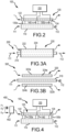
- FIGS. 3A and 3B show alternative variable mass balance bars in vibratory meters that do not, for clarity, depict meter electronics or pickoff sensors.
- FIG. 3A shows a first alternative vibratory meter 200 comprising a measuring conduit 210 disposed within and surrounded by a cylindrical variable mass balance bar 220.
- the cylindrical variable mass balance bar 220 is comprised of a cylindrical balance body 222 and a balance fluid 224 contained within the cylindrical balance body 222.
- the balance fluid 224 is shown as entering the cylindrical balance body 222 at an inlet proximate an inlet arrow, being conveyed by the cylindrical balance body 222, and provided by the cylindrical balance body 222 at an outlet proximate an outlet arrow.
- FIG. 3B shows a second alternative vibratory meter 300 comprising a measuring conduit 310 disposed within a dual variable mass balance bar 320.
- the dual variable mass balance bar 320 is comprised of a first half variable mass balance bar 320a and a second half variable mass balance bar 320b.
- the first half variable mass balance bar 320a is comprised of a first half balance body 322a and a first half balance fluid 324a.
- the second half variable mass balance bar 320b is comprised of a second half balance body 322b and a second half balance fluid 324b.
- the balance fluid is therefore comprised of the first and second half balance fluids 324a, 324b respectively contained within the first and second half balance bodies 322a, 322b.
- the first and second half balance fluids 324a, 324b are shown as respectively entering the first and second half balance bodies 322a, 322b at inlets proximate an inlet arrow, being conveyed by the first and second half balance bodies 322a, 322b, and provided by the first and second half balance bodies 322a, 322b at outlets proximate an outlet arrow.
- variable mass balance bars and the measuring conduits containing a process material may be balanced if their respective resonance frequencies are equal.
- the resonance frequencies may be equal if the relationship of below equation [3] is satisfied.
- the spring constants and mass of the measuring conduit and the balance body may be determined and established by a design of a vibratory meter, such as the vibratory meters 100, 200, 300 described above with reference to FIGS. 2-3B .
- a design of a vibratory meter such as the vibratory meters 100, 200, 300 described above with reference to FIGS. 2-3B .
- geometries, dimensions, and materials of the measuring conduit and the balance body may be chosen such that the spring constants have desired values.
- the measuring conduit and the balance body may have a cylindrical shape having lengths, inner diameter, outer diameter, and material selected to obtain desired masses and spring constants of the measuring conduit and the balance body.
- the spring constants and the masses of the measuring conduit and the balance body may be determined during a design of a vibratory meter. Additionally, the mass of the process material may sufficiently vary such that the vibratory meter is no longer balanced. That is, the vibratory meter may not conform to equation [3] due to variation in the mass of the process material. However, by varying the mass of the balance fluid, conformity to equation [3] may be achieved. For example, should a mass of the process material increase significantly due to an increase in a density of the process material, then correspondingly increasing a density of the balance fluid may ensure that the vibratory meter still complies with equation [3].
- the mass of the variable mass balance bar may be controlled by controlling properties of the balance fluid.
- the density of the balance fluid may be selected.
- the density of the balance fluid after being selected, may be controlled by, for example, controlling other properties of the balance fluid, such as a composition, temperature, or the like, of the balance fluid. Controlling the properties of the balance fluid may be manual, such as simply selecting an appropriate fluid having the selected density. However, the mass of the balance fluid may be controlled automatically.
- An exemplary system for automatically controlling the density of the balance fluid, and thereby controlling the mass of the variable mass balance bar, is described in the following with reference to FIG. 4 .
- the left pickoff sensor 130a, the right pickoff sensor 130b, and the driver 140 are disposed between and coupled to the measuring conduit 110 and the variable mass balance bar 120.
- the left pickoff sensor 130a, the right pickoff sensor 130b, and the driver 140 are shown as being communicatively coupled to a meter electronics 150.
- the meter electronics 150 may provide a drive signal to the driver 140 and receive sensor signals from the left pickoff sensor 130a and the right pickoff sensor 130b to measure properties of the material in the measuring conduit 110, such as density, mass flow rates, or the like.
- the mixer 402 is shown as being comprised of a plurality of inlets, each of which is fluidly coupled to a corresponding balance fluid component.
- the mixer 402 may also include valves, such as flow rate valves, that regulate flow rates of a corresponding balance fluid component.
- the mixer 402 may also select one of, or mix two or more of, the plurality of balance fluid components into the balance fluid 124.
- the mixer 402 may include a control circuit with a memory that stores the component densities ⁇ 1 , ⁇ 2 , ... ⁇ n of the plurality of balance fluid components.
- the control circuit may store and/or receive other values, such as a volume of the measuring conduit 110, a density of the process material in the measuring conduit 110, a volume of the balance body 120, or the like.
- the mixer could operate without a feedback from the meter electronics 150 if, for example, the density of the process material in the measuring conduit 110 is known along with the volume of the measuring conduit 110.
- the above equation may assume there is no reaction between any of the balance fluid components that would change the composition and density of the balance fluid 124.
- the mixer 402 may include a density meter that measures a density of the balance fluid components and/or the balance fluid 124 provided to the balance body 122.
- the measured densities may be used to adjust the density of the balance fluid 124 provided to the balance body 122.
- the control circuit in the mixer 402 may adjust (e.g., increase or decrease) a mass fraction x i of one or more of the balance fluid components so the measured density results in the balance fluid 124 meeting the requirements of equation [4].
- the mixer 402 may be used to provide the balance fluid 124 so that the variable mass balance bar 120 balances the measuring conduit 110 containing the process material without controlling a volume of the balance fluid 124.
- the system 400 may balance the measuring conduit 110 without controlling a flow rate of the balance fluid 124 provided to the balance body 122.
- other systems may control a volume of a balance fluid in a balance body.
- valves may be employed, such as those described below with reference to FIG. 5 .
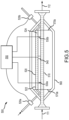
- FIG. 5 shows a vibratory meter 500 including a variable mass balance bar 520.
- the vibratory meter 500 includes a measuring conduit 510.
- the variable mass balance bar 520 is adjacent to a measuring conduit 510, which may be the same as or different than the measuring conduit 510 shown in FIG. 1 .
- ends of the measuring conduit 510 and the variable mass balance bar 520 may be coupled together with, for example, a first coupler 570a and a second coupler 570b.
- the first and second couplers 570a, 570b are also coupled to a case 560.
- variable mass balance bars for balancing measuring conduits with a straight tube configuration.
- the vibratory meter 500 included the inlet valve 520a and the outlet valve 520b.
- Other configurations may be employed that use alternative measuring conduit geometries and more or fewer balance fluid valves.
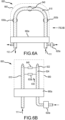
- An exemplary vibratory meter having an alternative configuration is described below with reference FIGS. 6A and 6B .
- FIGS. 6A and 6B show a vibratory meter 600 with a variable mass balance bar 620.
- the vibratory meter 600 includes a measuring conduit 610.
- the measuring conduit 610 is disposed adjacent to the variable mass balance bar 620.
- the variable mass balance bar 620 is comprised of a balance body 622 and a balance fluid 624.
- the vibratory meter 600 is shown as including pickoff sensors 630 that are disposed between, and coupled to, the measuring conduit 610 and the variable mass balance bar 620.
- the pickoff sensors 630 are comprised of a left pickoff sensor 630a and a right pickoff sensor 630b.
- the vibratory meter 600 also includes a driver 640 disposed between, and coupled to, the measuring conduit 610 and the variable mass balance bar 620.
- a mixer may be used to provide the balance fluid 524, 624 so that the variable mass balance bar 520, 620 balances the measuring conduit 510, 610 containing the process material without determining whether the measuring conduit 510, 610 is balanced.
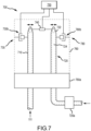
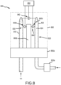
- vibratory meters or systems employing the vibratory meters may also determine if a balance fluid balances a measuring conduit containing the process material. Exemplary systems and vibratory meters are discussed below with reference to FIGS. 7 and 8 .
- the vibratory meter 700 also includes balance sensors 780 that are disposed between, and coupled to, the variable mass balance bar 720 and the case 760.
- the balance sensors 780 are comprised of a first balance sensor (not shown due to view) and a second balance sensor 780b.
- the vibratory meter 700 also includes a driver 740 disposed between, and coupled to, the measuring conduit 710 and the variable mass balance bar 720.
- the balance sensors 780 are mechanically coupled to the case 760.
- the first balance sensor is also mechanically coupled to the variable mass balance bar 720.
- the second balance sensor 780b is also mechanically coupled to the measuring conduit 710.
- the balance sensors 780 may be configured to measure a displacement of the variable mass balance bar 720 relative to the case 760.
- the balance sensors 780 are also configured to provide balance sensor signals to the meter electronics 750.
- the vibratory meters 700, 800 include the cases 760, 860.
- the cases 760, 860 are mechanically coupled to the bases 760a, 860a, which may be coupled to a reference structure, such as the plate 860b in FIG. 8 .
- the measuring conduits 710, 810 extend through the bases 760a, 860a into a space formed by the cases 760, 860.
- the cases 760, 860, bases 760a, 860a, and plate 860b may be substantially rigid structures.
- the bases 760a, 860a may therefore be coincident with vibration nodes of the measuring conduits 710, 810 and the variable mass balance bars 720, 820.
- the cases 760, 860 and the plate 860b may be reference structures or surfaces.
- surfaces on the cases 760, 860 and/or the plate 860b may be assumed to have zero displacement with respect to time when the measuring conduit 710, 810 and/or variable mass balance bar 720, 820 vibrate. Accordingly, a displacement of the measuring conduit 710, 810 and/or variable mass balance bar 720, 820 may be measured relative to the reference surface or reference structure, which may be the cases 760, 860 and/or plate 860b.
- the measuring conduit 710, 810 may be balanced when a resonance frequency of the measuring conduit 710, 810 containing the process material is equal to a resonance frequency of the variable mass balance bar 720, 820. Accordingly, by measuring the displacement of the measuring conduit 710, 810 containing the process material with the pickoff sensors 730, 830 and the displacement of the variable mass balance bar 720, 820 with the balance sensors 780, 880, one may calculate frequencies of the measuring conduit 710, 810 and the variable mass balance bar 720, 820. The frequencies may be determined by the meter electronics 750, 850 based on sensor signals provided by the pickoff sensors 730, 830 and the balance sensors 780, 880. When the frequency of the measuring conduits 710, 810 containing the process material are respectively equal to the frequencies of the variable mass balance bars 720, 820, then the measuring conduits 710, 810 are balanced by the variable mass balance bars 720, 820.
- At least one balance sensor 980 is comprised of a first balance sensor 980a and a second balance sensor 980b that are mechanically coupled to the case 160 and the variable mass balance bar 120.
- a single balance sensor may be employed in other systems or vibratory meters.
- the first balance sensor 980a and the second balance sensor 980b are communicatively coupled to the meter electronics 150.
- the first balance sensor 980a and the second balance sensor 980b are configured to measure a displacement of the variable mass balance bar 120 relative to the case 160.
- the first and second balance sensors 980a, 980b are also configured to provide balance sensor signals to the meter electronics 150.
- a displacement of the measuring conduit 110 and the variable mass balance bar 120 may be measured relative to a common reference structure or reference surface.
- the case 160 is assumed to not be vibrating or is vibrating without relative displacement of its surfaces and therefore any displacement of the measuring conduit 110 and the variable mass balance bar 120 may be measured and compared.
- the at least one balance sensor 980 may also be used to determine if the variable mass balance bar 120 balances the measuring conduit 110 containing the process material. For example, as discussed above, the variable mass balance bar 120 may balance the measuring conduit 110 containing the process material when the resonance frequency of the variable mass balance bar 120 is equal to a resonance frequency of the measuring conduit 110. The at least one balance sensor 980 may detect a displacement (e.g., distance, velocity, and/or acceleration) of the variable mass balance bar 120 and provide a balance bar displacement signal to the meter electronics 150. The meter electronics 150 may determine if the resonance frequency of the variable mass balance bar 120 is equal to the resonance frequency of the measuring conduit 110 containing the process material.
- a displacement e.g., distance, velocity, and/or acceleration
- one or more frequencies of the drive signal provided to the driver 140 may be varied such that a drive gain, or other variable corresponding to an amplitude of the drive signal, may be minimized.
- the one or more frequencies of the drive signal may include a component frequency of the drive signal.
- the drive signal may be comprised of one or more components having distinct sinusoidal frequencies.
- the drive signal may be comprised of a component at or tracking a resonance frequency of the measuring conduit 110 containing the process material and a component at or tracking a resonance frequency of the variable mass balance bar 120. Accordingly, an amplitude of the component corresponding to the resonance frequency of the variable mass balance bar 120 may be minimized.
- the component corresponding to the resonance frequency of the variable mass balance bar 120 may be tracked by minimizing the drive gain while varying the frequency of the component.
- the drive gain may be a measure of a drive signal power required to maintain an amplitude of the measuring conduit 110 containing the process material.
- the drive gain may be a ratio of a drive signal amplitude and one or more signal amplitudes of the signals provided by the at least one balance sensor 980 and/or the sensor signals provided by the left and right pickoff sensors 130a, 130b. That is, the drive gain may be determined for and correspond to the variable mass balance bar 120 and/or the measuring conduit 110 containing the process material.
- the density may be selected in any suitable manner, such as selecting a particular fluid, mixing fluid components, or the like.
- the fluid or fluid components may or may not be a process material.
- a non-process material may be advantageous because a temperature of the balance may be controlled, rather than determined by the process material being measured.
- the method 1000 may also include providing the balance fluid to at least one inlet configured to receive the balance fluid.
- Providing the balance fluid to the balance body may also include mixing a plurality of balance fluid components into the balance fluid and providing the balance fluid to the balance body. Accordingly, the variable mass balance bar may balance the measuring conduit containing the process material.
- a resonance frequency of the balance body containing the balance fluid may be equal to a resonance frequency of the measuring conduit containing the process material. Accordingly, the resonance frequency of the variable mass balance bar may be equal to the resonance frequency of the measuring conduit containing the process material.
- the frequencies may be equal to each other according to above equations [1] - [3].
- the mass of the balance body may be equal to a mass of the measuring conduit. Accordingly, the stiffness of the balance body may be the same as the stiffness of the measuring conduit. Alternatively, the mass of the balance body may not be equal to the mass of the measuring conduit. Accordingly, the stiffness of the measuring conduit may not be equal to the stiffness of the measuring conduit. For example, if the mass of the balance body is less than the mass of the measuring conduit, then the stiffness of the balance body may be greater than the stiffness of the measuring conduit. However, the above depends on the mass of the process material, as above equation [3] illustrates.
- the method 1000 may further comprise other steps such as configuring the balance body to be mechanically coupled to the measuring conduit.
- couplers or case ends may be affixed to ends of the balance body and ends of the measuring conduit.
- any suitable mechanical coupling may be employed.
- at least one balance sensor may be coupled to the variable mass balance bar and a reference structure of a vibratory meter.
- the balance sensor may be used to determine if the variable mass balance bar balances the measuring conduit.
- the balance sensor may be used to determine if a resonance frequency of the measuring conduit is equal a resonance frequency of the variable mass balance bar, as is described above.
- an accelerometer may be coupled to the reference structure to, for example, sense a vibration of the reference structure with the accelerometer.
- the accelerometer and/or balance sensor may be used to determine if the reference structure is vibrating due to the variable mass balance bar not balancing the measuring conduit containing the process material.
- Balancing the vibratory meter may include monitoring one or more variables.
- the drive gain signal provided to the driver 140 and the acceleration signal from the accelerometer 990 may be monitored while the mixer 902 varies a density of the balance fluid 124 provided to the balance body 122. If the frequency of the component of the drive signal corresponding to the variable mass balance bar 120 and the frequency of the component of the drive signal corresponding to the measuring conduit 110 containing the process material are substantially equal and the acceleration signal from the accelerometer 990 is minimized, then the meter electronics 150 may determine that the vibratory meter 100' is balanced.
- each variable may have a corresponding threshold. These thresholds may also be correlated depending on process conditions. For example, the frequencies of the components of the drive signal may be within a threshold of each other and the amplitude of the acceleration may be less than a threshold before the meter electronics 150 may determine that the vibratory meter 100' is balanced. The determination that the vibratory meter 100' is balanced may be used in various ways, such as terminating the method 1000, an indication that measured mass flow rate may be accurate, or the like. The variables may also be quantified to provide a measuring of the accuracy of the measured mass flow rate, etc.
- the above describes the vibratory meters 100-300, 500-800 that include variable mass balance bars 120-320, 520-820, as well as systems 400, 900 having vibratory meters 100, 100' that include variable mass balance bars 120, that can be used to balance the measuring conduits 110-310, 510-810.
- the vibratory meters 100-300, 500-800 may accurately measure a property of the process material.
Landscapes
- Physics & Mathematics (AREA)
- Fluid Mechanics (AREA)
- General Physics & Mathematics (AREA)
- Engineering & Computer Science (AREA)
- Signal Processing (AREA)
- Measuring Volume Flow (AREA)
Claims (15)
- Ein vibratorisches Messgerät (100-300, 500-800) mit einem variablen Massenausgleichsstab (120-320, 520-820), wobei das vibratorische Messgerät (100-300, 500-800) Folgendes umfasst:eine Messröhre (110-310, 510-810);den variablen Massenausgleichsstab (120-320, 520-820), der mit der Messröhre (110-310, 510-810) mechanisch gekoppelt ist, dadurch gekennzeichnet, dass eine Masse eines Ausgleichsfluids des variablen Massenausgleichsstabs (120-320, 520-820) basierend auf einem Fluideigenschaftswert eines Prozessmaterials ausgewählt wird, das durch die Messröhre (110-310) umschlossen ist, um während einer Messung die Messröhre (110-310, 510-810), die das Prozessmaterial umschließt, auszugleichen;eine Messgerätelektronik (150, 550, 750, 850), die mit der Messröhre (110, 510, 710, 810) kommunikativ gekoppelt ist, wobei die Messgerätelektronik (150, 550, 750, 850) zu mindestens einem von Folgendem konfiguriert ist: Bestimmen, ob der variable Massenausgleichsstab (120-320, 520, 720, 820) die Messröhre (110-310, 510, 710, 810), die das Prozessmaterial umschließt, ausgleicht, und Auswählen der Masse des Ausgleichsfluids des variablen Massenausgleichsstabs (120-320, 520, 720, 820).
- Vibratorisches Messgerät (100-300, 500-800) nach Anspruch 1, wobei eine Resonanzfrequenz des variablen Massenausgleichsstabs (120-320, 520-820) gleich einer Resonanzfrequenz der Messröhre (110-310, 510-810), die das Prozessmaterial umschließt, ist.
- Vibratorisches Messgerät (100-300, 500-800) nach einem von Anspruch 1 oder Anspruch 2, wobei:die Masse des variablen Massenausgleichsstabs (120-320, 520-820) eines von Folgendem ist: gleich oder nicht gleich einer Masse der Messröhre (110-310, 510-810), die das Prozessmaterial umschließt; undeine Steifigkeit des variablen Massenausgleichsstabs (120-320, 520-820) eines von Folgendem ist: gleich oder nicht gleich einer Steifigkeit der Messröhre (110-310, 510-810) .
- Vibratorisches Messgerät (100-300, 500-800) nach einem der vorhergehenden Ansprüche 1 bis 3, wobei der variable Massenausgleichsstab (120-320, 520-820) mindestens einen Einlass und mindestens einen Auslass beinhaltet, wobei die Masse des variablen Massenausgleichsstabs (120-320, 520-820) zwischen dem Einlass und dem Auslass liegt.
- Vibratorisches Messgerät (700, 800) nach einem der vorhergehenden Ansprüche 1 bis 4, das ferner mindestens einen Ausgleichssensor (780, 880) umfasst, der mit dem variablen Massenausgleichsstab (720, 820) und einer Bezugsstruktur (760, 860b) des vibratorischen Messgeräts (700, 800) mechanisch gekoppelt ist und mit der Messgerätelektronik (750, 850) kommunikativ gekoppelt ist, wobei die Messgerätelektronik (750, 850) dazu konfiguriert ist, zu bestimmen, ob der variable Massenausgleichsstab (720, 820) die Messröhre (710, 810), die das Prozessmaterial umschließt, ausgleicht.
- Vibratorisches Messgerät (700, 800) nach einem der vorhergehenden Ansprüche 1 bis 5, wobei die Messgerätelektronik (750, 850), die dazu konfiguriert ist, zu bestimmen, ob der variable Massenausgleichsstab (720, 820) die Messröhre (710, 810), die das Prozessmaterial umschließt, ausgleicht, die Messgerätelektronik (750, 850) umfasst, die dazu konfiguriert ist, zu bestimmen, ob eine Resonanzfrequenz der Messröhre (710, 810), die das Prozessmaterial umschließt, gleich einer Resonanzfrequenz des variablen Massenausgleichsstabs (720, 820) ist.
- Ein System (400, 900), das Folgendes umfasst:ein vibratorisches Messgerät (100, 100') nach einem der vorhergehenden Ansprüche 1 bis 6;mindestens ein Durchflusssteuerungsventil (920a) und ein Mischgerät (402, 902), die mit der Messgerätelektronik (150) kommunikativ gekoppelt sind, wobei das Durchflusssteuerungsventil (820a, 920a) und das Mischgerät (920) dazu konfiguriert sind, die Masse des Ausgleichsfluids des variablen Massenausgleichsstabs zu steuern.
- System (900) nach Anspruch 7, wobei das vibratorische Messgerät (100') ferner eine Bezugsstruktur (160, 160a, 160b) umfasst, die mit dem variablen Massenausgleichsstab (120) gekoppelt ist, ferner mindestens einen Ausgleichssensor (980) umfasst, der mit dem variablen Massenausgleichsstab (120) und der Bezugsstruktur (160, 160a, 160b) mechanisch gekoppelt ist.
- System (900) nach einem von Anspruch 7 oder Anspruch 8, wobei die Messgerätelektronik (150) dazu konfiguriert ist, die Masse des Ausgleichsfluids (124) des variablen Massenausgleichsstabs (120) durch mindestens eines von Folgendem auszuwählen: Steuern einer Dichte des Ausgleichsfluids (124) und Steuern eines Volumens des Ausgleichsfluids (124) des variablen Massenausgleichsstabs (120) .
- System (900) nach einem von Anspruch 8 oder Anspruch 9, das ferner ein Beschleunigungsmessgerät (990) umfasst, das mit der Bezugsstruktur (160, 160a, 160b) gekoppelt und mit der Messgerätelektronik (150) kommunikativ gekoppelt ist, wobei das Beschleunigungsmessgerät (990) dazu konfiguriert ist, eine Vibration der Bezugsstruktur (160, 160a, 160b) zu erfassen.
- System (900) nach einem der vorhergehenden Ansprüche 8 bis 10, wobei die Messgerätelektronik (150), die dazu konfiguriert ist, zu bestimmen, ob der variable Massenausgleichsstab (120) die Messröhre (110) ausgleicht, die Messgerätelektronik (150) umfasst, die dazu konfiguriert ist, zu bestimmen, ob die Bezugsstruktur (160, 160a, 160b) des vibratorischen Messgeräts (100) aufgrund dessen, dass der variable Massenausgleichsstab (120) die Messröhre (110), die das Prozessmaterial umschließt, nicht ausgleicht, vibriert.
- Ein Verfahren zum Ausgleichen einer Messröhre mit einem variablen Massenausgleichsstab, dadurch gekennzeichnet, dass das Verfahren folgendes umfasst:Auswählen einer Masse eines Ausgleichsfluids basierend auf einem Fluideigenschaftswert eines Prozessmaterials, das durch die Messröhre umschlossen ist, um während einer Messung die Messröhre, die das Prozessmaterial umschließt, auszugleichen;Bereitstellen des Ausgleichsfluids für einen Ausgleichskörper; undBestimmen, ob der variable Massenausgleichsstab die Messröhre, die das Prozessmaterial umschließt, ausgleicht.
- Verfahren nach Anspruch 12, das ferner das Koppeln von mindestens einem Ausgleichssensor mit dem variablen Massenausgleichsstab und einer Bezugsstruktur eines vibratorischen Messgeräts und das Verwenden des Ausgleichssensors, um zu bestimmen, ob der variable Massenausgleichsstab die Messröhre, die das Prozessmaterial umschließt, ausgleicht, umfasst.
- Verfahren nach Anspruch 13, das ferner das Koppeln eines Beschleunigungsmessgeräts mit der Bezugsstruktur und das Erfassen einer Vibration der Bezugsstruktur mit dem Beschleunigungsmessgerät und das Bestimmen, ob die Bezugsstruktur aufgrund dessen, dass der variable Massenausgleichsstab die Messröhre, die das Prozessmaterial umschließt, nicht ausgleicht, vibriert, umfasst.
- Verfahren nach einem der vorhergehenden Ansprüche 12 bis 14, wobei das Bereitstellen des Ausgleichsfluids für den Ausgleichskörper das Mischen einer Vielzahl von Ausgleichsfluidkomponenten in das Ausgleichsfluid und das Bereitstellen des Ausgleichsfluids für den Ausgleichskörper umfasst.
Applications Claiming Priority (1)
| Application Number | Priority Date | Filing Date | Title |
|---|---|---|---|
| PCT/US2019/044055 WO2021021116A1 (en) | 2019-07-30 | 2019-07-30 | A variable mass balance bar |
Publications (2)
| Publication Number | Publication Date |
|---|---|
| EP4004497A1 EP4004497A1 (de) | 2022-06-01 |
| EP4004497B1 true EP4004497B1 (de) | 2024-07-03 |
Family
ID=67614649
Family Applications (1)
| Application Number | Title | Priority Date | Filing Date |
|---|---|---|---|
| EP19752802.9A Active EP4004497B1 (de) | 2019-07-30 | 2019-07-30 | Variabler massenausgleichsstab |
Country Status (5)
| Country | Link |
|---|---|
| US (1) | US11802786B2 (de) |
| EP (1) | EP4004497B1 (de) |
| JP (1) | JP7387869B2 (de) |
| CN (1) | CN114207387B (de) |
| WO (1) | WO2021021116A1 (de) |
Families Citing this family (1)
| Publication number | Priority date | Publication date | Assignee | Title |
|---|---|---|---|---|
| DE102023108372A1 (de) | 2023-03-31 | 2024-10-02 | Endress + Hauser Flowtec Ag | Coriolis-Durchflussmessgerät und Verfahren zum Kalibrieren und/oder Betreiben eines Coriolis-Durchflussmessgerätes |
Family Cites Families (14)
| Publication number | Priority date | Publication date | Assignee | Title |
|---|---|---|---|---|
| US4109524A (en) | 1975-06-30 | 1978-08-29 | S & F Associates | Method and apparatus for mass flow rate measurement |
| USRE31450E (en) | 1977-07-25 | 1983-11-29 | Micro Motion, Inc. | Method and structure for flow measurement |
| US4491025A (en) | 1982-11-03 | 1985-01-01 | Micro Motion, Inc. | Parallel path Coriolis mass flow rate meter |
| US5979246A (en) * | 1998-02-09 | 1999-11-09 | Micro Motion, Inc. | Spring rate balancing of the flow tube and a balance bar in a straight tube Coriolis flowmeter |
| US6354154B1 (en) * | 1999-06-30 | 2002-03-12 | Micro Motion, Inc. | Balance bar for a coriolis flowmeter |
| EP1221024A1 (de) * | 1999-10-14 | 2002-07-10 | Fmc Corporation | Dynamisches ausgleichssystem für coriolismassendurchflussmesser |
| US6634241B1 (en) * | 2000-09-22 | 2003-10-21 | Micro Motion, Inc. | Method and apparatus for bonding a connecting ring to a flow tube and balance bar of a coriolis flowmeter |
| DE10320973B4 (de) * | 2003-05-09 | 2006-04-27 | Siemens Ag | Bildgebendes Tomographie-Gerät und Verfahren zur Verminderung einer Unwucht an einem Tomographie-Gerät |
| BRPI0418911B1 (pt) * | 2004-07-01 | 2015-12-01 | Micro Motion Inc | pesos de equilíbrio divididos para eliminar o efeito de densidade em fluxo |
| CN101828097B (zh) | 2007-10-08 | 2012-08-15 | 微动公司 | 流量装置及其操作方法 |
| US8322230B2 (en) | 2008-05-01 | 2012-12-04 | Micro Motion, Inc. | Vibratory flow meter for determining one or more flow fluid characteristics of a multi-phase flow fluid |
| EP2435800A1 (de) * | 2009-05-26 | 2012-04-04 | Micro Motion, Inc. | Durchflussmesser mit ausgleichselement |
| CN103052868A (zh) | 2010-08-02 | 2013-04-17 | 西门子公司 | 科里奥利质量流量计和运行科里奥利质量流量计的方法 |
| JP5642249B2 (ja) * | 2013-10-30 | 2014-12-17 | マイクロ・モーション・インコーポレーテッドMicro MotionIncorporated | コリオリ流量計の力の釣合を取る方法及び装置 |
-
2019
- 2019-07-30 US US17/628,013 patent/US11802786B2/en active Active
- 2019-07-30 EP EP19752802.9A patent/EP4004497B1/de active Active
- 2019-07-30 WO PCT/US2019/044055 patent/WO2021021116A1/en not_active Ceased
- 2019-07-30 JP JP2022506014A patent/JP7387869B2/ja active Active
- 2019-07-30 CN CN201980099018.2A patent/CN114207387B/zh active Active
Also Published As
| Publication number | Publication date |
|---|---|
| CN114207387A (zh) | 2022-03-18 |
| JP7387869B2 (ja) | 2023-11-28 |
| WO2021021116A1 (en) | 2021-02-04 |
| US11802786B2 (en) | 2023-10-31 |
| US20220268613A1 (en) | 2022-08-25 |
| EP4004497A1 (de) | 2022-06-01 |
| JP2022542382A (ja) | 2022-10-03 |
| CN114207387B (zh) | 2025-09-12 |
Similar Documents
| Publication | Publication Date | Title |
|---|---|---|
| US9400203B2 (en) | Vibratory flow meter and zero check method | |
| KR101907426B1 (ko) | 코리올리 유량계 및 개선된 미터 제로를 갖는 방법 | |
| KR101868375B1 (ko) | 측방향 모드 강성을 결정함으로써 진동계에서 유체 튜브의 횡단면적의 변화에 대한 검출 | |
| US20120060626A1 (en) | Method for detecting plugging in a coriolis flow measuring device | |
| US9097570B2 (en) | Measuring transducer of a vibration-type having slits in the coupling elements for tuning eigenfrequency of the measuring tubes | |
| KR101018401B1 (ko) | 강성 계수 또는 질량 계수 중 하나 이상을 결정하기 위한방법 및 계측 전자장치 | |
| US20160332129A1 (en) | Radial mode fluid process meter | |
| EP3665446B1 (de) | Vorrichtung und verfahren zur beseitigung von falscher summierung bei einem durchflussmesser | |
| EP4004497B1 (de) | Variabler massenausgleichsstab | |
| HK40062314A (en) | A variable mass balance bar | |
| HK1213043B (en) | Improved detection of a change in the cross-sectional area of a fluid tube in a vibrating meter | |
| JP2017083465A (ja) | 改良されたメータゼロに関するコリオリ流量計および方法 | |
| HK1209180B (en) | Coriolis flowmeter and method with improved meter zero |
Legal Events
| Date | Code | Title | Description |
|---|---|---|---|
| STAA | Information on the status of an ep patent application or granted ep patent |
Free format text: STATUS: UNKNOWN |
|
| STAA | Information on the status of an ep patent application or granted ep patent |
Free format text: STATUS: THE INTERNATIONAL PUBLICATION HAS BEEN MADE |
|
| PUAI | Public reference made under article 153(3) epc to a published international application that has entered the european phase |
Free format text: ORIGINAL CODE: 0009012 |
|
| STAA | Information on the status of an ep patent application or granted ep patent |
Free format text: STATUS: REQUEST FOR EXAMINATION WAS MADE |
|
| 17P | Request for examination filed |
Effective date: 20220209 |
|
| AK | Designated contracting states |
Kind code of ref document: A1 Designated state(s): AL AT BE BG CH CY CZ DE DK EE ES FI FR GB GR HR HU IE IS IT LI LT LU LV MC MK MT NL NO PL PT RO RS SE SI SK SM TR |
|
| DAV | Request for validation of the european patent (deleted) | ||
| DAX | Request for extension of the european patent (deleted) | ||
| STAA | Information on the status of an ep patent application or granted ep patent |
Free format text: STATUS: EXAMINATION IS IN PROGRESS |
|
| P01 | Opt-out of the competence of the unified patent court (upc) registered |
Effective date: 20230526 |
|
| 17Q | First examination report despatched |
Effective date: 20230615 |
|
| GRAP | Despatch of communication of intention to grant a patent |
Free format text: ORIGINAL CODE: EPIDOSNIGR1 |
|
| STAA | Information on the status of an ep patent application or granted ep patent |
Free format text: STATUS: GRANT OF PATENT IS INTENDED |
|
| INTG | Intention to grant announced |
Effective date: 20240124 |
|
| GRAS | Grant fee paid |
Free format text: ORIGINAL CODE: EPIDOSNIGR3 |
|
| GRAA | (expected) grant |
Free format text: ORIGINAL CODE: 0009210 |
|
| STAA | Information on the status of an ep patent application or granted ep patent |
Free format text: STATUS: THE PATENT HAS BEEN GRANTED |
|
| AK | Designated contracting states |
Kind code of ref document: B1 Designated state(s): AL AT BE BG CH CY CZ DE DK EE ES FI FR GB GR HR HU IE IS IT LI LT LU LV MC MK MT NL NO PL PT RO RS SE SI SK SM TR |
|
| REG | Reference to a national code |
Ref country code: CH Ref legal event code: EP |
|
| REG | Reference to a national code |
Ref country code: DE Ref legal event code: R096 Ref document number: 602019054606 Country of ref document: DE |
|
| REG | Reference to a national code |
Ref country code: LT Ref legal event code: MG9D |
|
| REG | Reference to a national code |
Ref country code: NL Ref legal event code: MP Effective date: 20240703 |
|
| PG25 | Lapsed in a contracting state [announced via postgrant information from national office to epo] |
Ref country code: PT Free format text: LAPSE BECAUSE OF FAILURE TO SUBMIT A TRANSLATION OF THE DESCRIPTION OR TO PAY THE FEE WITHIN THE PRESCRIBED TIME-LIMIT Effective date: 20241104 |
|
| REG | Reference to a national code |
Ref country code: AT Ref legal event code: MK05 Ref document number: 1700245 Country of ref document: AT Kind code of ref document: T Effective date: 20240703 |
|
| PG25 | Lapsed in a contracting state [announced via postgrant information from national office to epo] |
Ref country code: NL Free format text: LAPSE BECAUSE OF FAILURE TO SUBMIT A TRANSLATION OF THE DESCRIPTION OR TO PAY THE FEE WITHIN THE PRESCRIBED TIME-LIMIT Effective date: 20240703 |
|
| PG25 | Lapsed in a contracting state [announced via postgrant information from national office to epo] |
Ref country code: PT Free format text: LAPSE BECAUSE OF FAILURE TO SUBMIT A TRANSLATION OF THE DESCRIPTION OR TO PAY THE FEE WITHIN THE PRESCRIBED TIME-LIMIT Effective date: 20241104 Ref country code: NL Free format text: LAPSE BECAUSE OF FAILURE TO SUBMIT A TRANSLATION OF THE DESCRIPTION OR TO PAY THE FEE WITHIN THE PRESCRIBED TIME-LIMIT Effective date: 20240703 |
|
| PG25 | Lapsed in a contracting state [announced via postgrant information from national office to epo] |
Ref country code: NO Free format text: LAPSE BECAUSE OF FAILURE TO SUBMIT A TRANSLATION OF THE DESCRIPTION OR TO PAY THE FEE WITHIN THE PRESCRIBED TIME-LIMIT Effective date: 20241003 |
|
| PG25 | Lapsed in a contracting state [announced via postgrant information from national office to epo] |
Ref country code: GR Free format text: LAPSE BECAUSE OF FAILURE TO SUBMIT A TRANSLATION OF THE DESCRIPTION OR TO PAY THE FEE WITHIN THE PRESCRIBED TIME-LIMIT Effective date: 20241004 Ref country code: FI Free format text: LAPSE BECAUSE OF FAILURE TO SUBMIT A TRANSLATION OF THE DESCRIPTION OR TO PAY THE FEE WITHIN THE PRESCRIBED TIME-LIMIT Effective date: 20240703 Ref country code: PL Free format text: LAPSE BECAUSE OF FAILURE TO SUBMIT A TRANSLATION OF THE DESCRIPTION OR TO PAY THE FEE WITHIN THE PRESCRIBED TIME-LIMIT Effective date: 20240703 |
|
| PG25 | Lapsed in a contracting state [announced via postgrant information from national office to epo] |
Ref country code: BG Free format text: LAPSE BECAUSE OF FAILURE TO SUBMIT A TRANSLATION OF THE DESCRIPTION OR TO PAY THE FEE WITHIN THE PRESCRIBED TIME-LIMIT Effective date: 20240703 |
|
| PG25 | Lapsed in a contracting state [announced via postgrant information from national office to epo] |
Ref country code: LV Free format text: LAPSE BECAUSE OF FAILURE TO SUBMIT A TRANSLATION OF THE DESCRIPTION OR TO PAY THE FEE WITHIN THE PRESCRIBED TIME-LIMIT Effective date: 20240703 |
|
| PG25 | Lapsed in a contracting state [announced via postgrant information from national office to epo] |
Ref country code: AT Free format text: LAPSE BECAUSE OF FAILURE TO SUBMIT A TRANSLATION OF THE DESCRIPTION OR TO PAY THE FEE WITHIN THE PRESCRIBED TIME-LIMIT Effective date: 20240703 Ref country code: IS Free format text: LAPSE BECAUSE OF FAILURE TO SUBMIT A TRANSLATION OF THE DESCRIPTION OR TO PAY THE FEE WITHIN THE PRESCRIBED TIME-LIMIT Effective date: 20241103 |
|
| PG25 | Lapsed in a contracting state [announced via postgrant information from national office to epo] |
Ref country code: CZ Free format text: LAPSE BECAUSE OF FAILURE TO SUBMIT A TRANSLATION OF THE DESCRIPTION OR TO PAY THE FEE WITHIN THE PRESCRIBED TIME-LIMIT Effective date: 20240703 Ref country code: HR Free format text: LAPSE BECAUSE OF FAILURE TO SUBMIT A TRANSLATION OF THE DESCRIPTION OR TO PAY THE FEE WITHIN THE PRESCRIBED TIME-LIMIT Effective date: 20240703 |
|
| PG25 | Lapsed in a contracting state [announced via postgrant information from national office to epo] |
Ref country code: RS Free format text: LAPSE BECAUSE OF FAILURE TO SUBMIT A TRANSLATION OF THE DESCRIPTION OR TO PAY THE FEE WITHIN THE PRESCRIBED TIME-LIMIT Effective date: 20241003 Ref country code: ES Free format text: LAPSE BECAUSE OF FAILURE TO SUBMIT A TRANSLATION OF THE DESCRIPTION OR TO PAY THE FEE WITHIN THE PRESCRIBED TIME-LIMIT Effective date: 20240703 |
|
| PG25 | Lapsed in a contracting state [announced via postgrant information from national office to epo] |
Ref country code: RS Free format text: LAPSE BECAUSE OF FAILURE TO SUBMIT A TRANSLATION OF THE DESCRIPTION OR TO PAY THE FEE WITHIN THE PRESCRIBED TIME-LIMIT Effective date: 20241003 Ref country code: PL Free format text: LAPSE BECAUSE OF FAILURE TO SUBMIT A TRANSLATION OF THE DESCRIPTION OR TO PAY THE FEE WITHIN THE PRESCRIBED TIME-LIMIT Effective date: 20240703 Ref country code: NO Free format text: LAPSE BECAUSE OF FAILURE TO SUBMIT A TRANSLATION OF THE DESCRIPTION OR TO PAY THE FEE WITHIN THE PRESCRIBED TIME-LIMIT Effective date: 20241003 Ref country code: LV Free format text: LAPSE BECAUSE OF FAILURE TO SUBMIT A TRANSLATION OF THE DESCRIPTION OR TO PAY THE FEE WITHIN THE PRESCRIBED TIME-LIMIT Effective date: 20240703 Ref country code: IS Free format text: LAPSE BECAUSE OF FAILURE TO SUBMIT A TRANSLATION OF THE DESCRIPTION OR TO PAY THE FEE WITHIN THE PRESCRIBED TIME-LIMIT Effective date: 20241103 Ref country code: HR Free format text: LAPSE BECAUSE OF FAILURE TO SUBMIT A TRANSLATION OF THE DESCRIPTION OR TO PAY THE FEE WITHIN THE PRESCRIBED TIME-LIMIT Effective date: 20240703 Ref country code: GR Free format text: LAPSE BECAUSE OF FAILURE TO SUBMIT A TRANSLATION OF THE DESCRIPTION OR TO PAY THE FEE WITHIN THE PRESCRIBED TIME-LIMIT Effective date: 20241004 Ref country code: FI Free format text: LAPSE BECAUSE OF FAILURE TO SUBMIT A TRANSLATION OF THE DESCRIPTION OR TO PAY THE FEE WITHIN THE PRESCRIBED TIME-LIMIT Effective date: 20240703 Ref country code: ES Free format text: LAPSE BECAUSE OF FAILURE TO SUBMIT A TRANSLATION OF THE DESCRIPTION OR TO PAY THE FEE WITHIN THE PRESCRIBED TIME-LIMIT Effective date: 20240703 Ref country code: CZ Free format text: LAPSE BECAUSE OF FAILURE TO SUBMIT A TRANSLATION OF THE DESCRIPTION OR TO PAY THE FEE WITHIN THE PRESCRIBED TIME-LIMIT Effective date: 20240703 Ref country code: BG Free format text: LAPSE BECAUSE OF FAILURE TO SUBMIT A TRANSLATION OF THE DESCRIPTION OR TO PAY THE FEE WITHIN THE PRESCRIBED TIME-LIMIT Effective date: 20240703 Ref country code: AT Free format text: LAPSE BECAUSE OF FAILURE TO SUBMIT A TRANSLATION OF THE DESCRIPTION OR TO PAY THE FEE WITHIN THE PRESCRIBED TIME-LIMIT Effective date: 20240703 |
|
| PG25 | Lapsed in a contracting state [announced via postgrant information from national office to epo] |
Ref country code: LU Free format text: LAPSE BECAUSE OF NON-PAYMENT OF DUE FEES Effective date: 20240730 |
|
| PG25 | Lapsed in a contracting state [announced via postgrant information from national office to epo] |
Ref country code: LU Free format text: LAPSE BECAUSE OF NON-PAYMENT OF DUE FEES Effective date: 20240730 |
|
| REG | Reference to a national code |
Ref country code: DE Ref legal event code: R097 Ref document number: 602019054606 Country of ref document: DE |
|
| PG25 | Lapsed in a contracting state [announced via postgrant information from national office to epo] |
Ref country code: RO Free format text: LAPSE BECAUSE OF FAILURE TO SUBMIT A TRANSLATION OF THE DESCRIPTION OR TO PAY THE FEE WITHIN THE PRESCRIBED TIME-LIMIT Effective date: 20240703 Ref country code: DK Free format text: LAPSE BECAUSE OF FAILURE TO SUBMIT A TRANSLATION OF THE DESCRIPTION OR TO PAY THE FEE WITHIN THE PRESCRIBED TIME-LIMIT Effective date: 20240703 Ref country code: SM Free format text: LAPSE BECAUSE OF FAILURE TO SUBMIT A TRANSLATION OF THE DESCRIPTION OR TO PAY THE FEE WITHIN THE PRESCRIBED TIME-LIMIT Effective date: 20240703 |
|
| PG25 | Lapsed in a contracting state [announced via postgrant information from national office to epo] |
Ref country code: EE Free format text: LAPSE BECAUSE OF FAILURE TO SUBMIT A TRANSLATION OF THE DESCRIPTION OR TO PAY THE FEE WITHIN THE PRESCRIBED TIME-LIMIT Effective date: 20240703 Ref country code: MC Free format text: LAPSE BECAUSE OF FAILURE TO SUBMIT A TRANSLATION OF THE DESCRIPTION OR TO PAY THE FEE WITHIN THE PRESCRIBED TIME-LIMIT Effective date: 20240703 Ref country code: BE Free format text: LAPSE BECAUSE OF NON-PAYMENT OF DUE FEES Effective date: 20240731 |
|
| PG25 | Lapsed in a contracting state [announced via postgrant information from national office to epo] |
Ref country code: SK Free format text: LAPSE BECAUSE OF FAILURE TO SUBMIT A TRANSLATION OF THE DESCRIPTION OR TO PAY THE FEE WITHIN THE PRESCRIBED TIME-LIMIT Effective date: 20240703 Ref country code: IT Free format text: LAPSE BECAUSE OF FAILURE TO SUBMIT A TRANSLATION OF THE DESCRIPTION OR TO PAY THE FEE WITHIN THE PRESCRIBED TIME-LIMIT Effective date: 20240703 |
|
| PLBE | No opposition filed within time limit |
Free format text: ORIGINAL CODE: 0009261 |
|
| STAA | Information on the status of an ep patent application or granted ep patent |
Free format text: STATUS: NO OPPOSITION FILED WITHIN TIME LIMIT |
|
| REG | Reference to a national code |
Ref country code: BE Ref legal event code: MM Effective date: 20240731 |
|
| 26N | No opposition filed |
Effective date: 20250404 |
|
| PGFP | Annual fee paid to national office [announced via postgrant information from national office to epo] |
Ref country code: GB Payment date: 20250619 Year of fee payment: 7 |
|
| PG25 | Lapsed in a contracting state [announced via postgrant information from national office to epo] |
Ref country code: FR Free format text: LAPSE BECAUSE OF NON-PAYMENT OF DUE FEES Effective date: 20240903 |
|
| PG25 | Lapsed in a contracting state [announced via postgrant information from national office to epo] |
Ref country code: IE Free format text: LAPSE BECAUSE OF NON-PAYMENT OF DUE FEES Effective date: 20240730 |
|
| PG25 | Lapsed in a contracting state [announced via postgrant information from national office to epo] |
Ref country code: SE Free format text: LAPSE BECAUSE OF FAILURE TO SUBMIT A TRANSLATION OF THE DESCRIPTION OR TO PAY THE FEE WITHIN THE PRESCRIBED TIME-LIMIT Effective date: 20240703 |
|
| PGFP | Annual fee paid to national office [announced via postgrant information from national office to epo] |
Ref country code: DE Payment date: 20250620 Year of fee payment: 7 |
|
| PGFP | Annual fee paid to national office [announced via postgrant information from national office to epo] |
Ref country code: CH Payment date: 20250801 Year of fee payment: 7 |
|
| PG25 | Lapsed in a contracting state [announced via postgrant information from national office to epo] |
Ref country code: CY Free format text: LAPSE BECAUSE OF FAILURE TO SUBMIT A TRANSLATION OF THE DESCRIPTION OR TO PAY THE FEE WITHIN THE PRESCRIBED TIME-LIMIT; INVALID AB INITIO Effective date: 20190730 |
|
| PG25 | Lapsed in a contracting state [announced via postgrant information from national office to epo] |
Ref country code: HU Free format text: LAPSE BECAUSE OF FAILURE TO SUBMIT A TRANSLATION OF THE DESCRIPTION OR TO PAY THE FEE WITHIN THE PRESCRIBED TIME-LIMIT; INVALID AB INITIO Effective date: 20190730 |