EP4004567B1 - Procédé et générateur pour la caractérisation d'un système oscillant - Google Patents
Procédé et générateur pour la caractérisation d'un système oscillant Download PDFInfo
- Publication number
- EP4004567B1 EP4004567B1 EP20743102.4A EP20743102A EP4004567B1 EP 4004567 B1 EP4004567 B1 EP 4004567B1 EP 20743102 A EP20743102 A EP 20743102A EP 4004567 B1 EP4004567 B1 EP 4004567B1
- Authority
- EP
- European Patent Office
- Prior art keywords
- voltage
- oscillating system
- time
- capacitance
- determining
- Prior art date
- Legal status (The legal status is an assumption and is not a legal conclusion. Google has not performed a legal analysis and makes no representation as to the accuracy of the status listed.)
- Active
Links
Images

Classifications
-
- G—PHYSICS
- G01—MEASURING; TESTING
- G01R—MEASURING ELECTRIC VARIABLES; MEASURING MAGNETIC VARIABLES
- G01R27/00—Arrangements for measuring resistance, reactance, impedance, or electric characteristics derived therefrom
- G01R27/02—Measuring real or complex resistance, reactance, impedance, or other two-pole characteristics derived therefrom, e.g. time constant
- G01R27/26—Measuring inductance or capacitance; Measuring quality factor, e.g. by using the resonance method; Measuring loss factor; Measuring dielectric constants ; Measuring impedance or related variables
- G01R27/2605—Measuring capacitance
-
- G—PHYSICS
- G01—MEASURING; TESTING
- G01R—MEASURING ELECTRIC VARIABLES; MEASURING MAGNETIC VARIABLES
- G01R29/00—Arrangements for measuring or indicating electric quantities not covered by groups G01R19/00 - G01R27/00
- G01R29/22—Measuring piezoelectric properties
-
- G—PHYSICS
- G01—MEASURING; TESTING
- G01R—MEASURING ELECTRIC VARIABLES; MEASURING MAGNETIC VARIABLES
- G01R31/00—Arrangements for testing electric properties; Arrangements for locating electric faults; Arrangements for electrical testing characterised by what is being tested not provided for elsewhere
- G01R31/28—Testing of electronic circuits, e.g. by signal tracer
- G01R31/282—Testing of electronic circuits specially adapted for particular applications not provided for elsewhere
- G01R31/2822—Testing of electronic circuits specially adapted for particular applications not provided for elsewhere of microwave or radiofrequency circuits
- G01R31/2824—Testing of electronic circuits specially adapted for particular applications not provided for elsewhere of microwave or radiofrequency circuits testing of oscillators or resonators
-
- B—PERFORMING OPERATIONS; TRANSPORTING
- B06—GENERATING OR TRANSMITTING MECHANICAL VIBRATIONS IN GENERAL
- B06B—METHODS OR APPARATUS FOR GENERATING OR TRANSMITTING MECHANICAL VIBRATIONS OF INFRASONIC, SONIC, OR ULTRASONIC FREQUENCY, e.g. FOR PERFORMING MECHANICAL WORK IN GENERAL
- B06B1/00—Methods or apparatus for generating mechanical vibrations of infrasonic, sonic, or ultrasonic frequency
- B06B1/02—Methods or apparatus for generating mechanical vibrations of infrasonic, sonic, or ultrasonic frequency making use of electrical energy
- B06B1/0207—Driving circuits
- B06B1/0223—Driving circuits for generating signals continuous in time
- B06B1/0238—Driving circuits for generating signals continuous in time of a single frequency, e.g. a sine-wave
- B06B1/0246—Driving circuits for generating signals continuous in time of a single frequency, e.g. a sine-wave with a feedback signal
- B06B1/0253—Driving circuits for generating signals continuous in time of a single frequency, e.g. a sine-wave with a feedback signal taken directly from the generator circuit
-
- B—PERFORMING OPERATIONS; TRANSPORTING
- B06—GENERATING OR TRANSMITTING MECHANICAL VIBRATIONS IN GENERAL
- B06B—METHODS OR APPARATUS FOR GENERATING OR TRANSMITTING MECHANICAL VIBRATIONS OF INFRASONIC, SONIC, OR ULTRASONIC FREQUENCY, e.g. FOR PERFORMING MECHANICAL WORK IN GENERAL
- B06B1/00—Methods or apparatus for generating mechanical vibrations of infrasonic, sonic, or ultrasonic frequency
- B06B1/02—Methods or apparatus for generating mechanical vibrations of infrasonic, sonic, or ultrasonic frequency making use of electrical energy
- B06B1/06—Methods or apparatus for generating mechanical vibrations of infrasonic, sonic, or ultrasonic frequency making use of electrical energy operating with piezoelectric effect or with electrostriction
-
- B—PERFORMING OPERATIONS; TRANSPORTING
- B06—GENERATING OR TRANSMITTING MECHANICAL VIBRATIONS IN GENERAL
- B06B—METHODS OR APPARATUS FOR GENERATING OR TRANSMITTING MECHANICAL VIBRATIONS OF INFRASONIC, SONIC, OR ULTRASONIC FREQUENCY, e.g. FOR PERFORMING MECHANICAL WORK IN GENERAL
- B06B1/00—Methods or apparatus for generating mechanical vibrations of infrasonic, sonic, or ultrasonic frequency
- B06B1/02—Methods or apparatus for generating mechanical vibrations of infrasonic, sonic, or ultrasonic frequency making use of electrical energy
- B06B1/06—Methods or apparatus for generating mechanical vibrations of infrasonic, sonic, or ultrasonic frequency making use of electrical energy operating with piezoelectric effect or with electrostriction
- B06B1/0644—Methods or apparatus for generating mechanical vibrations of infrasonic, sonic, or ultrasonic frequency making use of electrical energy operating with piezoelectric effect or with electrostriction using a single piezoelectric element
-
- H—ELECTRICITY
- H10—SEMICONDUCTOR DEVICES; ELECTRIC SOLID-STATE DEVICES NOT OTHERWISE PROVIDED FOR
- H10N—ELECTRIC SOLID-STATE DEVICES NOT OTHERWISE PROVIDED FOR
- H10N30/00—Piezoelectric or electrostrictive devices
- H10N30/80—Constructional details
- H10N30/802—Circuitry or processes for operating piezoelectric or electrostrictive devices not otherwise provided for, e.g. drive circuits
-
- B—PERFORMING OPERATIONS; TRANSPORTING
- B06—GENERATING OR TRANSMITTING MECHANICAL VIBRATIONS IN GENERAL
- B06B—METHODS OR APPARATUS FOR GENERATING OR TRANSMITTING MECHANICAL VIBRATIONS OF INFRASONIC, SONIC, OR ULTRASONIC FREQUENCY, e.g. FOR PERFORMING MECHANICAL WORK IN GENERAL
- B06B2201/00—Indexing scheme associated with B06B1/0207 for details covered by B06B1/0207 but not provided for in any of its subgroups
- B06B2201/70—Specific application
- B06B2201/72—Welding, joining, soldering
Definitions
- the present invention relates to a method for determining at least one physical parameter of an electromechanical oscillating system that has a piezoelectric element and at least one other element that is vibrationally coupled to the piezoelectric element, the piezoelectric element having an electrode and a counter-electrode.
- the present invention also relates to a method for operating an ultrasonic oscillating system, in which the above-mentioned method for determining at least one physical parameter of the ultrasonic oscillating system is used.
- the present invention also relates to a generator for providing an AC voltage and for carrying out the aforementioned methods.
- Oscillating systems with piezoelectric elements are used in numerous areas of industry and research. Examples include the use of piezoelectric elements in loudspeakers, piezomotors and ultrasonic oscillating systems such as ultrasonic welding devices.
- the advantages of the present invention arise in all areas in which piezoelectric elements are used as part of an oscillating system and control or regulation of the oscillation is desired. The features and advantages of the present invention are explained below with a focus on the example of ultrasonic oscillating systems, in particular on the basis of industrial ultrasonic welding devices.
- the process quality and reproducibility of the process result depend significantly on the temporal behavior of the amplitude of the mechanical oscillation used.
- it is particularly desirable that the amplitude of the vibration for the duration of the process or even for the entire Service life of the ultrasonic welding device varies as little as possible, so that the welds made with the ultrasonic welding device are formed homogeneously and have a reproducible quality.
- the absolute size of the vibration amplitude is also decisive for the quality of the weld seam. Once the appropriate vibration amplitude for an ultrasonic welding process has been found, it is preferably used again and again for comparable processes.
- the control of the vibration amplitude or the behavior of the vibration amplitude over time therefore contributes significantly to the control of the quality and reproducibility of a weld seam made with an ultrasonic welding device or of the corresponding product.
- the oscillation amplitude of the relevant oscillating system can be controlled via an alternating voltage applied to the actuator (piezoelectric actuator).
- the relationship between the alternating voltage U ( t ) used, which naturally varies over time t , and the amplitude X of the oscillating system is as follows:
- the amplitude of oscillation X is proportional to the charge Q of the piezo actuator: X ⁇ Q.
- the applied AC voltage U is the only controlled variable that can be set externally. Therefore, the oscillation amplitude X can in principle be set/regulated by appropriately adjusting the AC voltage U.
- the capacitance C SW of the oscillating system is assumed to be an unchanging constant.
- the electrical capacitance C SW is usually determined before an ultrasonic oscillating system is put into operation by an external measurement or on the basis of previously known capacitance values of the electrical and piezoelectric elements of the ultrasonic oscillating system, and the value determined in this way is used as a basis for future processes.
- the electrical capacitance C SW of an oscillating system usually results from the sum of the capacitances of the electrical and piezoelectric elements of an oscillating system.
- the electrical capacitance C SW is often made up of at least the capacitance of the piezoelectric element C P and the electrical capacitance of the cable C cable used, which connects the piezoelectric element to an AC voltage source.
- the capacity of an ultrasonic oscillating system can change over time. For example, if an old cable connecting the piezoelectric element to an AC voltage source is replaced with a new cable, this can have an impact on the capacity of the ultrasonic vibration system, since the capacity of the new cable can often differ from the capacity of the old cable. This is particularly likely if the cable length differs between the old and new cable.
- the capacitance of the electrical and piezoelectric elements of the oscillating system changes intrinsically. These changes can be permanent due to aging, wear and tear or temporary due to external environmental influences such as temperature fluctuations.
- the stored value for the electrical capacitance C SW of the vibration system is used to determine the required AC voltage without checking whether the stored value still corresponds to the actual value. It is therefore often the case that an ultrasonic oscillating device is operated with a specific alternating voltage in order to achieve a specific vibration amplitude, but this vibration amplitude does not occur.
- the AC voltage applied to the piezoelectric element is set in such a way that a desired oscillation amplitude is set, which is to be expected assuming the initially determined value for the capacitance C SW .
- the electrical capacitance of the electrical and/or piezoelectric elements of the ultrasonic oscillating system changes over the course of use of the ultrasonic welding device, then the oscillation amplitude also changes.
- the changed vibration amplitude is usually less suitable for the process in question than the initially set vibration amplitude. Therefore, there is usually also a reduction in the process quality, ie a reduction in the quality of the weld seams produced.
- this object is achieved by a method according to claim 1 .
- it is a method for determining at least one physical parameter of an electromagnetic oscillating system that has a piezoelectric element and at least one other element vibrationally coupled to the piezoelectric element , wherein the piezoelectric element has an electrode and a counter-electrode, with the following steps: (a) applying an electrical alternating voltage between the electrode and counter-electrode for the duration of an excitation interval in order to stimulate mechanical oscillation of the oscillating system or a subsystem, so that after the excitation interval has expired the oscillating system or the subsystem executes a free, non-excited oscillation; (b) after the excitation has ended and during the free, non-excited oscillation of the oscillating system or the subsystem: (i) measuring a time profile of a voltage U which is present between the electrode and the counter-electrode, or (ii) short-circuiting the electrode and counter-electrode with a line and measuring a time
- a physical parameter of the oscillating system includes in particular the capacitance of the oscillating system, the capacitance of a piezoelectric element, the resonant frequency of the oscillating system, the anti-resonant frequency of the oscillating system, the modal equivalent capacitance of the oscillating system, the modal inductance of the oscillating system, the resonant damping coefficient of the oscillating system, the anti-resonant damping coefficient of the oscillating system, the modal equivalent resistance of the oscillating system and other parameters characterizing the oscillation, we need to understand the resonance oscillation quality and the anti-resonance oscillation quality.
- an oscillating system can be excited as a whole or partially to a mechanical oscillation.
- the elements that are excited to oscillate mechanically form a subsystem of the oscillating system.
- the converter and the sonotrode can be connected to a generator via a vibration-damping cable, so that the generator is not set into mechanical vibration.
- the converter, the sonotrode and possibly parts of the cable form a subsystem of the vibration system, which as a whole also includes the entire cable and the generator.
- the excitation interval is preferably less than 100 milliseconds and more preferably less than 50 milliseconds.
- the method according to the invention allows physical parameters, including the capacitance C SW of the oscillating system, which characterize the oscillation, to be determined without it being necessary to disassemble the oscillating system and measure the individual elements of the oscillating system.
- the method also makes it possible to optimize the oscillating system depending on the specific parameters.
- the method according to the invention is a method for determining an electrical capacitance C SW of the oscillating system, wherein in step (b) the time profile of a voltage U applied between the electrode and the counter-electrode of the piezoelectric element is measured and in step (c) the electrical capacitance C SW is determined from the time course of the voltage U measured in step (b).
- This method makes it possible to determine the electrical capacitance C SW of an existing oscillating system much faster than would have been possible without the present invention.
- the method according to the embodiment discussed here requires only approximately 150 ms to 200 ms to be carried out completely, with the oscillating system not having to be dismantled or structurally modified.
- the capacitance of a piezoelectric element can be determined and also monitored extremely quickly and efficiently. Changes in the electrical capacitance C SW due to aging, wear or temperature fluctuations can be detected immediately and an appropriate response can be made within a very short time.
- an electrical capacitance C SW of the oscillating system is determined as follows:
- the time profile of a voltage measured in step (b) is divided into a direct voltage component U DC and an alternating voltage component U AC . Both parts appear superimposed.
- a high-pass filter is particularly preferably used in order to separate the direct voltage component U DC so that the time constant ⁇ can be precisely determined.
- the partial steps (aa), (bb) and (cc) can advantageously all be carried out automatically using appropriately designed algorithms, so that the capacitance C SW can be calculated by measuring the voltage U during free, non-excited oscillation of the oscillating system.
- the characteristic time interval ⁇ is also described as the half-life of the voltage signal.
- the method according to the invention makes use of the knowledge that the piezoelectric element and the other electrical elements of the oscillating system, viewed physically, behave similarly to a plate capacitor, which is initially charged and then discharges again.
- the capacitance of a plate capacitor can be determined from its discharge curve
- the capacitance of the oscillating system i.e. the piezoelectric and electrical elements of the oscillating system, can be determined from the time profile or drop in voltage U measured in step (b) (i). determine. In this case, only the direct voltage component U DC of the voltage U is relevant.
- the capacitance C p of a piezoelectric element used can be determined from the electrical capacitance C SW . If no capacitances of the oscillating system are connected in series, C p results from the subtraction of the capacitances of the remaining electrical or piezoelectric elements from C SW .
- step (a) a frequency 7 is excited that is close to or equal to a previously known resonant frequency of the oscillating system.
- step (b) occurs during a first measurement interval and step (d) occurs during a second measurement interval, the second measurement interval preferably occurring after the first measurement interval; (e) determining at least one further physical parameter, preferably an electrical substitute parameter of the oscillating system, from the time course of the current I measured in step (d).
- both the course of the voltage U and the course of the current I are measured, ie alternative (i) is carried out in step (b) and alternative (ii) in step (d).
- the voltage U is preferably first measured during a first measurement interval, after which the electrode is short-circuited with the counter-electrode and the current I is measured during a second measurement interval.
- the advantage of measuring the curves of voltage U and current 7 is that a complete set of parameters can be determined, which comprehensively characterizes the oscillation of the oscillating system. In this way, a picture of the actual state of an oscillating system with a piezoelectric element that is as complete as possible can be produced. This enables detailed process monitoring and efficient process control of the corresponding oscillating systems.
- the measured course of the current over time behaves in accordance with the mechanical vibration of the oscillating system.
- the resonant frequency or the anti-resonant frequency can therefore be determined in steps (f) or (g) by measuring a period of the oscillation of the current I or the voltage U or by a Fourier analysis of the time profile of the current or the voltage.
- the present invention also relates to a method for operating an ultrasonic oscillating system.
- the core of the method remains the method according to the invention described above for determining a physical parameter of an oscillating system.
- This method for determining a physical parameter is used in a method for operating an ultrasonic oscillating system, the ultrasonic oscillating system having at least one generator, one converter and one sonotrode, the sonotrode being brought into contact with a material to be processed in order to carry out ultrasonic processing, the Converter has at least one piezoelectric element, and wherein the generator provides an AC voltage which is converted into a mechanical vibration by the piezoelectric element of the converter.
- a method for determining at least one physical parameter is carried out according to one of the embodiments described above in relation to this method.
- processing pauses that occur for various reasons during process operation can be used to determine physical parameters that, for example, make a statement about the process quality of the ultrasonic oscillating system.
- This enables a very efficient integration of the method according to the invention for determining at least one physical parameter of an oscillating system in the process of ultrasonic oscillating systems.
- the following steps take place during the processing break: (A) Determining the electrical capacitance C SW of the ultrasonic oscillating system using a method for determining an electrical capacitance C SW of the ultrasonic oscillating system according to one of the embodiments described above (B) Adjusting the AC voltage as a function of the electrical capacitance C SW of the ultrasonic oscillating system determined in step (A).
- step (B) the method consequently goes beyond pure monitoring of oscillating systems.
- the reaction to the determination of the electrical capacitance C SW to be carried out in step (B) can in particular be called up automatically.
- the method can, for example, fall back on preset adjustment processes that run in step (B) as a function of the determined electrical capacitance C SW . If the electrical capacitance C SW is, for example, below or above a predefined lower or upper limit, the AC voltage applied can be switched off, for example, in order to reduce the risk of damage to the ultrasonic oscillating system.
- the embodiment discussed here provides temperature- and aging-adaptive control of the oscillation amplitude.
- a complete characterization of the oscillating system i.e. a determination of the electrical capacitance C SW , the resonance frequency f res , the anti-resonance frequency f antires , the modal equivalent capacitance C m , the modal equivalent inductance L m , the resonant damping coefficient D res , des anti-resonant damping coefficient D antires and the modal equivalent resistance R m of the oscillating system.
- This complete characterization takes place within a time interval of less than 300 ms, preferably less than 250 ms and particularly preferably less than 200 ms.
- step (B) has the following partial steps: (AA) determining the amplitude X of the mechanical oscillation of the ultrasonic oscillating system with the electrical capacitance C SW of the ultrasonic oscillating system determined in step (A); (BB) comparison of the amplitude X with a target amplitude X 0 ; (CC) Setting the frequency and/or the Amplitude of the AC voltage provided by the generator, so that an amplitude X equal to the target amplitude X 0 is set.
- This embodiment of the method according to the invention ensures that the mechanical oscillation amplitude of an ultrasonic oscillating system is kept as constant as possible over time in order to produce reproducible results with the oscillating system. This is achieved in an advantageous manner with the embodiment discussed here, since it is checked whether the mechanical vibration has the desired amplitude and as soon as a deviation is detected, this deviation is compensated for by a corresponding adjustment of the applied AC voltage, so that the desired value of the mechanical vibration amplitude reinstated. There are preferably repeated breaks in processing at regular intervals, during which steps (A) and (B) including sub-steps (AA), (BB) and (CC) take place.
- a device for providing an AC voltage and having means for carrying out a method according to one of the embodiments discussed above, the generator having an AC voltage source, a potential line between the AC voltage source and a potential connection and a ground line between the AC voltage source and a ground connection, wherein the ground line is connected to a ground.
- a short-circuit line connects the potential line to the ground line, the generator having a first switching device with which the potential line can be interrupted and a second switching device with which the short-circuit line can be interrupted.
- the generator according to the invention is specially designed for carrying out the methods discussed above.
- the first switching device is closed and the second switching device is open, so that the potential line is not interrupted and the short-circuit line is interrupted, so that an AC voltage is output at the potential connection.
- the first and the second switching device are open, so that no AC voltage is output at the potential connection and no short-circuit current can flow.
- the first switching device is opened and the second switching device is closed, so that a short-circuit current can flow through the short-circuit line.
- the generator according to the invention can be used universally, since it can easily be used for different oscillating systems in order to control the amplitude of the oscillation.
- the generator calibrates itself so that it provides exactly the AC voltage in each oscillating system that is required for the oscillating amplitude desired there, without the user having to manually store process-specific parameters.
- the generator and the means for measuring the voltage and the current are particularly preferably designed integrally as a generator with an integrated oscilloscope.
- the method according to the invention according to claims 1 to 6 can be carried out exclusively by using a generator, i.e. without using external measuring devices.
- the first and second switching devices are preferably designed as reed relays or semiconductor relays.
- Such relays advantageously ensure clean and quick switching, in particular quick disconnection of the potential line for carrying out steps (a) and (b) step (a) and clean short-circuiting in step (d) or the alternative (b) (ii) while the oscillating system performs free oscillation.
- the methods according to the invention and the generator according to the invention are preferably used for ultrasonic welding systems, particularly preferably for ultrasonic welding systems for welding plastics or nonwovens.
- the replacement diagram shown represents a case in which a piezoelectric element, namely a piezoelectric actuator 10, with the capacitance C p close to or equal to its resonant frequency, ie in a natural mode, is excited with an AC voltage U to oscillate.
- the equivalent circuit diagram consequently shows an oscillating system that has no further electrical or piezoelectric element apart from the piezoelectric actuator.
- equivalent diagram means that the behavior of the underlying piezoelectric ultrasonic oscillating system can be described with the behavior of the purely electrical circuit shown in the equivalent diagram, which represents an electrical oscillating circuit, which in reality also includes mechanical elements in addition to electrical elements.
- a voltage U is applied to the piezoelectric actuator 10 .
- the circuit of the piezo actuator 10 has, on the one hand, a parallel-connected capacitor with the capacitance C p , which represents the electrical domain of the equivalent diagram.
- the electrical domain is the area of the equivalent circuit diagram that represents the electrical properties of a piezoelectric element. In this sense, the piezoelectric element actually has the electrical properties of a capacitor.
- the current i Cm that flows in the electrical domain is consequently an electric current that actually flows in a piezoelectric element.
- the equivalent diagram also has a mechanical domain that includes an equivalent resistance R M , a capacitor with equivalent capacitance C M , and an inductor with equivalent inductance L M , these three elements being connected in series.
- the mechanical properties of a piezoelectric element are described with the mechanical domain of the equivalent diagram.
- the elements of the mechanical domain do not represent actual electrical components, but substitute elements. These replacement elements are designed in such a way that they form an electrical oscillating circuit in which the charge amplitude behaves exactly like the actual mechanical amplitude of the piezoelectric element. In this sense, the part of the current that flows in the mechanical domain and is therefore called "mechanical" current is not actually a current flowing in the piezoelectric element. It thus represents the conversion of electrical energy into mechanical energy within a piezoelectric element.
- the electrical component of the current I is in the figure 1 denoted by i Cp and the mechanical component of the current I is in the figure 1 marked i cm .
- the one shown is also measured total current I .
- the amplitude of the mechanical oscillation results from the mechanical component i m , so that the electrical component i Cp must be known in order to be able to determine i m , the charge Q and the amplitude X from a measurement of the total current I.
- the method according to the invention can be used in this case to determine this capacitance C p and thus improve the ability to determine and control the oscillation amplitude.
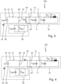
- FIG. 2 , 3 and 4 is shown in each case a circuit diagram of a generator having ultrasonic oscillating system 100, wherein the figures 2 , 3 and 4 each show different states of the circuit within the generator 20.
- the ultrasonic oscillating system 100 shown here also has a piezoelectric actuator 10, which as an equivalent circuit diagram according to figure 1 is shown.
- the piezoelectric actuator is vibrationally coupled to a further element of the oscillating system 100 (not shown here), for example a sonotrode, which is not shown here.
- the piezo actuator 10 is connected to the generator 20 according to the invention via a cable 15, the cable having a capacitance C cable .
- the generator 20 consists of an AC voltage source 23, which provides an AC voltage U.
- the voltage source 23 is connected via a ground line 26 to the ground connection 24' and a potential line 27 to the potential connection 24 of the generator.
- the potential line has a first switching device 21 with which the potential line can be interrupted, ie the electrically conductive function of the potential line can be switched off.
- a short-circuit line 28 is provided, which connects the potential line 27 and the ground line 26, this line also having a switching device 22 with which the short-circuit line 28 can be interrupted, ie the electrically conductive function of the short circuit -Line can be turned off.
- the signal input 11 is connected to the electrode and the counter-electrode of the piezoelectric actuator 10 in such a way that an alternating voltage applied to the signal input 11 is present between the electrode and the counter-electrode of the piezoelectric actuator. Since the signal input is connected to the generator via a cable, the electrode and the counter-electrode of the piezo actuator can be short-circuited via the switching device 22 by connecting the potential line and the ground line.
- the generator 20 also has a measuring device 30 in the form of an oscilloscope, which is connected by a parallel circuit to the potential connection 24 and the ground connection 24'. As shown in the circuit diagram, the measuring device 30 has an internal capacitance C probe and an internal resistance R probe .
- figure 2 accordingly shows the state of the circuit within an excitation interval [t 0 , t 1 ] according to step (a) of the method according to the invention.
- the switching device 21 is actuated in such a way that the connection between the voltage source and potential connection 24 - the potential line 27 - is interrupted, so that the ultrasonic oscillating system 10 has a free, non-applied oscillation because there is no longer any AC voltage between the electrode and counter-electrode of the piezo actuator.
- the corresponding state of the circuit with a now open switching device 21 is in figure 3 for the alternative (b) (i) and in figure 4 for the alternative (b)(ii).
- step (b) the generator remains for a first measurement interval [t 1 ,t 2 ], in which the voltage is measured with the measuring device 30 according to alternative (b) (i), in which in figure 3 shown state with the open switching devices 21 and 22.
- step (d) In order to measure the current or short-circuit current in accordance with step (d) in a second measurement interval [t 2 , t 3 ], the electrode and the counter-electrode are short-circuited by, as in figure 4 shown, the switching device 22 is actuated in such a way that it establishes a connection 28 between the potential line 27 and the ground line 26 .
- the short-circuit current is measured while the generator 20 according to the invention is in the figure 4 shown state is, after which the switching device 21 is open and the switching device 22 is closed, and thus there is an electrically conductive, direct connection between electrode and counter-electrode.
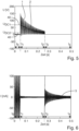
- the figure 5 shows in a two-dimensional diagram the time profile 1 of the voltage U and the time profile 2 of the direct current component of the voltage U in the excitation interval [t 0 ,t 1 ], in the first measurement interval [t 1 ,t 2 ] and in the second measurement interval [t 2 , t3 ].
- an ultrasonic oscillating system was excited in the time interval [t 0 ,t 1 ] with a frequency close to the resonant frequency of the ultrasonic oscillating system - by applying an alternating current (see the state of the circuit from figure 2 ).
- the applied alternating current was switched off, whereupon the ultrasonic oscillating system began to decay (see state of the circuit from figure 3 ).
- the figure 6 shows the time course of the current I for the same measurement for which the course of the voltage U in figure 2 is shown. So corresponds to the time t 3 from the figure 5 the time t 2 from the figure 2 , to which the electrode and counter-electrode are short-circuited.
- a short - circuit current triggered by the short-circuit is measured between the electrode and counter-electrode.
- the current has a course that alternates around the zero position, which means that it is a pure alternating current course.
- the amplitude of the alternating current falls exponentially. This can be seen from an imaginary envelope of the course of the alternating current.
Landscapes
- Engineering & Computer Science (AREA)
- Physics & Mathematics (AREA)
- General Physics & Mathematics (AREA)
- Mechanical Engineering (AREA)
- General Engineering & Computer Science (AREA)
- Apparatuses For Generation Of Mechanical Vibrations (AREA)
- Measurement Of Resistance Or Impedance (AREA)
- Investigating Or Analyzing Materials By The Use Of Ultrasonic Waves (AREA)
- General Electrical Machinery Utilizing Piezoelectricity, Electrostriction Or Magnetostriction (AREA)
Claims (12)
- Procédé pour déterminer une capacité électrique CSW d'un système oscillant électromécanique (100) qui comprend un élément piézoélectrique (10) et au moins un autre élément attaché par oscillations à l'élément piézoélectrique (10), dans lequel l'élément piézoélectrique (10) comprend une électrode et une contre-électrode, avec les étapes suivantes :a) appliquer une tension alternative entre l'électrode et la contre-électrode pendant la durée d'un intervalle d'excitation afin d'exciter une oscillation mécanique du système oscillant ou d'un système partiel du système oscillant si bien que, après la fin de l'intervalle d'excitation, le système oscillant ou le système partiel effectue une oscillation libre non-excitée,b) après la fin de l'excitation et pendant l'oscillation libre non-excitée du système oscillant ou du système partiel :
mesurer une évolution dans le temps d'une tension U (1) qui est appliquée entre l'électrode et la contre-électrode, etc) déterminer la capacité électrique Csw à partir de l'évolution dans le temps de la tension U (1) mesurée à l'étape b),dans lequel, à l'étape b), un dispositif de mesure (30) avec une capacité interne Cprobe et une résistance interne Rprobe sont utilisées pour mesurer l'évolution dans le temps de la tension U (1),et dans lequel l'étape c) comprend les étapes partielles :aa) déterminer une évolution dans le temps d'une composante de tension continue UDC (2) à partir de l'évolution dans le temps de la tension U (1) mesurée à l'étape b),bb) déterminer un intervalle de temps caractéristique τ pendant lequel une valeur initiale de la composante de tension continue U DC.0 , mesurée à l'étape b), a baissée à la valeur UDC.0le,cc) calculer la capacité électrique CSW avec l'intervalle de temps caractéristique τ. - Procédé selon la revendication 1, caractérisé en ce que, à l'étape cc), la capacité électrique CSW est calculée à l'aide de la formule CSW = (τ / RProbe) - CProbe .
- Procédé selon l'une des revendications précédentes, caractérisé en ce que, à l'étape a), une excitation est mise en oeuvre à une fréquence f proche de ou égale à une fréquence de résonance préalablement connue du système oscillant (100).
- Procédé selon l'une des revendications précédentes, caractérisé en ce que l'étape suivante supplémentaire est prévue :d) court-circuiter l'électrode et la contre-électrode à l'aide d'un conducteur (28) et mesurer une évolution dans le temps d'un courant I (3) passant par le conducteur, dans lequel l'étape b) est mise en oeuvre pendant un premier intervalle de mesure et l'étape d) est mise en oeuvre pendant un deuxième intervalle de mesure, dans lequel le deuxième intervalle de mesure est effectué de préférence après le premier intervalle de mesure,e) déterminer au moins une autre valeur caractéristique physique, de préférence un paramètre de remplacement électrique du système oscillant (100), à partir de l'évolution dans le temps du courant I (3) mesurée à l'étape d).
- Procédé selon la revendication 4, caractérisé en ce qu'une ou plusieurs des étapes suivantes sont prévues isolément ou en combinaison les unes avec les autres :f) déterminer une fréquence de résonance fres du système oscillant (100) à partir de l'évolution dans le temps du courant I (3) déterminée à l'étape d),g) déterminer une fréquence antirésonance fantires du système oscillant (100) à partir de l'évolution dans le temps de la tension U (1) déterminée à l'étape b),h) l'étape f), l'étape g) et le calcul de la capacité de remplacement modale Cm du système oscillant (100) à partir de la capacité CSW, à l'aide de la formule Cm = CSW ((fantires 2 / fres 2) - 1),i) l'étape h) et le calcul de l'inductance de remplacement modale Lm du système oscillant (100) à partir de la capacité de remplacement modale Cm , de préférence à l'aide de la formule Lm = 1 / (4π2fres 2Cm),j) déterminer un coefficient d'atténuation à résonance Dres qui caractérise une décroissance en fonction du temps t d'une enveloppe de l'évolution dans le temps du curant I (3),k) déterminer un coefficient d'atténuation à anti-résonance Dantires qui caractérise une décroissance en fonction du temps t d'une enveloppe de l'évolution dans le temps de la tension U (1),l) l'étape f), l'étape i), l'étape j) et le calcul de la résistance de remplacement modale Rm à l'aide de la formule Rm = 4 π Dres Lm fres.
- Procédé selon la revendication 5, caractérisé en ce qu'une caractérisation complète du système oscillant (100) est effectuée par la mise en oeuvre des étapes f) à j), de préférence dans un intervalle de temps de moins de 300 ms, de manière préférée dans un intervalle de temps de moins de 250 ms, et de manière particulièrement préférée dans un intervalle de temps de moins de 200 ms.
- Procédé pour faire fonctionner un système oscillant à ultra-sons (100),dans lequel le système oscillant à ultra-sons (100) comprend au moins un générateur (20), un convertisseur et une sonotrode, dans lequel, pour effectuer un traitement par ultrasons, la sonotrode est mise en contact avec un matériau à traiter,dans lequel le convertisseur comprend au moins un élément piézoélectrique (10)et dans lequel le générateur (20) met à disposition une tension alternative qui est transformé, par l'élément piézoélectrique (10) du convertisseur, en une oscillation mécanique,caractérisé en ce que,pendant une pause de traitement pendant laquelle la sonotrode n'est pas en contact avec le matériau à traiter, un procédé selon l'une des revendications 1 à 6 est mis en oeuvre.
- Procédé selon la revendication 7, caractérisé en ce que, pour la mise en oeuvre du procédé selon l'une des revendications 1 à 6, uniquement le générateur (20) est utilisé.
- Procédé selon la revendication 7 ou 8, caractérisé en ce que, pendant la pause de traitement, les étapes suivantes se déroulent :A) déterminer la capacité électrique CSW du système oscillant à ultrasons (100) à l'aide d'un procédé selon l'une des revendications 1 à 6,B) ajuster la tension alternative en fonction de la capacité électrique Csw du système oscillant à ultrasons (100) déterminée à l'étape A).
- Procédé selon la revendication 9, caractérisé en ce que l'étape B) comprend les étapes partielles suivantes :AA) déterminer l'amplitude X de l'oscillation mécanique du système oscillant à ultrasons (100) à l'aide de la capacité électrique CSW du système oscillant à ultrasons (100) déterminée à l'étape A),BB) comparer l'amplitude X à une amplitude X0 à atteindre,CC) ajuster la fréquence et/ou l'amplitude de la tension alternative mise à disposition par le générateur (20), si bien qu'une amplitude X égale à l'amplitude X0 à atteindre soit obtenue.
- Générateur (20) pour mettre à disposition une tension alternative et avec des moyens pour mettre en oeuvre un procédé selon l'une des revendications 1 à 10,avec une source de tension alternative (23), un conducteur de potentiel (27) entre la source de tension alternative et une borne de potentiel (24), un conducteur de masse (26) entre la source de tension alternative (23) et une borne de masse (24'), dans lequel le conducteur de masse (26) est relié à une terre,dans lequel un conducteur de court-circuit (28) relie le conducteur de potentiel (27) au conducteur de masse (26),dans lequel le générateur (20) comprend un premier dispositif de commutation (21) à l'aide duquel le conducteur de potentiel (27) peut être interrompu,et comprend un deuxième dispositif de commutation (22) à l'aide duquel le conducteur de court-circuit (28) peut être interrompu.
- Générateur selon la revendication 11, caractérisé en ce que le premier dispositif de commutation (21) et le deuxième dispositif de commutation (28) sont des relais reed ou des relais à semi-conducteur.
Applications Claiming Priority (2)
| Application Number | Priority Date | Filing Date | Title |
|---|---|---|---|
| DE102019119911.5A DE102019119911A1 (de) | 2019-07-23 | 2019-07-23 | Verfahren und Generator zur Charakterisierung eines Schwingsystems |
| PCT/EP2020/069972 WO2021013649A1 (fr) | 2019-07-23 | 2020-07-15 | Procédé et générateur pour la caractérisation d'un système oscillant |
Publications (2)
| Publication Number | Publication Date |
|---|---|
| EP4004567A1 EP4004567A1 (fr) | 2022-06-01 |
| EP4004567B1 true EP4004567B1 (fr) | 2023-08-16 |
Family
ID=71728722
Family Applications (1)
| Application Number | Title | Priority Date | Filing Date |
|---|---|---|---|
| EP20743102.4A Active EP4004567B1 (fr) | 2019-07-23 | 2020-07-15 | Procédé et générateur pour la caractérisation d'un système oscillant |
Country Status (8)
| Country | Link |
|---|---|
| US (1) | US12072363B2 (fr) |
| EP (1) | EP4004567B1 (fr) |
| JP (1) | JP7478809B2 (fr) |
| KR (1) | KR102917027B1 (fr) |
| CN (1) | CN114127568B (fr) |
| DE (1) | DE102019119911A1 (fr) |
| MX (1) | MX2022000828A (fr) |
| WO (1) | WO2021013649A1 (fr) |
Families Citing this family (2)
| Publication number | Priority date | Publication date | Assignee | Title |
|---|---|---|---|---|
| JP2024540338A (ja) * | 2021-11-19 | 2024-10-31 | テトラ ラバル ホールディングス アンド ファイナンス エス エイ | 包装機用密封装置、密封装置を有する包装機及び密封装置の動作方法 |
| CN119343113B (zh) * | 2022-06-08 | 2026-01-02 | 卡尔蔡司医疗技术股份公司 | 颗粒接触检测方法、眼科手术系统的控制台及眼科手术系统 |
Family Cites Families (26)
| Publication number | Priority date | Publication date | Assignee | Title |
|---|---|---|---|---|
| GB637112A (en) * | 1944-11-23 | 1950-05-10 | Radioelectriques Lab | Device for measuring the time constants of oscillating systems |
| JPS5024065B1 (fr) * | 1970-10-12 | 1975-08-13 | ||
| JPS4858823A (fr) * | 1971-11-19 | 1973-08-17 | ||
| SE504199C2 (sv) | 1995-05-04 | 1996-12-02 | Bengt Kasemo | Anordning vid mätning av resonansfrekvens och/eller dissipationsfaktor hos en piezoelektrisk kristallmikrovåg |
| IT1299401B1 (it) | 1998-03-27 | 2000-03-16 | Optikon 2000 Spa | Procedimento di ottimizzazione del pilotaggio di un attuatore piezoelettrico, in particolare per dispositivi facoemulsificatori, |
| JP3286606B2 (ja) * | 1998-09-03 | 2002-05-27 | 住友ベークライト株式会社 | 超音波振動子の駆動装置 |
| DE10160228A1 (de) * | 2001-12-07 | 2003-06-18 | Hesse & Knipps Gmbh | Kreuztransducer |
| DE10328113B4 (de) * | 2002-12-13 | 2006-07-20 | Endress + Hauser Gmbh + Co. Kg | Vorrichtung zum Betreiben einer schwingfähigen Einheit eines Vibrationsresonators |
| DE10325446B3 (de) | 2003-06-05 | 2005-03-03 | Robert Bosch Gmbh | Verfahren zum Detektieren eines Fehlers bei einem Piezoaktor und Ansteuerschaltung für einen Piezoaktor, sowie Piezoaktorsystem |
| DE102007021337A1 (de) * | 2007-05-07 | 2008-11-13 | Robert Bosch Gmbh | Piezoelektrische Antriebsvorrichtung |
| DE102007031168B3 (de) * | 2007-07-04 | 2009-01-02 | Sirona Dental Systems Gmbh | Verfahren zum Betrieb einer dentalen Ultraschallvorrichtung sowie dentale Ultraschallvorrichtung |
| TWI379087B (en) | 2008-12-30 | 2012-12-11 | Princeton Technology Corp | Method for measuring transconductance parameter |
| DE102010030791A1 (de) | 2010-07-01 | 2012-01-05 | Endress + Hauser Gmbh + Co. Kg | Vorrichtung zur Bestimmung und/oder Überwachung einer Prozessgröße eines Mediums |
| DE102010036257A1 (de) | 2010-09-03 | 2012-03-08 | Epcos Ag | Verfahren zur Kontrolle von Biegeschwingungen eines Piezoaktuators |
| US8564301B2 (en) * | 2010-11-08 | 2013-10-22 | Semiconductor Components Industries, Llc | Device and method for determining capacitance as a function of voltage |
| US8686798B2 (en) | 2011-05-19 | 2014-04-01 | Freescale Semiconductor, Inc. | Method and system for testing oscillator circuit |
| DE102011052283A1 (de) | 2011-07-29 | 2013-01-31 | Herrmann Ultraschalltechnik Gmbh & Co. Kg | Verfahren zur Berechnung der Schwingungsamplitude einer Sonotrode |
| WO2014074290A1 (fr) * | 2012-11-06 | 2014-05-15 | Newport Corporation | Système de détection de présence et de type de charges capacitives |
| US9136460B2 (en) * | 2014-01-29 | 2015-09-15 | Canon Kabushiki Kaisha | Piezoelectric element, method for manufacturing piezoelectric element, and electronic apparatus |
| DE102014111168A1 (de) * | 2014-08-06 | 2016-02-25 | Afag Holding Ag | Schwingförderer zur zweidimensionalen Bewegung von Objekten sowie Verfahren zum Betrieb des Schwingförderers |
| DE102014111166B4 (de) * | 2014-08-06 | 2017-10-19 | Afag Holding Ag | Schwingförderer und Verfahren zum Betrieb eines Schwingförderers |
| JP6439800B2 (ja) * | 2014-08-29 | 2018-12-19 | 株式会社村田製作所 | 発振回路及び発振回路の駆動方法 |
| DE102014012917B3 (de) * | 2014-09-05 | 2015-12-31 | Carl Zeiss Meditec Ag | Ophthalmochirurgisches System für die Phakoemulsifikation |
| DE102016116429A1 (de) * | 2016-09-02 | 2018-03-08 | Herrmann Ultraschalltechnik Gmbh & Co. Kg | Ultraschallschwingsystem mit Mantelflächenhalterung |
| DE102017107151A1 (de) * | 2017-04-03 | 2018-10-04 | Herrmann Ultraschalltechnik Gmbh & Co. Kg | Ultraschallbearbeitungsmaschine mit zwei Sonotroden und Verfahren zum Betreiben einer solchen |
| DE102018111380A1 (de) | 2017-05-24 | 2018-11-29 | HELLA GmbH & Co. KGaA | Verfahren zur Kalibrierung mindestens eines Sensors |
-
2019
- 2019-07-23 DE DE102019119911.5A patent/DE102019119911A1/de active Pending
-
2020
- 2020-07-15 MX MX2022000828A patent/MX2022000828A/es unknown
- 2020-07-15 KR KR1020227005814A patent/KR102917027B1/ko active Active
- 2020-07-15 EP EP20743102.4A patent/EP4004567B1/fr active Active
- 2020-07-15 US US17/626,615 patent/US12072363B2/en active Active
- 2020-07-15 CN CN202080051747.3A patent/CN114127568B/zh active Active
- 2020-07-15 WO PCT/EP2020/069972 patent/WO2021013649A1/fr not_active Ceased
- 2020-07-15 JP JP2022504233A patent/JP7478809B2/ja active Active
Also Published As
| Publication number | Publication date |
|---|---|
| CN114127568B (zh) | 2024-03-12 |
| KR102917027B1 (ko) | 2026-01-23 |
| DE102019119911A1 (de) | 2021-01-28 |
| EP4004567A1 (fr) | 2022-06-01 |
| CN114127568A (zh) | 2022-03-01 |
| MX2022000828A (es) | 2022-03-17 |
| US20220252649A1 (en) | 2022-08-11 |
| US12072363B2 (en) | 2024-08-27 |
| JP7478809B2 (ja) | 2024-05-07 |
| JP2022541926A (ja) | 2022-09-28 |
| WO2021013649A1 (fr) | 2021-01-28 |
| KR20220038723A (ko) | 2022-03-29 |
Similar Documents
| Publication | Publication Date | Title |
|---|---|---|
| DE10345057B4 (de) | Verfahren und Vorrichtung zur Bestimmung des Ladezustandes einer Batterie | |
| DE102007008669A1 (de) | Verfahren zur Bestimmung und/oder Überwachung einer Prozessgröße eines Mediums und entsprechende Vorrichtung | |
| DE10203461A1 (de) | Schwingungsgrenzstandsensor | |
| EP4004567B1 (fr) | Procédé et générateur pour la caractérisation d'un système oscillant | |
| EP2798319A1 (fr) | Dispositif de détermination et/ou de surveillance d'au moins une grandeur de processus | |
| DE10256064B4 (de) | Verfahren und Vorrichtung zur Bestimmung des Wassergehalts und der Leitfähigkeit in Böden und Schüttgütern | |
| DE69721506T2 (de) | Betriebsverfahren für eine ionenfalle | |
| EP4710122A1 (fr) | Procédé de diagnostic et agencement de mesure pour un composant à examiner | |
| DE10238589B4 (de) | Verfahren zum Reduzieren einer elektrostatischen Absorptionsladung eines Keramikkondensators | |
| EP3884359B1 (fr) | Procédé et dispositif de commande d'un aimant à tirant | |
| DE2411841B2 (de) | Auger-Elektronenspektrometer | |
| EP2390634B1 (fr) | Dispositif de fonctionnement d'une unité pivotante d'un résonateur à vibrations | |
| EP3537177B1 (fr) | Dispositif et procédé de commande sans transformateur d'un transducteur ultrasonore | |
| WO2021258122A1 (fr) | Appareil et procédé de traitement et d'analyse d'un fluide de mesure destiné à une mesure dans un dispositif de mesure | |
| WO2020207863A1 (fr) | Dispositif de définition d'un état d'un processus de soudage par ultrasons | |
| EP3797408B1 (fr) | Dispositif, procédé et module de commande pour la surveillance d'une ligne à deux fils | |
| EP1893998A1 (fr) | Cellule de mesure et procede execute avec ladite cellule pour determiner le degre de desagregation de cellules biologiques induit par electroporation | |
| WO2004010157A1 (fr) | Procede pour mesurer un parametre de fonctionnement physique ou chimique pour un systeme d'analyse | |
| EP1026510A2 (fr) | Dispositif et méthode pour tester un condensateur électrolytique | |
| EP0569616A1 (fr) | Appareil pour la délivrance de impulsions électriques à un tissu vivant | |
| EP4628905A1 (fr) | Détermination d'une résistance d'isolation | |
| WO2023011833A1 (fr) | Procédé d'analyse par résonance d'une machine vibrante | |
| WO2004111580A1 (fr) | Debitmetre magneto-inductif | |
| DE10304137A1 (de) | Vorrichtung und Verfahren zum Leistungsabgleich eines Oszillators |
Legal Events
| Date | Code | Title | Description |
|---|---|---|---|
| STAA | Information on the status of an ep patent application or granted ep patent |
Free format text: STATUS: UNKNOWN |
|
| STAA | Information on the status of an ep patent application or granted ep patent |
Free format text: STATUS: THE INTERNATIONAL PUBLICATION HAS BEEN MADE |
|
| PUAI | Public reference made under article 153(3) epc to a published international application that has entered the european phase |
Free format text: ORIGINAL CODE: 0009012 |
|
| STAA | Information on the status of an ep patent application or granted ep patent |
Free format text: STATUS: REQUEST FOR EXAMINATION WAS MADE |
|
| 17P | Request for examination filed |
Effective date: 20220222 |
|
| AK | Designated contracting states |
Kind code of ref document: A1 Designated state(s): AL AT BE BG CH CY CZ DE DK EE ES FI FR GB GR HR HU IE IS IT LI LT LU LV MC MK MT NL NO PL PT RO RS SE SI SK SM TR |
|
| DAV | Request for validation of the european patent (deleted) | ||
| DAX | Request for extension of the european patent (deleted) | ||
| GRAP | Despatch of communication of intention to grant a patent |
Free format text: ORIGINAL CODE: EPIDOSNIGR1 |
|
| STAA | Information on the status of an ep patent application or granted ep patent |
Free format text: STATUS: GRANT OF PATENT IS INTENDED |
|
| RIC1 | Information provided on ipc code assigned before grant |
Ipc: H10N 30/80 20230101ALI20230215BHEP Ipc: B06B 1/06 20060101ALI20230215BHEP Ipc: B06B 1/02 20060101ALI20230215BHEP Ipc: G01R 31/28 20060101ALI20230215BHEP Ipc: G01R 29/22 20060101ALI20230215BHEP Ipc: G01R 27/26 20060101AFI20230215BHEP |
|
| INTG | Intention to grant announced |
Effective date: 20230302 |
|
| GRAS | Grant fee paid |
Free format text: ORIGINAL CODE: EPIDOSNIGR3 |
|
| GRAA | (expected) grant |
Free format text: ORIGINAL CODE: 0009210 |
|
| STAA | Information on the status of an ep patent application or granted ep patent |
Free format text: STATUS: THE PATENT HAS BEEN GRANTED |
|
| AK | Designated contracting states |
Kind code of ref document: B1 Designated state(s): AL AT BE BG CH CY CZ DE DK EE ES FI FR GB GR HR HU IE IS IT LI LT LU LV MC MK MT NL NO PL PT RO RS SE SI SK SM TR |
|
| REG | Reference to a national code |
Ref country code: CH Ref legal event code: EP |
|
| REG | Reference to a national code |
Ref country code: DE Ref legal event code: R096 Ref document number: 502020004764 Country of ref document: DE |
|
| REG | Reference to a national code |
Ref country code: IE Ref legal event code: FG4D Free format text: LANGUAGE OF EP DOCUMENT: GERMAN |
|
| REG | Reference to a national code |
Ref country code: LT Ref legal event code: MG9D |
|
| REG | Reference to a national code |
Ref country code: NL Ref legal event code: MP Effective date: 20230816 |
|
| PG25 | Lapsed in a contracting state [announced via postgrant information from national office to epo] |
Ref country code: GR Free format text: LAPSE BECAUSE OF FAILURE TO SUBMIT A TRANSLATION OF THE DESCRIPTION OR TO PAY THE FEE WITHIN THE PRESCRIBED TIME-LIMIT Effective date: 20231117 |
|
| PG25 | Lapsed in a contracting state [announced via postgrant information from national office to epo] |
Ref country code: IS Free format text: LAPSE BECAUSE OF FAILURE TO SUBMIT A TRANSLATION OF THE DESCRIPTION OR TO PAY THE FEE WITHIN THE PRESCRIBED TIME-LIMIT Effective date: 20231216 |
|
| PG25 | Lapsed in a contracting state [announced via postgrant information from national office to epo] |
Ref country code: SE Free format text: LAPSE BECAUSE OF FAILURE TO SUBMIT A TRANSLATION OF THE DESCRIPTION OR TO PAY THE FEE WITHIN THE PRESCRIBED TIME-LIMIT Effective date: 20230816 Ref country code: RS Free format text: LAPSE BECAUSE OF FAILURE TO SUBMIT A TRANSLATION OF THE DESCRIPTION OR TO PAY THE FEE WITHIN THE PRESCRIBED TIME-LIMIT Effective date: 20230816 Ref country code: PT Free format text: LAPSE BECAUSE OF FAILURE TO SUBMIT A TRANSLATION OF THE DESCRIPTION OR TO PAY THE FEE WITHIN THE PRESCRIBED TIME-LIMIT Effective date: 20231218 Ref country code: NO Free format text: LAPSE BECAUSE OF FAILURE TO SUBMIT A TRANSLATION OF THE DESCRIPTION OR TO PAY THE FEE WITHIN THE PRESCRIBED TIME-LIMIT Effective date: 20231116 Ref country code: NL Free format text: LAPSE BECAUSE OF FAILURE TO SUBMIT A TRANSLATION OF THE DESCRIPTION OR TO PAY THE FEE WITHIN THE PRESCRIBED TIME-LIMIT Effective date: 20230816 Ref country code: LV Free format text: LAPSE BECAUSE OF FAILURE TO SUBMIT A TRANSLATION OF THE DESCRIPTION OR TO PAY THE FEE WITHIN THE PRESCRIBED TIME-LIMIT Effective date: 20230816 Ref country code: LT Free format text: LAPSE BECAUSE OF FAILURE TO SUBMIT A TRANSLATION OF THE DESCRIPTION OR TO PAY THE FEE WITHIN THE PRESCRIBED TIME-LIMIT Effective date: 20230816 Ref country code: IS Free format text: LAPSE BECAUSE OF FAILURE TO SUBMIT A TRANSLATION OF THE DESCRIPTION OR TO PAY THE FEE WITHIN THE PRESCRIBED TIME-LIMIT Effective date: 20231216 Ref country code: HR Free format text: LAPSE BECAUSE OF FAILURE TO SUBMIT A TRANSLATION OF THE DESCRIPTION OR TO PAY THE FEE WITHIN THE PRESCRIBED TIME-LIMIT Effective date: 20230816 Ref country code: GR Free format text: LAPSE BECAUSE OF FAILURE TO SUBMIT A TRANSLATION OF THE DESCRIPTION OR TO PAY THE FEE WITHIN THE PRESCRIBED TIME-LIMIT Effective date: 20231117 Ref country code: FI Free format text: LAPSE BECAUSE OF FAILURE TO SUBMIT A TRANSLATION OF THE DESCRIPTION OR TO PAY THE FEE WITHIN THE PRESCRIBED TIME-LIMIT Effective date: 20230816 |
|
| PG25 | Lapsed in a contracting state [announced via postgrant information from national office to epo] |
Ref country code: PL Free format text: LAPSE BECAUSE OF FAILURE TO SUBMIT A TRANSLATION OF THE DESCRIPTION OR TO PAY THE FEE WITHIN THE PRESCRIBED TIME-LIMIT Effective date: 20230816 |
|
| PG25 | Lapsed in a contracting state [announced via postgrant information from national office to epo] |
Ref country code: ES Free format text: LAPSE BECAUSE OF FAILURE TO SUBMIT A TRANSLATION OF THE DESCRIPTION OR TO PAY THE FEE WITHIN THE PRESCRIBED TIME-LIMIT Effective date: 20230816 |
|
| PG25 | Lapsed in a contracting state [announced via postgrant information from national office to epo] |
Ref country code: SM Free format text: LAPSE BECAUSE OF FAILURE TO SUBMIT A TRANSLATION OF THE DESCRIPTION OR TO PAY THE FEE WITHIN THE PRESCRIBED TIME-LIMIT Effective date: 20230816 Ref country code: RO Free format text: LAPSE BECAUSE OF FAILURE TO SUBMIT A TRANSLATION OF THE DESCRIPTION OR TO PAY THE FEE WITHIN THE PRESCRIBED TIME-LIMIT Effective date: 20230816 Ref country code: ES Free format text: LAPSE BECAUSE OF FAILURE TO SUBMIT A TRANSLATION OF THE DESCRIPTION OR TO PAY THE FEE WITHIN THE PRESCRIBED TIME-LIMIT Effective date: 20230816 Ref country code: EE Free format text: LAPSE BECAUSE OF FAILURE TO SUBMIT A TRANSLATION OF THE DESCRIPTION OR TO PAY THE FEE WITHIN THE PRESCRIBED TIME-LIMIT Effective date: 20230816 Ref country code: DK Free format text: LAPSE BECAUSE OF FAILURE TO SUBMIT A TRANSLATION OF THE DESCRIPTION OR TO PAY THE FEE WITHIN THE PRESCRIBED TIME-LIMIT Effective date: 20230816 Ref country code: CZ Free format text: LAPSE BECAUSE OF FAILURE TO SUBMIT A TRANSLATION OF THE DESCRIPTION OR TO PAY THE FEE WITHIN THE PRESCRIBED TIME-LIMIT Effective date: 20230816 Ref country code: SK Free format text: LAPSE BECAUSE OF FAILURE TO SUBMIT A TRANSLATION OF THE DESCRIPTION OR TO PAY THE FEE WITHIN THE PRESCRIBED TIME-LIMIT Effective date: 20230816 |
|
| REG | Reference to a national code |
Ref country code: DE Ref legal event code: R097 Ref document number: 502020004764 Country of ref document: DE |
|
| PLBE | No opposition filed within time limit |
Free format text: ORIGINAL CODE: 0009261 |
|
| STAA | Information on the status of an ep patent application or granted ep patent |
Free format text: STATUS: NO OPPOSITION FILED WITHIN TIME LIMIT |
|
| 26N | No opposition filed |
Effective date: 20240517 |
|
| PG25 | Lapsed in a contracting state [announced via postgrant information from national office to epo] |
Ref country code: SI Free format text: LAPSE BECAUSE OF FAILURE TO SUBMIT A TRANSLATION OF THE DESCRIPTION OR TO PAY THE FEE WITHIN THE PRESCRIBED TIME-LIMIT Effective date: 20230816 |
|
| PGFP | Annual fee paid to national office [announced via postgrant information from national office to epo] |
Ref country code: FR Payment date: 20240730 Year of fee payment: 5 |
|
| PG25 | Lapsed in a contracting state [announced via postgrant information from national office to epo] |
Ref country code: BG Free format text: LAPSE BECAUSE OF FAILURE TO SUBMIT A TRANSLATION OF THE DESCRIPTION OR TO PAY THE FEE WITHIN THE PRESCRIBED TIME-LIMIT Effective date: 20230816 |
|
| PG25 | Lapsed in a contracting state [announced via postgrant information from national office to epo] |
Ref country code: BG Free format text: LAPSE BECAUSE OF FAILURE TO SUBMIT A TRANSLATION OF THE DESCRIPTION OR TO PAY THE FEE WITHIN THE PRESCRIBED TIME-LIMIT Effective date: 20230816 |
|
| PG25 | Lapsed in a contracting state [announced via postgrant information from national office to epo] |
Ref country code: MC Free format text: LAPSE BECAUSE OF FAILURE TO SUBMIT A TRANSLATION OF THE DESCRIPTION OR TO PAY THE FEE WITHIN THE PRESCRIBED TIME-LIMIT Effective date: 20230816 |
|
| PG25 | Lapsed in a contracting state [announced via postgrant information from national office to epo] |
Ref country code: LU Free format text: LAPSE BECAUSE OF NON-PAYMENT OF DUE FEES Effective date: 20240715 |
|
| GBPC | Gb: european patent ceased through non-payment of renewal fee |
Effective date: 20240715 |
|
| PG25 | Lapsed in a contracting state [announced via postgrant information from national office to epo] |
Ref country code: LU Free format text: LAPSE BECAUSE OF NON-PAYMENT OF DUE FEES Effective date: 20240715 |
|
| PG25 | Lapsed in a contracting state [announced via postgrant information from national office to epo] |
Ref country code: BE Free format text: LAPSE BECAUSE OF NON-PAYMENT OF DUE FEES Effective date: 20240731 |
|
| PG25 | Lapsed in a contracting state [announced via postgrant information from national office to epo] |
Ref country code: GB Free format text: LAPSE BECAUSE OF NON-PAYMENT OF DUE FEES Effective date: 20240715 |
|
| REG | Reference to a national code |
Ref country code: BE Ref legal event code: MM Effective date: 20240731 |
|
| PG25 | Lapsed in a contracting state [announced via postgrant information from national office to epo] |
Ref country code: IE Free format text: LAPSE BECAUSE OF NON-PAYMENT OF DUE FEES Effective date: 20240715 |
|
| PGFP | Annual fee paid to national office [announced via postgrant information from national office to epo] |
Ref country code: DE Payment date: 20250717 Year of fee payment: 6 |
|
| PGFP | Annual fee paid to national office [announced via postgrant information from national office to epo] |
Ref country code: IT Payment date: 20250724 Year of fee payment: 6 |
|
| PGFP | Annual fee paid to national office [announced via postgrant information from national office to epo] |
Ref country code: AT Payment date: 20251020 Year of fee payment: 5 |
|
| PGFP | Annual fee paid to national office [announced via postgrant information from national office to epo] |
Ref country code: CH Payment date: 20250801 Year of fee payment: 6 |
|
| PG25 | Lapsed in a contracting state [announced via postgrant information from national office to epo] |
Ref country code: CY Free format text: LAPSE BECAUSE OF FAILURE TO SUBMIT A TRANSLATION OF THE DESCRIPTION OR TO PAY THE FEE WITHIN THE PRESCRIBED TIME-LIMIT; INVALID AB INITIO Effective date: 20200715 |
|
| PG25 | Lapsed in a contracting state [announced via postgrant information from national office to epo] |
Ref country code: HU Free format text: LAPSE BECAUSE OF FAILURE TO SUBMIT A TRANSLATION OF THE DESCRIPTION OR TO PAY THE FEE WITHIN THE PRESCRIBED TIME-LIMIT; INVALID AB INITIO Effective date: 20200715 |
|
| PG25 | Lapsed in a contracting state [announced via postgrant information from national office to epo] |
Ref country code: FR Free format text: LAPSE BECAUSE OF NON-PAYMENT OF DUE FEES Effective date: 20250731 |