EP4004586B1 - Bâti destiné à au moins un dispositif de balayage et dispositif de détection dans l'espace comportant au moins un dispositif de balayage - Google Patents
Bâti destiné à au moins un dispositif de balayage et dispositif de détection dans l'espace comportant au moins un dispositif de balayage Download PDFInfo
- Publication number
- EP4004586B1 EP4004586B1 EP20750209.7A EP20750209A EP4004586B1 EP 4004586 B1 EP4004586 B1 EP 4004586B1 EP 20750209 A EP20750209 A EP 20750209A EP 4004586 B1 EP4004586 B1 EP 4004586B1
- Authority
- EP
- European Patent Office
- Prior art keywords
- frame
- person
- detection device
- spatial detection
- multiple scanner
- Prior art date
- Legal status (The legal status is an assumption and is not a legal conclusion. Google has not performed a legal analysis and makes no representation as to the accuracy of the status listed.)
- Active
Links
Images






Classifications
-
- A—HUMAN NECESSITIES
- A45—HAND OR TRAVELLING ARTICLES
- A45F—TRAVELLING OR CAMP EQUIPMENT: SACKS OR PACKS CARRIED ON THE BODY
- A45F3/00—Travelling or camp articles; Sacks or packs carried on the body
- A45F3/10—Pack-frames carried on the body
-
- F—MECHANICAL ENGINEERING; LIGHTING; HEATING; WEAPONS; BLASTING
- F16—ENGINEERING ELEMENTS AND UNITS; GENERAL MEASURES FOR PRODUCING AND MAINTAINING EFFECTIVE FUNCTIONING OF MACHINES OR INSTALLATIONS; THERMAL INSULATION IN GENERAL
- F16M—FRAMES, CASINGS OR BEDS OF ENGINES, MACHINES OR APPARATUS, NOT SPECIFIC TO ENGINES, MACHINES OR APPARATUS PROVIDED FOR ELSEWHERE; STANDS; SUPPORTS
- F16M13/00—Other supports for positioning apparatus or articles; Means for steadying hand-held apparatus or articles
- F16M13/04—Other supports for positioning apparatus or articles; Means for steadying hand-held apparatus or articles for supporting on, or holding steady relative to, a person, e.g. by chains, e.g. rifle butt or pistol grip supports, supports attached to the chest or head
-
- G—PHYSICS
- G01—MEASURING; TESTING
- G01C—MEASURING DISTANCES, LEVELS OR BEARINGS; SURVEYING; NAVIGATION; GYROSCOPIC INSTRUMENTS; PHOTOGRAMMETRY OR VIDEOGRAMMETRY
- G01C15/00—Surveying instruments or accessories not provided for in groups G01C1/00 - G01C13/00
- G01C15/002—Active optical surveying means
-
- G—PHYSICS
- G01—MEASURING; TESTING
- G01S—RADIO DIRECTION-FINDING; RADIO NAVIGATION; DETERMINING DISTANCE OR VELOCITY BY USE OF RADIO WAVES; LOCATING OR PRESENCE-DETECTING BY USE OF THE REFLECTION OR RERADIATION OF RADIO WAVES; ANALOGOUS ARRANGEMENTS USING OTHER WAVES
- G01S17/00—Systems using the reflection or reradiation of electromagnetic waves other than radio waves, e.g. lidar systems
- G01S17/86—Combinations of lidar systems with systems other than lidar, radar or sonar, e.g. with direction finders
-
- G—PHYSICS
- G01—MEASURING; TESTING
- G01S—RADIO DIRECTION-FINDING; RADIO NAVIGATION; DETERMINING DISTANCE OR VELOCITY BY USE OF RADIO WAVES; LOCATING OR PRESENCE-DETECTING BY USE OF THE REFLECTION OR RERADIATION OF RADIO WAVES; ANALOGOUS ARRANGEMENTS USING OTHER WAVES
- G01S17/00—Systems using the reflection or reradiation of electromagnetic waves other than radio waves, e.g. lidar systems
- G01S17/87—Combinations of systems using electromagnetic waves other than radio waves
-
- G—PHYSICS
- G01—MEASURING; TESTING
- G01S—RADIO DIRECTION-FINDING; RADIO NAVIGATION; DETERMINING DISTANCE OR VELOCITY BY USE OF RADIO WAVES; LOCATING OR PRESENCE-DETECTING BY USE OF THE REFLECTION OR RERADIATION OF RADIO WAVES; ANALOGOUS ARRANGEMENTS USING OTHER WAVES
- G01S17/00—Systems using the reflection or reradiation of electromagnetic waves other than radio waves, e.g. lidar systems
- G01S17/88—Lidar systems specially adapted for specific applications
- G01S17/89—Lidar systems specially adapted for specific applications for mapping or imaging
-
- G—PHYSICS
- G01—MEASURING; TESTING
- G01S—RADIO DIRECTION-FINDING; RADIO NAVIGATION; DETERMINING DISTANCE OR VELOCITY BY USE OF RADIO WAVES; LOCATING OR PRESENCE-DETECTING BY USE OF THE REFLECTION OR RERADIATION OF RADIO WAVES; ANALOGOUS ARRANGEMENTS USING OTHER WAVES
- G01S17/00—Systems using the reflection or reradiation of electromagnetic waves other than radio waves, e.g. lidar systems
- G01S17/88—Lidar systems specially adapted for specific applications
- G01S17/89—Lidar systems specially adapted for specific applications for mapping or imaging
- G01S17/894—Three-dimensional [3D] imaging with simultaneous measurement of time-of-flight at a two-dimensional [2D] array of receiver pixels, e.g. time-of-flight cameras or flash lidar
-
- G—PHYSICS
- G01—MEASURING; TESTING
- G01S—RADIO DIRECTION-FINDING; RADIO NAVIGATION; DETERMINING DISTANCE OR VELOCITY BY USE OF RADIO WAVES; LOCATING OR PRESENCE-DETECTING BY USE OF THE REFLECTION OR RERADIATION OF RADIO WAVES; ANALOGOUS ARRANGEMENTS USING OTHER WAVES
- G01S7/00—Details of systems according to groups G01S13/00, G01S15/00, G01S17/00
- G01S7/48—Details of systems according to groups G01S13/00, G01S15/00, G01S17/00 of systems according to group G01S17/00
- G01S7/481—Constructional features, e.g. arrangements of optical elements
- G01S7/4811—Constructional features, e.g. arrangements of optical elements common to transmitter and receiver
-
- G—PHYSICS
- G01—MEASURING; TESTING
- G01S—RADIO DIRECTION-FINDING; RADIO NAVIGATION; DETERMINING DISTANCE OR VELOCITY BY USE OF RADIO WAVES; LOCATING OR PRESENCE-DETECTING BY USE OF THE REFLECTION OR RERADIATION OF RADIO WAVES; ANALOGOUS ARRANGEMENTS USING OTHER WAVES
- G01S7/00—Details of systems according to groups G01S13/00, G01S15/00, G01S17/00
- G01S7/48—Details of systems according to groups G01S13/00, G01S15/00, G01S17/00 of systems according to group G01S17/00
- G01S7/481—Constructional features, e.g. arrangements of optical elements
- G01S7/4811—Constructional features, e.g. arrangements of optical elements common to transmitter and receiver
- G01S7/4813—Housing arrangements
-
- G—PHYSICS
- G01—MEASURING; TESTING
- G01S—RADIO DIRECTION-FINDING; RADIO NAVIGATION; DETERMINING DISTANCE OR VELOCITY BY USE OF RADIO WAVES; LOCATING OR PRESENCE-DETECTING BY USE OF THE REFLECTION OR RERADIATION OF RADIO WAVES; ANALOGOUS ARRANGEMENTS USING OTHER WAVES
- G01S7/00—Details of systems according to groups G01S13/00, G01S15/00, G01S17/00
- G01S7/48—Details of systems according to groups G01S13/00, G01S15/00, G01S17/00 of systems according to group G01S17/00
- G01S7/481—Constructional features, e.g. arrangements of optical elements
- G01S7/4814—Constructional features, e.g. arrangements of optical elements of transmitters alone
- G01S7/4815—Constructional features, e.g. arrangements of optical elements of transmitters alone using multiple transmitters
-
- H—ELECTRICITY
- H04—ELECTRIC COMMUNICATION TECHNIQUE
- H04N—PICTORIAL COMMUNICATION, e.g. TELEVISION
- H04N23/00—Cameras or camera modules comprising electronic image sensors; Control thereof
- H04N23/50—Constructional details
- H04N23/54—Mounting of pick-up tubes, electronic image sensors, deviation or focusing coils
-
- H—ELECTRICITY
- H04—ELECTRIC COMMUNICATION TECHNIQUE
- H04N—PICTORIAL COMMUNICATION, e.g. TELEVISION
- H04N23/00—Cameras or camera modules comprising electronic image sensors; Control thereof
- H04N23/90—Arrangement of cameras or camera modules, e.g. multiple cameras in TV studios or sports stadiums
-
- A—HUMAN NECESSITIES
- A45—HAND OR TRAVELLING ARTICLES
- A45F—TRAVELLING OR CAMP EQUIPMENT: SACKS OR PACKS CARRIED ON THE BODY
- A45F3/00—Travelling or camp articles; Sacks or packs carried on the body
- A45F2003/003—Travelling or camp articles; Sacks or packs carried on the body combined with other objects; specially adapted for carrying specific objects
-
- A—HUMAN NECESSITIES
- A45—HAND OR TRAVELLING ARTICLES
- A45F—TRAVELLING OR CAMP EQUIPMENT: SACKS OR PACKS CARRIED ON THE BODY
- A45F5/00—Holders or carriers for hand articles; Holders or carriers for use while travelling or camping
- A45F5/1533—Holders or carriers for cameras
Definitions
- the present invention relates to a frame for at least one scanning device for carrying the scanning device by means of the body of a person, wherein the frame comprises a carrying device for putting on and carrying the frame by the person.
- the carrying device comprises a shoulder rest for putting the frame on the shoulders of the person.
- the frame comprises an upper frame section to which a first holder for the at least one scanning device is attached, wherein the first holder is located above the head of the person when the person carries the frame by means of the carrying device.
- the invention relates to a room detection device with at least one scanning device and such a frame.
- the present invention relates in particular to the detection of an object space inside a building.
- a laser scanner is used in conjunction with several cameras. The signals from the laser scanner and the images from the cameras are used to create a point cloud, from which a three-dimensional building model is created.
- the recorded data is usually referenced to a coordinate system by determining the position using satellite navigation systems.
- the data provided here usually contains the respective time stamp of the laser pulse emitted for each data element (point in the point cloud) with the corresponding angular position within the rotation axis. Furthermore, each of these data elements contains one or more values that are derived from one or more reflection signals received one after the other and indicate the distance of the respective reflecting surfaces in the direction of the emitted beam, calculated from the laser light travel time, as well as the corresponding reflection intensities. Semi-transparent or semi-reflective surfaces can lead to several reflection signals being received in quick succession, which then belong to surfaces at different distances.
- Panoramic images can also be used to enable a very realistic virtual tour through the captured object space.
- the focus here is on the image files, which can be combined using so-called " stitching " with the aid of the 3D information (position and orientation of the respective camera in the room) to form seamless 360-degree panoramas that correspond to the exact view at a specific point in the environment as a viewer would perceive it on site.
- the totality of the panoramic images represents a large number of individual discrete positions at which the underlying images were taken. The viewer can only jump from one discrete position to another discrete position and switch from panoramic image to panoramic image, in contrast to the point cloud model mentioned above, which can be continuously "flown through”.
- the point cloud model available as background information can be used to animate the transitions between the individual panoramic images as blends of differently transformed individual sections (for example table surfaces) in such a way that the viewer gets the impression of a fairly fluid movement in 3D space between the two discrete positions.
- the point cloud model opens up further possibilities, such as displaying the point cloud over the photo panorama view or assigning a precise 3D coordinate to each pixel of the panoramic image (which enables, for example, length measurements of recorded objects by clicking on the boundary points in the panoramic image and displaying location-related information ( "points of interest ”) in the panoramic images).
- the environment inside the building can be recorded by simultaneously recording point cloud data and panoramic images using stationary, tripod-mounted devices that are moved from position to position.
- the positions can be aligned to fixed reference points and marks in the room, for example, which can also be found in pre-existing plans, which makes assignment easier.
- IMU inertial measurement units
- IMU inertial measurement units
- SLAM methods Simultaneous Localization and Mapping
- SLAM methods Simultaneous Localization and Mapping
- the data recorded from a laser mirror rotation pass is compared with that of one or more previous passes.
- the two sets of points from the two measurement passes would be more or less congruent within measurement tolerances, but would be translationally and/or rotationally shifted, so that a profile of the environment as a 2D section through the 3D space would be created immediately and simultaneously.
- Photogrammetric methods are comparable to this, in which a textured 3D model can be created from a large number of images taken of one and the same object or the same environment from different angles, for example by using the so-called bundle adjustment method, in which the positions of the points in 3D space, the positions and orientations of the observing cameras and their internal calibration parameters are simultaneously adapted to the measurement images in an optimization process.
- bundle adjustment method in which the positions of the points in 3D space, the positions and orientations of the observing cameras and their internal calibration parameters are simultaneously adapted to the measurement images in an optimization process.
- So-called “ structured light” solutions are also suitable for smaller rooms and short distances. These involve emitting (infrared) point patterns from the detection system, the distortion of which in the camera image provides information about the 3D structure of the captured scene.
- time-of-flight cameras which emit a flash of light similar to a parallel laser scanner and determine very precisely the individual point in time at which the reflection signal is recorded for each pixel of the camera sensor, so that distance information for the pixel in question is obtained from the light travel time. Due to the low resolution and the limited range and precision, however, these systems are not suitable for the detailed recording of large buildings.
- stereo depth cameras which, similar to the human eye, extract depth information from the parallax information of two camera images.
- the precision and resolution are insufficient for surveying applications.
- Laser scanners are therefore particularly suitable for high-precision detection systems that are used to scan larger buildings with an accuracy of just a few millimeters (e.g. trolley-based mobile mapping systems).
- the real-time visualization of the acquisition process and the movement in space on an operator screen can be particularly simple, robust and quick if - as shown in the example above - a 2D laser scanner scans in a plane that remains constant during the movement, i.e. the acquisition system also moves in a 2D plane parallel to this, as is the case in buildings with flat floors in the rooms and corridors.
- a 2D laser scanner scans in a plane that remains constant during the movement, i.e. the acquisition system also moves in a 2D plane parallel to this, as is the case in buildings with flat floors in the rooms and corridors.
- 2D SLAM real-time 2D SLAM with three degrees of freedom (3 DoF, " degrees of freedom ") (i.e. 2 spatial axes XY and one axis of rotation - " yaw ”) .
- Trolley-based mobile mapping systems that work with 2D SLAM methods usually require the current scanning process to be terminated and a new scanning process to be started as soon as, for example, a larger step, steeper ramp or even stairs have to be overcome, even if individual systems are able to process ramps with slight gradients or compensate for disturbances caused by bumps, cables driven over, etc. using correction algorithms, for example by evaluating IMU data.
- Trolley-based systems can be used in particular when the building to be scanned has a flat surface so that the trolley-based system can be rolled over the surface.
- portable systems in backpack form or hand-held systems in various designs are known.
- Such systems are subject to weight restrictions. The weight must be low enough that the system can still be carried or held in the hand by one person.
- the scanning devices must be designed in such a way that blur-free, sharp images can be generated despite the movements that a person makes with the scanning device.
- a spatial detection device which comprises a scanning device and a frame which can be carried on the shoulders of a person or by means of a wheelchair.
- US 8 941 777 B1 discloses a carrying frame for a panoramic camera for wearing on the back of a person, the carrying frame comprising a sensor mount, a shoulder pad and a hip mount.
- the invention is based on the object of providing a frame and a room detection device of the type mentioned at the beginning, which enable the scanning device to be carried by a person through a building, whereby the room can be detected when moving through the building. In this case, particularly good handling of the frame by the person carrying the frame should be ensured.
- the frame according to the invention is characterized in that the hip support interacts with an attachment part in such a way that the attachment part can be pivoted about a first axis which is aligned parallel to an elongated transverse edge of the attachment part when the elongated transverse edge of the attachment part rests on the hip support, but pivoting about an axis perpendicular to the first axis is impeded, so that the attachment part can only be pivoted about one axis with respect to the hip support.
- the frame according to the invention can advantageously be supported at least in two places on the body of the person who is wearing the scanning device using the frame: Firstly, support is provided via the shoulder support, which rests on the person's shoulders. Secondly, support can be provided in the area of the person's hips via the attachment part. In this way, the weight of the frame and the devices attached to it can be supported. Furthermore, the frame can be stabilized in terms of its spatial orientation. This enables the frame to be handled particularly well when the person sits down and moves around a room, while a scanning device attached to the frame is used to scan, for example, the space in a building.
- the space detection device can be used to detect particularly impassable buildings or terrain such as construction sites or other outdoor areas and environments such as caves.
- the boom is arranged in front of the person when the person carries the frame using the carrying device. This improves the operability of a scanning device attached to the frame and any other devices. At the same time, the risk of the person carrying the frame and moving bumping into other objects in the room with the frame is reduced. The person sees the dimensions of the frame carried in front of the body and can therefore better estimate whether the frame will possibly collide with other objects, even when rotating.
- the upper frame section can also be divided into two parts: a first upper frame section extends from the first shoulder support to the first holder and a second upper frame section extends from the second shoulder support. a second upper frame section to the first bracket. The person carrying the frame can then look through between the outriggers or the upper frame sections.
- the frame according to the invention is designed in such a way that it can also be carried on the back like a backpack.
- the person can carry the frame on their back for transport purposes where the room is not to be scanned using the scanning device.
- the frame has a central joint for folding the frame.
- This advantageously allows the frame to be made smaller for transport purposes.
- the central joint therefore preferably has at least two locking positions: one locking position for a folded state of the frame, and another locking position for an operating state of the frame. In this way, it can be ensured that, in particular when the frame is in the operating state, the spatial relationships of devices attached to the frame are always exactly the same.
- the joint is designed in particular in such a way that a calibration between several scanning devices that are attached to the frame is maintained after the frame has been folded up and unfolded again. After folding up and unfolding again, the scanning devices do not need to be recalibrated.
- the joint is particularly torsionally rigid for this purpose.
- the frame according to the invention can alternatively or additionally be disassembled and reassembled.
- the plug connection is designed in such a way that no recalibration of scanning devices is required after disassembly and reassembly.
- the carrying device further comprises a hip support which corresponds to the attachment part.
- the attachment part can be placed on the hip support in such a way that the weight of the frame and the devices attached to it can be at least partially, preferably predominantly, absorbed by the hip support.
- the hip support has in particular an upwardly directed support on which the attachment part can rest.
- the hip support can in turn be placed on a hip belt or a belt of the person wearing the frame. This advantageously allows the weight of the frame and the devices attached to it to be distributed over the shoulders and hips of the person wearing the frame.
- the hip support interacts with the attachment part in such a way that the attachment part can pivot about a first axis when it is resting on the hip support, but pivoting about an axis perpendicular to the first axis is prevented.
- the first axis is in particular a transverse axis that is aligned transversely to the direction of movement of the person when they are carrying the frame and walking forwards with it.
- the interaction of the hip support with the attachment part thus ensures that the frame can only be tilted forwards about the transverse axis when the frame is carried by the person with an arm aligned forwards. Sideways tilting of the frame is prevented by the attachment part.
- the ability of the attachment part to pivot about only one axis with respect to the hip support advantageously leads to a more robust structure of the frame. When the frame is used with a scanning device, this leads to sharper images and more precise recording of the object space.
- the hip support can be designed in such a way that rotations of the frame relative to the hip support about a vertical axis are also hindered, preferably prevented.
- the attachment part has, for example, an elongated transverse edge with which it rests on the hip support.
- the first axis is then aligned parallel to the transverse edge of the attachment part.
- the attachment part has in particular a plate in which the elongated transverse edge is formed. The plate can be inserted into the hip support from above. There it rests on the hip support and can be tilted forwards around the elongated transverse edge.
- the hip support can have vertical cheeks which prevent the attachment part resting on the hip support from pivoting about an axis perpendicular to the first axis.
- the attachment part is thus inserted into the hip support in such a way that pivoting forwards is possible; pivoting in a transverse direction to the side and/or rotation about a vertical axis relative to the hip support is, however, prevented by the vertical cheeks.
- the interaction of the attachment part with the hip support limits the degrees of freedom by which the frame can move when it is carried by a person using the carrying device. This stabilizes the frame on the person.
- the ability to swivel or tilt the frame forward is particularly advantageous when the Frame is too high to move around a room. In this case, the frame does not have to be removed completely; it is possible to swing the frame forwards around a defined axis and then swing it back around the defined axis. In this way, the person can, for example, pass through a low passageway that would hit the frame worn by the person.
- the alignment of the frame to the person is maintained, in particular with regard to any rotational movement around a vertical axis that is perpendicular to the first axis.
- the shoulder support has a curved section with an upper apex.
- the curved section merges into the boom on one side of the apex.
- the curved section at the end has a distance from the apex in the longitudinal direction of the frame that is in a range of 50 mm to 100 mm.
- the longitudinal direction of the frame is the vertical direction when the frame is carried by a person. In this way, the curved section rests on the person's shoulder and encloses it backwards and downwards in a certain area.
- the curved section protrudes so little backwards at the shoulder that it is possible for the person to swing the frame forwards around the elongated transverse edge of the attachment part by slightly lowering the shoulder. In the normal position of the shoulder, however, tipping forwards is prevented by the curved section, since it ends backwards below the apex.
- the frame can thereby be carried at least partially on the shoulders of a person, but at the same time can be released from them by simply lowering the shoulders so that it can be tilted forwards around the transverse edge of the attachment part, which rests on the hip support.
- the attachment part is located at the height of the hip area of the person when the person wears the frame using the carrying device.
- the height of the hip area of a person is understood in the sense of the invention to be a vertical area that extends from the height of the person's crotch to the lower ribs.
- the distance between the person's hip area and the height of their shoulders is relevant for the frame. This distance can be determined using the usual measurements of people who are able to wear the frame.
- the distance between the shoulder support, in particular the apex, and the attachment part, in particular the transverse edge is in a range from 400 mm to 800 mm, in particular in a range from 500 mm to 700 mm.
- the boom and/or the attachment part are height-adjustable, i.e. the protruding distance can be adjusted.
- both the boom and the attachment part can be height-adjustable, so that the distance between the shoulder support and the attachment part can be adapted to the person who is to carry the frame. After adjusting the height of the boom, however, the multiple scanners described later would have to be recalibrated to one another.
- a distance in a range of 300 mm to 500 mm, in particular in a range of 350 mm to 400 mm, is formed in the longitudinal direction of the frame between the shoulder support, in particular the apex, and the first holder, in particular a lower edge of the first holder.
- the person's head is arranged in this area when wearing the frame.
- the distance between the first holder and the shoulder support should be selected such that the person wearing the frame can still wear a helmet.
- the person's head is thus free enough when wearing the frame to ensure an unobstructed view at least to the front. It is also possible to wear a helmet for safety reasons.
- a second holder is arranged on the boom, to which a further scanning device can be attached, wherein the second holder is located in front of the person when the person carries the frame using the carrying device.
- the frame is thus designed for the attachment of several scanning devices.
- the arrangement of the further scanning device in front of the person carrying the frame leads to better handling of the scanning device and better weight distribution.
- the second holder is in particular rigidly attached to the frame and thus also rigid to the first holder.
- the invention further relates to a room detection device with at least one scanning device and the frame according to the invention, as stated above.
- the room detection device can be easily carried by one person. Furthermore, the handling of the room detection device is improved because the frame can be easily swiveled forwards, for example to maneuver through doors and narrow spaces while the person with the room detection device moves through a building.
- the room detection device according to the invention can therefore be used to detect impassable buildings or terrain, such as construction sites or other outdoor areas and environments, such as caves.
- the scanning device is a first multiple scanner.
- the first multiple scanner is attached to the first holder of the frame above the head of the person when the person wears the spatial detection device by means of the frame.
- the first multiple scanner comprises in particular a plurality of emission units integrated in a component for generating a plurality of signal beams in defined emission directions, a receiver for detecting reflection radiation generated by reflections of the signal beams on one or more objects in the object space, and a scanning device for changing the emission directions of the signal beams.
- the use of the multiple scanner enables the object space to be captured without interruption.
- a real-time 3D SLAM method with six degrees of freedom can be used. It is not necessary to divide the capture process into sub-processes and reassemble these sub-processes in post-processing.
- the use of the multiple scanner in the spatial detection device according to the invention results in the advantage that the device not only detects new surface sections of the object space during movement by the signal beams sweeping over these surface sections, but that the signal beams also always hit surface sections that have already been detected previously, i.e. those surface sections that were already detected by other previously emitted signal beams.
- This makes it possible to compare the reflected radiation detected by the receiver with previously detected reflected radiation.
- the movement of the spatial detection device can then be calculated from this comparison, so that it is possible to determine the position of the spatial detection device in the object space. This in turn makes it possible to create a graphic representation of those areas of the object space. generate and output data through which the spatial detection device was moved.
- the arrangement of the first multiple scanner above the person's head has the advantage that the object space is captured from a natural viewing height for a person. At the same time, there is no shadowing from the person carrying the first multiple scanner using the frame, so that all-round capture is possible from a vertical position above the person's head.
- the first multiple scanner is in particular aligned such that the scanned center plane of the first multiple scanner encloses a first angle with a horizontal plane, which is in a range of 5° to 20°, in particular in a range of 8° to 12°, when the person carries the room detection device by means of the frame.
- the angle is preferably 10°.
- the center plane of the first multiple scanner is thus in particular aligned essentially horizontally, possibly tilted slightly forward.
- the emission directions of the first multiple scanner are in particular fan-shaped, so that an emission fan with a central axis is formed.
- the multiple scanner is in particular mounted on the frame in such a way that the plane formed by the emission fan is aligned vertically.
- the opening angle of the emission fan can in particular be in a range from 25° to 35°. The opening angle is preferably 30°.
- the emission units of the multiple scanner are in particular one or more lasers.
- the signal beams can be emitted simultaneously by several lasers in a fan shape in the emission directions.
- laser pulses (signal pulses) are emitted one after the other in the emission directions, so that the fan-shaped emission of the signal beams in the emission directions only occurs when a certain time interval is observed.
- the laser pulses in the emission directions can be emitted by a laser whose emission direction is changed.
- several lasers are used, which emit pulses one after the other in different emission directions. The distances between the pulses can be selected so that the reflection of the laser pulse is recorded before the next laser pulse is emitted.
- the time interval between the laser pulses depends on the range that the signal beams are to reach to capture the object space.
- the scanning device is particularly designed to rotate the emission directions of the signal beams around a rotation axis.
- the first multiple scanner thus scans the volume of the rotating body of a fan.
- the first multiple scanner is mounted on the frame in such a way that the rotation axis is inclined at an angle to the vertical, which is in particular in a range of 5° to 20°, advantageously in a range of 8° to 12°, when the person carries the room detection device by means of the frame.
- This angle is preferably 10°. This ensures that in the direction in which the rotation axis is tilted, closer surface sections of the floor on which the person carrying the room detection device is moving can be detected.
- the fan-shaped emission is tilted upwards, so that fewer areas below the first multiple scanner are irradiated.
- the rotation axis of the first multiple scanner is thus tilted forwards, particularly with regard to a direction of movement of the spatial detection device. Tilting the rotation axis is also advantageous for the real-time 3D SLAM method. In this case, not only sections through the object space that run exactly horizontally to the direction of movement are provided for real-time visualization, but also sections that run perpendicular to the direction of movement.
- 3D visualization for the operator, including in particular nearby features of the floor in front of the room detection device and more distant features of the ceiling behind the room detection device.
- it enables a visualization of the captured environment in 3D, in a representation that provides more detail than a Multiple slice line section display, which is preferably used when it comes to quickly capturing large spatial areas in real time, especially with a long range forward in the direction of travel, as is relevant, for example, in autonomous driving.
- At least one camera is also attached to the first holder of the frame, specifically above the head of the person when this person wears the room detection device by means of the frame.
- the camera or cameras mounted on the first holder of the frame are particularly designed to record camera images of at least part of the object space.
- the images recorded by the camera or cameras can be taken into account when generating the various graphic representations of the object space in real time. In this way, a very realistic representation of the area of the object space that has been walked through and/or can be walked through or of the area of the object space that has already been scanned by the space detection device can be generated in real time.
- the recording angle of the camera or cameras in a vertical plane is in a range from 170° to 210°, in particular in a range from 180° to 200°, wherein the person is predominantly outside the recording angle, in particular completely outside the recording angle, of the camera or cameras when the person wears the room detection device by means of the frame.
- the angle is preferably 195°.
- the camera or cameras thus enable essentially complete recording of the spatial area in front of the person, in particular around the person, wherein the camera or cameras are arranged such that the person wearing the room detection device is predominantly outside the recording area, in particular completely outside the recording angle, of the camera or cameras.
- the cameras are arranged in particular at a distance from one another on a ring, in particular a circular ring, wherein the ring, in particular the circular ring, is aligned substantially horizontally when the person wears the room detection device by means of the frame.
- the cameras are arranged in particular on a regular horizontally aligned pentagon.
- the horizontal distance between the cameras is chosen to be as small as possible, so that the space captured by the cameras in the immediate vicinity of the person wearing the space detection device is as large as possible, although the person is predominantly outside the angle of view of the cameras, in particular completely outside the angle of view of the cameras, when the person is wearing the space detection device using the frame. In this case, it is advantageously possible to take an all-round shot using the cameras, but this does not capture the area of the room in which the person wearing the space detection device is located.
- the distance between the shoulder rest and the cameras is in particular in a range of 300 mm to 500 mm, in particular in a range of 350 mm to 400 mm.
- the first multiple scanner is arranged in particular above the camera or cameras.
- the distance between the first multiple scanner, in particular the exit point of the emission radiation, in particular the middle beam of the emission fan, and the camera or cameras, in particular in the middle of a lens is in particular in a range of 50 mm to 100 mm, in particular in a range of 60 mm to 80 mm.
- the smallest possible distance between the multiple scanner and the cameras advantageously leads to the smallest possible parallax error between the point cloud data recorded by the scanner and the image data recorded simultaneously by the cameras, which is advantageous when coloring the point cloud data with the aid of image data ("point cloud coloring").
- the room detection device cannot be carried so stably by a person.
- the deflections when the person moves at the height of the cameras would also be much greater.
- a recording height that is too high would be disadvantageous, as the resulting panoramic view would not correspond to the natural viewing height of a viewer.
- the arrangement of the cameras and the multiple scanner above the head is also advantageous compared to an arrangement at head height or below the head of the person wearing the room detection device, since in this case an uninterrupted all-round recording is possible and the person's field of vision is not impaired.
- the blind spot that results from the cameras can be minimized, while at the same time a practical use of the room detection device when worn by a person is maintained.
- the number, distance, angular orientation, positioning and field of view, as well as the focal length of the cameras, and possibly also of the first multiple scanner, are optimized in the room detection device according to the invention in such a way that a natural recording height, which essentially corresponds to the viewing height of an upright human observer of the environment, is enabled and at the same time the so-called base line, i.e. the camera distance, is kept low so that stitching artifacts are reduced, while at the same time only the area of space below the cameras in which the person wearing the room detection device is located is left out as precisely as possible.
- the arrangement near the person's head also serves as protection against accidental collisions with objects arranged above the head.
- At least one receiving antenna and/or an inertial measuring unit are also attached to the first holder of the frame above the head of the person when the person wears the room detection device by means of the frame.
- the receiving antenna is used to receive signals from transmitting stations of a wireless local area network (WLAN/WiFi).
- WLAN/WiFi wireless local area network
- a further receiving antenna can be provided, which is used to receive signals from Bluetooth transmitters.
- the receiving antenna or the receiving antennas are coupled to a signal processing unit. In this way, signals from wireless local areas networks and/or Bluetooth signals with the respective reception strength can be recorded and stored while the room detection device is moving.
- a spatial profile of the ID identifiers of the transmitting stations (WLAN/WiFi SSIDs, Bluetooth beacons) and their spatially varying signal strengths can be created. This is possible under known as WLAN/WiFi or Bluetooth "fingerprinting".
- the recorded profile of ID identifiers and reception strengths can be used to later determine the location of mobile phones that are moving through the room.
- ID identifiers of the transmitting stations are recorded in real time by the smartphone using an indoor navigation app and their signal strengths are measured and compared, for example, via a server-based database with the profile previously recorded by the room detection device in order to derive a location determination.
- the inertial measurement unit can include acceleration sensors and angular rate sensors. By evaluating the signals from the inertial measurement unit, the movement of the spatial detection device in space, and thus the temporal progression of the position in space, can be determined.
- the frame comprises a bumper.
- the first multiple scanner and/or the receiving antenna and/or the inertial measuring unit are surrounded by the bumper. This protects all sensor devices that are arranged above the head of the person wearing the spatial detection device.
- a status sensor is attached to the frame, which is designed to detect how the frame is carried by a person.
- the status sensor can in particular detect whether the frame is at least partially carried by the shoulder support, or whether the frame has been pivoted forwards by means of the attachment part and the hip support, and is therefore arranged tilted so that it no longer rests on the person's shoulders.
- the status sensor can, for example, be provided by the inertial measuring unit in conjunction with an evaluation device, via which the tilting movement of the frame when it is pivoted away from the person's shoulders is detected.
- a shoulder sensor can also be provided, which is designed to detect whether the shoulder support rests on the person's shoulders.
- a hip sensor can also be provided, which is designed to detect the orientation of the attachment part relative to the hip support. In particular, the vertical angle of the attachment part is detected.
- the detection of the object space can be interrupted, for example, if it is detected that the frame has been tilted forward, for example to pass through a narrow passage or a low doorway.
- This status data can be the processing of the acquired scan data, e.g. in post-processing, can be taken into account so that point cloud artifacts that can arise when the laser scanners scan parts of the person's body when the room detection device is removed or tilted can be hidden in the processing of the data.
- the status sensor can also be used to detect whether the room detection device has been placed stably on the floor. For example, to save energy, data collection could be automatically paused if the status sensors detect that the room detection device has been placed stably on the floor, without this affecting the consistency of the ongoing SLAM location determination. Placing the room detection device down is particularly useful when it is passed from one operator to another or when, for example, bulky pieces of furniture need to be moved around an area.
- information from the state sensors can also be used to homogenize and optimize the density and quality of the generated point cloud, e.g. by selectively discarding data, because when the device is removed from the operator's body, the otherwise uniform recording process during normal walking changes to greater fluctuations in terms of the quality and density of the point cloud data due to the operator stopping and tilting, turning or shaking the spatial recording device.
- a second holder is arranged on the boom of the frame, to which a second multiple scanner is attached.
- the second multiple scanner is in particular aligned such that a scanned center plane of the second multiple scanner encloses an angle with a vertical plane that is in a range from -10° to +10°, in particular in a range from -5° to +5°, when the person carries the spatial detection device by means of the frame.
- the angle is preferably 0°.
- the second multiple scanner is thus aligned essentially vertically.
- the opening angle recorded by the second multiple scanner is in particular in a range from 25° to 35°.
- the opening angle is preferably 30°.
- one multiple scanner is thus aligned essentially perpendicular to the direction of movement of the person.
- the other multiple scanner is aligned essentially parallel to the direction of movement. This ensures that the environment can be completely recorded and at the same time a good real-time SLAM is achieved.
- the frame is designed in particular so that more than 50% of the weight of the room detection device, when it is carried by a person using the carrying device, is borne by the hip support. The majority of the weight of the room detection device is thus borne by the hip support.
- the shoulder supports stabilize the room detection device, in particular against twisting.
- the frame is designed in particular in such a way that it defines support points on which the room detection device can lie freely on a horizontal plane in such a way that the first multiple scanner and/or the second multiple scanner and/or the cameras do not come into contact with the horizontal plane. This ensures that the room detection device, when it is no longer carried by a person, can be placed on a horizontal plane in such a way that none of the devices attached to the frame are damaged.
- the room detection device comprises at least one reference marking, for example in the form of an arrow or a notch, for detecting the position and/or orientation of the room detection device relative to a stationary coordinate system with corresponding reference marks, which in turn are attached to certain points in the environment to be detected, for example as stickers on the floors or walls of a building to be scanned, which are equipped with a crosshair and a unique designation or identification number (hereinafter referred to as "ground control point").
- the room detection device is held, for example, briefly with the arrowhead of its reference marking exactly to the crosshair of such a "ground control point” and the time and the unique designation or identification number of the "ground control point" are recorded.
- the exact time can be recorded using a separate actuating button that is ergonomically positioned and is pressed as soon as the arrowhead and crosshair marking touch each other. It is ergonomically advantageous here, for example, if the actuation button can be reached from above while the room detection device with the reference marking is standing or being held upright on the floor while it is touching the "Ground Control Point", or if the actuation button can be reached with one finger while the room detection device is being held with two hands using a handle with the reference marking on the wall.
- the actuation button is arranged in particular on the first holder, in particular behind the first multiple scanner with respect to the direction of travel.
- the trajectory determination can be carried out particularly precisely using SLAM methods, since, for example, necessary correction parameters can be determined due to accumulated drift during longer scanning processes.
- Data sets from adjacent parts of the building that are recorded in separate scanning processes and that overlap in the area of "Ground Control Points", for example, can later be aligned particularly precisely with one another and combined to form a uniform data model.
- the "Ground Control Points” are preferably also attached to precisely defined points that have been determined, for example, using building plans or measured using conventional surveying methods. This makes it possible to align the data recorded with the spatial detection device according to the invention particularly precisely with or to compare it with data that is known or recorded elsewhere.
- the "Ground Control Points" can also be detected via the cameras of the room detection device if they have a unique identification in the form of a QR code, for example. It is also possible to provide a laser pointer on the room frame, via which a "Ground Control Point” can be detected without contact, for example by pointing the laser point of the laser pointer at a defined distance to the crosshairs of the sticker.
- a control device is attached to the frame, which is data-technically coupled to the cameras, wherein the control device is set up to trigger the image recording by means of the cameras at the same time. In this way, it is possible to create an all-round recording by means of the cameras for a specific point in time.
- an evaluation device is attached to the frame below the head of the person when the person wears the room detection device by means of the frame, which is data-technically coupled to the cameras and/or the first multiple scanner and/or the WLAN/WiFi antennas and/or the inertial measuring unit, wherein the data transmission takes place via a bundling and synchronization interface, wherein the bundling and synchronization interface is attached above the head of the person.
- a USB cable can be provided between the cameras and the bundling and synchronization interface and an Ethernet cable can be provided between the first multiple scanner and the bundling and synchronization interface.
- a USB cable or Ethernet cable can be provided.
- the bundling and synchronization interface links the received data with precise time stamps generated by itself and simultaneously converts the received data in such a way that further data transmission can take place collectively via a single USB cable or Ethernet cable.
- the bundling and synchronization interface is then connected to the evaluation device via such a single USB cable or Ethernet cable, so that data transmission can take place from the bundling and synchronization interface to the evaluation device, whereby only a single such data transmission cable has to be led from the bundling and synchronization interface to the evaluation device, which thus functions as a collective data transmission cable, and this can be laid in particular within pipes of the frame.
- the immediate linking of the data received from the various units with precise time stamps in the bundling and synchronization interface minimizes any timing and latency problems associated with buffering and intermediate storage on the further data transmission path to the evaluation unit and when processing the data received there.
- the SLAM algorithms can thus use the time stamps of the received data assigned by the bundling and synchronization interface close to the respective data sources with minimal latency, so that even when the evaluation unit is under heavy computing load, any delays or jumps in the sequence during processing do not lead to any consistency or precision problems.
- the second multiple scanner can be linked to the evaluation device for data purposes. Since the second multiple scanner is located in close proximity to the evaluation device, data transmission can take place via a separate cable. However, it is also possible to link the second multiple scanner to the bundling and synchronization interface so that the data provided by this scanner can also be linked to the synchronization time stamps.
- the room detection device further comprises a display device coupled to the evaluation device for displaying the graphic representations generated by the evaluation device.
- the evaluation device is designed in particular to determine the position of the room detection device in real time at least from data generated by detected reflection radiations which have been recorded by the receiver or receivers. within the object space and/or the trajectory of the space detection device and to output it using a graphical representation.
- the area of the object space that has been walked on and/or can be walked on, the area of the object space that has already been scanned or the area of the object space that has not yet been scanned can be displayed in an overall representation of the object space based on the data that has already been recorded.
- the person can thus use the graphical representation to see which areas of the object space still need to be recorded.
- the quality of the recorded data for the respective spatial areas recorded can also be displayed in real time in a so-called "Live Quality Map" so that the person can assess which spatial areas may need to be recorded even better.
- the room detection device can have a data interface which is data-technically coupled at least to the evaluation device and which is designed to output data to a storage device for subsequent processing.
- the frame comprises a carrying device 2, by means of which a person can carry the frame 1 and the devices attached to the frame 1.
- the carrying device 2 comprises two shoulder supports 2-1 and an attachment part 2-2.
- the shoulder supports 2-1 are connected to a two-part boom 7 approximately in the middle of the frame 1.
- the boom 7 connects the middle part of the frame 1, to which the shoulder supports 2-1 are attached, via one boom 7 each to the lower part of the frame 1, where the attachment part 2-2 is arranged.
- the attachment part 2-2 is thus connected to the shoulder supports 2-1 via the boom 7.
- the attachment part 2-2 is attached to the lowest area of the frame 1 in a height-adjustable manner. It interacts with a hip support 4 and possibly a hip belt 3, as will be explained later.
- An upper two-part frame section 5 extends from the shoulder supports 2-1 to a head part of the frame 1.
- the shoulder supports 2-1 have a curved section 10.
- the curved section 10 When the frame 1 is in a vertical orientation, i.e. when the frame 1 is worn by a person, the curved section 10 has an upper vertex 11.
- the curved section 11 merges into the boom 7 on one side of the vertex 11, which faces forward when the frame 1 is worn. This part of the curved section 10 rests against the upper chest area of the person wearing the frame 1.
- the curved section goes backwards and downwards and rests approximately against part of the shoulder blade of the person wearing the frame 1 when the frame 1 is worn.
- the distance of the rear end of the bent spacer 10 from the apex 11 is in a range of 50 mm to 100 mm, in particular from 70 mm to 90 mm.
- a first holder 6 is arranged at the upper end of the upper frame section 5.
- a first multiple scanner 31 is attached to this first holder 6.
- a multi-plane laser scanner from Velodyne, type Puck LITE, is used as the first multiple scanner 31.
- the first multiple scanner 31 comprises several emission units. These emission units are made up of a large number of lasers which are integrated in a component and which thus have a fixed alignment with one another. The lasers of the emission units generate a large number of signal beams in emission directions. The signal beams are aligned in such a way that they span an emission fan which defines a plane. Details of the geometry and alignment of this emission fan will be explained later.
- the signal beams can, for example, hit an object, on whose surface they are scattered or reflected. In this way, reflection radiation is generated. The backscattered or reflected portion of this reflection radiation is detected by a receiver which is integrated in the emission units.
- the emission units 16 comprise lasers that emit signal pulses one after the other.
- the individual lasers of the emission units emit signal pulses one after the other.
- the time interval between these signal pulses results from the travel time of a signal pulse to an object that is located at the maximum range of the first multiple scanner 31, is reflected there and returns to the receiver.
- the signal pulse of the next laser is emitted.
- the light can travel 690 m, so that even with a maximum range of 100 m, a sufficient Time interval between successive signal pulses.
- a signal pulse is, for example, 6 ns long.
- the first multiple scanner 31 also includes a scanning device.
- This scanning device changes the emission directions of the signal beams.
- the emission directions of the signal beams are rotated about a rotation axis.
- This rotation axis lies in the plane formed by the emission fan of the signal beams.
- the rotation axis is perpendicular to a central axis of the emission fan of the signal beams.
- This central axis can in particular be an axis of symmetry of the emission fan of the signal beams. In this way, the rotation body of a fan is detected by the first multiple scanner 31.
- the frame 1 further comprises a second holder 12 in the lower region of the frame 1 at the lower end of the boom 7.
- a second multiple scanner 36 is attached to the second holder 12.
- the second multiple scanner 36 is arranged, like the boom 7, in front of the person 49 who is carrying the spatial detection device 30.
- the first multiple scanner 31 it is a multi-plane laser scanner which has the same structure as the first multiple scanner 31.
- the second multiple scanner 36 is aligned differently than the first multiple scanner 31. It is aligned essentially vertically, i.e. the central axis of its emission fan is aligned essentially vertically, as will be explained later.
- the room detection device 30 has several cameras 32 which can take digital images of the surroundings.
- five cameras from FLIR with wide-angle lenses from Sunex are arranged on a circular ring on the first holder 6.
- the circular ring is aligned essentially horizontally.
- the cameras 32 are positioned on the circular ring at equal angular distances from one another on a regular pentagon.
- An inertial measuring unit 34 and two receiving antennas 46 and 47 are also attached to the first holder 6, the function of which will be explained later.
- the frame 1 can comprise a bumper. This surrounds in particular the first multiple scanner 31, the cameras 32, the receiving antennas 46, 47 and the inertial measuring unit 34 in order to protect them against impacts.
- An evaluation device 42, a display 48 and a power supply 40, which is designed as a rechargeable battery, are also attached to the second holder 12 in the lower area of the frame 1. Furthermore, a handle 9 extends between the boom 7 in the direction of the attachment part 2-2, by which the person carrying the room detection device 30 can hold it in the lower area.
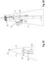
- FIG. 2A explains how the frame of the room detection device 30 can be put on and worn by a person 49.
- the first bracket 6 is shown without a cover, as shown in the Figures 1A and 1B is shown.
- the frame 1 is designed such that when the frame 1 is carried, the boom 7 is arranged in front of the person 49 when the person carries the frame 1 using the carrying device 2.
- the person 49 can, however, see through the two-part boom 7.
- the space detection device 30 is aligned in the vertical direction V by definition.
- the curved sections 10 of the shoulder supports 2-1 rest on the shoulders 50 of the person 49. In this way, part of the weight of the space detection device 30 is borne by the shoulders 50 of the person 49.
- the shoulder supports 2-1 prevent the space detection device 30 from tipping forwards around the attachment part 2-2 resting on the hip support 4.
- the attachment part 2-2 is located at the height of the hip area 51 of the person 49 when the person 49 carries the frame by means of the carrying device 2.
- the shoulder supports 2-1 rest on the shoulders 50 of the person 49.
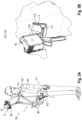
- the lower part of the room detection device 30 is shown in detail in Fig. 2B shown.
- the attachment part 2-2 rests on the hip support 4.
- the coupling of the attachment part 2-2 with the hip support 4 is shown in detail in the cross-sectional view of the Figure 4
- the contact part 2-2 is plate-shaped, whereby in the lower area it is Fig.4 shown, has two bends.
- the attachment part 2-2 has a transverse edge 2-3 at the bottom, which is aligned perpendicular to the direction of movement F of the person 49.
- the hip support 4 is U-shaped in the front part. In this area, the lower end of the attachment part 2-2 can be inserted so that the transverse edge 2-3 rests on the hip support 4, thereby Weight force of the space detection device 30 can be absorbed.
- the attachment part 2-2 thus corresponds to the hip support 4.
- the attachment part 2-2 is received by the U-shaped area of the hip support 4 in such a way that it is rotated about a transverse axis Y around the elongated transverse edge 2-3 of the attachment part 2-2 in the direction of the double arrow G from the Fig. 2A shown position can be tilted forwards.
- the person 40 lowers both shoulders 50 slightly so that the rear areas of the curved sections 10 of the shoulder supports 2-1 can be tilted forwards past the shoulders 50.
- the hip support 4 also has vertical cheeks 4-1. These prevent the attachment part 2-2 resting on the hip support 4 from pivoting about an axis perpendicular to the transverse axis Y. Lateral tilting of the frame 1 and rotation of the frame 1 relative to the hip support 4 about a vertical axis are thus prevented.
- the forward tilted state of the room detection device 30 is in the Figures 3A and 3B
- the first bracket 6 is shown without the cover, as shown in the Figures 1A and 1B is shown.
- the weight of the room detection device 30 is completely absorbed by the hip support 4.
- the hip support 4 can be attached to a hip belt 3 by means of the belt holder 4-2.
- the belt holder 4-2 can also be hooked into the belt of the person 49.
- the non-tilted state of the room detection device 30 ie in the operating state of the room detection device 30, as shown in Figure 2 A
- more than 50% of the weight of the space detection device 30 is supported by the hip support 4-2.
- the space detection device 30 is carried by a person 49, as shown in Fig. 2A is shown.
- the shoulder supports 2-1 prevent the space detection device 30 from tipping forwards. They therefore serve in particular for stabilization.
- the space detection device 30 can also be held by the handle 9 with the hands of the person 49 for stabilization.
- the vertical direction V results, as in Fig. 2A shown, a distance C between the shoulder supports 2-1 or a shoulder support 2-1 and the attachment part 2-2.
- the distance D is in a range from 400 mm to 800 mm, in particular in a range from 500 mm to 700 mm; in the present embodiment, this distance is 515 mm.
- the distance D is in a range from 300 mm to 500 mm, in particular in a range from 350 mm to 400 mm, and in the present embodiment is 372 mm.
- the distance E is in a range from 50 mm to 100 mm, in particular in a range from 60 mm to 80 mm. In the present embodiment, it is 72 mm.
- the first multiple scanner 31 is arranged above the cameras 32.
- the lowest area of the first holder 6 is far enough away from the vertices 11 of the shoulder supports 2-1 that the head of the person 49 wearing the spatial detection device 30 has a clear field of vision to the front. Furthermore, the distance D is large enough that the person 49 can wear a helmet on his head.
- the room detection device 30 could not be worn as stably by the person 49 in this case.
- the deflections when the person 49 moves at the height of the cameras 32' would also be much greater.
- a recording height of the images that is too high would be disadvantageous, as the resulting panoramic view would not correspond to the natural viewing height of a viewer.
- the arrangement of the cameras 32 above the head is also different from an arrangement at the head height of the person 49, as in Figure 2C designated by the reference numeral 32", advantageous because in this case an uninterrupted all-round recording is possible and the field of vision of the person 49 is not impaired.
- the blind spot which results from the cameras 32" and which is illustrated by the boundary line H can be minimized, while at the same time a practical use of the room detection device 30 is maintained when worn by a person 49.
- FIG 2D the arrangement of the cameras 32 in the embodiment of the spatial detection device 30 according to the invention is shown together with the boundary lines 50 which define the blind spot of the cameras 32. As shown, the person 49 is located within this blind spot.
- the room detection device 30 further comprises a reference marking 54 in the form of a notch on the attachment part 2-2. It is used to detect the position and/or orientation of the room detection device 30 relative to a stationary coordinate system with corresponding reference marks ("ground control points"), which in turn are attached to certain points in the environment to be detected, for example as stickers on the floors or walls of a building to be scanned, which are equipped with a crosshair and a unique designation or identification number.
- the room detection device 30 is held, for example briefly with the arrowhead of its reference marking 54, exactly to the crosshair of such a "ground control point” and the time and the unique designation or identification number of the "ground control point" are recorded. The exact time is recorded by actuating a separate actuation button 53, which is pressed as soon as the arrowhead and crosshair marking touch each other.
- the first multiple scanner 31 is attached to the first holder 6 such that the central axis X1 of its emission fan forms an angle ⁇ with the horizontal plane H2.
- the angle ⁇ is in a range from 5° to 20°. In the present embodiment, the angle ⁇ is 10°.
- the first multiple scanner 31 is thus tilted forward by 10°.
- the emission fan has an opening angle ⁇ 1. This opening angle is in a range from 10° to 40°. In the present embodiment, the angle ⁇ 1 is 30°.
- the second multiple scanner 36 is attached to the second holder 12 such that its central axis X2 is aligned vertically.
- the opening angle ⁇ 2 of the emission fan of the second multiple scanner 36 corresponds to the opening angle ⁇ 1 of the emission fan of the multiple scanner 31.
- the person 49 wearing the room detection device 30 is thus located outside the emission fans of the multiple scanners 31, 36.
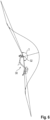
- each camera 32 is not a rotationally symmetrical cone. Rather, the opening angle is different in different directions.
- a vertical opening angle ⁇ results. This is in a range from 170° to 210°. In the present exemplary embodiment, this opening angle ⁇ is greater than 180°, namely 195.
- the vertical opening angle ⁇ is aligned such that the person 49, when wearing the space detection device 30, is predominantly outside the recording angle of the cameras 32.
- the horizontal distance of the camera 32 is selected to be as small as possible so that the area recorded by the cameras 32 in the immediate vicinity of the person 49 is as large as possible.
- Fig.7 explains how the room detection device 30 can be placed on a horizontal plane H3:
- contact points 37 are defined on which the spatial detection device 30 can lie freely on the horizontal plane H3 such that the first multiple scanner 31, the second multiple scanner 36 and the cameras 32 do not contact the horizontal plane H3.
- three contact points 37 are formed, namely at the rear edges of the shoulder supports 2-1 and at the attachment part 2-2.
- the frame 1 has a modified Figure 7
- the boom 7 has a middle joint 8.
- This middle joint 8 makes it possible to pivot the head area of the space detection device 30 towards the lower area in order to reduce the packing size of the space detection device 30.
- the middle Joint 8 has two locking positions: one locking position for the folded frame 1 and another locking position for the frame 1 in the operating state, as shown in Fig.7 is shown.
- the frame 1, for example the boom 7, can be taken apart and reassembled.
- the cameras 32 are connected to a control device 41.
- the control device 41 is in turn connected to a trigger 38, which is arranged near the handle 9 of the room detection device 30 so that the person 49 can activate the trigger 38 with his finger. If the person 49 activates the trigger 38, the control device 41 triggers a simultaneous image recording using the cameras 32.
- the control device 41 is also coupled to a timer 35, so that the time at which the camera 32 is triggered can be stored together with the images recorded by the cameras 32. For this purpose, the timer 35 is also connected to the evaluation device 42.
- the cameras 32 arranged in the head area of the room detection device 30 at the first holder 6 are connected via USB cable 44, the multiple scanner 31 via an Ethernet cable 52 to a bundling and synchronization interface 43, which is also arranged in the head area of the room detection device 30 at the first holder 6.
- the cameras 32 and the first multiple scanner 31 transmit the recorded data, including the time and angular position of the scanning device of the multiple scanner 31 and the intensity of each emitted and received signal pulse, to the bundling and synchronization interface 43.
- the bundling and synchronization interface 43 converts the received data and links it with time stamps generated by it so that it can be further transmitted via a collective data transmission cable 45, which is laid in the tubes of the frame 1, to the evaluation device 42, which is attached to the second holder 12 in the lower area of the room detection device 30.
- the first holder 6 also has the first receiving antenna 46 for a signal from a wireless network (WLAN/WiFi) and the second antenna 47 for receiving a wireless Bluetooth signal.
- the signals received by the two receiving antennas 46, 47 are transmitted to a signal processing unit 33, which is also arranged in the first holder 6, which forwards the data to the evaluation device 42 or alternatively, as in Figure 8 shown, to the bundling and synchronization interface 43 for further processing.
- an inertial measuring unit 34 is arranged in the first holder 6, which detects accelerations in the three spatial directions as well as rotation rates around three spatial axes, whereby the orientation or change in the orientation of the spatial detection device 30 in space can be determined.
- the data recorded by the inertial measuring unit 34 are sent to the evaluation device 42 or alternatively, as in Figure 8 shown, transferred to the bundling and synchronization interface 43 for further processing.
- a status sensor is also provided by the inertial measuring unit 34 or by a software-based evaluation module in the evaluation device 42, which evaluates the data of the inertial measuring unit 34, or by other sensors, in particular pressure sensors.
- This can detect how the frame 1 is carried by a person 49.
- the status sensor can in particular detect whether the frame 1 is at least partially carried by the shoulder support 2-1, as in Figure 2A is shown, or whether the frame 1 has been pivoted forward by means of the attachment part 2-2 and the hip support 4, and is therefore arranged tilted so that it no longer rests on the shoulders 50 of the person 49, as shown in Figure 3A shown, or whether it has been placed in a resting position as shown in Figure 7 is shown.
- the evaluation device 42 can calculate the direction and distance of an object in the object space that has been detected by means of the various scanning devices of the spatial detection device 30. In addition, further features of the surface of the detected objects can be determined if necessary.
- the evaluation device 42 generates a three-dimensional point cloud in real time, which represents the recorded object space. For this purpose, at least the reflected radiation detected by the receivers of the multiple scanners 31, 36 is used in the real-time calculation. Furthermore, the images recorded by the cameras 32 can also be used in the real-time processing and the generation of the three-dimensional Point cloud can be used. In this way, the evaluation device 42 calculates in real time a graphic representation of those areas of the object space through which the detection device 30 can be moved and/or has been moved. This graphic representation is output by the display 48. It is continuously updated when the object space is detected.
- the evaluation device 42 is coupled to a data interface 39.
- the data collected by the evaluation device 42 including the data already generated during operation of the room detection device 30, can be transferred to a memory for intermediate storage via this data interface 39.
- the data can also be transferred to an external data storage device during operation of the room detection device or after completion of a detection process.
- This data can then be used for post-processing.
- This post-processing produces a more precise point cloud of the detected object space. The computational effort for post-processing is so great that it cannot be carried out in real time by the evaluation device 42.
Landscapes
- Engineering & Computer Science (AREA)
- Physics & Mathematics (AREA)
- Remote Sensing (AREA)
- Radar, Positioning & Navigation (AREA)
- General Physics & Mathematics (AREA)
- Computer Networks & Wireless Communication (AREA)
- Electromagnetism (AREA)
- General Engineering & Computer Science (AREA)
- Mechanical Engineering (AREA)
- Signal Processing (AREA)
- Multimedia (AREA)
- Length Measuring Devices By Optical Means (AREA)
- Optical Radar Systems And Details Thereof (AREA)
- Stereoscopic And Panoramic Photography (AREA)
Claims (15)
- Armature (1) destinée à au moins un dispositif de balayage et conçue pour porter le dispositif de balayage par l'intermédiaire du corps d'une personne (49), l'armature (1) comprenant :un dispositif de port au corps (2) destiné à recevoir l'armature (1) pour permettre à la personne (49) de la porter, le dispositif de port au corps (2) comprenant une épaulière (2-1) destinée à faire reposer l'armature (1) sur les épaules (50) de la personne (49),ledit dispositif de port au corps (2) comprenant en outre une partie de contact (2-2) qui est reliée rigidement à l'épaulière (2-1) par l'intermédiaire d'un bras (7), la partie de contact (2-2) se trouvant à la hauteur de la zone de hanche (51) de la personne (49) lorsque la personne (49) porte l'armature (1) à l'aide du dispositif de port au corps (2), etledit dispositif de port au corps (2) comprenant en outre un support de hanche (4) qui correspond avec la partie de contact (2-2) ; etune section d'armature supérieure (5) à laquelle est fixé un premier support (6) destiné audit au moins un dispositif de balayage, le premier support (6) se trouvant au-dessus de la tête de la personne (49) lorsque la personne (49) porte ladite armature (1) au moyen du dispositif de port au corps (2),caractérisée en ce que
le support de hanche (4) coopère avec la partie de contact (2-2) de telle façon que la partie de contact (2-2) peut pivoter sur un premier axe qui est parallèle à un bord transversal allongé (2-3) de la partie de contact (4), lorsque le bord transversal allongé (2-3) de la partie de contact (2-2) repose sur le support de hanche (4), mais un pivotement sur un axe perpendiculaire au premier axe est empêché, si bien que la partie de contact (2-2) ne peut pivoter qu'autour d'un seul axe par rapport au support de hanche (4). - Armature (1) selon la revendication 1,
caractérisée en ce que
ladite armature (1) présente une articulation centrale (8) permettant de replier l'armature (1). - Armature (1) selon la revendication 1 ou 2,
caractérisée en ce que
le support de hanche (4) présente des joues verticales (4-2) qui empêchent la partie de contact (2-2) reposant sur le support de hanche (4) de pivoter sur un axe perpendiculaire au premier axe. - Armature (1) selon l'une des revendications précédentes,
caractérisée en ce que
l'épaulière (2-1) présente une section incurvée (10) dotée d'un sommet supérieur (11), et
la section incurvée (10), d'un côté du sommet (11), se fond dans ledit bras (7) et, de l'autre côté, présente à l'extrémité, dans la direction longitudinale de l'armature (1), une distance par rapport au sommet (11) qui se situe dans une plage de 50 à 100 mm. - Armature (1) selon l'une des revendications précédentes,
caractérisée en ce que
dans la direction longitudinale de l'armature (1), la distance (C) entre l'épaulière (2-1) et la partie de contact (2-2) se situe dans une plage de 400 à 800 mm. - Dispositif de relevé d'espace (30) comportant au moins un dispositif de balayage et une armature (1) selon l'une des revendications 1 à 5.
- Dispositif de relevé d'espace (30) selon la revendication 6,
caractérisé en ce que
le dispositif de balayage est un premier scanner multiple (31) et le premier scanner multiple (31) est fixé au premier support (6) de l'armature (1) au-dessus de la tête de la personne (49) lorsque la personne (49) porte le dispositif de relevé d'espace (30) à l'aide de l'armature (1). - Dispositif de relevé d'espace (30) selon la revendication 7,
caractérisé en ce que
le premier scanner multiple (31) est orienté de telle façon qu'un plan central balayé (X1) du premier scanner multiple (31) forme, avec un plan horizontal (H2), un premier angle (β) qui se situe dans une plage de 5 à 20° lorsque la personne (49) porte le dispositif de relevé d'espace (30) à l'aide de l'armature (1). - Dispositif de relevé d'espace (30) selon l'une des revendications 6 à 8,
caractérisé en ce que
au moins une caméra (32), et notamment une pluralité de caméras (32), est également fixée au premier support (6) de l'armature (1) au-dessus de la tête de la personne (49) lorsque la personne (49) porte le dispositif de relevé d'espace (30) à l'aide de l'armature (1), et l'angle de capture (γ) de la ou des caméras (32) se situe dans un plan vertical compris dans une plage de 170 à 210°, ladite personne (49) se trouvant hors de l'angle de capture (γ) de la ou des caméras (32), lorsque la personne (49) porte le dispositif de relevé d'espace (30) à l'aide de l'armature (1). - Dispositif de relevé d'espace (30) selon les revendications 7 à 9,
caractérisé en ce que
le premier scanner multiple (31) est disposé au-dessus des caméras (32). - Dispositif de relevé d'espace (30) selon l'une des revendications 6 à 10,
caractérisé en ce que
un deuxième support (12), auquel est fixé un deuxième scanner multiple (36), est disposé sur le bras (7) de l'armature (1). - Dispositif de relevé d'espace (30) selon la revendication 11,
caractérisé en ce que
le deuxième scanner multiple (36) est orienté de telle façon qu'un plan central balayé (X2) du deuxième scanner multiple (36) forme, avec un plan vertical, un deuxième angle qui se situe dans une plage de -10 à +10° lorsque ladite personne porte le dispositif de relevé d'espace (30) à l'aide de l'armature (1). - Dispositif de relevé d'espace (30) selon l'une des revendications 6 à 12,
caractérisé en ce que
l'armature (1) définit des points de placement (37) sur lesquels le dispositif de relevé d'espace (30) peut reposer librement sur un plan horizontal (H3) de telle façon que le premier scanner multiple (31) et/ou le deuxième scanner multiple (36) et/ou la ou les caméras (32) ne touchent pas le plan horizontal (H3). - Dispositif de relevé d'espace (30) selon l'une des revendications 6 à 13,
caractérisé en ce que
le dispositif de relevé d'espace (30) comporte au moins un repère permettant de détecter la position et/ou l'orientation du dispositif de relevé d'espace (30) par rapport à un système de coordonnées fixe. - Dispositif de relevé d'espace (30) selon l'une des revendications 9 à 14,
caractérisé en ce que
un dispositif d'évaluation (42) est fixé sur l'armature (1), au-dessous de la tête de la personne (49) lorsque la personne (49) porte le dispositif de relevé d'espace (30) à l'aide de l'armature (1), lequel dispositif d'évaluation est connecté aux caméras (32) et/ou au premier scanner multiple (31) pour un échange de données, la transmission des données s'effectuant par le biais d'une interface de mutualisation et de synchronisation (43), l'interface de mutualisation et de synchronisation (43) étant fixée au-dessus de la tête de la personne (49).
Applications Claiming Priority (2)
| Application Number | Priority Date | Filing Date | Title |
|---|---|---|---|
| DE102019120702.9A DE102019120702A1 (de) | 2019-07-31 | 2019-07-31 | Gestell für zumindest eine Scaneinrichtung und Raumerfassungsvorrichtung mit zumindest einer Scaneinrichtung |
| PCT/EP2020/071289 WO2021018900A1 (fr) | 2019-07-31 | 2020-07-28 | Bâti destiné à au moins un dispositif de balayage et dispositif de détection dans l'espace comportant au moins un dispositif de balayage |
Publications (3)
| Publication Number | Publication Date |
|---|---|
| EP4004586A1 EP4004586A1 (fr) | 2022-06-01 |
| EP4004586B1 true EP4004586B1 (fr) | 2024-07-24 |
| EP4004586C0 EP4004586C0 (fr) | 2024-07-24 |
Family
ID=71899723
Family Applications (1)
| Application Number | Title | Priority Date | Filing Date |
|---|---|---|---|
| EP20750209.7A Active EP4004586B1 (fr) | 2019-07-31 | 2020-07-28 | Bâti destiné à au moins un dispositif de balayage et dispositif de détection dans l'espace comportant au moins un dispositif de balayage |
Country Status (6)
| Country | Link |
|---|---|
| US (3) | US12011081B2 (fr) |
| EP (1) | EP4004586B1 (fr) |
| JP (1) | JP7378571B2 (fr) |
| CN (1) | CN114207473A (fr) |
| DE (1) | DE102019120702A1 (fr) |
| WO (1) | WO2021018900A1 (fr) |
Families Citing this family (7)
| Publication number | Priority date | Publication date | Assignee | Title |
|---|---|---|---|---|
| DE102021131129A1 (de) | 2021-11-26 | 2023-06-01 | Navvis Gmbh | Mobile vorrichtung und verfahren zum erfassen eines objektraums |
| EP4258015A1 (fr) * | 2022-04-08 | 2023-10-11 | Faro Technologies, Inc. | Système de support pour un appareil de balayage de coordonnées mobile |
| DE102022111649A1 (de) | 2022-05-10 | 2023-11-16 | Bayerische Motoren Werke Aktiengesellschaft | Aufsatz mit Raumerfassungsvorrichtung zur Aufnahme durch ein fahrerloses Transportsystem und Verfahren zum Erfassen von Objekträumen |
| DE102022111648A1 (de) | 2022-05-10 | 2023-11-16 | Bayerische Motoren Werke Aktiengesellschaft | Aufsatz mit Raumerfassungsvorrichtung zur Aufnahme durch ein fahrerloses Transportsystem und Verfahren zum Erfassen von Objekträumen |
| DE102022121770A1 (de) | 2022-08-29 | 2024-02-29 | Bayerische Motoren Werke Aktiengesellschaft | Verfahren zum kontaktlosen Einlesen von Referenzmarken |
| KR102875384B1 (ko) * | 2022-11-29 | 2025-10-22 | 한전케이디엔주식회사 | 카메라 왜곡에 맞춰 변형된 합성곱 필터를 활용한 지하 시설물 검출 시스템 및 방법 |
| WO2026037747A1 (fr) * | 2024-08-14 | 2026-02-19 | Navvis Gmbh | Dispositif de détection spatiale comprenant un dispositif de balayage, système de détection spatiale et procédé de détection de l'environnement |
Family Cites Families (22)
| Publication number | Priority date | Publication date | Assignee | Title |
|---|---|---|---|---|
| DE7308885U (de) * | 1973-07-05 | Mueller H | Schulterstativ | |
| DE1786195U (de) * | 1956-09-01 | 1959-04-02 | Erich Kuechler | Schulterstativ fuer kameras. |
| US4037763A (en) * | 1975-04-03 | 1977-07-26 | Video Components, Inc. | Instrument support |
| US4015759A (en) | 1975-05-27 | 1977-04-05 | Dreissigacker Peter D | Backpack frame having shoulder and hip supports with flexible connection to hip support |
| DE7600797U1 (de) * | 1976-01-14 | 1977-06-23 | Assmann, Hubert, 5760 Arnsberg | Am koerper tragbare haltevorrichtung fuer optische geraete |
| US6141034A (en) * | 1995-12-15 | 2000-10-31 | Immersive Media Co. | Immersive imaging method and apparatus |
| US6929409B2 (en) | 2003-01-21 | 2005-08-16 | Anton/Bauer, Inc. | Shoulder mounted support assembly to hold camera of camcorder |
| AT413452B (de) * | 2003-11-18 | 2006-03-15 | Riegl Laser Measurement Sys | Einrichtung zur aufnahme eines objektraumes |
| US20070031143A1 (en) * | 2005-08-05 | 2007-02-08 | Gregory Riccardi | Overhead camera support apparatus |
| DE102007001053B3 (de) * | 2007-01-03 | 2008-05-29 | Dirk Giesen | Stützvorrichtung, die am menschlichen Körper getragen wird und der Gewichtskraft des Oberkörpers in gebeugter Haltung entgegen wirkt |
| CN201182217Y (zh) * | 2008-03-04 | 2009-01-21 | 张惠珍 | 定位导航服 |
| WO2011053961A2 (fr) * | 2009-11-02 | 2011-05-05 | C & P Hiam Associates Llc | Sac à dos stable |
| EP2388615B1 (fr) * | 2010-05-17 | 2020-03-18 | Velodyne LiDAR, Inc. | Système lidar haute définition |
| AT510579B1 (de) * | 2010-12-21 | 2012-05-15 | Riegl Laser Measurement Systems Gmbh | Laser-scanner und verfahren zur vermessung von zielräumen |
| US20120328279A1 (en) * | 2011-06-24 | 2012-12-27 | David Raizman | Shoulder Mounted Camera Support and Stabilizer |
| US8941777B1 (en) * | 2012-10-31 | 2015-01-27 | Google Inc. | System and method for capturing images of a geographic area |
| EP2913796B1 (fr) * | 2014-02-26 | 2019-03-27 | NavVis GmbH | Procédé de génération de vues panoramiques sur un système mobile de cartographie |
| EP3333541A3 (fr) * | 2014-05-05 | 2019-07-03 | Hexagon Technology Center GmbH | Système de relevé |
| JP6594686B2 (ja) | 2015-07-14 | 2019-10-23 | 東急建設株式会社 | 三次元形状計測装置、三次元形状計測方法、及びプログラム |
| FR3046053B1 (fr) * | 2015-12-24 | 2017-12-22 | Sagem Defense Securite | Module de pied pour une structure d'exosquelette |
| CN109154661A (zh) * | 2016-03-19 | 2019-01-04 | 威力登激光雷达有限公司 | 用于基于lidar的3-d成像的集成照射和检测 |
| AU2017236723A1 (en) | 2016-03-22 | 2018-08-30 | Mitsubishi Electric Corporation | Measurement device |
-
2019
- 2019-07-31 DE DE102019120702.9A patent/DE102019120702A1/de active Pending
-
2020
- 2020-07-28 CN CN202080056103.3A patent/CN114207473A/zh active Pending
- 2020-07-28 WO PCT/EP2020/071289 patent/WO2021018900A1/fr not_active Ceased
- 2020-07-28 EP EP20750209.7A patent/EP4004586B1/fr active Active
- 2020-07-28 JP JP2022502937A patent/JP7378571B2/ja active Active
- 2020-07-28 US US17/631,307 patent/US12011081B2/en active Active
-
2024
- 2024-06-13 US US18/742,004 patent/US12433390B2/en active Active
-
2025
- 2025-10-06 US US19/350,376 patent/US20260090625A1/en active Pending
Also Published As
| Publication number | Publication date |
|---|---|
| WO2021018900A1 (fr) | 2021-02-04 |
| US12433390B2 (en) | 2025-10-07 |
| EP4004586A1 (fr) | 2022-06-01 |
| US20240324756A1 (en) | 2024-10-03 |
| DE102019120702A1 (de) | 2021-02-04 |
| JP7378571B2 (ja) | 2023-11-13 |
| JP2022544002A (ja) | 2022-10-17 |
| CN114207473A (zh) | 2022-03-18 |
| US12011081B2 (en) | 2024-06-18 |
| US20220257001A1 (en) | 2022-08-18 |
| EP4004586C0 (fr) | 2024-07-24 |
| US20260090625A1 (en) | 2026-04-02 |
Similar Documents
| Publication | Publication Date | Title |
|---|---|---|
| EP4004586B1 (fr) | Bâti destiné à au moins un dispositif de balayage et dispositif de détection dans l'espace comportant au moins un dispositif de balayage | |
| EP2765388B1 (fr) | Contrôleur de terrain mobile destiné à arpentage et commande à distance | |
| EP2156139B1 (fr) | Dispositif et procédé pour l'acquisition sans contact de coordonnées spatiales d'une surface | |
| EP2918972B1 (fr) | Procédé et appareil de mesure d'éloignement portatif pour la génération d'un modèle spatial | |
| EP2458328B1 (fr) | Dispositif de mesure et de construction doté d'une fonctionnalité de recherche de point d'aplomb automatique | |
| DE102016105858A1 (de) | Mobiles dreidimensionales Messinstrument | |
| EP3894785A1 (fr) | Dispositif de mesure, système de mesure et instruments d'aide à la mesure | |
| DE112014007231T5 (de) | Verwendung eines zweidimensionalen Scanners zur Beschleunigung der Registrierung von dreidimensionalen Scandaten | |
| DE112016002057T5 (de) | Dreidimensionales messgerät, lösbar verkoppelt mit einem roboterarm auf einer motorisierten mobilen plattform | |
| DE102021131129A1 (de) | Mobile vorrichtung und verfahren zum erfassen eines objektraums | |
| EP3182065A1 (fr) | Télémètre portatif et procédé de détection de positions relatives | |
| EP3775993A1 (fr) | Dispositif mobile et procédé de détection d'un espace objet | |
| DE112013004569T5 (de) | Verfahren zur Verwendung eines tragbaren Geräts zum Auswählen, festen Anvisieren und Verfolgen eines Retroreflektors mit einem Lasertracker | |
| DE102015122845A1 (de) | Verfahren zum optischen Abtasten und Vermessen einer Umgebung mittels einer 3D-Messvorrichtung und Auswertung im Netzwerk | |
| EP2607841A2 (fr) | Système optique | |
| DE102015122846A1 (de) | Verfahren zum optischen Abtasten und Vermessen einer Umgebung mittels einer 3D-Messvorrichtung und Nahfeldkommunikation | |
| DE102015106838B4 (de) | Verfahren zur Steuerung einer 3D-Messvorrichtung mittels des Bewegungspfades und Vorrichtung hierzu | |
| DE102014019669B4 (de) | 16Verfahren zum optischen Abtasten und Vermessen einer Umgebung mit einer 3D-Messvorrichtung und Autokalibrierung mit vorgegebenen Bedingungen | |
| EP3037837B1 (fr) | Procédé et système de détermination de position d'au moins un dispositif de communication mobile comprenant un dispositif de détection d'image numérique | |
| DE102025131643A1 (de) | Raumerfassungsvorrichtung mit einer Scaneinrichtung, Raumerfassungssystem und Verfahren zum Erfassen der Umgebung | |
| HK40074832B (en) | Frame for at least one scanning apparatus and spatial capturing device having at least one scanning apparatus | |
| HK40074832A (en) | Frame for at least one scanning apparatus and spatial capturing device having at least one scanning apparatus | |
| WO2025120092A1 (fr) | Télémètre laser et système doté d'un télémètre laser |
Legal Events
| Date | Code | Title | Description |
|---|---|---|---|
| STAA | Information on the status of an ep patent application or granted ep patent |
Free format text: STATUS: UNKNOWN |
|
| STAA | Information on the status of an ep patent application or granted ep patent |
Free format text: STATUS: THE INTERNATIONAL PUBLICATION HAS BEEN MADE |
|
| PUAI | Public reference made under article 153(3) epc to a published international application that has entered the european phase |
Free format text: ORIGINAL CODE: 0009012 |
|
| STAA | Information on the status of an ep patent application or granted ep patent |
Free format text: STATUS: REQUEST FOR EXAMINATION WAS MADE |
|
| 17P | Request for examination filed |
Effective date: 20211208 |
|
| AK | Designated contracting states |
Kind code of ref document: A1 Designated state(s): AL AT BE BG CH CY CZ DE DK EE ES FI FR GB GR HR HU IE IS IT LI LT LU LV MC MK MT NL NO PL PT RO RS SE SI SK SM TR |
|
| DAV | Request for validation of the european patent (deleted) | ||
| DAX | Request for extension of the european patent (deleted) | ||
| REG | Reference to a national code |
Ref country code: HK Ref legal event code: DE Ref document number: 40074832 Country of ref document: HK |
|
| GRAP | Despatch of communication of intention to grant a patent |
Free format text: ORIGINAL CODE: EPIDOSNIGR1 |
|
| STAA | Information on the status of an ep patent application or granted ep patent |
Free format text: STATUS: GRANT OF PATENT IS INTENDED |
|
| INTG | Intention to grant announced |
Effective date: 20240222 |
|
| GRAS | Grant fee paid |
Free format text: ORIGINAL CODE: EPIDOSNIGR3 |
|
| GRAA | (expected) grant |
Free format text: ORIGINAL CODE: 0009210 |
|
| STAA | Information on the status of an ep patent application or granted ep patent |
Free format text: STATUS: THE PATENT HAS BEEN GRANTED |
|
| AK | Designated contracting states |
Kind code of ref document: B1 Designated state(s): AL AT BE BG CH CY CZ DE DK EE ES FI FR GB GR HR HU IE IS IT LI LT LU LV MC MK MT NL NO PL PT RO RS SE SI SK SM TR |
|
| REG | Reference to a national code |
Ref country code: GB Ref legal event code: FG4D Free format text: NOT ENGLISH |
|
| REG | Reference to a national code |
Ref country code: CH Ref legal event code: EP |
|
| REG | Reference to a national code |
Ref country code: IE Ref legal event code: FG4D Free format text: LANGUAGE OF EP DOCUMENT: GERMAN Ref country code: DE Ref legal event code: R096 Ref document number: 502020008684 Country of ref document: DE |
|
| U01 | Request for unitary effect filed |
Effective date: 20240801 |
|
| U07 | Unitary effect registered |
Designated state(s): AT BE BG DE DK EE FI FR IT LT LU LV MT NL PT SE SI Effective date: 20240822 |
|
| U20 | Renewal fee for the european patent with unitary effect paid |
Year of fee payment: 5 Effective date: 20240912 |
|
| PG25 | Lapsed in a contracting state [announced via postgrant information from national office to epo] |
Ref country code: NO Free format text: LAPSE BECAUSE OF FAILURE TO SUBMIT A TRANSLATION OF THE DESCRIPTION OR TO PAY THE FEE WITHIN THE PRESCRIBED TIME-LIMIT Effective date: 20241024 |
|
| PG25 | Lapsed in a contracting state [announced via postgrant information from national office to epo] |
Ref country code: PL Free format text: LAPSE BECAUSE OF FAILURE TO SUBMIT A TRANSLATION OF THE DESCRIPTION OR TO PAY THE FEE WITHIN THE PRESCRIBED TIME-LIMIT Effective date: 20240724 Ref country code: GR Free format text: LAPSE BECAUSE OF FAILURE TO SUBMIT A TRANSLATION OF THE DESCRIPTION OR TO PAY THE FEE WITHIN THE PRESCRIBED TIME-LIMIT Effective date: 20241025 |
|
| PG25 | Lapsed in a contracting state [announced via postgrant information from national office to epo] |
Ref country code: IS Free format text: LAPSE BECAUSE OF FAILURE TO SUBMIT A TRANSLATION OF THE DESCRIPTION OR TO PAY THE FEE WITHIN THE PRESCRIBED TIME-LIMIT Effective date: 20241124 |
|
| PG25 | Lapsed in a contracting state [announced via postgrant information from national office to epo] |
Ref country code: HR Free format text: LAPSE BECAUSE OF FAILURE TO SUBMIT A TRANSLATION OF THE DESCRIPTION OR TO PAY THE FEE WITHIN THE PRESCRIBED TIME-LIMIT Effective date: 20240724 |
|
| PG25 | Lapsed in a contracting state [announced via postgrant information from national office to epo] |
Ref country code: RS Free format text: LAPSE BECAUSE OF FAILURE TO SUBMIT A TRANSLATION OF THE DESCRIPTION OR TO PAY THE FEE WITHIN THE PRESCRIBED TIME-LIMIT Effective date: 20241024 Ref country code: ES Free format text: LAPSE BECAUSE OF FAILURE TO SUBMIT A TRANSLATION OF THE DESCRIPTION OR TO PAY THE FEE WITHIN THE PRESCRIBED TIME-LIMIT Effective date: 20240724 |
|
| PG25 | Lapsed in a contracting state [announced via postgrant information from national office to epo] |
Ref country code: RS Free format text: LAPSE BECAUSE OF FAILURE TO SUBMIT A TRANSLATION OF THE DESCRIPTION OR TO PAY THE FEE WITHIN THE PRESCRIBED TIME-LIMIT Effective date: 20241024 Ref country code: PL Free format text: LAPSE BECAUSE OF FAILURE TO SUBMIT A TRANSLATION OF THE DESCRIPTION OR TO PAY THE FEE WITHIN THE PRESCRIBED TIME-LIMIT Effective date: 20240724 Ref country code: NO Free format text: LAPSE BECAUSE OF FAILURE TO SUBMIT A TRANSLATION OF THE DESCRIPTION OR TO PAY THE FEE WITHIN THE PRESCRIBED TIME-LIMIT Effective date: 20241024 Ref country code: IS Free format text: LAPSE BECAUSE OF FAILURE TO SUBMIT A TRANSLATION OF THE DESCRIPTION OR TO PAY THE FEE WITHIN THE PRESCRIBED TIME-LIMIT Effective date: 20241124 Ref country code: HR Free format text: LAPSE BECAUSE OF FAILURE TO SUBMIT A TRANSLATION OF THE DESCRIPTION OR TO PAY THE FEE WITHIN THE PRESCRIBED TIME-LIMIT Effective date: 20240724 Ref country code: GR Free format text: LAPSE BECAUSE OF FAILURE TO SUBMIT A TRANSLATION OF THE DESCRIPTION OR TO PAY THE FEE WITHIN THE PRESCRIBED TIME-LIMIT Effective date: 20241025 Ref country code: ES Free format text: LAPSE BECAUSE OF FAILURE TO SUBMIT A TRANSLATION OF THE DESCRIPTION OR TO PAY THE FEE WITHIN THE PRESCRIBED TIME-LIMIT Effective date: 20240724 |
|
| REG | Reference to a national code |
Ref country code: CH Ref legal event code: PL |
|
| PG25 | Lapsed in a contracting state [announced via postgrant information from national office to epo] |
Ref country code: RO Free format text: LAPSE BECAUSE OF FAILURE TO SUBMIT A TRANSLATION OF THE DESCRIPTION OR TO PAY THE FEE WITHIN THE PRESCRIBED TIME-LIMIT Effective date: 20240724 Ref country code: SM Free format text: LAPSE BECAUSE OF FAILURE TO SUBMIT A TRANSLATION OF THE DESCRIPTION OR TO PAY THE FEE WITHIN THE PRESCRIBED TIME-LIMIT Effective date: 20240724 |
|
| PG25 | Lapsed in a contracting state [announced via postgrant information from national office to epo] |
Ref country code: MC Free format text: LAPSE BECAUSE OF FAILURE TO SUBMIT A TRANSLATION OF THE DESCRIPTION OR TO PAY THE FEE WITHIN THE PRESCRIBED TIME-LIMIT Effective date: 20240724 Ref country code: CH Free format text: LAPSE BECAUSE OF NON-PAYMENT OF DUE FEES Effective date: 20240731 |
|
| PG25 | Lapsed in a contracting state [announced via postgrant information from national office to epo] |
Ref country code: CZ Free format text: LAPSE BECAUSE OF FAILURE TO SUBMIT A TRANSLATION OF THE DESCRIPTION OR TO PAY THE FEE WITHIN THE PRESCRIBED TIME-LIMIT Effective date: 20240724 |
|
| PG25 | Lapsed in a contracting state [announced via postgrant information from national office to epo] |
Ref country code: SK Free format text: LAPSE BECAUSE OF FAILURE TO SUBMIT A TRANSLATION OF THE DESCRIPTION OR TO PAY THE FEE WITHIN THE PRESCRIBED TIME-LIMIT Effective date: 20240724 |
|
| PLBE | No opposition filed within time limit |
Free format text: ORIGINAL CODE: 0009261 |
|
| STAA | Information on the status of an ep patent application or granted ep patent |
Free format text: STATUS: NO OPPOSITION FILED WITHIN TIME LIMIT |
|
| 26N | No opposition filed |
Effective date: 20250425 |
|
| REG | Reference to a national code |
Ref country code: GB Ref legal event code: 732E Free format text: REGISTERED BETWEEN 20250612 AND 20250618 |
|
| PG25 | Lapsed in a contracting state [announced via postgrant information from national office to epo] |
Ref country code: IE Free format text: LAPSE BECAUSE OF NON-PAYMENT OF DUE FEES Effective date: 20240728 |
|
| U70 | Rights in rem or legal means of execution for european patent with unitary effect registered |
Designated state(s): AT BE BG DE DK EE FI FR IT LT LU LV MT NL PT SE SI Effective date: 20250708 |
|
| U20 | Renewal fee for the european patent with unitary effect paid |
Year of fee payment: 6 Effective date: 20250731 |
|
| PGFP | Annual fee paid to national office [announced via postgrant information from national office to epo] |
Ref country code: GB Payment date: 20250722 Year of fee payment: 6 |
|
| PG25 | Lapsed in a contracting state [announced via postgrant information from national office to epo] |
Ref country code: CY Free format text: LAPSE BECAUSE OF FAILURE TO SUBMIT A TRANSLATION OF THE DESCRIPTION OR TO PAY THE FEE WITHIN THE PRESCRIBED TIME-LIMIT; INVALID AB INITIO Effective date: 20200728 |
|
| PG25 | Lapsed in a contracting state [announced via postgrant information from national office to epo] |
Ref country code: HU Free format text: LAPSE BECAUSE OF FAILURE TO SUBMIT A TRANSLATION OF THE DESCRIPTION OR TO PAY THE FEE WITHIN THE PRESCRIBED TIME-LIMIT; INVALID AB INITIO Effective date: 20200728 |