EP4004972B1 - Appareil et procédé de pré-alignement de plaquette - Google Patents
Appareil et procédé de pré-alignement de plaquette Download PDFInfo
- Publication number
- EP4004972B1 EP4004972B1 EP20848244.8A EP20848244A EP4004972B1 EP 4004972 B1 EP4004972 B1 EP 4004972B1 EP 20848244 A EP20848244 A EP 20848244A EP 4004972 B1 EP4004972 B1 EP 4004972B1
- Authority
- EP
- European Patent Office
- Prior art keywords
- rotation
- carriage
- rotational member
- axis
- sensor unit
- Prior art date
- Legal status (The legal status is an assumption and is not a legal conclusion. Google has not performed a legal analysis and makes no representation as to the accuracy of the status listed.)
- Active
Links
Images




Classifications
-
- H—ELECTRICITY
- H10—SEMICONDUCTOR DEVICES; ELECTRIC SOLID-STATE DEVICES NOT OTHERWISE PROVIDED FOR
- H10P—GENERIC PROCESSES OR APPARATUS FOR THE MANUFACTURE OR TREATMENT OF DEVICES COVERED BY CLASS H10
- H10P72/00—Handling or holding of wafers, substrates or devices during manufacture or treatment thereof
- H10P72/50—Handling or holding of wafers, substrates or devices during manufacture or treatment thereof for positioning, orientation or alignment
- H10P72/53—Handling or holding of wafers, substrates or devices during manufacture or treatment thereof for positioning, orientation or alignment using optical controlling means
-
- H—ELECTRICITY
- H10—SEMICONDUCTOR DEVICES; ELECTRIC SOLID-STATE DEVICES NOT OTHERWISE PROVIDED FOR
- H10P—GENERIC PROCESSES OR APPARATUS FOR THE MANUFACTURE OR TREATMENT OF DEVICES COVERED BY CLASS H10
- H10P72/00—Handling or holding of wafers, substrates or devices during manufacture or treatment thereof
- H10P72/06—Apparatus for monitoring, sorting, marking, testing or measuring
- H10P72/0606—Position monitoring, e.g. misposition detection or presence detection
- H10P72/0608—Position monitoring, e.g. misposition detection or presence detection of substrates stored in a container, a magazine, a carrier, a boat or the like
-
- H—ELECTRICITY
- H10—SEMICONDUCTOR DEVICES; ELECTRIC SOLID-STATE DEVICES NOT OTHERWISE PROVIDED FOR
- H10P—GENERIC PROCESSES OR APPARATUS FOR THE MANUFACTURE OR TREATMENT OF DEVICES COVERED BY CLASS H10
- H10P72/00—Handling or holding of wafers, substrates or devices during manufacture or treatment thereof
- H10P72/70—Handling or holding of wafers, substrates or devices during manufacture or treatment thereof for supporting or gripping
- H10P72/76—Handling or holding of wafers, substrates or devices during manufacture or treatment thereof for supporting or gripping using mechanical means, e.g. clamps or pinches
- H10P72/7604—Handling or holding of wafers, substrates or devices during manufacture or treatment thereof for supporting or gripping using mechanical means, e.g. clamps or pinches the wafers being placed on a susceptor, stage or support
- H10P72/7624—Handling or holding of wafers, substrates or devices during manufacture or treatment thereof for supporting or gripping using mechanical means, e.g. clamps or pinches the wafers being placed on a susceptor, stage or support characterised by the mechanical construction of the susceptor, stage or support
Definitions
- the present invention relates to semiconductor wafer processing.
- Some methods used to identify the orientation of the wafer can include providing a notch on a perimeter of the wafer, and utilizing a device to rotate the wafer such that the notch can be detected by a sensor in order to determine that the wafer is oriented at the desired orientation.
- US 2002/097905 A1 discloses an apparatus comprising a base; a drive device disposed on the base, the drive device having an output shaft with a wafer receiving surface, the drive device being configured to rotate the output shaft about an axis of rotation; a sensor unit disposed on the base, the sensor unit being configured to sense a wafer received on the wafer receiving surface; and an engagement device configured to engage and disengage a translational mechanism between the drive device and the sensor unit,
- the present invention provides another apparatus according to independent claim 1, and another method according to independent claim 9.
- the dependent claims show further preferred embodiments of the said apparatus and method, respectively.
- the present disclosure advantageously provides an apparatus comprising: a base; a drive device disposed on the base, the drive device having an output shaft with a wafer receiving surface, the drive device being configured to rotate the output shaft about an axis of rotation; a sensor unit disposed on the base, the sensor unit being configured to sense a wafer received on the wafer receiving surface; and an engagement device configured to engage and disengage a translational mechanism between the drive device and the sensor unit, wherein, when the engagement device engages the translational mechanism, rotation of the output shaft about the axis of rotation by the drive device changes a relative positional relationship between the sensor unit and the axis of rotation.
- the present disclosure additionally advantageously provides a method comprising: providing an apparatus comprising: a base; a drive device disposed on the base, the drive device having an output shaft with a wafer receiving surface, the drive device being configured to rotate the output shaft about an axis of rotation; a sensor unit disposed on the base, the sensor unit being configured to sense a wafer received on the wafer receiving surface, and an engagement device configured to engage and disengage a translational mechanism between the drive device and the sensor unit; engaging the translational mechanism between the drive device and the sensor unit, and rotating the output shaft about the axis of rotation by the drive device to change a relative positional relationship between the sensor unit and the axis of rotation; and disengaging the translational mechanism between the drive device and the sensor unit, and rotating the output shaft about the axis of rotation by the drive device to rotate the wafer on the wafer receiving surface.
- a semiconductor wafer pre-alignment apparatus is described herein that advantageously accommodates various semiconductor wafer diameters.
- Semiconductor wafers can be provided with a notch or marking that can be used to identify an orientation of the wafer, in order to ensure that the wafer is in a desired orientation for processing. For example, a single notch can be provided on a perimeter of the wafer.
- a pre-alignment apparatus is provided with a wafer platform that supports and rotates the wafer, and a stationary read head that scans an edge of the wafer as it rotates, such an apparatus has distinct disadvantages. With such an apparatus, a range of a sensor of the read head may be only 20 mm, so the sensor must be positioned radially for different diameter wafers.
- the semiconductor wafer pre-alignment apparatus described herein advantageously uses a same motor to both rotate the wafer and radially move the read head to allow for use with different sizes of wafers.
- an actuator such as an air cylinder or solenoid
- the rotational gear is rigidly affixed to the rotation motor. Once engaged, the motor can drive the rack and the read head to the appropriate radial position.
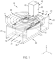
- FIG. 1 depicts an apparatus 100 that can be used, for example, as a semiconductor wafer alignment apparatus to align a semiconductor wafer for inspection and/or for processing.
- the apparatus 100 can advantageously be used with semiconductor wafers having various diameters, as can be seen from concentric circles 10 shown in FIG. 1 .
- the apparatus 100 includes a base 200, a drive device 300, a sensor unit 400, and an engagement device 600.
- the base 200 shown in FIG. 1 includes a housing (or outer housing) 210 including an upper wall 212, a lower wall 214, a first side wall 216, a second side wall 218, a third side wall 220, and a fourth side wall 222.
- the upper wall 212 includes an opening 224 for a portion of the drive device 300 to extend therethrough.
- the upper wall 212 further includes a slot 226 for a portion of the sensor unit 400 to extend therethrough. The slot 226 allows for relative movement between the sensor unit 400 and the drive device 300.
- the base 200 can either be mounted to a support in a stationary manner, for example, by fixing the base 200 with respect to a floor of a manufacturing facility, or in a movable manner, for example, by mounting the base 200 on a movable stage that can provide for movement with respect to the floor along one or more of an X axis, a Y axis, and a Z axis by using drive motors.
- the base 200 can be mounted by mounting the lower wall 214 to the support, or by mounting one of the other walls of the housing 210 to the support.
- the drive device 300 is disposed on the base 200.
- the drive device 300 has an output shaft 302 with a wafer platform 304 mounted to a distal end 303 of the output shaft 302.
- the wafer platform 304 having a wafer receiving surface 306 that is configured to receive a semiconductor wafer.
- the wafer receiving surface 306 supports the wafer (see circles 10), and can be provided with a surface material that provides friction between the wafer and the wafer receiving surface 306 to prevent the wafer from moving in relation to the wafer receiving surface 306.
- the wafer receiving surface 306 can be provided with suction holes and the wafer platform 304 can be provided with a suction device to hold the wafer onto the wafer receiving surface 306 to prevent the wafer from moving in relation to the wafer receiving surface 306.
- the wafer platform 304 can be fixed to the distal end 303 of the output shaft 302 such that the wafer platform 304 does not rotate relative to the output shaft 302.
- the wafer platform 304 can be coupled to the distal end 303 such that the wafer platform 304 can selectively rotate relative to the output shaft 302 or not rotate relative to the output shaft 302, for example, using a clutch configured to engage and disengage transmission of rotation of the output shaft 302 to rotation of the wafer platform 304.
- the drive device 300 is configured to rotate the output shaft 302 about an axis of rotation 302a.
- the drive device 300 can be, for example, an electric motor.
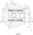
- the drive device 300 includes a housing 310 that is mounted to the housing 210. In the embodiment shown in FIGS. 1-4 , the housing 310 is mounted in a stationary manner to the upper wall 212; however, the housing 310 could alternatively be mounted to another wall of the housing 210 of the base 200.
- the drive device 300 includes a stator 312 that is mounted in a fixed relationship to the housing 310, and a rotor 314 that rotates in relation to the stator 312.
- the rotor 314 is supported via bearings 316 by a rotational support 315 that is mounted in a fixed relationship to the housing 310.
- the output shaft 302 is part of or connected to the rotor 314 such that rotation of the rotor 314 results in rotation of the output shaft 302 about the axis of rotation 302a.
- the output shaft 302 includes a lower portion 318 having a lower end 320.
- a rotational member 322 is coupled to the lower end 320 of the output shaft 302.
- the rotational member 322 can be fixed to the lower end 320 such that the rotational member 322 does not rotate relative to the output shaft 302.
- the rotational member 322 can be coupled to the lower end 320 such that the rotational member 322 can selectively rotate relative to the output shaft 302 or not rotate relative to the output shaft 302, for example, using a clutch configured to engage and disengage transmission of rotation of the output shaft 302 to rotation of the rotational member 322.
- the sensor unit 400 is disposed on the base 200.
- the sensor unit 400 being configured to sense a wafer received on the wafer receiving surface 306.
- the sensor unit 400 including a read head 402 having an optical sensor 404 facing in a -Z direction towards an upper surface of the wafer (see, e.g., FIGS. 3 and 6 ) that can sense the wafer, such as edges thereof or marks/notches formed thereon, within a sensing area 406 in order to align a semiconductor wafer for inspection and/or for processing.
- the read head 402 being mounted to a support member 408 that extends from within the housing 210 through the slot 226.
- the apparatus 100 includes a translational mechanism 500 between the drive device 300 and the sensor unit 400.
- the translational mechanism 500 includes a carriage 410 that is slidably coupled the base 200, and the sensor unit 400 is mounted on the carriage 410 via the support member 406, which is mounted to the carriage 410.
- the housing 310 of the drive device 300 is mounted to the housing 210 of the base 200, and first slide members 330 and 332 are mounted to opposing outer surfaces of the housing 310.
- the first slide members 330 and 332 could be directly mounted to walls of the housing 210.
- the carriage 410 includes second slide members 412 and 414 that are fixedly thereto.
- the second slide members 412 and 414 being slidably supported by the first slide members 330 and 332, respectively, to allow the carriage 410 to slide along the X axis.
- the first slide members 330 and 332 have respective slots 331 and 333 that longitudinally extending along the X axis
- the second slide members 412 and 414 are slide rails that are provided within the slots 331 and 333, respectively; however, alternatively the second slide members 412 and 414 could be provided with slots that longitudinally extending along the X axis and the first slide members 330 and 332 could be slide rails that are provided within the slots.
- the translational mechanism 500 further includes the rotational member 322 coupled to the output shaft 302, and a linear member 440 connected to the carriage 410.
- the linear member 440 is a rack having a linear arrangement of teeth 441.
- the linear member 440 is mounted on a bottom plate 442, which is mounted to the second slide members 412 and 414 by flexures 450 and 460, respectively.
- the linear member 440 is connected to the carriage 410 via the bottom plate 442 and the flexures 450 and 460.
- Upper ends 452 and 462 of the flexures 450 and 460 are fixedly mounted to the second slide members 412 and 414, and lower ends 454 and 464 of the flexures 450 and 460 are fixedly mounted to opposite side of the bottom plate 442.
- the flexures 450 and 460 are flexible elements can bend when a cantilever force is applied to the lower ends 454 and 464 about the fixed upper ends 452 and 462.
- the carriage 410, the bottom plate 442, and the flexure members 450 and 460 form a four-bar linkage.
- the engagement device 600 is configured to engage and disengage the translational mechanism 500 between the drive device 300 and the sensor unit 400 such that, when the engagement device 600 engages the translational mechanism, rotation of the output shaft 302 about the axis of rotation 302a by the drive device 300 changes a relative positional relationship between the sensor unit 400 and the axis of rotation 302a, and thus change a relative positional relationship between the sensor unit 400 and the wafer receiving surface 306. Also, when the engagement device 600 disengages the translational mechanism 500, rotation of the output shaft 302 about the axis of rotation 302a by the drive device 300 does not change the relative positional relationship between the sensor unit 400 and the axis of rotation 302a.
- the engagement device 600 includes an actuator 602 configured to move the linear member 440 into contact with an outer circumferential surface 324 of the rotational member 322 to engage the linear member 440 to the rotational member 322.
- the actuator 602 is configured to move the linear member 440 into contact with the outer circumferential surface 324 of the rotational member 322 to engage teeth 441 of the linear member 440 with teeth 326 on the outer circumferential surface 324 of the rotational member 322.
- the actuator 602 is an air cylinder 610 that upon actuation extends piston rod 612 along the Y axis.
- the actuator 600 could alternatively be a solenoid.
- the air cylinder 610 has a first end 611 with a support member 613 that connects the first end 611 to a bracket 614.
- the bracket 614 is mounted to the carriage 410 to maintain the first end 611 of the air cylinder in a fixed relationship with the carriage 410.
- the piston rod 612 has a coupling member 616 mounted to a terminal end thereof.
- the coupling member 616 extends and retracts along the Y axis with the movement of the piston rod 612.
- the coupling member 616 is coupled by a pin 618 to a connecting member 620 that is fixedly mounted to the bottom plate 442.
- Actuation of the actuator 602 bends the flexure members 450 and 460 to move the linear member 440 into contact with the outer circumferential surface 324 of the rotational member 322 to engage the linear member 440 to the rotational member 322.
- the air cylinder 610 extends piston rod 612 along the Y axis, thereby moving the coupling member 616 along the Y axis, which pushes bottom plate 442 via the pin 618 and connecting member 620, thereby bending the flexure members 450 and 460 and moving the linear member 440 mounted to the bottom plate 442.
- actuation of the actuator 602 moves the linear member 440 from a disengaged position in which the teeth 441 of the linear member 440 are not engaged to the teeth 326 of the rotational member 322 to an engaged position in which the teeth 441 of the linear member 440 are engaged to (i.e., meshed with) the teeth 326 of the rotational member 322.
- the air cylinder 610 retracts piston rod 612 along the Y axis (e.g.
- An amount of bending or deflection of the flexure members 450 and 460 can be determined, for example, based on a distance needed to move between an engaged state and a disengaged state of the teeth 441 and 326 (e.g. based on a height of the teeth 441 of the linear member 440 and a height of the teeth 326 of the rotational member 322) and a predetermined clearance distance. In an embodiment in which no teeth are present, but rather a frictional engagement is used, then an amount of bending or deflection of the flexure members 450 and 460 can be determined, for example, based on a predetermined clearance distance.
- the linear member 440, the bottom plate 442, the flexures 450 and 460, and the carriage 410 are driven in the direction along the X axis such that the second slide members 412 and 414 slide along the first slide members 330 and 332, respectively, to allow the carriage 410 and the sensor unit 400 to slide in the direction along the X axis.
- the change in the relative positional relationship between the sensor unit 400 and the axis of rotation 302a allows for the apparatus 100 to be used with a variety of different diameter semiconductor wafers, such that the relative positional relationship between the sensor unit 400 and the axis of rotation 302a can be adjusted so that the sensing area 406 of the optical sensor 404 can be aligned with an outer edge area of the wafer.
- the sensor unit 400 and the axis of rotation 302a can be adjusted to be closer to each other for use with wafers of smaller diameter, and the sensor unit 400 and the axis of rotation 302a can be adjusted to be farther from each other for use with wafers of larger diameter.
- the apparatus 100 can be used to perform alignment of the semiconductor wafer for inspection and/or for processing by using the drive device 300 to rotate the wafer and the optical sensor 404 to scan the wafer in the sensing area 406.
- the engagement device 600 is configured to engage and disengage a coupling 550 between the drive device 300 and the carriage 410.
- the coupling 550 includes the rotational member 322 and the linear member 440.
- the drive device 300 and the carriage 410 are coupled together such that the rotation of the output shaft 302 by the drive device 300 in clockwise and counterclockwise directions will result in translational movement of the sensor unit 400 along the X axis to change a relative positional relationship between the sensor unit 400 and the axis of rotation 302a by moving the sensor unit 400 closer to or farther away from the axis of rotation 302a, and thus change a relative positional relationship between the sensor unit 400 and the wafer receiving surface 306.
- FIGS. 8A and 8B show an embodiment in which rotational member 322a is configured as a gear having an outer circumferential surface 324a with teeth 326a provided thereon. Additionally, linear member 440a is mounted on bottom plate 442a. The linear member 440a is configured as a rack having a linear arrangement of teeth 441a. FIGS. 8A and 8B show the linear member 440a engaged to the rotational member 322a (i.e., the linear member 440a is in the engaged position in which the teeth 441a of the linear member 440a are engaged to the teeth 326a of the rotational member 322a).
- FIGS. 9-12 show alternative embodiments of the invention.
- FIG. 9 show an embodiment in which rotational member 322b is has an outer circumferential surface 324b that is frictionally engageable with a surface 441b of the linear member 440b.
- the outer circumferential surface 324b and/or the surface 441b can provided with surface material that provides friction between these surface when these surfaces are in contact with one another in order to prevent these surfaces from slipping in relation to one another when the rotational member 322b is rotated.
- FIG. 9 shows the linear member 440b engaged to the rotational member 322b (i.e., the outer circumferential surface 324b is in contact with the surface 441b). Therefore, in this engaged state, rotation of the rotational member 322b in the counterclockwise direction (as shown in FIG.
- FIGS. 10A and 10B show an embodiment in which rotational member 322c is provided with a belt and pulley arrangement to transfer rotation of the rotational member 322c to translation of the sensor unit.
- the drive device includes pulleys 340c and 342c rotatably mounted to the housing of the drive device.
- the rotational member 322c has an outer circumferential surface 324c that drives a belt 344c about pulleys 340c and 342c.
- the belt 344c is fixed to member 440c, which is mounted on bottom plate 442c.
- a clutch 323c is provided at the juncture between a lower end of the output shaft of the drive device and the rotational member 322c.
- the clutch 323c is configured to engage and disengage power transmission from the rotation of the output shaft to the rotation of the rotational member 322c.
- FIGS. 10A and 10B show the member 440c engaged to the rotational member 322c due to an engaged state of the clutch 323c and presence of the belt 344c. Therefore, in this engaged state, rotation of the rotational member 322c in the counterclockwise direction (as shown in FIG. 10A ) will result in translational movement of the bottom plate 442c (as well as the connected carriage and sensor unit) along the X axis in a first direction 20c by sliding second sliding member 412c along first sliding member 330c. (For simplicity of the drawings, only one first sliding member and one second sliding member are shown in FIGS.
- the clutch described above and below can be any conventional clutch that allows for engagement and disengagement of power transmission from the rotation of the output shaft to the rotation of the rotational member.
- a clutch such as is described above with respect to FIGS. 10A and 10B , could be incorporated into any of the embodiments shown in FIGS. 1-9 as the engagement device 600, thereby eliminating the need for actuator 602 and eliminating the need for movement of the bottom plate in the direction of the Y axis.
- the rotational member and the linear member can remain in an engaged state, and the clutch can be used to engage or disengage power transmission from the rotation of the output shaft to the rotation of the rotational member and thus engage or disengage power transmission of the output shaft from rotating the rotational member and thus driving the movement of the linear member.
- the flexures could be made of a more rigid material.
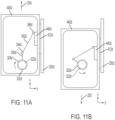
- FIGS. 11A and 11B show an embodiment in which rotational member 322d is provided with a member 340d fixedly connected to the rotational member 322d.
- the member 340d can extend from an outer circumferential surface 424d of the rotational member 322d as shown or can be provided on an outer edge of the rotational member 322d at a location spaced apart from the axis of rotation of the rotational member 322d.
- the member 340d is pivotally connected to an arm member 342d by a first pivot joint 344d.
- the arm member 342d is pivotally connected to member 440d by a second pivot joint 346d to provide a linkage between the rotational member 322d and the member 440d.
- the member 440d is mounted on bottom plate 442d.
- a clutch 323d is provided at the juncture between a lower end of the output shaft of the drive device and the rotational member 322d.
- the clutch 323d is configured to engage and disengage power transmission from the rotation of the output shaft to the rotation of the rotational member 322d.
- FIGS. 11A and 11B show the member 440d engaged to the rotational member 322d due to an engaged state of the clutch 323d and presence of the linkage including arm member 342d. Therefore, in this engaged state, rotation of the rotational member 322d in the clockwise direction (as shown in FIG.
- FIG. 12 shows an embodiment in which rotational member 322e is provided with a drive arm 340e fixedly connected to the rotational member 322e and extending from an outer circumferential surface 424e of the rotational member 322e.
- the drive arm 340e having an elongated shape with a cam slot 342e extending longitudinally along the drive arm 340e.
- a cam follower 344e is fixedly mounted on member 440e.
- the member 440e is mounted on bottom plate 442e which is connected to the carriage via the flexures.
- the apparatus of the present invention advantageously provides a drive device that can be used both to rotate a semiconductor wafer about an axis of rotation and to adjust a positional relationship between a sensor unit and the axis of rotation.
- the adjustment of the positional relationship between the sensor unit and the axis of rotation advantageously allows the apparatus to be used with various sizes of semiconductor wafers with a wide range of diameters.
- the apparatus 100 can be utilized, for example, by placing a semiconductor wafer on the wafer receiving surface 306 of the wafer platform 304, engaging the engagement device 600 by actuating actuator 602 to bend flexures 450 and 460 to engage teeth 441 with teeth 326, actuate the drive device 300 to rotate the output shaft 302 and the rotational member 322 in order to drive the carriage 410 and sensor unit 400 in a direction along the X axis toward the axis of rotation 302a, and utilize the optical sensor 404 to detect the presence or absence of the semiconductor wafer in the sensing area 406.
- the drive device 330 and/or the engagement device 600 can be deactivated to stop the movement of the carriage 410 and sensor unit 400 in the direction along the X axis toward the axis of rotation 302a.
- the apparatus 100 can be used to perform alignment of the semiconductor wafer for inspection and/or for processing by using the drive device 300 to rotate the wafer and the optical sensor 404 to scan the wafer in the sensing area 406.
- the apparatus 100 advantageously allows for adjustment of the relative positional relationship between the sensor unit 400 and the axis of rotation 302 using a same drive device used to rotate the semiconductor wafer about the axis of rotation.
- the change in the relative positional relationship between the sensor unit 400 and the axis of rotation 302a allows for the apparatus 100 to be used with a variety of different diameter semiconductor wafers, such that the relative positional relationship between the sensor unit 400 and the axis of rotation 302a can be adjusted so that the sensing area 406 of the optical sensor 404 can be aligned with an outer edge area of the wafer.
- the sensor unit 400 and the axis of rotation 302a can be adjusted to be closer to each other for use with wafers of smaller diameter, and the sensor unit 400 and the axis of rotation 302a can be adjusted to be farther from each other for use with wafers of larger diameter.
- FIG. 13 depicts an embodiment of a clutch 700 that is configured to engage and disengage power transmission from rotation of the output shaft 302 of the drive device 300 to rotation of a rotational member 702, and engage and disengage power transmission from the rotation of the output shaft 302 of the drive device 300 to the linear member 440 engaged to the rotational member 702.
- Clutch 700 can be used with rotational member 702 configured as a gear having an outer circumferential surface 703 with teeth provided thereon, and a linear member 440 configured as a rack having a linear arrangement of teeth 441, as contemplated by the depiction in FIG. 13 .
- clutch 700 could be used as a clutch with any of the other embodiments shown herein.
- the clutch 700 includes a drive device 710 that is configured to drive a shaft 704 upon which the rotational member 702 is mounted in the Z direction.
- the drive device 710 could be an air cylinder, solenoid, etc. that drives the shaft 704 in a linear direction and that passively allows rotation of the shaft 704, so that the rotational member 702 can be driven in rotation by the drive device 300 when the rotational member 702 is engaged to the output shaft 302.
- the lower end 320 of the output shaft 302 has a disk 320a with a lower engagement surface 321.
- an upper engagement surface 706 of the rotational member 302 contacts and thus engages (e.g., frictionally, using grooves, teeth, etc.) the lower engagement surface 321, and once the drive device 710 is no longer actuated then the drive shaft 704 will move in the -Z direction and the rotational member 702 will disengage from the output shaft 302. It is noted that the amount of movement of the shaft 704 in order to perform this engagement can be small, and is exaggerated in FIG. 13 for purposes of illustration.
- the teeth on the outer circumferential surface 703 can slide with respect to teeth 441, and the components can slide or flex (e.g., belt 344c, member 340d, arm member 342d) in relation to one another in the other embodiments in order to allow for this small relative movement.
- the components can slide or flex (e.g., belt 344c, member 340d, arm member 342d) in relation to one another in the other embodiments in order to allow for this small relative movement.
- the shaft 704 can be rotationally mounted using bearing 720.
- An outer periphery of the bearing 720 can be rigidly mounted to the drive device 710 by mounting bracket 724 that is mounted to lower wall 214 as shown or can be rigidly mounted directly to the lower wall 214.
- An inner periphery of the bearing 720 is slidably engaged to slides 722 that are fixed to the shaft 704, in order to allow movement of the shaft 704 along the Z axis and also allow rotation of the shaft 704 about the Z axis.
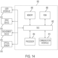
- FIG. 14 illustrates an embodiment of a computer 800 with which an embodiment of the invention may be implemented.
- computer 800 is depicted with respect to a particular device or equipment, it is contemplated that other devices or equipment (e.g., network elements, servers, etc.) within FIG. 14 can deploy the illustrated hardware and components of system 800.
- the computer 800 is programmed (e.g., via computer program code or instructions) to provide the functionality described herein and includes a communication mechanism such as a bus 802 for passing information between other internal and external components of the computer system 800.
- One or more processors 804 for processing information are coupled with the bus 802 to perform a set of operations on information as specified by computer program code.
- the computer 800 also includes a memory 806 coupled to bus 810.
- the memory 806 is also used by the processor 804 to store temporary values during execution of processor instructions.
- the computer system 800 also includes a read only memory (ROM) 808 or other static storage device coupled to the bus 802 for storing static information, including instructions, that is not changed by the computer system 800.
- the computer 800 includes a communication interface 810 that allows the computer 800 to communicate with other devices or equipment (e.g., network elements, servers, etc.)
- Information is provided to the bus 802 for use by the processor 804 from a user interface 812, such as a keyboard containing alphanumeric keys operated by a human user, a display device, a pointing device (such as a mouse or a trackball or cursor direction keys).
- a user interface 812 such as a keyboard containing alphanumeric keys operated by a human user, a display device, a pointing device (such as a mouse or a trackball or cursor direction keys).
- a drive device 814 (e.g., drive device 300) can communicate with the processor 804 via the bus 802 in order to send and receive data, operating instructions/commands, or other information therebetween.
- the processor 804 can control operation of the drive device 814 using operating instructions/commands in order to control rotation (e.g., start, stop, direction (e.g., clockwise, counterclockwise), speed, etc.) of an output shaft (such as output shaft 302) of the drive device 814.
- An engagement device 816 (e.g. actuator 602, clutch 323c, clutch 323d, clutch 323e, etc.) can communicate with the processor 804 via the bus 802 in order to send and receive data, operating instructions/commands, or other information therebetween.
- the processor 804 can control operation of the engagement device 816 using operating instructions/commands in order to control actuation of the engagement device 816.
- An optical sensor 818 (e.g. optical sensor 404) can communicate with the processor 804 via the bus 802 in order to send and receive data, operating instructions/commands, or other information therebetween.
- the processor 804 can control operation of the optical sensor 818 using operating instructions/commands in order to control operation of the optical sensor 818 in conjunction with the operation of the drive device 814 and/or the engagement device 818.
- a semiconductor wafer can be placed on a wafer receiving surface of a wafer platform, the processor 804 (either using instructions entered by a user via the user interface 812 or instructions stored in memory 806) sends a command to the engagement device 816 to actuate, the processor 804 (either using instructions entered by a user via the user interface 812 or instructions stored in memory 806) sends a command to the drive device 814 to rotate the output shaft in order to drive the optical sensor 818 in a direction along the X axis toward the axis of rotation, and the processor 804 (either using instructions entered by a user via the user interface 812 or instructions stored in memory 806) sends a command to the optical sensor 818 to detect the presence or absence of the semiconductor wafer.
- the processor 804 sends commands to the drive device 814 and/or the engagement device 816 to deactivate to stop the movement of the optical sensor 818 in the direction along the X axis toward the axis of rotation.
- the process 804 can perform alignment of the semiconductor wafer for inspection and/or for processing by using the drive device 814 to rotate the wafer and the optical sensor 818 to scan the wafer in the sensing area.
Landscapes
- Container, Conveyance, Adherence, Positioning, Of Wafer (AREA)
- Mechanical Treatment Of Semiconductor (AREA)
Claims (11)
- Appareil (100), comprenant :une base (200) ;un dispositif d'entraînement (300) disposé sur la base (200), le dispositif d'entraînement (300) ayant un arbre de sortie (302) avec une surface de réception de plaquette (306), le dispositif d'entraînement (300) étant configuré pour faire tourner l'arbre de sortie (302) autour d'un axe de rotation (302a) ;une unité de capteur (400) disposée sur la base (200), l'unité de capteur (400) étant configurée pour détecter une plaquette reçue sur la surface de réception de plaquette (306) ; etun dispositif de prise (600) configuré pour mettre en prise et hors prise un mécanisme de translation (500) entre le dispositif d'entraînement (300) et l'unité de capteur (400),dans lequel l'appareil (100) est caractérisé en ce que :
lorsque le dispositif de prise (600) est en prise avec le mécanisme de translation (500), une rotation de l'arbre de sortie (302) autour de l'axe de rotation (302a) par le dispositif d'entraînement (300) modifie une relation de position relative entre l'unité de capteur (400) et l'axe de rotation (302a). - Appareil (100) selon la revendication 1, dans lequel, lorsque le dispositif de prise (600) est hors prise du mécanisme de translation (500), la rotation de l'arbre de sortie (302) autour de l'axe de rotation (302a) par le dispositif d'entraînement (300) ne modifie pas la relation de position relative entre l'unité de capteur (400) et l'axe de rotation (302a).
- Appareil (100) selon la revendication 1,dans lequel le mécanisme de translation (500) comprend :un élément de rotation (322) couplé à l'arbre de sortie (302) ;un chariot (410) couplé de manière coulissante à la base (200), l'unité de capteur (400) étant montée sur le chariot (410) ; etun élément linéaire (440) relié au chariot (410),dans lequel une surface circonférentielle extérieure (324b) de l'élément de rotation (322) peut être mise en prise avec l'élément linéaire (440) lors d'un actionnement du dispositif de prise (600) de sorte qu'une rotation de l'élément de rotation (322) déplace le chariot (410) par rapport à l'axe de rotation (302a),dans lequel le dispositif de prise (600) comprend un actionneur (602) configuré pour déplacer l'élément linéaire (440) en contact avec la surface circonférentielle extérieure (324b) pour mettre en prise l'élément linéaire (440) avec l'élément de rotation (322),dans lequel l'élément linéaire (440) est monté sur le chariot (410) par des éléments de flexion (450, 460) de sorte qu'un actionnement de l'actionneur (602) plie les éléments de flexion (450, 460) pour déplacer l'élément linéaire (440) en contact avec la surface circonférentielle extérieure (324b) pour mettre en prise l'élément linéaire (440) avec l'élément de rotation (322), etdans lequel le chariot (410), l'élément linéaire (440) et les éléments de flexion (450, 460) forment une liaison à quatre barres.
- Appareil (100) selon la revendication 1,dans lequel le mécanisme de translation (500) comprend :un élément de rotation (322) couplé à l'arbre de sortie (302) ;un chariot (410) couplé de manière coulissante à la base (200), l'unité de capteur (400) étant montée sur le chariot (410) ; etun élément linéaire (440) relié au chariot (410),dans lequel une surface circonférentielle extérieure (324b) de l'élément de rotation (322) peut être mise en prise avec l'élément linéaire (440) lors d'un actionnement du dispositif de prise (600) de sorte qu'une rotation de l'élément de rotation (322) déplace le chariot (410) par rapport à l'axe de rotation (302a),dans lequel le dispositif de prise (600) comprend un actionneur (602) configuré pour déplacer l'élément linéaire (440) en contact avec la surface circonférentielle extérieure (324b) afin de mettre en prise l'élément linéaire (440) avec l'élément de rotation (322),dans lequel l'élément de rotation (322) est un engrenage, etdans lequel l'élément linéaire (440) est une crémaillère présentant un agencement linéaire de dents (441), l'engrenage pouvant être mis en prise avec les dents (441).
- Appareil (100) selon la revendication 1,dans lequel le mécanisme de translation (500) comprend :un élément de rotation (322) couplé à l'arbre de sortie (302) ;un chariot (410) couplé de manière coulissante à la base (200), l'unité de capteur (400) étant montée sur le chariot (410) ; etun élément linéaire (440) relié au chariot (410),dans lequel une surface circonférentielle extérieure (324b) de l'élément de rotation (322) peut être mise en prise avec l'élément linéaire (440) lors d'un actionnement du dispositif de prise (600) de sorte que la rotation de l'élément de rotation (322) déplace le chariot (410) par rapport à l'axe de rotation (302a),dans lequel le dispositif de prise (600) comprend un actionneur (602) configuré pour déplacer l'élément linéaire (440) en contact avec la surface circonférentielle extérieure (324b) pour mettre en prise l'élément linéaire (440) avec l'élément de rotation (322), etdans lequel la surface circonférentielle extérieure (324b) de l'élément de rotation (322) peut être mise en prise par friction avec une surface de l'élément linéaire (440).
- Appareil (100) selon la revendication 1, comprenant en outre un élément de rotation (322) couplé à l'arbre de sortie (302),dans lequel le dispositif de prise (600) est un embrayage (323c) configuré pour mettre en prise et hors prise la transmission de rotation de l'arbre de sortie (302) à une rotation de l'élément de rotation (322),dans lequel le mécanisme de translation (500) comprend un chariot (410) couplé de manière coulissante à la base (200), l'unité de capteur (400) étant montée sur le chariot (410),dans lequel le mécanisme de translation (500) comprend en outre un élément d'entraînement reliant l'élément de rotation (322) au chariot (410) de sorte qu'une rotation de l'élément de rotation (322) déplace le chariot (410) par rapport à l'axe de rotation (302a),dans lequel l'élément d'entraînement est un élément linéaire (440) relié au chariot (410), l'élément linéaire (440) étant en prise avec une surface circonférentielle extérieure (324b) de l'élément de rotation (322) de sorte qu'une rotation de l'élément de rotation (322) déplace le chariot (410) par rapport à l'axe de rotation (302a),dans lequel l'élément de rotation (322) est un engrenage, etdans lequel l'élément linéaire (440) est une crémaillère ayant un agencement linéaire de dents (441), l'engrenage étant en prise avec les dents (441).
- Appareil (100) selon la revendication 1, comprenant en outre un élément de rotation (322) couplé à l'arbre de sortie (302),dans lequel le dispositif de prise (600) est un embrayage configuré pour mettre en prise et hors prise la transmission de rotation de l'arbre de sortie (302) à une rotation de l'élément de rotation (322),dans lequel le mécanisme de translation (500) comprend un chariot (410) couplé de manière coulissante à la base (200), l'unité de capteur (400) étant montée sur le chariot (410),dans lequel le mécanisme de translation (500) comprend en outre un élément d'entraînement reliant l'élément de rotation (322) au chariot (410) de sorte qu'une rotation de l'élément de rotation (322) déplace le chariot (410) par rapport à l'axe de rotation (302a),dans lequel l'élément d'entraînement est un élément linéaire (440) relié au chariot (410), l'élément linéaire (440) étant en prise avec une surface circonférentielle extérieure (324b) de l'élément de rotation (322) de sorte qu'une rotation de l'élément de rotation (322) déplace le chariot (410) par rapport à l'axe de rotation (302a), etdans lequel la surface circonférentielle extérieure (324b) de l'élément de rotation (322) est en prise par friction avec une surface de l'élément linéaire (440).
- Appareil (100) selon la revendication 1, comprenant en outre un élément de rotation (322) couplé à l'arbre de sortie (302),dans lequel le dispositif de prise (600) est un embrayage configuré pour mettre en prise et hors prise la transmission de rotation de l'arbre de sortie (302) à une rotation de l'élément de rotation (322),dans lequel le mécanisme de translation (500) comprend un chariot (410) couplé de manière coulissante à la base (200), l'unité de capteur (400) étant montée sur le chariot (410),dans lequel le mécanisme de translation (500) comprend en outre un élément d'entraînement reliant l'élément de rotation (322) au chariot (410) de sorte qu'une rotation de l'élément de rotation (322) déplace le chariot (410) par rapport à l'axe de rotation (302a), etdans lequel :l'élément d'entraînement est un agencement de courroie et de poulie, la courroie (334c) étant entraînée par l'élément de rotation (322), et la courroie (334c) étant reliée au chariot (410) ;l'élément d'entraînement est une liaison comprenant un élément de bras ayant une première extrémité reliée de manière pivotante à l'élément de rotation (322) et une deuxième extrémité reliée de manière pivotante au chariot (410) ; oul'élément d'entraînement est un bras d'entraînement comportant une fente de came, et le chariot (410) comprend un suiveur de came disposé à l'intérieur de la fente de came.
- Procédé, comprenant :la fourniture d'un appareil (100), comprenant :une base (200) ;un dispositif d'entraînement (300) disposé sur la base (200), le dispositif d'entraînement (300) ayant un arbre de sortie (302) avec une surface de réception de plaquette (306), le dispositif d'entraînement (300) étant configuré pour faire tourner l'arbre de sortie (302) autour d'un axe de rotation (302a) ;une unité de capteur (400) disposée sur la base (200), l'unité de capteur (400) étant configurée pour détecter une plaquette reçue sur la surface de réception de plaquette (306), etun dispositif de prise (600) configuré pour mettre en prise et hors prise un mécanisme de translation (500) entre le dispositif d'entraînement (300) et l'unité de capteur (400) ;dans lequel le procédé est caractérisé par :la mise en prise du mécanisme de translation (500) entre le dispositif d'entraînement (300) et l'unité de capteur (400), et la rotation de l'arbre de sortie (302) autour de l'axe de rotation (302a) par le dispositif d'entraînement (300) pour modifier une relation de position relative entre l'unité de capteur (400) et l'axe de rotation (302a) ; etla mise hors prise du mécanisme de translation (500) entre le dispositif d'entraînement (300) et l'unité de capteur (400), et la rotation de l'arbre de sortie (302) autour de l'axe de rotation (302a) par le dispositif d'entraînement (300) pour faire tourner la plaquette sur la surface de réception de plaquette (306).
- Procédé selon la revendication 9, dans lequel, lorsque le mécanisme de translation (500) est mis hors prise, la rotation de l'arbre de sortie (302) autour de l'axe de rotation (302a) par le dispositif d'entraînement ne modifie pas la relation de position relative entre l'unité de capteur (400) et l'axe de rotation (302a).
- Procédé selon la revendication 9, comprenant en outre :
l'utilisation de l'unité de capteur (400) pour détecter un alignement de la plaquette lorsque le mécanisme de translation (500) est hors prise et que l'arbre de sortie (302) est tourné par le dispositif d'entraînement (300).
Applications Claiming Priority (2)
| Application Number | Priority Date | Filing Date | Title |
|---|---|---|---|
| US16/523,944 US10867822B1 (en) | 2019-07-26 | 2019-07-26 | Wafer pre-alignment apparatus and method |
| PCT/US2020/043656 WO2021021691A1 (fr) | 2019-07-26 | 2020-07-27 | Appareil et procédé de pré-alignement de plaquette |
Publications (4)
| Publication Number | Publication Date |
|---|---|
| EP4004972A1 EP4004972A1 (fr) | 2022-06-01 |
| EP4004972A4 EP4004972A4 (fr) | 2023-11-01 |
| EP4004972B1 true EP4004972B1 (fr) | 2025-03-05 |
| EP4004972C0 EP4004972C0 (fr) | 2025-03-05 |
Family
ID=73746952
Family Applications (1)
| Application Number | Title | Priority Date | Filing Date |
|---|---|---|---|
| EP20848244.8A Active EP4004972B1 (fr) | 2019-07-26 | 2020-07-27 | Appareil et procédé de pré-alignement de plaquette |
Country Status (9)
| Country | Link |
|---|---|
| US (1) | US10867822B1 (fr) |
| EP (1) | EP4004972B1 (fr) |
| JP (1) | JP7665591B2 (fr) |
| KR (1) | KR102766878B1 (fr) |
| CN (1) | CN114207799B (fr) |
| ES (1) | ES3015609T3 (fr) |
| PL (1) | PL4004972T3 (fr) |
| TW (1) | TWI838564B (fr) |
| WO (1) | WO2021021691A1 (fr) |
Families Citing this family (1)
| Publication number | Priority date | Publication date | Assignee | Title |
|---|---|---|---|---|
| CN118053724A (zh) * | 2022-11-10 | 2024-05-17 | 中微半导体设备(上海)股份有限公司 | 一种半导体处理设备 |
Family Cites Families (30)
| Publication number | Priority date | Publication date | Assignee | Title |
|---|---|---|---|---|
| US3930684A (en) | 1971-06-22 | 1976-01-06 | Lasch Jr Cecil A | Automatic wafer feeding and pre-alignment apparatus and method |
| US4676649A (en) | 1985-11-27 | 1987-06-30 | Compact Spindle Bearing Corp. | Multi-axis gas bearing stage assembly |
| US5238354A (en) | 1989-05-23 | 1993-08-24 | Cybeq Systems, Inc. | Semiconductor object pre-aligning apparatus |
| JPH0736417B2 (ja) * | 1989-10-24 | 1995-04-19 | 株式会社メツクス | ウエハーの位置決め装置 |
| JP3223584B2 (ja) * | 1992-06-10 | 2001-10-29 | 株式会社ダイヘン | 半導体ウエハのセンタ合せ装置及び方法 |
| US5799858A (en) | 1995-09-16 | 1998-09-01 | Samsung Aerospace Industries, Ltd. | Die bonding device |
| KR0165350B1 (ko) | 1995-12-13 | 1999-02-18 | 김광호 | 반도체웨이퍼 공급장치 |
| US5773951A (en) | 1996-03-25 | 1998-06-30 | Digital Test Corporation | Wafer prober having sub-micron alignment accuracy |
| JP3592075B2 (ja) | 1998-04-16 | 2004-11-24 | 松下電器産業株式会社 | 円板形状体の位置決め装置 |
| WO1999064207A1 (fr) | 1998-06-08 | 1999-12-16 | Genmark Automation, Inc. | Dispositif de prealignement pour substrats incorpore dans un systeme robotique |
| KR100307825B1 (ko) | 1999-10-23 | 2001-11-02 | 윤종용 | 웨이퍼 예비정렬 스테이지에 사용되는 웨이퍼 온도 제어장치 |
| US6468022B1 (en) * | 2000-07-05 | 2002-10-22 | Integrated Dynamics Engineering, Inc. | Edge-gripping pre-aligner |
| DE10102540B4 (de) | 2001-01-19 | 2013-03-21 | Vistec Semiconductor Systems Jena Gmbh | Anordnung und Verfahren zur Identifikation von Substraten |
| JP4615149B2 (ja) * | 2001-05-31 | 2011-01-19 | 株式会社ダイヘン | ウェハのノッチ合せ装置 |
| CA2476389A1 (fr) | 2002-03-22 | 2003-10-09 | Electro Scientific Industries, Inc. | Appareil d'alignement de sondes d'essais |
| JP4258828B2 (ja) | 2002-06-06 | 2009-04-30 | 株式会社安川電機 | ウエハプリアライメント装置および方法 |
| KR100724579B1 (ko) | 2006-02-01 | 2007-06-04 | 삼성전자주식회사 | 웨이퍼 프리 얼라인먼트 유니트를 갖는 노광설비 및 이를이용한 웨이퍼 프리 얼라인먼트 방법 |
| JP5006173B2 (ja) | 2007-12-04 | 2012-08-22 | 平田機工株式会社 | アライナおよびそれを用いたエッジクランプ検出方法 |
| JP2011124298A (ja) | 2009-12-09 | 2011-06-23 | Yaskawa Electric Corp | プリアライナ装置およびそれを備えた搬送システム |
| CN102049730B (zh) * | 2010-12-29 | 2012-02-15 | 清华大学 | 一种用于化学机械抛光设备的晶圆交换装置 |
| KR20120105669A (ko) * | 2011-03-16 | 2012-09-26 | 주식회사 로보스타 | 에지 그립식 프리-얼라이너 |
| CN102141739B (zh) * | 2011-04-01 | 2013-01-16 | 清华大学 | 光刻机硅片台双台交换系统 |
| JP2013153108A (ja) | 2012-01-26 | 2013-08-08 | Yaskawa Electric Corp | 基板位置決め装置 |
| JP6179012B2 (ja) * | 2013-07-28 | 2017-08-16 | アテル株式会社 | ウエハ位置決め装置 |
| KR101882823B1 (ko) | 2013-12-31 | 2018-07-27 | 상하이 마이크로 일렉트로닉스 이큅먼트(그룹) 컴퍼니 리미티드 | 실리콘 웨이퍼 프리 얼라인 장치 및 그 방법 |
| JP6523991B2 (ja) | 2015-04-14 | 2019-06-05 | 株式会社荏原製作所 | 基板処理装置および基板処理方法 |
| CN106292194B (zh) | 2015-05-24 | 2018-03-30 | 上海微电子装备(集团)股份有限公司 | 硅片传输系统 |
| CN107561864B (zh) | 2016-06-30 | 2019-10-25 | 上海微电子装备(集团)股份有限公司 | 边缘曝光装置和方法 |
| US10041789B2 (en) | 2016-09-30 | 2018-08-07 | Axcelis Technologies, Inc. | Integrated emissivity sensor alignment characterization |
| JP6210525B1 (ja) | 2017-02-20 | 2017-10-11 | レーザーテック株式会社 | アライメント方法及びアライメント装置 |
-
2019
- 2019-07-26 US US16/523,944 patent/US10867822B1/en active Active
-
2020
- 2020-07-27 JP JP2022505457A patent/JP7665591B2/ja active Active
- 2020-07-27 KR KR1020227006217A patent/KR102766878B1/ko active Active
- 2020-07-27 PL PL20848244.8T patent/PL4004972T3/pl unknown
- 2020-07-27 ES ES20848244T patent/ES3015609T3/es active Active
- 2020-07-27 TW TW109125303A patent/TWI838564B/zh active
- 2020-07-27 CN CN202080053597.XA patent/CN114207799B/zh active Active
- 2020-07-27 WO PCT/US2020/043656 patent/WO2021021691A1/fr not_active Ceased
- 2020-07-27 EP EP20848244.8A patent/EP4004972B1/fr active Active
Also Published As
| Publication number | Publication date |
|---|---|
| JP2022541668A (ja) | 2022-09-26 |
| ES3015609T3 (en) | 2025-05-06 |
| CN114207799B (zh) | 2025-04-29 |
| TWI838564B (zh) | 2024-04-11 |
| EP4004972A4 (fr) | 2023-11-01 |
| PL4004972T3 (pl) | 2025-08-18 |
| EP4004972C0 (fr) | 2025-03-05 |
| WO2021021691A1 (fr) | 2021-02-04 |
| KR102766878B1 (ko) | 2025-02-11 |
| EP4004972A1 (fr) | 2022-06-01 |
| JP7665591B2 (ja) | 2025-04-21 |
| US10867822B1 (en) | 2020-12-15 |
| TW202111847A (zh) | 2021-03-16 |
| KR20220037494A (ko) | 2022-03-24 |
| CN114207799A (zh) | 2022-03-18 |
Similar Documents
| Publication | Publication Date | Title |
|---|---|---|
| CN110712195B (zh) | 运送机器人和机器人系统 | |
| JP5495826B2 (ja) | タイヤ選別装置 | |
| EP0235047B1 (fr) | Dispositif pour le montage de puces | |
| EP4004972B1 (fr) | Appareil et procédé de pré-alignement de plaquette | |
| KR102793608B1 (ko) | 웨이퍼 프리-얼라이너 및 웨이퍼 사전 정렬 방법 | |
| JP6498353B2 (ja) | ターンテーブル | |
| CN117080143A (zh) | 一种半导体定位装置 | |
| JP2002359277A (ja) | ウェハのノッチ合せ装置 | |
| JP3873393B2 (ja) | 板材の折り曲げ機 | |
| US6640660B2 (en) | Pick-up and placement apparatus | |
| JP6856692B2 (ja) | ロードポート | |
| CN116551342B (zh) | 圆周不规则物料的组装装置及其工作方法 | |
| JP7306533B2 (ja) | 搬送ロボットおよびロボットシステム | |
| CN223877014U (zh) | 取料机构和机械手 | |
| KR102910580B1 (ko) | 웨이퍼 파지장치 | |
| JP4725171B2 (ja) | 回転位置決め装置 | |
| JP2002529265A (ja) | メカニカルオートマトンのための双球面カムを有する小さなサイズの駆動体メカニズム | |
| JP4574318B2 (ja) | 搬送位置決め装置 | |
| JP3833869B2 (ja) | 物品搬送装置 | |
| JPS63157382A (ja) | デイスク部材のチヤツク装置 | |
| JP2021518581A (ja) | 顕微鏡ステージ及びステージ移動機構 | |
| JP2007035116A (ja) | ディスク収納型ディスク装置 | |
| JPS6389230A (ja) | ならい機構 | |
| JPH1133946A (ja) | 直線動作装置 |
Legal Events
| Date | Code | Title | Description |
|---|---|---|---|
| STAA | Information on the status of an ep patent application or granted ep patent |
Free format text: STATUS: THE INTERNATIONAL PUBLICATION HAS BEEN MADE |
|
| PUAI | Public reference made under article 153(3) epc to a published international application that has entered the european phase |
Free format text: ORIGINAL CODE: 0009012 |
|
| STAA | Information on the status of an ep patent application or granted ep patent |
Free format text: STATUS: REQUEST FOR EXAMINATION WAS MADE |
|
| 17P | Request for examination filed |
Effective date: 20220120 |
|
| AK | Designated contracting states |
Kind code of ref document: A1 Designated state(s): AL AT BE BG CH CY CZ DE DK EE ES FI FR GB GR HR HU IE IS IT LI LT LU LV MC MK MT NL NO PL PT RO RS SE SI SK SM TR |
|
| DAV | Request for validation of the european patent (deleted) | ||
| DAX | Request for extension of the european patent (deleted) | ||
| A4 | Supplementary search report drawn up and despatched |
Effective date: 20230929 |
|
| RIC1 | Information provided on ipc code assigned before grant |
Ipc: H01L 21/687 20060101ALI20230925BHEP Ipc: H01L 21/683 20060101ALI20230925BHEP Ipc: H01L 21/67 20060101ALI20230925BHEP Ipc: H01L 21/66 20060101ALI20230925BHEP Ipc: H01L 21/64 20060101ALI20230925BHEP Ipc: H01L 21/68 20060101AFI20230925BHEP |
|
| GRAP | Despatch of communication of intention to grant a patent |
Free format text: ORIGINAL CODE: EPIDOSNIGR1 |
|
| STAA | Information on the status of an ep patent application or granted ep patent |
Free format text: STATUS: GRANT OF PATENT IS INTENDED |
|
| INTG | Intention to grant announced |
Effective date: 20240925 |
|
| GRAS | Grant fee paid |
Free format text: ORIGINAL CODE: EPIDOSNIGR3 |
|
| GRAA | (expected) grant |
Free format text: ORIGINAL CODE: 0009210 |
|
| STAA | Information on the status of an ep patent application or granted ep patent |
Free format text: STATUS: THE PATENT HAS BEEN GRANTED |
|
| AK | Designated contracting states |
Kind code of ref document: B1 Designated state(s): AL AT BE BG CH CY CZ DE DK EE ES FI FR GB GR HR HU IE IS IT LI LT LU LV MC MK MT NL NO PL PT RO RS SE SI SK SM TR |
|
| REG | Reference to a national code |
Ref country code: GB Ref legal event code: FG4D |
|
| REG | Reference to a national code |
Ref country code: CH Ref legal event code: EP |
|
| REG | Reference to a national code |
Ref country code: DE Ref legal event code: R096 Ref document number: 602020047363 Country of ref document: DE |
|
| REG | Reference to a national code |
Ref country code: IE Ref legal event code: FG4D |
|
| U01 | Request for unitary effect filed |
Effective date: 20250320 |
|
| U07 | Unitary effect registered |
Designated state(s): AT BE BG DE DK EE FI FR IT LT LU LV MT NL PT RO SE SI Effective date: 20250326 |
|
| REG | Reference to a national code |
Ref country code: ES Ref legal event code: FG2A Ref document number: 3015609 Country of ref document: ES Kind code of ref document: T3 Effective date: 20250506 |
|
| PG25 | Lapsed in a contracting state [announced via postgrant information from national office to epo] |
Ref country code: RS Free format text: LAPSE BECAUSE OF FAILURE TO SUBMIT A TRANSLATION OF THE DESCRIPTION OR TO PAY THE FEE WITHIN THE PRESCRIBED TIME-LIMIT Effective date: 20250605 |
|
| PG25 | Lapsed in a contracting state [announced via postgrant information from national office to epo] |
Ref country code: HR Free format text: LAPSE BECAUSE OF FAILURE TO SUBMIT A TRANSLATION OF THE DESCRIPTION OR TO PAY THE FEE WITHIN THE PRESCRIBED TIME-LIMIT Effective date: 20250305 |
|
| PG25 | Lapsed in a contracting state [announced via postgrant information from national office to epo] |
Ref country code: GR Free format text: LAPSE BECAUSE OF FAILURE TO SUBMIT A TRANSLATION OF THE DESCRIPTION OR TO PAY THE FEE WITHIN THE PRESCRIBED TIME-LIMIT Effective date: 20250606 |
|
| U20 | Renewal fee for the european patent with unitary effect paid |
Year of fee payment: 6 Effective date: 20250711 |
|
| PG25 | Lapsed in a contracting state [announced via postgrant information from national office to epo] |
Ref country code: SM Free format text: LAPSE BECAUSE OF FAILURE TO SUBMIT A TRANSLATION OF THE DESCRIPTION OR TO PAY THE FEE WITHIN THE PRESCRIBED TIME-LIMIT Effective date: 20250305 |
|
| PGFP | Annual fee paid to national office [announced via postgrant information from national office to epo] |
Ref country code: ES Payment date: 20250819 Year of fee payment: 6 |
|
| PGFP | Annual fee paid to national office [announced via postgrant information from national office to epo] |
Ref country code: NO Payment date: 20250722 Year of fee payment: 6 |
|
| PGFP | Annual fee paid to national office [announced via postgrant information from national office to epo] |
Ref country code: PL Payment date: 20250716 Year of fee payment: 6 |
|
| PGFP | Annual fee paid to national office [announced via postgrant information from national office to epo] |
Ref country code: GB Payment date: 20250724 Year of fee payment: 6 |
|
| PG25 | Lapsed in a contracting state [announced via postgrant information from national office to epo] |
Ref country code: CZ Free format text: LAPSE BECAUSE OF FAILURE TO SUBMIT A TRANSLATION OF THE DESCRIPTION OR TO PAY THE FEE WITHIN THE PRESCRIBED TIME-LIMIT Effective date: 20250305 |
|
| PGFP | Annual fee paid to national office [announced via postgrant information from national office to epo] |
Ref country code: IE Payment date: 20250724 Year of fee payment: 6 |
|
| PG25 | Lapsed in a contracting state [announced via postgrant information from national office to epo] |
Ref country code: SK Free format text: LAPSE BECAUSE OF FAILURE TO SUBMIT A TRANSLATION OF THE DESCRIPTION OR TO PAY THE FEE WITHIN THE PRESCRIBED TIME-LIMIT Effective date: 20250305 |
|
| PG25 | Lapsed in a contracting state [announced via postgrant information from national office to epo] |
Ref country code: IS Free format text: LAPSE BECAUSE OF FAILURE TO SUBMIT A TRANSLATION OF THE DESCRIPTION OR TO PAY THE FEE WITHIN THE PRESCRIBED TIME-LIMIT Effective date: 20250705 |
|
| PLBE | No opposition filed within time limit |
Free format text: ORIGINAL CODE: 0009261 |
|
| STAA | Information on the status of an ep patent application or granted ep patent |
Free format text: STATUS: NO OPPOSITION FILED WITHIN TIME LIMIT |
|
| REG | Reference to a national code |
Ref country code: CH Ref legal event code: L10 Free format text: ST27 STATUS EVENT CODE: U-0-0-L10-L00 (AS PROVIDED BY THE NATIONAL OFFICE) Effective date: 20260114 |
|
| 26N | No opposition filed |
Effective date: 20251208 |
|
| REG | Reference to a national code |
Ref country code: CH Ref legal event code: H13 Free format text: ST27 STATUS EVENT CODE: U-0-0-H10-H13 (AS PROVIDED BY THE NATIONAL OFFICE) Effective date: 20260224 |
|
| PG25 | Lapsed in a contracting state [announced via postgrant information from national office to epo] |
Ref country code: CH Free format text: LAPSE BECAUSE OF NON-PAYMENT OF DUE FEES Effective date: 20250731 |