EP4005053B1 - Système d'alimentation électrique avec protection contre les variations de courant - Google Patents
Système d'alimentation électrique avec protection contre les variations de courant Download PDFInfo
- Publication number
- EP4005053B1 EP4005053B1 EP20757668.7A EP20757668A EP4005053B1 EP 4005053 B1 EP4005053 B1 EP 4005053B1 EP 20757668 A EP20757668 A EP 20757668A EP 4005053 B1 EP4005053 B1 EP 4005053B1
- Authority
- EP
- European Patent Office
- Prior art keywords
- terminal
- resistor
- power supply
- voltage
- switch
- Prior art date
- Legal status (The legal status is an assumption and is not a legal conclusion. Google has not performed a legal analysis and makes no representation as to the accuracy of the status listed.)
- Active
Links
Images

Classifications
-
- H—ELECTRICITY
- H02—GENERATION; CONVERSION OR DISTRIBUTION OF ELECTRIC POWER
- H02H—EMERGENCY PROTECTIVE CIRCUIT ARRANGEMENTS
- H02H7/00—Emergency protective circuit arrangements specially adapted for specific types of electric machines or apparatus or for sectionalised protection of cable or line systems, and effecting automatic switching in the event of an undesired change from normal working conditions
- H02H7/20—Emergency protective circuit arrangements specially adapted for specific types of electric machines or apparatus or for sectionalised protection of cable or line systems, and effecting automatic switching in the event of an undesired change from normal working conditions for electronic equipment
-
- B—PERFORMING OPERATIONS; TRANSPORTING
- B60—VEHICLES IN GENERAL
- B60L—PROPULSION OF ELECTRICALLY-PROPELLED VEHICLES; SUPPLYING ELECTRIC POWER FOR AUXILIARY EQUIPMENT OF ELECTRICALLY-PROPELLED VEHICLES; ELECTRODYNAMIC BRAKE SYSTEMS FOR VEHICLES IN GENERAL; MAGNETIC SUSPENSION OR LEVITATION FOR VEHICLES; MONITORING OPERATING VARIABLES OF ELECTRICALLY-PROPELLED VEHICLES; ELECTRIC SAFETY DEVICES FOR ELECTRICALLY-PROPELLED VEHICLES
- B60L3/00—Electric devices on electrically-propelled vehicles for safety purposes; Monitoring operating variables, e.g. speed, deceleration or energy consumption
- B60L3/0023—Detecting, eliminating, remedying or compensating for drive train abnormalities, e.g. failures within the drive train
- B60L3/0046—Detecting, eliminating, remedying or compensating for drive train abnormalities, e.g. failures within the drive train relating to electric energy storage systems, e.g. batteries or capacitors
-
- B—PERFORMING OPERATIONS; TRANSPORTING
- B60—VEHICLES IN GENERAL
- B60R—VEHICLES, VEHICLE FITTINGS, OR VEHICLE PARTS, NOT OTHERWISE PROVIDED FOR
- B60R16/00—Electric or fluid circuits specially adapted for vehicles and not otherwise provided for; Arrangement of elements of electric or fluid circuits specially adapted for vehicles and not otherwise provided for
- B60R16/02—Electric or fluid circuits specially adapted for vehicles and not otherwise provided for; Arrangement of elements of electric or fluid circuits specially adapted for vehicles and not otherwise provided for electric constitutive elements
- B60R16/03—Electric or fluid circuits specially adapted for vehicles and not otherwise provided for; Arrangement of elements of electric or fluid circuits specially adapted for vehicles and not otherwise provided for electric constitutive elements for supply of electrical power to vehicle subsystems or for
- B60R16/033—Electric or fluid circuits specially adapted for vehicles and not otherwise provided for; Arrangement of elements of electric or fluid circuits specially adapted for vehicles and not otherwise provided for electric constitutive elements for supply of electrical power to vehicle subsystems or for characterised by the use of electrical cells or batteries
-
- G—PHYSICS
- G01—MEASURING; TESTING
- G01R—MEASURING ELECTRIC VARIABLES; MEASURING MAGNETIC VARIABLES
- G01R1/00—Details of instruments or arrangements of the types included in groups G01R5/00 - G01R13/00 and G01R31/00
- G01R1/20—Modifications of basic electric elements for use in electric measuring instruments; Structural combinations of such elements with such instruments
-
- G—PHYSICS
- G01—MEASURING; TESTING
- G01R—MEASURING ELECTRIC VARIABLES; MEASURING MAGNETIC VARIABLES
- G01R19/00—Arrangements for measuring currents or voltages or for indicating presence or sign thereof
- G01R19/12—Measuring rate of change
-
- G—PHYSICS
- G01—MEASURING; TESTING
- G01R—MEASURING ELECTRIC VARIABLES; MEASURING MAGNETIC VARIABLES
- G01R31/00—Arrangements for testing electric properties; Arrangements for locating electric faults; Arrangements for electrical testing characterised by what is being tested not provided for elsewhere
- G01R31/36—Arrangements for testing, measuring or monitoring the electrical condition of accumulators or electric batteries, e.g. capacity or state of charge [SoC]
- G01R31/382—Arrangements for monitoring battery or accumulator variables, e.g. SoC
- G01R31/3828—Arrangements for monitoring battery or accumulator variables, e.g. SoC using current integration
-
- H—ELECTRICITY
- H02—GENERATION; CONVERSION OR DISTRIBUTION OF ELECTRIC POWER
- H02H—EMERGENCY PROTECTIVE CIRCUIT ARRANGEMENTS
- H02H1/00—Details of emergency protective circuit arrangements
- H02H1/0007—Details of emergency protective circuit arrangements concerning the detecting means
-
- H—ELECTRICITY
- H02—GENERATION; CONVERSION OR DISTRIBUTION OF ELECTRIC POWER
- H02H—EMERGENCY PROTECTIVE CIRCUIT ARRANGEMENTS
- H02H3/00—Emergency protective circuit arrangements for automatic disconnection directly responsive to an undesired change from normal electric working condition with or without subsequent reconnection ; integrated protection
- H02H3/02—Details
- H02H3/06—Details with automatic reconnection
-
- H—ELECTRICITY
- H02—GENERATION; CONVERSION OR DISTRIBUTION OF ELECTRIC POWER
- H02H—EMERGENCY PROTECTIVE CIRCUIT ARRANGEMENTS
- H02H3/00—Emergency protective circuit arrangements for automatic disconnection directly responsive to an undesired change from normal electric working condition with or without subsequent reconnection ; integrated protection
- H02H3/08—Emergency protective circuit arrangements for automatic disconnection directly responsive to an undesired change from normal electric working condition with or without subsequent reconnection ; integrated protection responsive to excess current
- H02H3/087—Emergency protective circuit arrangements for automatic disconnection directly responsive to an undesired change from normal electric working condition with or without subsequent reconnection ; integrated protection responsive to excess current for DC applications
-
- H—ELECTRICITY
- H02—GENERATION; CONVERSION OR DISTRIBUTION OF ELECTRIC POWER
- H02H—EMERGENCY PROTECTIVE CIRCUIT ARRANGEMENTS
- H02H3/00—Emergency protective circuit arrangements for automatic disconnection directly responsive to an undesired change from normal electric working condition with or without subsequent reconnection ; integrated protection
- H02H3/44—Emergency protective circuit arrangements for automatic disconnection directly responsive to an undesired change from normal electric working condition with or without subsequent reconnection ; integrated protection responsive to the rate of change of electrical quantities
- H02H3/445—Emergency protective circuit arrangements for automatic disconnection directly responsive to an undesired change from normal electric working condition with or without subsequent reconnection ; integrated protection responsive to the rate of change of electrical quantities of DC quantities
-
- H—ELECTRICITY
- H02—GENERATION; CONVERSION OR DISTRIBUTION OF ELECTRIC POWER
- H02H—EMERGENCY PROTECTIVE CIRCUIT ARRANGEMENTS
- H02H7/00—Emergency protective circuit arrangements specially adapted for specific types of electric machines or apparatus or for sectionalised protection of cable or line systems, and effecting automatic switching in the event of an undesired change from normal working conditions
- H02H7/10—Emergency protective circuit arrangements specially adapted for specific types of electric machines or apparatus or for sectionalised protection of cable or line systems, and effecting automatic switching in the event of an undesired change from normal working conditions for converters; for rectifiers
- H02H7/12—Emergency protective circuit arrangements specially adapted for specific types of electric machines or apparatus or for sectionalised protection of cable or line systems, and effecting automatic switching in the event of an undesired change from normal working conditions for converters; for rectifiers for static converters or rectifiers
- H02H7/1213—Emergency protective circuit arrangements specially adapted for specific types of electric machines or apparatus or for sectionalised protection of cable or line systems, and effecting automatic switching in the event of an undesired change from normal working conditions for converters; for rectifiers for static converters or rectifiers for DC-DC converters
-
- H—ELECTRICITY
- H02—GENERATION; CONVERSION OR DISTRIBUTION OF ELECTRIC POWER
- H02J—ELECTRIC POWER NETWORKS; CIRCUIT ARRANGEMENTS OR SYSTEMS FOR SUPPLYING OR DISTRIBUTING ELECTRIC POWER; SYSTEMS FOR STORING ELECTRIC ENERGY
- H02J7/00—Circuit arrangements for charging or discharging batteries or for supplying loads from batteries
- H02J7/32—Circuit arrangements for charging or discharging batteries or for supplying loads from batteries for charging batteries from a charging set comprising a non-electric prime mover rotating at constant speed
-
- H—ELECTRICITY
- H02—GENERATION; CONVERSION OR DISTRIBUTION OF ELECTRIC POWER
- H02J—ELECTRIC POWER NETWORKS; CIRCUIT ARRANGEMENTS OR SYSTEMS FOR SUPPLYING OR DISTRIBUTING ELECTRIC POWER; SYSTEMS FOR STORING ELECTRIC ENERGY
- H02J7/00—Circuit arrangements for charging or discharging batteries or for supplying loads from batteries
- H02J7/60—Circuit arrangements for charging or discharging batteries or for supplying loads from batteries including safety or protection arrangements
- H02J7/663—Circuit arrangements for charging or discharging batteries or for supplying loads from batteries including safety or protection arrangements using battery or load disconnect circuits
-
- H—ELECTRICITY
- H02—GENERATION; CONVERSION OR DISTRIBUTION OF ELECTRIC POWER
- H02M—APPARATUS FOR CONVERSION BETWEEN AC AND AC, BETWEEN AC AND DC, OR BETWEEN DC AND DC, AND FOR USE WITH MAINS OR SIMILAR POWER SUPPLY SYSTEMS; CONVERSION OF DC OR AC INPUT POWER INTO SURGE OUTPUT POWER; CONTROL OR REGULATION THEREOF
- H02M3/00—Conversion of DC power input into DC power output
- H02M3/02—Conversion of DC power input into DC power output without intermediate conversion into AC
- H02M3/04—Conversion of DC power input into DC power output without intermediate conversion into AC by static converters
- H02M3/10—Conversion of DC power input into DC power output without intermediate conversion into AC by static converters using discharge tubes with control electrode or semiconductor devices with control electrode
- H02M3/145—Conversion of DC power input into DC power output without intermediate conversion into AC by static converters using discharge tubes with control electrode or semiconductor devices with control electrode using devices of a triode or transistor type requiring continuous application of a control signal
- H02M3/155—Conversion of DC power input into DC power output without intermediate conversion into AC by static converters using discharge tubes with control electrode or semiconductor devices with control electrode using devices of a triode or transistor type requiring continuous application of a control signal using semiconductor devices only
- H02M3/156—Conversion of DC power input into DC power output without intermediate conversion into AC by static converters using discharge tubes with control electrode or semiconductor devices with control electrode using devices of a triode or transistor type requiring continuous application of a control signal using semiconductor devices only with automatic control of output voltage or current, e.g. switching regulators
- H02M3/158—Conversion of DC power input into DC power output without intermediate conversion into AC by static converters using discharge tubes with control electrode or semiconductor devices with control electrode using devices of a triode or transistor type requiring continuous application of a control signal using semiconductor devices only with automatic control of output voltage or current, e.g. switching regulators including plural semiconductor devices as final control devices for a single load
-
- B—PERFORMING OPERATIONS; TRANSPORTING
- B60—VEHICLES IN GENERAL
- B60L—PROPULSION OF ELECTRICALLY-PROPELLED VEHICLES; SUPPLYING ELECTRIC POWER FOR AUXILIARY EQUIPMENT OF ELECTRICALLY-PROPELLED VEHICLES; ELECTRODYNAMIC BRAKE SYSTEMS FOR VEHICLES IN GENERAL; MAGNETIC SUSPENSION OR LEVITATION FOR VEHICLES; MONITORING OPERATING VARIABLES OF ELECTRICALLY-PROPELLED VEHICLES; ELECTRIC SAFETY DEVICES FOR ELECTRICALLY-PROPELLED VEHICLES
- B60L2240/00—Control parameters of input or output; Target parameters
- B60L2240/40—Drive Train control parameters
- B60L2240/54—Drive Train control parameters related to batteries
- B60L2240/549—Current
-
- H—ELECTRICITY
- H02—GENERATION; CONVERSION OR DISTRIBUTION OF ELECTRIC POWER
- H02J—ELECTRIC POWER NETWORKS; CIRCUIT ARRANGEMENTS OR SYSTEMS FOR SUPPLYING OR DISTRIBUTING ELECTRIC POWER; SYSTEMS FOR STORING ELECTRIC ENERGY
- H02J2105/00—Networks for supplying or distributing electric power characterised by their spatial reach or by the load
- H02J2105/30—Networks for supplying or distributing electric power characterised by their spatial reach or by the load the load networks being external to vehicles, i.e. exchanging power with vehicles
- H02J2105/33—Networks for supplying or distributing electric power characterised by their spatial reach or by the load the load networks being external to vehicles, i.e. exchanging power with vehicles exchanging power with road vehicles
- H02J2105/37—Networks for supplying or distributing electric power characterised by their spatial reach or by the load the load networks being external to vehicles, i.e. exchanging power with vehicles exchanging power with road vehicles exchanging power with electric vehicles [EV] or with hybrid electric vehicles [HEV]
Definitions
- the present invention relates in general to the electronics field.
- the present invention concerns a power supply system equipped with an electronic circuit for the protection of a power supply circuit of the same system, in case of a sudden variation in the current at the input of the same power supply circuit.
- DC-DC direct-direct voltage converters
- a high voltage battery e.g. 400 V
- a low voltage battery e.g. 12 V
- the DC-DC converter operates bidirectionally so as to supply both the low voltage side and the high voltage side.
- DC-DC converter protection circuits are known, in case of input overcurrents to the DC-DC converter, i.e. peak current values which are too high.
- US 2008/315683 A1 discloses high power bi-directional solid-state switches used in vehicle electrical systems.
- JP 2018/083488 A discloses a power-supply system adapted for hybrid vehicles.
- the present invention relates to a power supply system with protection against sudden variations in the input current as defined in enclosed claim 1 and from its preferred embodiments described in the dependent claims from 2 to 9.
- the basic idea is to use a protection circuit with a differentiator capable of detecting a sudden variation in the current at the input of the power supply circuit, then promptly disconnecting the power supply circuit from the side where the sudden current variation occurred.
- the Applicant has perceived that the power supply system according to the present invention allows a sudden variation of the current at the input of a power supply circuit to be detected in a reduced amount of time and reliably, regardless of the absolute value of the input current.
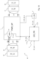
- FIG. 1A shows a block diagram of a power supply system 50 according to a first embodiment of the invention.
- the power supply system 50 comprises a power supply circuit 1, a first battery 40, a first load 45, a second battery 41, a second load 46, a current sensor 3 and a protection circuit 2.
- the power supply circuit 1 comprises a first pair of terminals HV+, HV- and a second pair of terminals LV+, LV-.
- the first battery 40 is connected in parallel to the first pair of terminals HV+, HV-.
- the first load 45 is connected in parallel to the first battery 40.
- the second battery 41 is connected in parallel to the second pair of terminals LV+, LV-.
- the second load 46 is connected in parallel to the second battery 41.
- the power supply circuit 1 is for example a direct-direct voltage converter (DC-DC) or (with the appropriate circuit changes) an alternate-direct voltage converter (AC-DC) or direct-alternate voltage converter (DC-AC).
- DC-DC direct-direct voltage converter
- AC-DC alternate-direct voltage converter
- DC-AC direct-alternate voltage converter
- the power supply circuit 1 is subsequently considered to be a DC-DC voltage converter, but the following considerations can be made similarly for other types of power supply circuits.
- the DC-DC converter 1 converts voltage between two levels of different direct current voltage, indicated with first level of direct voltage ⁇ HV (also referred to as “high voltage”) and with second level of direct voltage ⁇ LV (also referred to as “low voltage”).
- the converter DC-DC 1 is bidirectional, i.e., it is able to perform:
- the first battery 40 is a high voltage battery (e.g., 400 V) connected in parallel to the input/output terminals HV+, HV- of the DC-DC converter 1
- the second battery 41 is a low voltage battery (e.g., 12 V) connected in parallel to the input/output terminals LV+, LV- of the DC-DC converter 1
- the first load 45 is a high voltage load (e.g., an electric motor of a vehicle with electric or hybrid electric/thermal propulsion) and the second load 46 is a low voltage load (e.g., the electrical utilities in the electric or hybrid vehicle passenger compartment).
- the DC-DC converter 1 comprises a switch 1-1 having the function of electrically connecting or disconnecting the internal components of the DC-DC converter 1 to/from the first terminal HV+ connected to the high voltage battery 40.
- the switch 1-1 has the function of electrically connecting/disconnecting the DC-DC converter 1 to/from the high voltage battery 40, as a function of the value of a first switching signal S1_sw, by connecting/disconnecting the internal components of the DC-DC converter 1 to/from the first terminal HV+.
- the DC-DC converter 1 comprises a further switch 1-2 (see Figure 1B ) having the function of electrically connecting or disconnecting the internal components of the DC-DC converter 1 to/from the low voltage terminal LV+ connected to the low voltage battery 41.
- the further switch 1-2 has the function of electrically connecting/disconnecting the DC-DC converter 1 to/from the low voltage battery 40, as a function of the value of a further switching signal S2_sw, by connecting/disconnecting the internal components of the DC-DC converter 1 to/from the second terminal LV+.
- the current sensor 3 is connected to the DC-DC converter 1 and to the protection circuit 2 and it has the function of detecting the current flowing in input and/or in output to/from the DC-DC converter 1, in particular the current I_HV+ flowing in input and/or in output to/from the first terminal HV+.
- the current sensor 3 comprises an input terminal electrically connected to the DC-DC converter 1 and adapted to receive a current detection signal I_HV_dt_in which depends on the current I_HV+ at the input of the first terminal HV+.
- the current sensor 3 further comprises an output terminal electrically connected to the protection circuit 2 and adapted to generate a current measurement signal S1_ms (voltage or current type) representative of the measurement of the current I_HV+ flowing in input to the first terminal HV+ of the DC-DC converter 1.
- S1_ms voltage or current type
- the current sensor 3 is implemented for example with an operating amplifier circuit.
- current sensor 3 is shown externally to the DC-DC converter 1, but the current sensor 3 may also be integrated therein.
- the protection circuit 2 has the function of detecting a sudden variation over time of the current I_HV+ flowing in input and/or in output to/from the first terminal HV+ of the DC-DC converter 1, so as to detect the presence of a sudden variation in the input and/or output current I_HV+ and disconnect the DC-DC converter 1 from the side where the sudden variation in current has been detected, so as to avoid damaging the DC-DC converter 1.
- the DC-DC converter 1 can remain disconnected from the side where the sudden variation in current has been detected for a certain period of time and is then automatically connected again to the same side; in this case the time interval during which the DC-DC converter 1 remains disconnected is used to identify and resolve the cause of the sudden variation in current, without however any guarantee that the fault has actually been resolved.
- the DC-DC converter 1 remains disconnected until the cause of the sudden variation in current at the input or at the ouput of the DC-DC converter 1 has actually been resolved.
- the term "sudden variation" over time of the input current I_HV+ or I_LV+ means that its trend at a given moment has a high slope (that is, an overly rapid variation in the input current), such as a rising or falling edge of the input current I_HV+ or I_LV+.
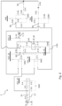
- the protection circuit 2 is shown in greater detail.
- the protection circuit 2 comprises an input terminal I1_IN adapted to receive (from the current sensor 3) the current measurement signal S1_ms representative of the measurement of the current I_HV+ at the input of the first voltage terminal HV+ of the DC-DC converter 1.
- the protection circuit 2 further comprises a differentiator 2-1 configured to measure the slope of the current I_HV+ flowing in input to the first terminal HV+ of the DC-DC converter 1 and configured to detect if the value of the measured slope is greater than or less than a threshold value; in particular, said measurement of the slope of the input current I_HV+ is carried out by means of a differentiation operation of the current measurement signal S1_ms generated by the current sensor 3.
- a differentiator 2-1 configured to measure the slope of the current I_HV+ flowing in input to the first terminal HV+ of the DC-DC converter 1 and configured to detect if the value of the measured slope is greater than or less than a threshold value; in particular, said measurement of the slope of the input current I_HV+ is carried out by means of a differentiation operation of the current measurement signal S1_ms generated by the current sensor 3.
- the protection circuit 2 comprises an output terminal I1_O adapted to generate a disconnection signal S1_dsn having a first value (e.g., a high logic value) representative of an electrical disconnection of the power supply circuit 1 from the battery 40 and having a second value (e.g., a low logic value) representative of an electrical connection of the power supply circuit 1 to the battery 40.
- a first value e.g., a high logic value
- a second value e.g., a low logic value
- the disconnection signal S1_dsn is received at the control terminal of a switch 1-1 inside the DC-DC converter 1, which alternatively connects the DC-DC converter 1 to the high voltage battery 40 by means of the first terminal HV+ or disconnects the DC-DC converter 1 from the high voltage battery 40.
- the DC-DC converter 1 is electrically disconnected from the first battery 40 by disconnecting the internal components of the DC-DC converter 1 from the first terminal HV+, in order to avoid damaging the DC-DC converter 1;
- the electrical connection of the DC-DC converter 1 to the first battery 40 is maintained by means of the connection of the internal components of the DC-DC converter 1 to the first terminal HV+.
- the differentiator 2-1 is an RC circuit, i.e., it comprises a capacitor 2-2 connected in series to a resistor 2-3.
- the capacitor 2-2 has a first terminal connected to the input terminal I1_IN of the protection circuit 2 (and thus the first terminal of the capacitor 2-2 is connected to the output terminal of the current sensor 3) and the resistor 2-3 has a first terminal connected to a second terminal of the capacitor 2-2.
- the protection circuit 2 further comprises a voltage divider having the function of shifting the central voltage, so as to allow sudden variations to be detected in both directions of the power supply circuit 1, i.e., both sudden variations in the current at the input of the first terminal HV+ and exiting from the first terminal HV+, and sudden variations in the current at the input of the second terminal LV+ and exiting from the second terminal LV+.
- the voltage divider comprises a resistor 2-4 connected between the second terminal of the resistor 2-3 and a first reference voltage VCC_33 (e.g., equal to 3.3 V) and comprises a resistor 2-5 connected between the second terminal of the resistor 2-3 and a low reference voltage GND lower than the first reference voltage VCC33 (e.g., the low reference voltage GND is the ground reference voltage).
- VCC_33 e.g., equal to 3.3 V
- GND lower than the first reference voltage VCC33
- the voltage divider is configured to generate a divided voltage on the second terminal of the resistor 2-3, equal for example to 1.65 Volts, in case the voltage divider is supplied by the first reference voltage VDC_33 equal to 3.3 Volts.
- the protection circuit 2 further comprises a capacitor 2-6 connected between the node N1 which is common to the capacitor 2-3 and the resistor 2-3 and the ground reference voltage.
- the protection circuit 2 further comprises a driving stage interposed between the node N1 which is common to the capacitor 2-3 and the resistor 2-3 and the output terminal I1_O of the protection circuit 2.
- the driving stage has the function of detecting the presence of a sudden variation in the current at the input of the DC-DC converter 1 in both directions, i.e., both a sudden variation from the current I_HV+ at the input of the first terminal HV+ and exiting from the first terminal HV+ when the DC-DC converter 1 operates in buck mode, and a sudden variation from the current I_LV+ at the input of the second terminal LV+ and exiting from the second terminal LV+ when the DC-DC converter 1 operates in boost mode.
- the driving stage comprises a first comparator 2-10, a second comparator 2-11, a resistor 2-12, a resistor 2-18, a resistor 2-22, a capacitor 2-21, a resistor 2-26, a capacitor 2-25, a resistor 2-20, a resistor 2-24, a resistor 2-23, a resistor 2-32, a MOSFET transistor 2-30, a resistor 2-31 and a Zener diode 2-35, which are connected together as shown in Fig.2 .
- the set of the first comparator 2-10, of the second comparator 2-11 and of the resistor 2-12 have the function of determining the voltage value on the node N5 which is in common in output from the first and the second comparators 2-10, 2-11.
- the first comparator 2-10 is powered by the first supply voltage VCC_33, it comprises two input terminals (a positive and a negative terminal) and an output terminal and it operates as a voltage comparator, i.e., the first comparator 2-10 generates at the output terminal a high logic value when the voltage value of the positive input terminal is greater than the voltage value of the negative input terminal, while the first comparator 2-10 generates at the output terminal a low logic value when the voltage value of the positive input terminal is less than the voltage value of the negative input terminal.
- the second comparator 2-11 has an operation analogous to that of the first comparator 2-10, i.e., the second comparator 2-11 generates at the output terminal a high logic value when the voltage value of the positive input terminal is greater than the voltage value of the negative input terminal, while the second comparator 2-11 generates at the output terminal a low logic value when the voltage value of the positive input terminal is less than the voltage value of the negative input terminal.
- the comparators 2-10, 2-11 are implemented with respective integrated circuits, such as the integrated circuits identified with LM339, LM239, LM139, LM2901 sold by Texas Instruments.
- the driving stage further comprises:
- the set of the capacitor 2-21, resistor 2-22, capacitor 2-25, resistor 2-26, resistor 2-20, resistor 2-24, resistor 2-23, resistor 2-32, MOSFET transistor 2-30, resistor 2-31 and Zener diode 2-35, have the function of determining the levels of intervention of the protection against sudden variations in the current at the input/output of the power supply circuit 1 and the threshold values of the hysteresis which avoids oscillations between the activation and the deactivation of the protection circuit 2, thus reducing the probability of oscillations between the disconnection of the power supply circuit and the connection of the power supply circuit.
- the positive terminal of the second comparator 2-11 is connected to the negative terminal of the first comparator 2-10 and it is also connected to the node N1 which is common to the capacitor 2-2 and to the first resistor 2-3.
- the positive terminal of the first comparator 2-10 is connected to a node N3 which is common to the first terminal of the capacitor 2-25, to the first terminal of the resistor 2-26, to the first terminal of the resistor 2-24 and to the first terminal of the resistor 2-32.
- the negative terminal of the second comparator 2-11 is connected to a node N2 which is common to the first terminal of the capacitor 2-21, to the first terminal of the resistor 2-22, to the first terminal of the resistor 2-20 and to the first terminal of the resistor 2-23.
- the resistor 2-12 is connected between the output terminal of the first comparator 2-10 and the first supply voltage VCC_33.
- the series connection (of the resistor 2-23 and of the switch 2-30) is connected in parallel to the first parallel connection (of the capacitor 2-21 and of the resistor 2-22), i.e.:
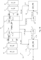
- FIG. 1B shows a block diagram of a power supply system 150 based on a second embodiment of the invention.
- the second embodiment of Figure 1B differs from the first embodiment of Figure 1A in that it comprises a further protection circuit 102, a further current sensor 103 and a further switch 1-2 in the DC-DC converter 101, in order to further detect the current I_LV+ flowing in input and/or in output to/from the second terminal LV+.
- Figure 1B shows two different protection circuits 2, 102, but the invention can also be made using a single protection circuit which performs both the protection functions of the circuits 2 and 102.
- the current sensor 103 of the second embodiment of Figure 1B has a function analogous to the current sensor 3 of the first embodiment of Figure 1A , with the difference that the current sensor 103 has the function of detecting the current I_LV+ flowing in input and/or in output to/from the second terminal LV+, thereby generating a further current measurement signal S2_ms (voltage or current type) representative of the measurement of the current I_LV+ flowing in input to the second terminal LV+.
- the protection circuit 102 of the second embodiment of Figure 1B has a function analogous to the protection circuit 2 of the first embodiment of Figure 1A , with the difference that the protection circuit 102 has the function of detecting a sudden variation over time of the current I_LV+ flowing in input and/or in output to/from the second terminal LV+.
- switch 1-2 has the function of electrically connecting or disconnecting the internal components of the DC-DC converter 1 to/from the second terminal HV+ connected to the low voltage battery 41.
- the foregoing considerations relating to the first terminal HV+ may also be made analogous to the second terminal LV+, i.e., the input terminal I2_IN of the protection circuit 102 is adapted to receive a further current measurement signal S2_ms representative of the measurement of the current I_LV+ at the input of the second terminal LV+ of the DC-DC converter 1.
- the differentiator 2-1 of the protection circuit 102 is configured to measure the slope of the current I_LV+ at the input of the second terminal LV+ of the DC-DC converter 1 and it is configured to detect if the measured slope value is greater or less than a further threshold value.
- the protection circuit 102 comprises an output terminal I2 _ O adapted to generate a further disconnection signal S2_dsn having a first value (e.g., a high logic value) representative of an electrical disconnection of the power supply circuit 1 from the battery 41 and having a second value (e.g., a low logic value) representative of an electrical connection of the power supply circuit 1 to the battery 41.
- a first value e.g., a high logic value
- S2_dsn having a second value (e.g., a low logic value) representative of an electrical connection of the power supply circuit 1 to the battery 41.
- the DC-DC converter 1 is electrically disconnected from the second battery 41 by disconnecting the internal components of the DC-DC converter 1 from the input terminal LV+, in order to avoid damaging the DC-DC converter 1;
- a non-rapid (i.e., gradual) variation in the slope of the current I_LV+ at the input of the terminal LV+ of the DC-DC converter 1 is detected (by means of the sensor 103 and the protection circuit 102), the electrical connection of the DC-DC converter 1 to the second battery 41 is maintained by means of the connection of the internal components of the DC-DC converter 1 to the input terminal LV+.
- the protection circuit 2 further comprises an enable stage 2-50 having the function of enabling or disabling the operation of the protection circuit 2, as a function of the value of an enable signal S_en, which is generated by an external control unit (e.g., a microprocessor),
- an external control unit e.g., a microprocessor
- the enable stage 2-50 is interposed between the driving stage of the protection circuit 2 and the output terminal I1_O of the protection circuit 2.
- the enable stage 2-50 comprises a switch 2-14, a resistor 2-13, a resistor 2-15, a switch 2-40, a resistor 2-16, and a resistor 2-17.
- the switch 2-14 is interposed between the terminal which is common to the output of the first and second comparators 2-10, 2-11 and the output terminal I1_O of the protection circuit 2; in addition, the switch 2-14 comprises a control terminal adapted to control the opening and closing of the switch 2-14.
- the control terminal is connected to a terminal which is common to the resistors 2-13 and 2-15.
- the switch 2-14 is implemented for example with a MOSFET transistor.
- the resistor 2-13 is connected between the terminal which is common to the output of the first and second comparators 2-10, 2-11 and the control terminal of the switch 2-14.
- the resistor 2-15 is connected between the control terminal of the switch 2-14 and the switch 2-40.
- the switch 2-40 is connected between the resistor 2-15 and the resistors 2-16, 2-17.
- the resistor 2-16 is connected between the switch 2-40 and the first reference voltage VCC_33.
- the resistor 2-17 is connected between the switch 2-40 and the low reference voltage GND.
- the switch 2-40 comprises a first, a second and a third terminal and comprises a control terminal adapted to receive the enable signal S_en in order to connect, alternatively, the first terminal to the second or to the third terminal.
- the switch 2-40 is such to switch between the following two possible positions, as a function of the value of the enable signal S_en:
- the DC-DC converter 1 is automatically reconnected after a defined time interval ⁇ T following the instant of detection of sudden variation in the current at the input of the first input terminal HV+ of the DC-DC converter 1; the defined time interval ⁇ T is calculated for example by means of a time counter inside the protection circuit 2.
- the input current I_HV+ has a gradually increasing trend from a value I1 to a value I2, thus the disconnection signal S1_dsn has a low logic value V_L (for example, equal to 0 Volts) that maintains the DC-DC converter 1 connected to the high voltage battery 40 by means of the first input terminal HV+.
- V_L for example, equal to 0 Volts
- the voltage V_N1 of the node N1 has a positive peak in the instants comprised between t1 and t2, with a maximum value Vmax greater than the minimum value Vmin.
- the DC-DC converter 1 is automatically reconnected to the high voltage battery 40, which is assumed to no longer be affected by the fault.
Landscapes
- Engineering & Computer Science (AREA)
- Power Engineering (AREA)
- Mechanical Engineering (AREA)
- Physics & Mathematics (AREA)
- General Physics & Mathematics (AREA)
- Life Sciences & Earth Sciences (AREA)
- Sustainable Development (AREA)
- Sustainable Energy (AREA)
- Transportation (AREA)
- Dc-Dc Converters (AREA)
- Emergency Protection Circuit Devices (AREA)
- Amplifiers (AREA)
Claims (10)
- Système d'alimentation électrique (50), comprenant :- un circuit d'alimentation électrique (1) comportant une borne (HV+) présentant un niveau de tension (ΔHV) ;- un capteur de courant (3) adapté pour générer un signal de mesure de courant (S1_ms) représentatif de la mesure du courant (I_HV+) circulant à travers la borne du circuit d'alimentation électrique ;- un circuit de protection (2) comprenant :• une borne d'entrée (I1_IN) adaptée pour recevoir le signal de mesure de courant (S1_ms) représentatif de la mesure du courant circulant à travers ladite borne du circuit d'alimentation électrique ;caractérisé en ce que le circuit de protection comprend de plus :• un différentiateur (2-1 ; 2-2, 2-3) adapté pour mesurer la pente du signal de mesure du courant ;• un étage de pilotage (2-10, 2-12, 2-11, 2-20, 2-21, 2-22, 2-23, 2-30, 2-24, 2-25, 2-26, 2-31, 2-32, 2-35) interposé entre le différentiateur et la borne de sortie du circuit de protection, l'étage de pilotage étant adapté pour générer un signal de déconnexion (S1_dsn) transportant :• une première valeur représentative du branchement électrique des composants internes du circuit d'alimentation électrique à sa borne (HV+), dans le cas où la valeur mesurée de la pente du signal de courant circulant à travers ladite borne du circuit d'alimentation électrique est inférieure ou égale à une valeur seuil ; ou• une deuxième valeur représentative du débranchement électrique des composants internes du circuit d'alimentation électrique de sa borne (HV+), dans le cas où la valeur mesurée de la pente du signal de courant circulant à travers ladite borne du circuit d'alimentation électrique est supérieure à la valeur seuil ;• une borne de sortie (I1_O) adaptée pour générer le signal de déconnexion (S1_dsn) ;dans lequel le circuit d'alimentation électrique (1) est configuré pour recevoir le signal de déconnexion (S1_dsn) et, alternativement, pour brancher électriquement ses composants internes à sa borne ou pour débrancher électriquement ses composants internes de sa borne, en fonction de la valeur du signal de déconnexion (S1_dsn).
- Système d'alimentation électrique selon la revendication 1, dans lequel le différentiateur comprend un branchement en série d'un premier condensateur (2-2) et d'une première résistance (2-3), dans lequel :- la borne d'entrée (I1_IN) du circuit de protection est branchée à une première borne du premier condensateur (2-2) ;- l'entrée de l'étage de pilotage est branchée à un nœud (N1) étant commun au premier condensateur (2-2) et à la première résistance (2-3).
- Système d'alimentation électrique selon la revendication 2, dans lequel :- le premier condensateur (2-2) comporte une première borne branchée à la borne d'entrée (I1_IN) du circuit de protection ;- la première résistance (2-3) comporte une première borne branchée à une deuxième borne (N1) du premier condensateur ;le circuit de protection comprend de plus un diviseur de tension (2-4, 2-5) configuré pour générer une tension divisée sur une deuxième borne de la première résistance (2-3) ;et dans lequel l'étage de pilotage est interposé entre un nœud (N1) étant commun à la deuxième borne du premier condensateur, à la première borne de la première résistance, au nœud de tension divisée et à la borne de sortie (I1_O) du circuit de protection.
- Système d'alimentation électrique selon la revendication 3, dans lequel le diviseur de tension comprend :- une deuxième résistance (2-4) branchée entre la deuxième borne de la première résistance (2-3) et une première tension d'alimentation (VCC33) ;- une troisième résistance (2-5) branchée entre la deuxième borne de la première résistance (2-3) et une tension de référence basse (GND) étant inférieure à la première tension d'alimentation.
- Système d'alimentation électrique selon l'une quelconque des revendications précédentes, dans lequel le circuit d'alimentation électrique (1) comprend un interrupteur (1-1) configuré pour brancher/débrancher électriquement les composants internes du circuit d'alimentation à sa/à partir de sa borne d'entrée (HV+), l'interrupteur (1-1) comprenant une borne de contrôle (S1_sw) adaptée pour recevoir le signal de déconnexion (S1_dsn) généré par le circuit de protection,
dans lequel l'interrupteur est configuré pour :- brancher électriquement les composants internes du circuit d'alimentation à sa borne d'entrée (HV+), dans le cas où le signal de déconnexion (S1_dsn) achemine la première valeur représentative du branchement électrique ;- débrancher électriquement les composants internes du circuit d'alimentation de sa borne (HV+), si le signal de déconnexion (S1_dsn) achemine la deuxième valeur représentative du débranchement électrique. - Système d'alimentation électrique selon l'une quelconque des revendications 3 à 5, comprenant de plus :- un premier comparateur (2-10) et un deuxième comparateur (2-11) comprenant une borne d'entrée positive respective, une borne d'entrée négative respective et une borne de sortie respective adaptées pour générer un signal respectif de comparaison entre la valeur du signal des bornes d'entrée positive et négative, les premier et deuxième comparateurs étant alimentés par une première tension d'alimentation (VCC_33) ;- une quatrième résistance (2-12) ;- un premier branchement en parallèle d'un deuxième condensateur (2-21) et d'une cinquième résistance (2-22) ;- un deuxième branchement en parallèle d'un troisième condensateur (2-25) et d'une sixième résistance (2-26) ;- une septième résistance (2-20) branchée entre le premier branchement en parallèle et une tension de référence (Vref) ;- une huitième résistance (2-24) branchée entre la tension de référence (Vref) et le deuxième branchement en parallèle ;- une neuvième résistance (2-23) interposée entre le premier branchement en parallèle et un nœud commun (N4) ;- une dixième résistance (2-32) interposée entre le deuxième branchement en parallèle et le nœud commun (N4) ;- un branchement en série d'une onzième résistance (2-23) et d'un deuxième interrupteur (2-30), ledit deuxième interrupteur (2-30) comprenant une borne de contrôle branchée au nœud commun (N4) et adaptée pour contrôler l'ouverture et la fermeture du deuxième interrupteur (2-30) ;- une douzième résistance (2-31) branchée entre la borne de contrôle du deuxième interrupteur (2-30) et le nœud commun (N4) ; dans lequel :- la borne d'entrée négative du premier comparateur (2-10) est branchée à la borne d'entrée positive du deuxième comparateur et au nœud (N1) étant commun au premier condensateur (2-2) et à la première résistance (2-3) ;- la borne positive du premier comparateur est branchée au deuxième branchement en parallèle (2-25, 2-26) ;- la borne négative du deuxième comparateur (2-11) est branchée au premier branchement en parallèle (2-21, 2-22) ;- la borne de sortie du premier comparateur (2-10) est branchée à la borne de sortie du deuxième comparateur ;- la borne de sortie (I1_O) du circuit de protection est associée au nœud (N5) étant commun aux bornes de sortie des premier et deuxième comparateurs ;- la quatrième résistance (2-12) est branchée entre le nœud (N5) étant commun aux bornes de sortie des premier et deuxième comparateurs et la première tension d'alimentation (VCC_33) ;- ledit branchement en série est branché en parallèle au premier branchement en parallèle.
- Système d'alimentation électrique selon la revendication 6, comprenant de plus un étage d'activation (2-50) interposé entre l'étage de pilotage et la borne de sortie (I1_O) du circuit de protection, l'étage d'activation étant configuré pour activer ou désactiver le fonctionnement du circuit de protection (2), en fonction de la valeur d'un signal d'activation (S_en),l'étage d'activation comprenant :- un troisième interrupteur (2-14) branché entre le nœud (N5) étant commun aux bornes de sortie des premier et deuxième comparateurs et la borne de sortie (I1_O) du circuit de protection, le troisième interrupteur comprenant une borne de contrôle pour contrôler l'ouverture et la fermeture du troisième interrupteur ;- une onzième résistance (2-13) branchée entre le nœud (N5) étant commun aux bornes de sortie des premier et deuxième comparateurs et la borne de contrôle du troisième interrupteur (2-14) ;- un interrupteur (2-40) comprenant une première, une deuxième et une troisième borne et comprenant une borne de contrôle adaptée pour recevoir le signal d'activation (S_en) pour brancher, alternativement, la première borne à la deuxième ou à la troisième borne, en fonction de la valeur du signal d'activation ;- une douzième résistance (2-15) branchée entre la borne de contrôle du troisième interrupteur (2-14) et la première borne de l'interrupteur (2-40) ;- une treizième résistance (2-16) branchée entre la deuxième borne de l'interrupteur et la première tension d'alimentation (VCC_33) ;- une quatorzième résistance (2-17) branchée entre la troisième borne de l'interrupteur et une tension de référence basse (GND) ;le système comprenant de plus une unité de contrôle configurée pour générer le signal d'activation (S_en) afin d'activer ou de désactiver le fonctionnement du circuit de protection.
- Système d'alimentation électrique selon l'une quelconque des revendications précédentes, comprenant de plus une quinzième résistance (2-18) branchée entre la borne de sortie (I1_O) du circuit de protection et une deuxième tension d'alimentation (VCC_5) étant supérieure à la première tension d'alimentation.
- Système d'alimentation électrique selon l'une quelconque des revendications précédentes, dans lequel le circuit d'alimentation électrique est un convertisseur de tension CC-CC de type bidirectionnel configuré pour convertir ledit niveau de tension de type courant continu haute tension (ΔHV) en un niveau de courant continu basse tension (ΔLV), et vice versa, le convertisseur comprenant une première paire de bornes d'entrée/sortie adaptées pour recevoir/générer le niveau de courant continu haute tension (HV+, HV-) et comprenant une deuxième paire de bornes d'entrée/sortie adaptées pour recevoir/générer le niveau de courant continu basse tension (LV+, LV-), le système comprenant de plus :- une batterie haute tension (40) branchée en parallèle à la première paire de bornes d'entrée/sortie ;- une charge électrique haute tension (45) branchée en parallèle à la batterie haute tension (40) ;- une batterie basse tension (41) branchée en parallèle à la deuxième paire de bornes d'entrée/sortie ;- une charge électrique basse tension (46) branchée en parallèle à la batterie basse tension (41).
- Véhicule électrique ou hybride à moteur électrique et moteur à combustion interne, comprenant un système d'alimentation électrique selon l'une quelconque des revendications précédentes.
Applications Claiming Priority (2)
| Application Number | Priority Date | Filing Date | Title |
|---|---|---|---|
| IT102019000013065A IT201900013065A1 (it) | 2019-07-26 | 2019-07-26 | Sistema di alimentazione con protezione da variazioni di corrente |
| PCT/IB2020/057011 WO2021019399A1 (fr) | 2019-07-26 | 2020-07-24 | Système d'alimentation électrique avec protection contre les variations de courant |
Publications (2)
| Publication Number | Publication Date |
|---|---|
| EP4005053A1 EP4005053A1 (fr) | 2022-06-01 |
| EP4005053B1 true EP4005053B1 (fr) | 2025-04-16 |
Family
ID=68807241
Family Applications (1)
| Application Number | Title | Priority Date | Filing Date |
|---|---|---|---|
| EP20757668.7A Active EP4005053B1 (fr) | 2019-07-26 | 2020-07-24 | Système d'alimentation électrique avec protection contre les variations de courant |
Country Status (5)
| Country | Link |
|---|---|
| US (1) | US12021372B2 (fr) |
| EP (1) | EP4005053B1 (fr) |
| CN (1) | CN114521314B (fr) |
| IT (1) | IT201900013065A1 (fr) |
| WO (1) | WO2021019399A1 (fr) |
Families Citing this family (3)
| Publication number | Priority date | Publication date | Assignee | Title |
|---|---|---|---|---|
| CN115902350B (zh) * | 2022-11-21 | 2026-04-07 | 驭新智能底盘系统(湖北)有限公司 | 一种电压检测装置 |
| JP2024159606A (ja) * | 2023-04-28 | 2024-11-08 | リテルフューズ、インコーポレイテッド | スロープ検出に基づく過電流保護 |
| US12413065B2 (en) * | 2023-06-26 | 2025-09-09 | Lennox Industries Inc. | Motor disconnection detection while the motor is switched on |
Family Cites Families (22)
| Publication number | Priority date | Publication date | Assignee | Title |
|---|---|---|---|---|
| BE795784A (fr) * | 1972-02-22 | 1973-06-18 | Taylor Servomex Ltd | Appareil pour la mesure des courants faibles |
| JP2841531B2 (ja) * | 1988-10-24 | 1998-12-24 | 富士電機株式会社 | 電力変換器のアーム短絡検知回路 |
| DE4111831A1 (de) * | 1991-04-11 | 1992-10-15 | Abb Patent Gmbh | Verfahren zur ausloesung eines elektrischen schalters sowie vorrichtung zur durchfuehrung des verfahrens |
| JPH11215689A (ja) * | 1998-01-28 | 1999-08-06 | Canon Inc | 過電流保護装置 |
| JP2002010474A (ja) * | 2000-06-20 | 2002-01-11 | Fujitsu General Ltd | 電源保護装置 |
| US7432613B2 (en) * | 2005-01-21 | 2008-10-07 | C.E. Niehoff & Co. | Self-protective high-current low-loss bi-directional semiconductor switch module and method of operation |
| US7616461B2 (en) * | 2007-01-12 | 2009-11-10 | System General Corp. | Control method and circuit with indirect input voltage detection by switching current slope detection |
| US7719812B2 (en) * | 2007-05-15 | 2010-05-18 | Astec International Limited | Power converters with rate of change monitoring for fault prediction and/or detection |
| CN201234120Y (zh) * | 2008-07-29 | 2009-05-06 | 吉增权 | 新型煤电钻综合保护装置 |
| US8558712B2 (en) * | 2010-06-03 | 2013-10-15 | C&C Power, Inc. | Battery system and management method |
| KR101118375B1 (ko) * | 2010-09-07 | 2012-03-09 | 엘에스산전 주식회사 | 전력계통에서의 고속 사고판단 장치 |
| US20130027817A1 (en) * | 2011-07-25 | 2013-01-31 | General Electric Company | Micro electro-mechanical switch (mems) based over current motor protection system |
| KR101438041B1 (ko) * | 2013-03-13 | 2014-09-04 | 엘에스산전 주식회사 | 전력회로 개폐기용 제어 회로 |
| JP6268870B2 (ja) * | 2013-09-27 | 2018-01-31 | 日産自動車株式会社 | 車両用電源供給装置 |
| US9728955B2 (en) * | 2013-12-11 | 2017-08-08 | General Electric Company | Zone selective interlocking (ZSI) power distribution operating a ZSI power distribution system |
| US10461522B2 (en) * | 2015-02-13 | 2019-10-29 | Mitsubishi Electric Corporation | Protection device and protection system |
| JP6455205B2 (ja) * | 2015-02-13 | 2019-01-23 | トヨタ自動車株式会社 | 昇圧制御装置 |
| US9806617B1 (en) * | 2016-09-09 | 2017-10-31 | Dialog Semiconductor (Uk) Limited | Switch mode power converter with overshoot and undershoot transient control circuits |
| JP6729321B2 (ja) * | 2016-11-22 | 2020-07-22 | トヨタ自動車株式会社 | ハイブリッド自動車 |
| KR102033548B1 (ko) * | 2017-08-10 | 2019-11-08 | 주식회사 경신 | 양방향 dc-dc 컨버터의 보호 장치 및 방법 |
| CN109586242B (zh) * | 2017-09-29 | 2020-03-10 | 昆山国显光电有限公司 | 电路保护方法、保护电路和电路保护装置 |
| CN109672147B (zh) * | 2019-02-19 | 2019-09-24 | 国电南瑞科技股份有限公司 | 一种晶闸管电流源型变流电路的快速电流保护方法 |
-
2019
- 2019-07-26 IT IT102019000013065A patent/IT201900013065A1/it unknown
-
2020
- 2020-07-24 WO PCT/IB2020/057011 patent/WO2021019399A1/fr not_active Ceased
- 2020-07-24 CN CN202080067837.1A patent/CN114521314B/zh active Active
- 2020-07-24 US US17/597,832 patent/US12021372B2/en active Active
- 2020-07-24 EP EP20757668.7A patent/EP4005053B1/fr active Active
Also Published As
| Publication number | Publication date |
|---|---|
| CN114521314B (zh) | 2025-12-23 |
| IT201900013065A1 (it) | 2021-01-26 |
| CN114521314A (zh) | 2022-05-20 |
| EP4005053A1 (fr) | 2022-06-01 |
| WO2021019399A1 (fr) | 2021-02-04 |
| US20220278524A1 (en) | 2022-09-01 |
| US12021372B2 (en) | 2024-06-25 |
Similar Documents
| Publication | Publication Date | Title |
|---|---|---|
| US11135932B2 (en) | Electric charging control device | |
| US10855100B2 (en) | Power supply control apparatus and battery unit | |
| EP3246196B1 (fr) | Pistolet de charge et procédé de charge de véhicule électrique | |
| US8487629B2 (en) | Battery system, electric vehicle, and battery control apparatus | |
| US8829717B2 (en) | Battery control device and battery system | |
| EP4005053B1 (fr) | Système d'alimentation électrique avec protection contre les variations de courant | |
| US9696380B2 (en) | Relay control system and method for controlling same | |
| CN105270295B (zh) | 用于机动车辆的车载电气系统 | |
| US10207587B2 (en) | Pre-charging switch arrangement, power supplying arrangement and method for connecting a load to a high direct-current voltage source | |
| US8929113B2 (en) | Capacitor discharger for power conversion system | |
| US20180115178A1 (en) | Battery management system and method of controlling the same | |
| US20150314740A1 (en) | Method For The Controlled Connection Of A Plurality Of On-Board Power System Branches Of A Vehicle, Control Unit For Carrying Out The Method And On-Board Power System | |
| CN102470811B (zh) | 车辆的车载电源以及用于车载电源的控制设备 | |
| JP6877912B2 (ja) | 組電池監視システム | |
| CN107870284A (zh) | 电压检测装置 | |
| CN104521089B (zh) | 蓄电池系统和具有蓄电池系统的机动车 | |
| US20240201242A1 (en) | Device for monitoring a power distributor of a motor vehicle | |
| JP7064392B2 (ja) | 電池監視装置、電池監視システム、および電池監視方法 | |
| CN115441530A (zh) | 控制装置和包括该控制装置的载具电力分配架构 | |
| JP2018021880A (ja) | 電圧監視装置および組電池監視システム | |
| US20030011248A1 (en) | Error recognition device for a multi-voltage vehicle electrical system | |
| JP2016174475A (ja) | 蓄電システム | |
| JP2025503240A (ja) | 充電ステーション側の過電圧保護措置を考慮したモニタリングを伴う充電方法 | |
| US11345240B2 (en) | Electrical on-board network device for supply of at least two electrical loads in a motor vehicle, and motor vehicle, switching device, and method for operating an on-board network device | |
| KR20120037973A (ko) | 차량용 발전 전압 제어 장치 |
Legal Events
| Date | Code | Title | Description |
|---|---|---|---|
| STAA | Information on the status of an ep patent application or granted ep patent |
Free format text: STATUS: UNKNOWN |
|
| STAA | Information on the status of an ep patent application or granted ep patent |
Free format text: STATUS: THE INTERNATIONAL PUBLICATION HAS BEEN MADE |
|
| PUAI | Public reference made under article 153(3) epc to a published international application that has entered the european phase |
Free format text: ORIGINAL CODE: 0009012 |
|
| STAA | Information on the status of an ep patent application or granted ep patent |
Free format text: STATUS: REQUEST FOR EXAMINATION WAS MADE |
|
| 17P | Request for examination filed |
Effective date: 20220127 |
|
| AK | Designated contracting states |
Kind code of ref document: A1 Designated state(s): AL AT BE BG CH CY CZ DE DK EE ES FI FR GB GR HR HU IE IS IT LI LT LU LV MC MK MT NL NO PL PT RO RS SE SI SK SM TR |
|
| DAV | Request for validation of the european patent (deleted) | ||
| DAX | Request for extension of the european patent (deleted) | ||
| GRAP | Despatch of communication of intention to grant a patent |
Free format text: ORIGINAL CODE: EPIDOSNIGR1 |
|
| STAA | Information on the status of an ep patent application or granted ep patent |
Free format text: STATUS: GRANT OF PATENT IS INTENDED |
|
| INTG | Intention to grant announced |
Effective date: 20240524 |
|
| GRAS | Grant fee paid |
Free format text: ORIGINAL CODE: EPIDOSNIGR3 |
|
| GRAA | (expected) grant |
Free format text: ORIGINAL CODE: 0009210 |
|
| STAA | Information on the status of an ep patent application or granted ep patent |
Free format text: STATUS: THE PATENT HAS BEEN GRANTED |
|
| AK | Designated contracting states |
Kind code of ref document: B1 Designated state(s): AL AT BE BG CH CY CZ DE DK EE ES FI FR GB GR HR HU IE IS IT LI LT LU LV MC MK MT NL NO PL PT RO RS SE SI SK SM TR |
|
| REG | Reference to a national code |
Ref country code: GB Ref legal event code: FG4D |
|
| REG | Reference to a national code |
Ref country code: CH Ref legal event code: EP Ref country code: DE Ref legal event code: R096 Ref document number: 602020049565 Country of ref document: DE |
|
| REG | Reference to a national code |
Ref country code: IE Ref legal event code: FG4D |
|
| REG | Reference to a national code |
Ref country code: NL Ref legal event code: MP Effective date: 20250416 |
|
| PG25 | Lapsed in a contracting state [announced via postgrant information from national office to epo] |
Ref country code: NL Free format text: LAPSE BECAUSE OF FAILURE TO SUBMIT A TRANSLATION OF THE DESCRIPTION OR TO PAY THE FEE WITHIN THE PRESCRIBED TIME-LIMIT Effective date: 20250416 |
|
| REG | Reference to a national code |
Ref country code: AT Ref legal event code: MK05 Ref document number: 1786480 Country of ref document: AT Kind code of ref document: T Effective date: 20250416 |
|
| PG25 | Lapsed in a contracting state [announced via postgrant information from national office to epo] |
Ref country code: FI Free format text: LAPSE BECAUSE OF FAILURE TO SUBMIT A TRANSLATION OF THE DESCRIPTION OR TO PAY THE FEE WITHIN THE PRESCRIBED TIME-LIMIT Effective date: 20250416 Ref country code: ES Free format text: LAPSE BECAUSE OF FAILURE TO SUBMIT A TRANSLATION OF THE DESCRIPTION OR TO PAY THE FEE WITHIN THE PRESCRIBED TIME-LIMIT Effective date: 20250416 Ref country code: PT Free format text: LAPSE BECAUSE OF FAILURE TO SUBMIT A TRANSLATION OF THE DESCRIPTION OR TO PAY THE FEE WITHIN THE PRESCRIBED TIME-LIMIT Effective date: 20250818 |
|
| PGFP | Annual fee paid to national office [announced via postgrant information from national office to epo] |
Ref country code: DE Payment date: 20250728 Year of fee payment: 6 |
|
| REG | Reference to a national code |
Ref country code: LT Ref legal event code: MG9D |
|
| PG25 | Lapsed in a contracting state [announced via postgrant information from national office to epo] |
Ref country code: NO Free format text: LAPSE BECAUSE OF FAILURE TO SUBMIT A TRANSLATION OF THE DESCRIPTION OR TO PAY THE FEE WITHIN THE PRESCRIBED TIME-LIMIT Effective date: 20250716 Ref country code: GR Free format text: LAPSE BECAUSE OF FAILURE TO SUBMIT A TRANSLATION OF THE DESCRIPTION OR TO PAY THE FEE WITHIN THE PRESCRIBED TIME-LIMIT Effective date: 20250717 |
|
| PG25 | Lapsed in a contracting state [announced via postgrant information from national office to epo] |
Ref country code: PL Free format text: LAPSE BECAUSE OF FAILURE TO SUBMIT A TRANSLATION OF THE DESCRIPTION OR TO PAY THE FEE WITHIN THE PRESCRIBED TIME-LIMIT Effective date: 20250416 |
|
| PGFP | Annual fee paid to national office [announced via postgrant information from national office to epo] |
Ref country code: IT Payment date: 20250728 Year of fee payment: 6 |
|
| PG25 | Lapsed in a contracting state [announced via postgrant information from national office to epo] |
Ref country code: BG Free format text: LAPSE BECAUSE OF FAILURE TO SUBMIT A TRANSLATION OF THE DESCRIPTION OR TO PAY THE FEE WITHIN THE PRESCRIBED TIME-LIMIT Effective date: 20250416 |
|
| PG25 | Lapsed in a contracting state [announced via postgrant information from national office to epo] |
Ref country code: HR Free format text: LAPSE BECAUSE OF FAILURE TO SUBMIT A TRANSLATION OF THE DESCRIPTION OR TO PAY THE FEE WITHIN THE PRESCRIBED TIME-LIMIT Effective date: 20250416 |
|
| PG25 | Lapsed in a contracting state [announced via postgrant information from national office to epo] |
Ref country code: AT Free format text: LAPSE BECAUSE OF FAILURE TO SUBMIT A TRANSLATION OF THE DESCRIPTION OR TO PAY THE FEE WITHIN THE PRESCRIBED TIME-LIMIT Effective date: 20250416 |
|
| PG25 | Lapsed in a contracting state [announced via postgrant information from national office to epo] |
Ref country code: RS Free format text: LAPSE BECAUSE OF FAILURE TO SUBMIT A TRANSLATION OF THE DESCRIPTION OR TO PAY THE FEE WITHIN THE PRESCRIBED TIME-LIMIT Effective date: 20250716 |
|
| PG25 | Lapsed in a contracting state [announced via postgrant information from national office to epo] |
Ref country code: IS Free format text: LAPSE BECAUSE OF FAILURE TO SUBMIT A TRANSLATION OF THE DESCRIPTION OR TO PAY THE FEE WITHIN THE PRESCRIBED TIME-LIMIT Effective date: 20250816 |
|
| PG25 | Lapsed in a contracting state [announced via postgrant information from national office to epo] |
Ref country code: LV Free format text: LAPSE BECAUSE OF FAILURE TO SUBMIT A TRANSLATION OF THE DESCRIPTION OR TO PAY THE FEE WITHIN THE PRESCRIBED TIME-LIMIT Effective date: 20250416 |
|
| PG25 | Lapsed in a contracting state [announced via postgrant information from national office to epo] |
Ref country code: SM Free format text: LAPSE BECAUSE OF FAILURE TO SUBMIT A TRANSLATION OF THE DESCRIPTION OR TO PAY THE FEE WITHIN THE PRESCRIBED TIME-LIMIT Effective date: 20250416 Ref country code: DK Free format text: LAPSE BECAUSE OF FAILURE TO SUBMIT A TRANSLATION OF THE DESCRIPTION OR TO PAY THE FEE WITHIN THE PRESCRIBED TIME-LIMIT Effective date: 20250416 |
|
| REG | Reference to a national code |
Ref country code: DE Ref legal event code: R097 Ref document number: 602020049565 Country of ref document: DE |
|
| PG25 | Lapsed in a contracting state [announced via postgrant information from national office to epo] |
Ref country code: CZ Free format text: LAPSE BECAUSE OF FAILURE TO SUBMIT A TRANSLATION OF THE DESCRIPTION OR TO PAY THE FEE WITHIN THE PRESCRIBED TIME-LIMIT Effective date: 20250416 |
|
| PG25 | Lapsed in a contracting state [announced via postgrant information from national office to epo] |
Ref country code: EE Free format text: LAPSE BECAUSE OF FAILURE TO SUBMIT A TRANSLATION OF THE DESCRIPTION OR TO PAY THE FEE WITHIN THE PRESCRIBED TIME-LIMIT Effective date: 20250416 |
|
| PG25 | Lapsed in a contracting state [announced via postgrant information from national office to epo] |
Ref country code: SK Free format text: LAPSE BECAUSE OF FAILURE TO SUBMIT A TRANSLATION OF THE DESCRIPTION OR TO PAY THE FEE WITHIN THE PRESCRIBED TIME-LIMIT Effective date: 20250416 Ref country code: RO Free format text: LAPSE BECAUSE OF FAILURE TO SUBMIT A TRANSLATION OF THE DESCRIPTION OR TO PAY THE FEE WITHIN THE PRESCRIBED TIME-LIMIT Effective date: 20250416 |
|
| PLBE | No opposition filed within time limit |
Free format text: ORIGINAL CODE: 0009261 |
|
| STAA | Information on the status of an ep patent application or granted ep patent |
Free format text: STATUS: NO OPPOSITION FILED WITHIN TIME LIMIT |
|
| REG | Reference to a national code |
Ref country code: CH Ref legal event code: H13 Free format text: ST27 STATUS EVENT CODE: U-0-0-H10-H13 (AS PROVIDED BY THE NATIONAL OFFICE) Effective date: 20260224 |
|
| REG | Reference to a national code |
Ref country code: CH Ref legal event code: L10 Free format text: ST27 STATUS EVENT CODE: U-0-0-L10-L00 (AS PROVIDED BY THE NATIONAL OFFICE) Effective date: 20260225 |
|
| PG25 | Lapsed in a contracting state [announced via postgrant information from national office to epo] |
Ref country code: LU Free format text: LAPSE BECAUSE OF NON-PAYMENT OF DUE FEES Effective date: 20250724 |
|
| 26N | No opposition filed |
Effective date: 20260119 |
|
| GBPC | Gb: european patent ceased through non-payment of renewal fee |
Effective date: 20250724 |
|
| REG | Reference to a national code |
Ref country code: BE Ref legal event code: MM Effective date: 20250731 |
|
| PG25 | Lapsed in a contracting state [announced via postgrant information from national office to epo] |
Ref country code: GB Free format text: LAPSE BECAUSE OF NON-PAYMENT OF DUE FEES Effective date: 20250724 |
|
| PG25 | Lapsed in a contracting state [announced via postgrant information from national office to epo] |
Ref country code: BE Free format text: LAPSE BECAUSE OF NON-PAYMENT OF DUE FEES Effective date: 20250731 |
|
| PG25 | Lapsed in a contracting state [announced via postgrant information from national office to epo] |
Ref country code: FR Free format text: LAPSE BECAUSE OF NON-PAYMENT OF DUE FEES Effective date: 20250731 |
|
| PG25 | Lapsed in a contracting state [announced via postgrant information from national office to epo] |
Ref country code: CH Free format text: LAPSE BECAUSE OF NON-PAYMENT OF DUE FEES Effective date: 20250731 |