EP4005098B1 - Verfahren und vorrichtung zur maximierung gleichzeitiger modemoperationen in einem konvergierten kommunikationsgerät - Google Patents
Verfahren und vorrichtung zur maximierung gleichzeitiger modemoperationen in einem konvergierten kommunikationsgerät Download PDFInfo
- Publication number
- EP4005098B1 EP4005098B1 EP20750136.2A EP20750136A EP4005098B1 EP 4005098 B1 EP4005098 B1 EP 4005098B1 EP 20750136 A EP20750136 A EP 20750136A EP 4005098 B1 EP4005098 B1 EP 4005098B1
- Authority
- EP
- European Patent Office
- Prior art keywords
- modem
- interference
- communication device
- cem
- portable communication
- Prior art date
- Legal status (The legal status is an assumption and is not a legal conclusion. Google has not performed a legal analysis and makes no representation as to the accuracy of the status listed.)
- Active
Links
Images

Classifications
-
- H—ELECTRICITY
- H04—ELECTRIC COMMUNICATION TECHNIQUE
- H04B—TRANSMISSION
- H04B1/00—Details of transmission systems, not covered by a single one of groups H04B3/00 - H04B13/00; Details of transmission systems not characterised by the medium used for transmission
- H04B1/38—Transceivers, i.e. devices in which transmitter and receiver form a structural unit and in which at least one part is used for functions of transmitting and receiving
- H04B1/40—Circuits
- H04B1/403—Circuits using the same oscillator for generating both the transmitter frequency and the receiver local oscillator frequency
- H04B1/406—Circuits using the same oscillator for generating both the transmitter frequency and the receiver local oscillator frequency with more than one transmission mode, e.g. analog and digital modes
-
- H—ELECTRICITY
- H04—ELECTRIC COMMUNICATION TECHNIQUE
- H04W—WIRELESS COMMUNICATION NETWORKS
- H04W72/00—Local resource management
- H04W72/50—Allocation or scheduling criteria for wireless resources
- H04W72/54—Allocation or scheduling criteria for wireless resources based on quality criteria
- H04W72/541—Allocation or scheduling criteria for wireless resources based on quality criteria using the level of interference
-
- H—ELECTRICITY
- H04—ELECTRIC COMMUNICATION TECHNIQUE
- H04W—WIRELESS COMMUNICATION NETWORKS
- H04W74/00—Wireless channel access
- H04W74/08—Non-scheduled access, e.g. ALOHA
- H04W74/0808—Non-scheduled access, e.g. ALOHA using carrier sensing, e.g. carrier sense multiple access [CSMA]
- H04W74/0816—Non-scheduled access, e.g. ALOHA using carrier sensing, e.g. carrier sense multiple access [CSMA] with collision avoidance
-
- H—ELECTRICITY
- H04—ELECTRIC COMMUNICATION TECHNIQUE
- H04W—WIRELESS COMMUNICATION NETWORKS
- H04W84/00—Network topologies
- H04W84/02—Hierarchically pre-organised networks, e.g. paging networks, cellular networks, WLAN [Wireless Local Area Network] or WLL [Wireless Local Loop]
- H04W84/04—Large scale networks; Deep hierarchical networks
- H04W84/042—Public Land Mobile systems, e.g. cellular systems
-
- H—ELECTRICITY
- H04—ELECTRIC COMMUNICATION TECHNIQUE
- H04W—WIRELESS COMMUNICATION NETWORKS
- H04W88/00—Devices specially adapted for wireless communication networks, e.g. terminals, base stations or access point devices
- H04W88/02—Terminal devices
- H04W88/06—Terminal devices adapted for operation in multiple networks or having at least two operational modes, e.g. multi-mode terminals
Definitions
- Portable battery powered communication devices are often utilized in public safety environments, such as law enforcement, fire rescue, and the like.
- public safety communication devices may be referred to as converged devices.
- converged devices It is highly desirable that a converged device be able to operate two modems simultaneously.
- operating two modems simultaneously can result in plethora of complex self-interference scenarios not encountered in conventional single modem devices. For example, out-of-band emissions, blocking and/or intermediation occurring in one sub-system of a converged device may severely interfere with the performance of another sub-system of the converged device. Compliance with regulatory emission limits may also lead to inter-modulation artifacts from one modem interference with nearby spectrum of another modem.
- an apparatus and method for dynamically managing simultaneous modem operation in a portable communication device are directed to mitigating interference resulting from the simultaneous operation of the two or more modems.
- Improved converged communications is provided through the use of a programmable logic array operating as a coexistence module (CEM) interoperating with a plurality of different processors, a plurality of different modems, and a plurality of attenuation switches.
- CEM coexistence module
- Interference during converged operation is detected, analyzed, and applicable mitigation is applied to the interference, thereby enabling converged communications to be established in a mitigated mode.
- the mitigated mode of operation continues until the interference has been removed.
- Mission critical communications is maintained without relying on the use of infrastructure collaboration.
- FIG. 1 is a block diagram of a portable communication device 100 formed and operating in accordance with some embodiments.
- the portable communication device 100 is powered by a battery (not shown).
- the portable communication device 100 comprises a programmable logic array operating as a coexistence module (CEM) 102, an applications processor (AP) 104 operatively coupled to the CEM 102, and a baseband processor (BP) 106 operatively coupled to the CEM and the AP.
- the portable communication device 100 further comprise a first modem 108, such as a land mobile radio (LMR) modem, operatively coupled to the BP 106, the first modem operating using a first frequency band of operation.
- LMR land mobile radio
- the first modem is responsible for mission critical operations, such as scan, push-to-talk (PTT), and high power audio.
- the portable communication device 100 further comprises a second modem 110, such as a long term evolution (LTE) modem, operatively coupled to the AP 104, the second modem operating using a second frequency band of operation.
- LTE long term evolution
- the AP 104 is responsible for non-mission critical operations, such as software applications associated with touchscreen interface, low power audio, and global positioning system (GPS).
- Other radio elements such as radio frequency (RF) transmitters, receivers, power amplifiers are not shown (to maintain simplicity) but are understood to be embodied within the device 100.
- the indicator signals 118, 120, 122 are analyzed by the CEM 102 and the AP 104 for interference.
- the CEM drives a hardware attenuation enable line 126 to both the AP 104 and the attenuation switch 112, thereby engaging the attenuation switch 112 which serves to disconnect the second modem 110 from the second antenna 132.
- the AP 104 performs additional analysis to confirm the interference detected by the CEM 102. In some embodiments, a change in the indicator signals 118,120, 122 will trigger this interference analysis. The AP 104 then determines and performs an appropriate interference mitigation.
- LMR and LTE modems While examples are provided which refer to LMR and LTE modems, it is to be appreciated that the embodiments can be applied beyond LMR and LTE operations.
- the use of the baseband processor 106 and the LMR modem 108 is particularly advantageous to public safety communication devices which support mission critical communications. Such devices rely on mission critical push-to-talk (PTT) and scan, hence the mitigation of interference from the LTE modem 110 is extremely important.
- the applications processor 104 and the LTE modem 110 provide a plurality of non-mission critical features such as text-to-speech, touch screen display features, BLUETOOTH, WiFi, and/or global positioning system (GPS) to name a few.
- GPS global positioning system
- the portable communication device 100 when operating using LMR and LTE frequency bands controlled by LMR and LTE modems is able to detect and mitigate interference generated by: LTE transmit frequency bands conflicting with LMR receive bands, external LMR transmissions interfering with the LTE modem, internal LMR transmissions interfering with LTE modem, and LTE transmit frequency bands interfering with internally generated LMR transmissions.
- the mitigation approach comprises reducing power, and/or band steering, and/ or reducing data speed to the second modem in the manner described previously.
- Examples of potential interference may include but are not limited to, the upper edge of LMR 700 MHz band (769MHz - 775 MHz) which may be very close to the lower edge of LTE BAND 13 (Uplink 777MHz - 787MHz) resulting in out of band emissions interference when two transceivers are operating simultaneously.
- Another example, in which frequencies overlap are LMR 800 MHz band (862MHz - 869 MHz) and LTE BAND 5 (Downlink 869 MHz - 894 MHz).
- the hardware mitigation provided by the CEM 102 to engage the attenuation switch 112 provides instantaneous interference protection while the software mitigation is executed. These software mitigations can take hundreds of milliseconds to enact, and relying on them without the hardware mitigation would result in degraded LMR scan and mobility operations.
- the coexistence module (CEM) 102 takes into account the currently active first and second modems and automatically applies respective mitigation only as needed under the predetermined scenarios of concern.
- Portable communication device 100 advantageously allows for fine adjustment of predetermined modem transceiver parameters such as power level and band operation.
- Implementation of the CEM 102 and attenuation switch 112 in hardware advantageously avoids substantial delays that would be experienced through a software only mitigation approach. In many cases, the dynamically changing nature of the communications protocol makes a software implementation impractical or unrealizable.
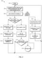
- FIG. 2 is a flowchart of a method 200 for managing simultaneous modem operations in a portable communication device, such as the converged portable communication device 100 of FIG. 1 , in accordance with some embodiments.
- the method 200 has been illustrated in terms of LMR and LTE frequency bands, controlled by separate modems for ease of description, however it is to be appreciated that the method 200 is applicable to other modems operating simultaneously in frequency bands susceptible to interference.
- the method begins at 202, with simultaneous operation of first and second modems, such as first and second modems 108, 110, respectively operating on first and second frequency bands.
- simultaneous LMR and LTE communications taking place using LMR and LTE modems 108, 110 respectively, in a coexistence mode of the portable communication device 100.
- a change in frequency band operation takes place at 204, for example a change in either LTE band operation and/or LMR TX/RX and/or LMR band operation
- the method ensures operation of the first frequency band communications (LMR band) remains normal.
- a check is made for detecting interference during the coexistence mode. For example, the method detects whether the LTE band operations have interfered with the LMR band operations.
- the method 200 proceeds by engaging an attenuation switch 112 to the antenna path of the second modem at 210 to temporarily negate second frequency band communications at 212.
- the attenuation switch 112 can be used to temporarily negate LTE communications, while the LMR modem which may be handling mission critical communications operates normally.
- the cause of interference is analyzed, by the applications processor 104 and a determination is made as to whether a mitigation action is possible.
- the cause of interference may be analyzed by the AP and CEM of FIG. 1 as previously described.
- the method 200 proceeds to a mitigation mode at 216.
- the mitigation may be a software controlled mitigation comprising for example, reduced power to the second modem and/or reduced data speed to the second modem (the LTE modem) as determined at 218.
- the software mitigation 218 may incorporate an optional holdoff timer as previously described to cater for LMR scan and mobility operations.
- the method 200 proceeds by disengaging the attenuation switch at 220 and establishing communications using the applicable software mitigation thereby re-establishing coexistence operations at 222.
- the LTE modem may operate at restricted power and/or speed while the LMR operations remain normal. Communications continue in the mitigated coexistence mode returning to 204 to await a frequency change or change in TX/RX state.
- the method 200 returns back to 204 to await a frequency change or change in LMR TX/RX state.
- the first frequency band communication such as the LMR communication
- the second frequency band communication such as LTE communications
- the attenuation switch is disengaged at 230.
- the removal of software mitigation 232 may incorporate an optional holdoff timer as previously described to cater for LMR scan and mobility operations. Any previously applied software mitigation is removed at 232, thereby allowing the second frequency band operations, such as the LTE band communications, to return to normal, non-mitigated operation at 234, while returning to 204 to await changes in frequency change or change in LMR TX/RX state..
- the method and apparatus provided herein have beneficially enabled coexistence by mitigating interference without infrastructure interaction.
- the method and apparatus advantageously allow for fine adjustment for specific transceiver parameters such as power level, data throttling, and band steering.
- the mitigation approach advantageously focus on band edges and avoids the use of large filters that could result in increased insertion loss across the band, as well as the cost and size associated with such filters. Additionally, the mitigation approach avoids the use of a software-only approach that can take hundreds of milliseconds which would degrade LMR scan/mobility operations that can be on the order of 50ms.
- the embodiments can be applied to communication devices having more than two processors supported more than two modems operating with nearby frequency bands that are susceptible to RF interference. As such the embodiments can be said to apply to a plurality of different modems supporting communication protocols operating over different but nearby frequency bands which are susceptible to interference with each other.
- a includes ...a
- or “contains ...a” does not, without more constraints, preclude the existence of additional identical elements in the process, method, article, or apparatus that comprises, has, includes, contains the element.
- the terms “a” and “an” are defined as one or more unless explicitly stated otherwise herein.
- the terms “substantially,” “essentially,” “approximately,” “about” or any other version thereof, are defined as being close to as understood by one of ordinary skill in the art, and in one non-limiting embodiment the term is defined to be within 10%, in another embodiment within 5%, in another embodiment within 1% and in another embodiment within 0.5%.
- the term “coupled” as used herein is defined as connected, although not necessarily directly and not necessarily mechanically.
- a device or structure that is “configured” in a certain way is configured in at least that way, but may also be configured in ways that are not listed.
- processors such as microprocessors, digital signal processors, customized processors and field programmable gate arrays (FPGAs) and unique stored program instructions (including both software and firmware) that control the one or more processors to implement, in conjunction with certain non-processor circuits, some, most, or all of the functions of the method and/or apparatus described herein.
- processors or “processing devices”
- FPGAs field programmable gate arrays
- unique stored program instructions including both software and firmware
Landscapes
- Engineering & Computer Science (AREA)
- Computer Networks & Wireless Communication (AREA)
- Signal Processing (AREA)
- Quality & Reliability (AREA)
- Mobile Radio Communication Systems (AREA)
- Transceivers (AREA)
Claims (15)
- Tragbare Kommunikationsvorrichtung (100), die Folgendes umfasst:ein programmierbares Logikarray für den Betrieb als Koexistenzmodul, CEM, (102);einen Anwendungsprozessor, AP, (104), der operativ mit dem CEM (102) gekoppelt ist;einen Basisbandprozessor, BP, (106), der operativ mit dem CEM (102) gekoppelt ist;ein erstes Modem (108), das operativ mit dem BP gekoppelt ist, wobei das erste Modem (108) dazu ausgelegt ist, unter Verwendung eines ersten Frequenzbandes zu arbeiten;ein zweites Modem (110), das operativ mit dem AP (104) gekoppelt ist, wobei das zweite Modem (110) dazu ausgelegt ist, unter Verwendung eines zweiten Frequenzbandes zu arbeiten;wobei der AP (104), der BP (106) und das erste und das zweite Modem (108, 110) dazu ausgelegt sind, in einem konvergenten Modus zu arbeiten, in dem sowohl das erste als auch das zweite Modem (108, 110) gleichzeitig arbeiten;einen Dämpfungsschalter (112), der operativ mit dem CEM (102) und dem zweiten Modem (110) gekoppelt ist;wobei der BP dazu ausgelegt ist, Signale an das CEM (102) und an den AP (104) zu erzeugen, während das erste Modem (108) auf dem ersten Frequenzband sendet und empfängt;das zweite Modem (110) dazu ausgelegt ist, Signale an das CEM (102) und an den AP (104) zu erzeugen, wenn das zweite Modem (110) auf dem zweiten Frequenzband sendet und empfängt; undder AP (104) und das CEM (102) dazu ausgelegt sind, Signale zu detektieren, die Störung zwischen dem ersten und dem zweiten Frequenzband anzeigen, und eine Störungsursache als eine aus einer Mehrzahl von vorbestimmten Störungsszenarien zu bestimmen,das CEM (102) dazu ausgelegt ist, den Dämpfungsschalter (112) zu aktivieren, um vorübergehend einen Antennenpfad des zweiten Modems (110) zu trennen und HF-Kommunikationen zu negieren, die mit dem zweiten Modem (110) assoziiert sind,wobei, während der AP (104) dazu ausgelegt ist, eine anwendbare Störungsabschwächung zu bestimmen, um der Störung entgegenzuwirken, der AP (104) dazu ausgelegt ist,die Störungsabschwächung anzuwenden, um dem zweiten Modem (110) zu ermöglichen, in einem eingeschränkten Modus zu arbeiten; undder AP (104) dazu ausgelegt ist, ein Deaktivierungssignal an das CEM (102) zu erzeugen, und das CEM (102) dazu ausgelegt ist, den Dämpfungsschalter (112) in Reaktion darauf zu deaktivieren, wodurch ein konvergenter Betrieb wiederhergestellt wird, während dessen das erste Modem (108) und das zweite Modem (110) gleichzeitig arbeiten, wobei das zweite Modem (110) in dem eingeschränkten Modus arbeitet.
- Tragbare Kommunikationsvorrichtung (100) nach Anspruch 1, wobei das CEM (102) dazu ausgelegt ist, eine Entfernung der Störung zu detektieren und den AP (104) anzuweisen, die Störungsabschwächung zu deaktivieren, wodurch das erste und das zweite Modem (108, 110) in einen regulären konvergenten Betrieb zurückversetzt werden.
- Tragbare Kommunikationsvorrichtung (100) nach Anspruch 1, wobei das erste Kommunikationsfrequenzband ein konfigurierbares Frequenzband ist.
- Tragbare Kommunikationsvorrichtung (100) nach Anspruch 1, die ferner Folgendes umfasst:eine erste Antenne, die mit dem ersten Modem (108) assoziiert ist; undeine zweite Antenne, die mit dem zweiten Modem (110) assoziiert ist;einen HF-Detektor, der operativ zwischen die zweite Antenne, das zweite Modem (110) und das CEM (102) gekoppelt ist, wobei der HF-Detektor zum Detektieren einer HF-Energie dient, die mit dem ersten Kommunikationsfrequenzband assoziiert ist, an der zweiten Antenne vorhanden ist und einen vorbestimmten HF-Energieschwellenwert überschreitet; undwobei das CEM dazu ausgelegt ist, den Dämpfungsschalter (112) zu aktivieren, während detektiert wird, dass die HF-Energie den vorbestimmten HF-Energieschwellenwert überschreitet,wobei die HF-Energie optional durch mindestens eines von Folgenden verursacht wird:interne Übertragungen, die das zweite Modem (110) stören;externe Übertragungen, die das zweite Modem (110) stören.
- Tragbare Kommunikationsvorrichtung (100) nach Anspruch 1, wobei das erste und das zweite Modem (108, 110) Kommunikationsprotokolle unterstützen, die über Frequenzbänder arbeiten, die für gegenseitige Störung anfällig sind.
- Tragbare Kommunikationsvorrichtung (100) nach Anspruch 1, wobei der BP (106) und das erste Modem dazu ausgelegt sind, unternehmenskritische LMR-Kommunikationen für öffentliche Sicherheit zu verwalten, und der AP (104) und das zweite Modem (110) dazu ausgelegt sind, nicht unternehmenskritische LTE-Kommunikationen zu verwalten.
- Verfahren zum Verwalten von Kommunikationen in einer konvergenten tragbaren Kommunikationsvorrichtung, wobei das Verfahren Folgendes umfasst:Betreiben eines programmierbaren Logikarrays als Koexistenzmodul, CEM, (102) der konvergenten tragbaren Kommunikationsvorrichtung, gleichzeitiges Betreiben eines ersten und eines zweiten Modems (108, 110) über ein erstes und ein zweites Frequenzband in einem regulären konvergenten Betriebsmodus der tragbaren Kommunikationsvorrichtung;Detektieren von HF-Störung während des konvergenten Betriebsmodus;Aktivieren eines Dämpfungsschalters (112) zu dem zweiten Modem (110), um einen Antennenpfad des zweiten Modems vorübergehend zu trennen und HF-Kommunikationen zu negieren, die mit dem zweiten Modem (110) assoziiert sind;Bestimmen einer Störungsursache als eine aus einer Mehrzahl von vorbestimmten Störungsszenarien;Bestimmen, ob eine Abschwächungsmaßnahme anwendbar ist, basierend auf der bestimmten Störungsursache;Anwenden der Abschwächungsmaßnahme, um einen abgeschwächten konvergenten Betriebsmodus einzurichten;Deaktivieren des Dämpfungsschalters (112) bei Einrichtung des abgeschwächten konvergenten Betriebsmodus; undKommunizieren unter Verwendung des abgeschwächten konvergenten Betriebsmodus.
- Verfahren nach Anspruch 7, das ferner Folgendes umfasst:Detektieren der Entfernung der HF-Störung; undDeaktivieren der Störungsabschwächung, wodurch das erste und das zweite Modem (108, 110) in einen regulären konvergenten Betrieb zurückversetzt werden.
- Verfahren nach Anspruch 7, wobei der Dämpfungsschalter (112) durch Folgendes gesteuert wird:
ein Logikarray, das als Koexistenzmodul arbeitet, wobei das Logikarray auf Folgendes reagiert: einen Basisbandprozessor, der mit dem ersten Modem (108) assoziiert ist, einen Anwendungsprozessor, der mit dem zweiten Modem (110) assoziiert ist, und eine externe Leistungsdetektionsschaltung. - Tragbare Kommunikationsvorrichtung (100) nach Anspruch 1 oder Verfahren nach Anspruch 7, wobei das Anwenden der Abschwächungsmaßnahme mindestens eines von Folgendem umfasst:Anwenden einer reduzierten Leistung auf das zweite Modem (110);Anwenden einer Datengeschwindigkeitsdrosselung auf das zweite Modem (110);Anwenden von Bandsteuerung des zweiten Modems (110).
- Tragbare Kommunikationsvorrichtung (100) nach Anspruch 1 oder Verfahren nach Anspruch 7, wobei die Störung mindestens eines von Folgendem umfasst:Sendefrequenzbänder des zweiten Modems (110) kollidieren mit Empfangsbändern des ersten Modems (108);externe HF-Energie stört das zweite Modem (110);interne Übertragungen des ersten Modems (108) stören das zweite Modem (110);Sendefrequenzbänder des zweiten Modems (110) stören intern erzeugte Übertragungen des ersten Modems (108).
- Tragbare Kommunikationsvorrichtung (100) nach Anspruch 1 oder Verfahren nach Anspruch 7, wobei das Anwenden der Abschwächung ferner Folgendes umfasst:Warten, bis ein konfigurierbarer Sperrzeitgeber abläuft; undÜberprüfen, ob die Störung noch vorhanden ist, bevor die Störungsabschwächung angewendet wird.
- Tragbare Kommunikationsvorrichtung (100) nach Anspruch 2 oder Verfahren nach Anspruch 8, wobei das Detektieren der Entfernung der Störung ferner Folgendes umfasst:Warten, bis ein konfigurierbarer Sperrzeitgeber abläuft; undÜberprüfen, ob die Störung noch immer nicht vorhanden ist, bevor die Störungsabschwächung deaktiviert wird.
- Tragbare Kommunikationsvorrichtung (100) nach Anspruch 1 oder Verfahren nach Anspruch 7, wobei das erste Modem (108) ein Landmobilfunk-Modem, LMR-Modem, ist, das dazu ausgelegt ist, über ein LMR-Frequenzband zu arbeiten, und das zweite Modem (110) ein Long Term Evolution-Modem, LTE-Modem, ist, das dazu ausgelegt ist, über ein LTE-Frequenzband zu arbeiten.
- Tragbare Kommunikationsvorrichtung (100) oder Verfahren nach Anspruch 14, wobei das LMR-Modem während der Abschwächung voll betriebsfähig bleibt.
Applications Claiming Priority (2)
| Application Number | Priority Date | Filing Date | Title |
|---|---|---|---|
| US16/525,864 US10917899B1 (en) | 2019-07-30 | 2019-07-30 | Method and apparatus to maximize simultaneous modem operations in a converged communication device |
| PCT/US2020/042242 WO2021021450A1 (en) | 2019-07-30 | 2020-07-16 | Method and apparatus to maximize simultaneous modem operations in a converged communication device |
Publications (3)
| Publication Number | Publication Date |
|---|---|
| EP4005098A1 EP4005098A1 (de) | 2022-06-01 |
| EP4005098B1 true EP4005098B1 (de) | 2025-07-02 |
| EP4005098C0 EP4005098C0 (de) | 2025-07-02 |
Family
ID=71895305
Family Applications (1)
| Application Number | Title | Priority Date | Filing Date |
|---|---|---|---|
| EP20750136.2A Active EP4005098B1 (de) | 2019-07-30 | 2020-07-16 | Verfahren und vorrichtung zur maximierung gleichzeitiger modemoperationen in einem konvergierten kommunikationsgerät |
Country Status (5)
| Country | Link |
|---|---|
| US (1) | US10917899B1 (de) |
| EP (1) | EP4005098B1 (de) |
| AU (1) | AU2020319606B2 (de) |
| CA (1) | CA3148053C (de) |
| WO (1) | WO2021021450A1 (de) |
Families Citing this family (3)
| Publication number | Priority date | Publication date | Assignee | Title |
|---|---|---|---|---|
| US11304215B2 (en) * | 2019-07-30 | 2022-04-12 | Motorola Solutions, Inc. | Methods and apparatus for a portable communication device |
| US11690023B2 (en) | 2021-08-30 | 2023-06-27 | Motorola Solutions, Inc. | Interference mitigation for portable communication device |
| CN115361035B (zh) * | 2022-08-15 | 2023-11-10 | Oppo广东移动通信有限公司 | 射频系统、通信设备、通信控制方法及通信控制装置 |
Family Cites Families (39)
| Publication number | Priority date | Publication date | Assignee | Title |
|---|---|---|---|---|
| US6643522B1 (en) | 2000-03-27 | 2003-11-04 | Sharp Laboratories Of America, Inc. | Method and apparatus providing simultaneous dual mode operations for radios in the shared spectrum |
| US7197291B2 (en) | 2003-10-03 | 2007-03-27 | Motorola, Inc. | Multimode receiver and method for controlling signal interference |
| US20090245221A1 (en) * | 2008-03-31 | 2009-10-01 | Nokia Corporation | Multiradio operation using interference reporting |
| US8085834B2 (en) * | 2008-04-30 | 2011-12-27 | Infineon Technologies Ag | System partitioning for multi-mobile devices |
| US20110105037A1 (en) * | 2009-10-30 | 2011-05-05 | Qualcomm Incorporated | Methods and systems for interference cancellation in multi-mode coexistence modems |
| US9277564B2 (en) * | 2010-08-05 | 2016-03-01 | Qualcomm Incorporated | Method and apparatus to facilitate support for multi-radio coexistence |
| GB2489702A (en) | 2011-04-04 | 2012-10-10 | Nec Corp | Determining interference between first and second radio technologies in a mobile communications device |
| US8923816B2 (en) * | 2011-07-28 | 2014-12-30 | Samsung Electronics Co., Ltd. | Apparatus and method for providing seamless service between a cellular network and wireless local area network for a mobile user |
| FR2979045B1 (fr) | 2011-08-09 | 2013-09-20 | Cassidian | Procede de coexistence radioelectrique entre deux dispositifs pmr dont l'un est en bande etroite et l'autre a large bande |
| US8995918B2 (en) | 2011-11-14 | 2015-03-31 | Motorola Solutions, Inc. | Mitigating transmission interference between digital radio and broadband communication devices |
| US9066363B2 (en) | 2011-12-29 | 2015-06-23 | Motorola Solutions, Inc. | Methods and apparatus for mitigating interference between co-located collaborating radios |
| US10264587B2 (en) | 2012-01-17 | 2019-04-16 | Motorola Solutions, Inc. | Collaborative interference mitigation between physically-proximate narrowband and broadband communication devices |
| US8712331B2 (en) * | 2012-04-13 | 2014-04-29 | Motorola Solutions, Inc. | Methods and apparatus for mitigating interference between co-located collaborating radios |
| US9008020B2 (en) | 2012-08-31 | 2015-04-14 | Motorola Solutions, Inc. | Method and apparatus for managing resources in a wireless communication system implementing multiple air interface technologies |
| GB2507800B (en) * | 2012-11-12 | 2015-05-06 | Broadcom Corp | Apparatus and method |
| US9980171B2 (en) * | 2013-03-14 | 2018-05-22 | Liveu Ltd. | Apparatus for cooperating with a mobile device |
| US9252863B2 (en) * | 2013-04-04 | 2016-02-02 | Mbit Wireless, Inc. | Method and apparatus for adaptive antenna sharing |
| CN104185183A (zh) | 2013-05-20 | 2014-12-03 | 中兴通讯股份有限公司 | 一种实现d2d通信的方法及系统 |
| WO2014189436A2 (en) * | 2013-05-23 | 2014-11-27 | Telefonaktiebolaget L M Ericsson (Publ) | Methods and apparatus for handling connections to multiple radio access technologies |
| US10834649B2 (en) * | 2013-05-30 | 2020-11-10 | Telefonaktiebolaget Lm Ericsson (Publ) | RAN-controlled selective handover between first and second RAN:S |
| CN104469818B (zh) * | 2013-09-18 | 2018-11-13 | 华为终端有限公司 | 避免信道干扰的电路、方法以及相关装置 |
| US9231711B2 (en) | 2013-11-22 | 2016-01-05 | Harris Corporation | Interference management service for portable communication devices |
| US20150163752A1 (en) * | 2013-12-10 | 2015-06-11 | Samsung Electronics Co., Ltd. | Method and apparatus for mitigating interference in user equipment |
| US10135139B2 (en) | 2014-07-10 | 2018-11-20 | Motorola Solutions, Inc. | Multiband antenna system |
| US9247413B1 (en) | 2014-10-17 | 2016-01-26 | Motorola Solutions, Inc. | Method and apparatus for flexible fast network switching |
| US9749263B2 (en) | 2014-11-05 | 2017-08-29 | Motorola Solutions, Inc. | Methods and systems for identifying and reducing LTE-system coverage holes due to external interference |
| US9504058B2 (en) | 2014-12-18 | 2016-11-22 | Motorola Solutions, Inc. | Methods and systems for scheduling transmission of uplink communication |
| US9363845B1 (en) | 2014-12-31 | 2016-06-07 | Motorola Solutions, Inc. | Apparatus and method for carrier aggregation and fast network switching with a single-baseband-modem, carrier-aggregation-capable wireless-communication device |
| US9642154B2 (en) | 2015-01-29 | 2017-05-02 | Motorola Solutions, Inc. | Uplink broadband scheduling in the presence of narrowband interference |
| US10034202B2 (en) * | 2015-05-15 | 2018-07-24 | Mediatek Inc. | Finer control of WLAN association for network-controlled LTE-WLAN internetworking |
| US10122406B2 (en) * | 2015-06-29 | 2018-11-06 | Qualcomm Incorporated | Coexistence over a shared band with dual antenna sharing |
| US9668300B2 (en) | 2015-08-28 | 2017-05-30 | Motorola Solutions, Inc. | Filtering apparatus and method for multiband radio |
| US9615299B1 (en) | 2015-09-30 | 2017-04-04 | Motorola Solutions, Inc. | Method and apparatus for mitigating interference between mobile devices in a wireless communication system |
| US9461696B1 (en) | 2015-10-05 | 2016-10-04 | Motorola Solutions, Inc. | Method and converged communication device for enhancing broadband and narrowband communication |
| US10178688B2 (en) * | 2015-10-06 | 2019-01-08 | Motorola Solutions, Inc. | Method of scheduling short uplink transmissions |
| US10334473B2 (en) | 2015-12-15 | 2019-06-25 | Motorola Solutions, Inc. | Systems and methods for reducing radiofrequency interference in a mobile communications device |
| US9979069B2 (en) | 2016-05-02 | 2018-05-22 | Motorola Solutions, Inc. | Wireless broadband/land mobile radio antenna system |
| US10420023B2 (en) | 2018-01-10 | 2019-09-17 | Dell Products, Lp | Method and apparatus for multiple radio access technology antenna front end controller integration |
| CN108183725B (zh) | 2018-01-17 | 2021-02-26 | Oppo广东移动通信有限公司 | 天线共存互扰处理方法、装置、存储介质及电子设备 |
-
2019
- 2019-07-30 US US16/525,864 patent/US10917899B1/en active Active
-
2020
- 2020-07-16 WO PCT/US2020/042242 patent/WO2021021450A1/en not_active Ceased
- 2020-07-16 AU AU2020319606A patent/AU2020319606B2/en active Active
- 2020-07-16 EP EP20750136.2A patent/EP4005098B1/de active Active
- 2020-07-16 CA CA3148053A patent/CA3148053C/en active Active
Also Published As
| Publication number | Publication date |
|---|---|
| US10917899B1 (en) | 2021-02-09 |
| AU2020319606A1 (en) | 2022-02-17 |
| US20210037536A1 (en) | 2021-02-04 |
| WO2021021450A1 (en) | 2021-02-04 |
| CA3148053C (en) | 2023-12-05 |
| EP4005098A1 (de) | 2022-06-01 |
| AU2020319606B2 (en) | 2023-02-23 |
| CA3148053A1 (en) | 2021-02-04 |
| EP4005098C0 (de) | 2025-07-02 |
Similar Documents
| Publication | Publication Date | Title |
|---|---|---|
| EP3255938B1 (de) | Sendeleistungsmodulation zur ermöglichung der vorrichtungsinternen koexistenz zwischen drahtloskommunikationstechnologien | |
| US9781687B2 (en) | Controlling radio transmission power in a multi-radio wireless communication device | |
| US9467236B2 (en) | Method of In-device interference mitigation for cellular, bluetooth, WiFi, and satellite systems coexistence | |
| AU2020319606B2 (en) | Method and apparatus to maximize simultaneous modem operations in a converged communication device | |
| EP1841084B1 (de) | Funkkommunikationsgerät und Funkkommunikationsverfahren | |
| EP2375571B1 (de) | Benutzergerätevorrichtung zur simultanen Übertragung von Signalen über mehrere drahtlose Kommunikationschips, auf die verschiedene drahtlose Kommunikationsschemata angewandt werden, und Verfahren zur Steuerung der Übertragungsleistung dafür | |
| EP3629637B1 (de) | Lte-nr-leistungssteuerung für en-dc | |
| EP1863187A2 (de) | Funkkommunikationsgerät und Funkkommunikationsverfahren | |
| EP2986049B1 (de) | Kanalinterferenzvermeidende schaltung, verfahren und vorrichtung dafür | |
| WO2012064093A2 (en) | Method and apparatus of handling in-device co-existence interference in a multi-radio environment | |
| EP3654623B1 (de) | Verfahren zur reduzierung von strahlung und mobiles endgerät | |
| US9197166B2 (en) | Increasing power amplifier linearity to facilitate in-device coexistence between wireless communication technologies | |
| JP3984906B2 (ja) | Phs無線lanコンボ及びphs無線lan端末 | |
| WO2014100180A1 (en) | Agile active interference cancellation (aaic) for multi-radio mobile devices | |
| EP4396949B1 (de) | Interferenzunterdrückung für eine tragbare kommunikationsvorrichtung | |
| EP2997790B1 (de) | Verfahren für paketübertragungsschutz und kommunikationsvorrichtung damit | |
| EP3577797B1 (de) | Reduzierung der schwingung in einem signalverstärker | |
| US20130194939A1 (en) | Transceiver | |
| CN111629437B (zh) | 远端基站干扰的处理方法及设备 | |
| CA3147873A1 (en) | Method and apparatus for managing broadband data in a converged portable communication device |
Legal Events
| Date | Code | Title | Description |
|---|---|---|---|
| STAA | Information on the status of an ep patent application or granted ep patent |
Free format text: STATUS: UNKNOWN |
|
| STAA | Information on the status of an ep patent application or granted ep patent |
Free format text: STATUS: THE INTERNATIONAL PUBLICATION HAS BEEN MADE |
|
| PUAI | Public reference made under article 153(3) epc to a published international application that has entered the european phase |
Free format text: ORIGINAL CODE: 0009012 |
|
| STAA | Information on the status of an ep patent application or granted ep patent |
Free format text: STATUS: REQUEST FOR EXAMINATION WAS MADE |
|
| 17P | Request for examination filed |
Effective date: 20220128 |
|
| AK | Designated contracting states |
Kind code of ref document: A1 Designated state(s): AL AT BE BG CH CY CZ DE DK EE ES FI FR GB GR HR HU IE IS IT LI LT LU LV MC MK MT NL NO PL PT RO RS SE SI SK SM TR |
|
| DAV | Request for validation of the european patent (deleted) | ||
| DAX | Request for extension of the european patent (deleted) | ||
| STAA | Information on the status of an ep patent application or granted ep patent |
Free format text: STATUS: EXAMINATION IS IN PROGRESS |
|
| 17Q | First examination report despatched |
Effective date: 20240617 |
|
| 17Q | First examination report despatched |
Effective date: 20240625 |
|
| GRAP | Despatch of communication of intention to grant a patent |
Free format text: ORIGINAL CODE: EPIDOSNIGR1 |
|
| STAA | Information on the status of an ep patent application or granted ep patent |
Free format text: STATUS: GRANT OF PATENT IS INTENDED |
|
| INTG | Intention to grant announced |
Effective date: 20250207 |
|
| GRAS | Grant fee paid |
Free format text: ORIGINAL CODE: EPIDOSNIGR3 |
|
| GRAA | (expected) grant |
Free format text: ORIGINAL CODE: 0009210 |
|
| STAA | Information on the status of an ep patent application or granted ep patent |
Free format text: STATUS: THE PATENT HAS BEEN GRANTED |
|
| AK | Designated contracting states |
Kind code of ref document: B1 Designated state(s): AL AT BE BG CH CY CZ DE DK EE ES FI FR GB GR HR HU IE IS IT LI LT LU LV MC MK MT NL NO PL PT RO RS SE SI SK SM TR |
|
| REG | Reference to a national code |
Ref country code: GB Ref legal event code: FG4D |
|
| REG | Reference to a national code |
Ref country code: CH Ref legal event code: EP |
|
| REG | Reference to a national code |
Ref country code: DE Ref legal event code: R096 Ref document number: 602020053820 Country of ref document: DE |
|
| REG | Reference to a national code |
Ref country code: IE Ref legal event code: FG4D |
|
| U01 | Request for unitary effect filed |
Effective date: 20250730 |
|
| U07 | Unitary effect registered |
Designated state(s): AT BE BG DE DK EE FI FR IT LT LU LV MT NL PT RO SE SI Effective date: 20250808 |
|
| U20 | Renewal fee for the european patent with unitary effect paid |
Year of fee payment: 6 Effective date: 20250820 |
|
| PGFP | Annual fee paid to national office [announced via postgrant information from national office to epo] |
Ref country code: GB Payment date: 20250822 Year of fee payment: 6 |
|
| PG25 | Lapsed in a contracting state [announced via postgrant information from national office to epo] |
Ref country code: IS Free format text: LAPSE BECAUSE OF FAILURE TO SUBMIT A TRANSLATION OF THE DESCRIPTION OR TO PAY THE FEE WITHIN THE PRESCRIBED TIME-LIMIT Effective date: 20251102 |
|
| PG25 | Lapsed in a contracting state [announced via postgrant information from national office to epo] |
Ref country code: NO Free format text: LAPSE BECAUSE OF FAILURE TO SUBMIT A TRANSLATION OF THE DESCRIPTION OR TO PAY THE FEE WITHIN THE PRESCRIBED TIME-LIMIT Effective date: 20251002 |
|
| PG25 | Lapsed in a contracting state [announced via postgrant information from national office to epo] |
Ref country code: HR Free format text: LAPSE BECAUSE OF FAILURE TO SUBMIT A TRANSLATION OF THE DESCRIPTION OR TO PAY THE FEE WITHIN THE PRESCRIBED TIME-LIMIT Effective date: 20250702 |
|
| PG25 | Lapsed in a contracting state [announced via postgrant information from national office to epo] |
Ref country code: GR Free format text: LAPSE BECAUSE OF FAILURE TO SUBMIT A TRANSLATION OF THE DESCRIPTION OR TO PAY THE FEE WITHIN THE PRESCRIBED TIME-LIMIT Effective date: 20251003 |
|
| PG25 | Lapsed in a contracting state [announced via postgrant information from national office to epo] |
Ref country code: CZ Free format text: LAPSE BECAUSE OF FAILURE TO SUBMIT A TRANSLATION OF THE DESCRIPTION OR TO PAY THE FEE WITHIN THE PRESCRIBED TIME-LIMIT Effective date: 20250702 |
|
| PG25 | Lapsed in a contracting state [announced via postgrant information from national office to epo] |
Ref country code: PL Free format text: LAPSE BECAUSE OF FAILURE TO SUBMIT A TRANSLATION OF THE DESCRIPTION OR TO PAY THE FEE WITHIN THE PRESCRIBED TIME-LIMIT Effective date: 20250702 |
|
| PG25 | Lapsed in a contracting state [announced via postgrant information from national office to epo] |
Ref country code: RS Free format text: LAPSE BECAUSE OF FAILURE TO SUBMIT A TRANSLATION OF THE DESCRIPTION OR TO PAY THE FEE WITHIN THE PRESCRIBED TIME-LIMIT Effective date: 20251002 |
|
| PG25 | Lapsed in a contracting state [announced via postgrant information from national office to epo] |
Ref country code: ES Free format text: LAPSE BECAUSE OF FAILURE TO SUBMIT A TRANSLATION OF THE DESCRIPTION OR TO PAY THE FEE WITHIN THE PRESCRIBED TIME-LIMIT Effective date: 20250702 |
|
| REG | Reference to a national code |
Ref country code: CH Ref legal event code: H13 Free format text: ST27 STATUS EVENT CODE: U-0-0-H10-H13 (AS PROVIDED BY THE NATIONAL OFFICE) Effective date: 20260224 |
|
| PG25 | Lapsed in a contracting state [announced via postgrant information from national office to epo] |
Ref country code: SM Free format text: LAPSE BECAUSE OF FAILURE TO SUBMIT A TRANSLATION OF THE DESCRIPTION OR TO PAY THE FEE WITHIN THE PRESCRIBED TIME-LIMIT Effective date: 20250702 |
|
| PG25 | Lapsed in a contracting state [announced via postgrant information from national office to epo] |
Ref country code: CH Free format text: LAPSE BECAUSE OF NON-PAYMENT OF DUE FEES Effective date: 20250731 |
|
| PG25 | Lapsed in a contracting state [announced via postgrant information from national office to epo] |
Ref country code: SK Free format text: LAPSE BECAUSE OF FAILURE TO SUBMIT A TRANSLATION OF THE DESCRIPTION OR TO PAY THE FEE WITHIN THE PRESCRIBED TIME-LIMIT Effective date: 20250702 |
|
| PLBE | No opposition filed within time limit |
Free format text: ORIGINAL CODE: 0009261 |
|
| STAA | Information on the status of an ep patent application or granted ep patent |
Free format text: STATUS: NO OPPOSITION FILED WITHIN TIME LIMIT |