EP4005130B1 - Appareils et procédés de télécommunications - Google Patents
Appareils et procédés de télécommunications Download PDFInfo
- Publication number
- EP4005130B1 EP4005130B1 EP20735431.7A EP20735431A EP4005130B1 EP 4005130 B1 EP4005130 B1 EP 4005130B1 EP 20735431 A EP20735431 A EP 20735431A EP 4005130 B1 EP4005130 B1 EP 4005130B1
- Authority
- EP
- European Patent Office
- Prior art keywords
- control information
- uplink control
- radio resources
- uci
- pucch
- Prior art date
- Legal status (The legal status is an assumption and is not a legal conclusion. Google has not performed a legal analysis and makes no representation as to the accuracy of the status listed.)
- Active
Links
Images



Classifications
-
- H—ELECTRICITY
- H04—ELECTRIC COMMUNICATION TECHNIQUE
- H04L—TRANSMISSION OF DIGITAL INFORMATION, e.g. TELEGRAPHIC COMMUNICATION
- H04L5/00—Arrangements affording multiple use of the transmission path
- H04L5/003—Arrangements for allocating sub-channels of the transmission path
- H04L5/0053—Allocation of signalling, i.e. of overhead other than pilot signals
-
- H—ELECTRICITY
- H04—ELECTRIC COMMUNICATION TECHNIQUE
- H04W—WIRELESS COMMUNICATION NETWORKS
- H04W72/00—Local resource management
- H04W72/20—Control channels or signalling for resource management
- H04W72/21—Control channels or signalling for resource management in the uplink direction of a wireless link, i.e. towards the network
-
- H—ELECTRICITY
- H04—ELECTRIC COMMUNICATION TECHNIQUE
- H04W—WIRELESS COMMUNICATION NETWORKS
- H04W72/00—Local resource management
- H04W72/02—Selection of wireless resources by user or terminal
-
- H—ELECTRICITY
- H04—ELECTRIC COMMUNICATION TECHNIQUE
- H04W—WIRELESS COMMUNICATION NETWORKS
- H04W72/00—Local resource management
- H04W72/50—Allocation or scheduling criteria for wireless resources
- H04W72/56—Allocation or scheduling criteria for wireless resources based on priority criteria
- H04W72/566—Allocation or scheduling criteria for wireless resources based on priority criteria of the information or information source or recipient
- H04W72/569—Allocation or scheduling criteria for wireless resources based on priority criteria of the information or information source or recipient of the traffic information
Definitions
- the present disclosure relates to wireless telecommunications apparatus and methods.
- Latest generation mobile telecommunication systems such as those based on the 3GPP defined UMTS and Long Term Evolution (LTE) architecture, are able to support a wider range of services than simple voice and messaging services offered by previous generations of mobile telecommunication systems.
- LTE Long Term Evolution
- a user is able to enjoy high data rate applications such as mobile video streaming and mobile video conferencing that would previously only have been available via a fixed line data connection.
- the demand to deploy such networks is therefore strong and the coverage area of these networks, i.e. geographic locations where access to the networks is possible, is expected to continue to increase rapidly.
- Future wireless communications networks will be expected to efficiently support communications with an ever-increasing range of devices and data traffic profiles than existing systems are optimised to support. For example it is expected future wireless communications networks will be expected to efficiently support communications with devices including reduced complexity devices, machine type communication devices, high resolution video displays, virtual reality headsets and so on.
- Some of these different types of devices may be deployed in very large numbers, for example low complexity devices for supporting the "The Internet of Things", and may typically be associated with the transmissions of relatively small amounts of data with relatively high latency tolerance.
- Other types of device for example supporting high-definition video streaming, may be associated with transmissions of relatively large amounts of data with relatively low latency tolerance.
- Other types of device may be characterised by data that should be transmitted through the network with low latency and high reliability.
- a single device type might also be associated with different traffic profiles / characteristics depending on the application(s) it is running. For example, different consideration may apply for efficiently supporting data exchange with a smartphone when it is running a video streaming application (high downlink data) as compared to when it is running an Internet browsing application (sporadic uplink and downlink data) or being used for voice communications by an emergency responder in an emergency scenario (data subject to stringent reliability and latency requirements).
- Example use cases currently considered to be of interest for next and latest generation wireless communication systems include so-called Ultra Reliable and Low Latency Communications (URLLC) / enhanced Ultra Reliable and Low Latency Communications (eURLLC) and Enhanced Mobile Broadband (eMBB).
- URLLC Ultra Reliable and Low Latency Communications
- eURLLC enhanced Ultra Reliable and Low Latency Communications
- eMBB Enhanced Mobile Broadband
- URLLC services are low latency and high reliability services (e.g. to support applications such as factory automation, transport industry, electrical power distribution etc.).
- URLLC services might, for example, aim to transmit data through a radio network with a target 32-byte packet transit time (i.e. time from ingress of a layer 2 packet to its egress from the network) of 1 ms (i.e. so that each packet needs to be scheduled and transmitted across the physical layer in a time that is shorter than 1 ms) with 99.999% reliability within the 1 ms target packet transit time, and there are recent proposals for this to be increased to 99.9999% with a latency between 0.5 ms and 1 ms.
- target 32-byte packet transit time i.e. time from ingress of a layer 2 packet to its egress from the network
- 1 ms i.e. so that each packet needs to be scheduled and transmitted across the physical layer in a time that is shorter than 1 ms
- 99.999% reliability within the 1 ms target packet transit
- eMBB services may be typically characterised as high capacity services, for example, supporting up to 20 Gb / s, which have relatively low priority and relatively low reliability requirements compared to URLLC services.
- the inventors have recognized the desire to efficiently support transmissions with differing priorities and reliability requirements, such as for URLLC and eMBB data, in wireless telecommunications systems gives rise to new challenges that need to be addressed to help optimise the operation of wireless telecommunications systems.
- PUCCH physical uplink control channel
- eMBB enhanced mobile broadband
- URLLC ultra reliable low latency communications
- WO2018/204513A1 describes a user equipment (UE) including a processor and memory in electronic communication with the processor. Instructions stored in the memory are executable to determine a physical uplink control channel (PUCCH) resource and a PUCCH format. The instructions are also executable to transmit uplink control information (UCI) on the PUCCH resource using the PUCCH format. If the PUCCH format is a 2-symbol short PUCCH, 1-symbol PUCCH structure is used in each symbol, and if the UCI is up to 2 bits, the UCI is repeated in two symbols using repetition of a 1-symbol PUCCH. If the PUCCH format is a 2-symbol short PUCCH, and if the UCI is more than 2 bits, the UCI is jointly encoded, and the encoded UCI bits are distributed across two symbols.
- PUCCH physical uplink control channel
- UCI uplink control information
- the present disclosure can help address or mitigate at least some of the issues discussed above.
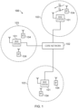
- Figure 1 provides a schematic diagram illustrating some basic functionality of a mobile telecommunications network / system 100 operating generally in accordance with LTE principles, but which may also support other radio access technologies, and which may be adapted to implement embodiments of the disclosure as described herein.
- Various elements of Figure 1 and certain aspects of their respective modes of operation are well-known and defined in the relevant standards administered by the 3GPP (RTM) body and associated proposals, and also described in many books on the subject, for example, Holma H. and Toskala A [5].
- the network 100 includes a plurality of base stations 101 connected to a core network 102. Each base station provides a coverage area 103 within which data can be communicated to and from terminal devices 104. Data is transmitted from base stations 101 to terminal devices 104 within their respective coverage areas 103 via a radio downlink. The coverage area may be referred to as a cell. Data is transmitted from terminal devices 104 to the base stations 101 via a radio uplink.
- the core network 102 routes data to and from the terminal devices 104 via the respective base stations 101 and provides functions such as authentication, mobility management, charging and so on. Terminal devices may also be referred to as mobile stations, user equipment (UE), user terminal, mobile radio, communications device, and so forth.
- Base stations which are an example of network infrastructure equipment / network access node, may also be referred to as transceiver stations / nodeBs / e-nodeBs, g-nodeBs and so forth.
- transceiver stations / nodeBs / e-nodeBs, g-nodeBs and so forth.
- different terminology is often associated with different generations of wireless telecommunications systems for elements providing broadly comparable functionality.
- certain embodiments of the disclosure may be equally implemented in different generations of wireless telecommunications systems, and for simplicity certain terminology may be used regardless of the underlying network architecture. That is to say, the use of a specific term in relation to certain example implementations is not intended to indicate these implementations are limited to a certain generation of network that may be most associated with that particular terminology.
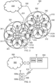
- FIG. 2 is a schematic diagram illustrating a network architecture for a new RAT wireless mobile telecommunications network / system 300 based on previously proposed approaches which may also be adapted to provide functionality in accordance with embodiments of the disclosure described herein.
- the new RAT network 300 represented in Figure 2 comprises a first communication cell 301 and a second communication cell 302.
- Each communication cell 301, 302 comprises a controlling node (centralised unit) 321, 322 in communication with a core network component 310 over a respective wired or wireless link 351, 352.
- the respective controlling nodes 321, 322 are also each in communication with a plurality of distributed units (radio access nodes / remote transmission and reception points (TRPs)) 311, 312 in their respective cells.
- TRPs remote transmission and reception points
- the distributed units 311, 312 are responsible for providing the radio access interface for terminal devices connected to the network.
- Each distributed unit 311, 312 has a coverage area (radio access footprint) 341, 342 which together define the coverage of the respective communication cells 301, 302.
- Each distributed unit 311, 312 includes transceiver circuitry 311a, 312a for transmission and reception of wireless signals and processor circuitry 311b, 312b configured to control the respective distributed units 311, 312.
- the core network component 310 of the telecommunications system represented in Figure 2 may be broadly considered to correspond with the core network 102 represented in Figure 1 , and the respective controlling nodes 321, 322 and their associated distributed units / TRPs 311, 312 may be broadly considered to provide functionality corresponding to base stations of Figure 1 .
- the term network infrastructure equipment / access node may be used to encompass these elements and more conventional base station type elements of wireless telecommunications systems.
- the responsibility for scheduling transmissions which are scheduled on the radio interface between the respective distributed units and the terminal devices may lie with the controlling node / centralised unit and / or the distributed units / TRPs.
- a terminal device 400 is represented in Figure 2 within the coverage area of the first communication cell 301. This terminal device 400 may thus exchange signalling with the first controlling node 321 in the first communication cell via one of the distributed units 311 associated with the first communication cell 301. In some cases communications for a given terminal device are routed through only one of the distributed units, but it will be appreciated in some other implementations communications associated with a given terminal device may be routed through more than one distributed unit, for example in a soft handover scenario and other scenarios.
- the particular distributed unit(s) through which a terminal device is currently connected through to the associated controlling node may be referred to as active distributed units for the terminal device.
- the active subset of distributed units for a terminal device may comprise one or more than one distributed unit (TRP).
- the controlling node 321 is responsible for determining which of the distributed units 311 spanning the first communication cell 301 is responsible for radio communications with the terminal device 400 at any given time (i.e. which of the distributed units are currently active distributed units for the terminal device). Typically this will be based on measurements of radio channel conditions between the terminal device 400 and respective ones of the distributed units 311. In this regard, it will be appreciated the subset of the distributed units in a cell which are currently active for a terminal device will depend, at least in part, on the location of the terminal device within the cell (since this contributes significantly to the radio channel conditions that exist between the terminal device and respective ones of the distributed units).
- the involvement of the distributed units in routing communications from the terminal device to a controlling node is transparent to the terminal device 400. That is to say, in some cases the terminal device may not be aware of which distributed unit is responsible for routing communications between the terminal device 400 and the controlling node 321 of the communication cell 301 in which the terminal device is currently operating. In such cases, as far as the terminal device is concerned, it simply transmits uplink data to the controlling node 321 and receives downlink data from the controlling node 321 and the terminal device has no awareness of the involvement of the distributed units 311. However, in other embodiments, a terminal device may be aware of which distributed unit(s) are involved in its communications. Switching and scheduling of the one or more distributed units may be done at the network controlling node based on measurements by the distributed units of the terminal device uplink signal or measurements taken by the terminal device and reported to the controlling node via one or more distributed units
- two communication cells 301, 302 and one terminal device 400 are shown for simplicity, but it will of course be appreciated that in practice the system may comprise a larger number of communication cells (each supported by a respective controlling node and plurality of distributed units) serving a larger number of terminal devices.
- Figure 2 represents merely one example of a proposed architecture for a new RAT telecommunications system in which approaches in accordance with the principles described herein may be adopted, and the functionality disclosed herein may also be applied in respect of wireless telecommunications systems having different architectures.
- certain embodiments of the disclosure as discussed herein may be implemented in wireless telecommunication systems / networks according to various different architectures, such as the example architectures shown in Figures 1 and 2 , and indeed in networks supporting aspects of different architectures in parallel, for example with co-existence of a legacy radio access network architecture, e.g., as schematically represented in Figure 1 , with a new RAT architecture, e.g., as schematically represented in Figure 2 .
- a legacy radio access network architecture e.g., as schematically represented in Figure 1
- a new RAT architecture e.g., as schematically represented in Figure 2 .
- the specific wireless telecommunications architecture in any given implementation is not of primary significance to the principles described herein.
- the network infrastructure equipment / access nodes may comprise base stations, such as LTE-type base stations 101 as shown in Figure 1 , which are adapted to provide functionality in accordance with the principles described herein, and in other examples the network infrastructure equipment may comprise control units / controlling nodes 321, 322 and / or TRPs 311, 312 of the kind shown in Figure 2 which are adapted to provide functionality in accordance with the principles described herein, and in yet other scenarios the network infrastructure equipment / access nodes may comprise both base stations, such as LTE-type base stations 101 as shown in Figure 1 and control units / controlling nodes 321, 322 and / or TRPs 311, 312 of the kind shown in Figure 2 with at least one being adapted to provide functionality in accordance with the principles described herein
- mobile communications networks such as the network 100 shown in Figure 1 and the network 300 shown in Figure 2 may support services with different characteristics, including services for which reliability, i.e. ensuring a high chance data can be successfully transmitted through the network, is a primary consideration, e.g., for URLLC.
- Certain embodiments of the disclosure propose approaches that seek to help support the reliability of transmissions in a communications networks and may in particular be described in the context of URLLC data (including eURLLC data), but it will be appreciated that while the more stringent requirements associated with new types of data in wireless telecommunications systems may be seen as a driver for improving reliability, an improvement in reliability can be beneficial for any type of data for transmission in wireless telecommunications systems, whether classified as URLLC or similar data or otherwise.
- FIG 3 schematically shows some further details of a telecommunications system 500 supporting communications between a radio access node 504 and a terminal device 506 according to certain embodiments of the present disclosure.
- the telecommunications system 500 here is assumed to be based broadly around an LTE-type architecture that may also support other radio access technologies, either using the same hardware as represented in Figure 3 with appropriately configured functionality, or separate hardware configured to operate in association with the hardware represented in Figure 3 .
- the specific network architecture in which embodiments of the disclosure may be implemented is not of primary significance to the principles described herein. Many aspects of the operation of the telecommunications system / network 500 are known and understood and are not described here in detail in the interest of brevity.
- the network access node 504 may, for convenience, sometimes be referred to herein as a base station 504, it being understood this term is used for simplicity and is not intended to imply any network access node should conform to any specific network architecture, but on the contrary, may correspond with any network infrastructure equipment / network access node that may be configured to provide functionality as described herein. In that sense it will appreciated the specific network architecture in which embodiments of the disclosure may be implemented is not of primary significance to the principles described herein.
- the telecommunications system 500 comprises a core network part 502 coupled to a radio network part.
- the radio network part comprises the radio network access node 504 and the terminal device 506. It will of course be appreciated that in practice the radio network part may comprise more network access nodes serving multiple terminal devices across various communication cells (e.g. as schematically represented in Figure 1 ). However, only one network access node and one terminal device are shown in Figure 3 in the interests of simplicity.
- the terminal device 506 is arranged to communicate data to and from the network access node (base station / transceiver station) 504 or another network access node in the wireless telecommunications system according to coverage.
- the network access node 504 is communicatively connected to the core network part 502 which is arranged to perform routing and management of mobile communications services for terminal devices in the telecommunications system 500 via the network access node 504.
- the connection from the network access nodes 504 to the core network 502 may be wired or wireless.
- the core network part 502 also includes a mobility management entity, MME, which manages the service connections with terminal devices operating in the communications system, such as the terminal device 506.
- MME mobility management entity
- the terminal device 506 is adapted to support operations in accordance with embodiments of the present disclosure as discussed herein.
- the terminal device 506 comprises transceiver circuitry 506a (which may also be referred to as a transceiver / transceiver unit) for transmission and reception of wireless signals and processor circuitry 506b (which may also be referred to as a processor / processor unit) configured to control the terminal device 506.
- the processor circuitry 506b may comprise various sub-units / sub-circuits for providing desired functionality as explained further herein. These sub-units may be implemented as discrete hardware elements or as appropriately configured functions of the processor circuitry.
- the processor circuitry 506b may comprise circuitry which is suitably configured / programmed to provide the desired functionality described herein using conventional programming / configuration techniques for equipment in wireless telecommunications systems.
- the transceiver circuitry 506a and the processor circuitry 506b are schematically shown in Figure 3 as separate elements for ease of representation. However, it will be appreciated that the functionality of these circuitry elements can be provided in various different ways, for example using one or more suitably programmed programmable computer(s), or one or more suitably configured application-specific integrated circuit(s) / circuitry / chip(s) / chipset(s). It will be appreciated the terminal device 506 will in general comprise various other elements associated with its operating functionality, for example a power source, user interface, and so forth, but these are not shown in Figure 3 in the interests of simplicity.
- the network access node 504 comprises transceiver circuitry 504a (which may also be referred to as a transceiver / transceiver unit) for transmission and reception of wireless signals and processor circuitry 504b (which may also be referred to as a processor / processor unit) configured to control the respective network access node 504 to operate in accordance with embodiments of the present disclosure as described herein.
- the processor circuitry 504b for the network access node 504 may comprise circuitry which is suitably configured / programmed to provide the desired functionality described herein using conventional programming / configuration techniques for equipment in wireless telecommunications systems.
- the transceiver circuitry 504a and the processor circuitry 504b are schematically shown in Figure 3 as separate elements for ease of representation.
- circuitry elements can be provided in various different ways, for example using one or more suitably programmed programmable computer(s), or one or more suitably configured application-specific integrated circuit(s) / circuitry / chip(s) / chipset(s).
- the network access node 504 will in general comprise various other elements associated with its operating functionality, such as a scheduler.
- the network access node 504 is configured to communicate data with a terminal device 506 according to an embodiment of the disclosure over communication link 510.
- Certain embodiments of the disclosure relate to apparatus and methods for multiplexing uplink data associated with different services supported by a terminal devices where data associated with one service has a higher priority (in the sense of having more stringent latency and / or reliability requirements) than data associated with another service.
- the higher-priority service may be a URLCC service and the lower-priority service may be an eMBB service.
- the specific nature of the services is not in general of primary significance to the principles discussed herein.
- Uplink Control Information is used in wireless telecommunications systems to transmit control signalling from a terminal device to the network.
- UCI is typically transmitted on a physical uplink control channel, e.g. PUCCH, but can in some circumstances be transmitted on a physical uplink shared channel, e.g. PUSCH.
- PUSCH Physical uplink shared channel
- the UCI in wireless telecommunications systems is typically carried by a Physical Uplink Control Channel (PUCCH).
- PUCCH Physical Uplink Control Channel
- Details on how UCI is handled in wireless telecommunications systems can be found in the relevant specifications, for example in 3GPP TS 38.211, "Physical channels and modulation (Release 15)", v15.6.0 (2019-06 ) [6]; 3GPP TS 38.212, “Multiplexing and channel coding (Release 15)", v15.6.0 (2019-06 ) [7]; 3GPP TS 38.213, “Physical layer procedures for control (Release 15)", v15.6.0 (2019-06 ) [8]; and 3GPP TS 38.331, "Radio Resource Control (RRC) protocol specification (Release 15)” , v15.5.1 (2019-04 ) [9] for the 3GPP NR (New Radio) series.
- RRC Radio Resource Control
- a terminal device can be configured with a number of, e.g. four, sets of potential PUCCH Resources where each set is identified by a PUCCH Resource Set ID ⁇ 0, 1, 2, 3 ⁇ , where each set contains a number of potential PUCCH resources (e.g. in terms of time and frequency radio resources) and a maximum payload (i.e. number of bits to be used for UCI).
- the configurable parameters for each PUCCH Resource Set are summarized in Table 1.
- the values N 2 and N 3 i.e. the maximum number of UCI bits for PUCCH Resource Sets with IDs 1 and 2 are RRC (radio resource control) configurable via the parameter maxPayloadMinus1 which can have a value of between 4 and 256 bits with N 3 > N 2 .
- PUCCH Resource Set ID 0 There are 5 potential PUCCH formats ⁇ 0, 1, 2, 3, 4 ⁇ and the PUCCH resources in PUCCH Resource Set ID 0 can only use PUCCH Format 0 and 1 whilst the other sets can only use PUCCH Format 2, 3 & 4.
- Table 1 PUCCH Resource Set Set ID Number of PUCCH Resources Maximum UCI Bits PUCCH Format 0 8 to 32 (configurable) 3 (2 bits + SR) Format 0 & 1 1 8 N 2 (configurable) Format 2, 3 & 4 2 8 N 3 (configurable) Format 2, 3 & 4 3 8 1706 Format 2, 3 & 4
- FIG. 4 An example of the structure of PUCCH Resource Sets is shown in Figure 4.
- Figure 4 represents four PUCCH Resource Sets (with IDs 0, 1, 2 and 3) and in each set, there are eight PUCCH Resources (with IDs 0 to 7).
- the physical resources e.g. in terms of frequency and time, the PUCCH format and any frequency hopping can be configured for each PUCCH Resource.
- PUCCH Resource Set ID 0 has only 8 PUCCH Resources, the number of PUCCH Resources for this set can range from 8 to 32 (as indicated in Table 1).
- UCI transmitted by a terminal device may comprise a scheduling request (SR), i.e. an indication the terminal device has uplink data for transmission to the network, acknowledgement signalling (e.g. HARQ-ACK signalling) in respect of previously-received downlink transmissions, and an indication of channel status information (CSI), i.e. reporting an indication of channel quality.
- SR scheduling request
- acknowledgement signalling e.g. HARQ-ACK signalling
- CSI channel status information
- a terminal device that wishes to transmit UCI selects a PUCCH Resource Set depending upon the number of UCI bits, N UCI , to be transmitted according to the following principles:
- the terminal device selects one of the PUCCH Resources in this set depending on whether the UCI contains an SR or HARQ-ACK.
- Each potential PUCCH resource in a PUCCH Resource Set provides time and frequency resources for the terminal device to transmit its UCI.
- the starting RB (resource block) of a PUCCH resource is configured per PUCCH resource.
- the number of RBs of a PUCCH resource and the time resources depends on the PUCCH format.
- Table 2 PUCCH Format summary Format UCI Info UCI Bits (N UCI ) Num Symbols Max RB Type 0 SR, HARQ-ACK 1 to 3 1 to 2 1 Sequence 1 SR, HARQ-ACK 1 to 2 4 to 14 1 Sequence 2 SR, HARQ-ACK, CSI > 2 1 to 2 1 to 16 RM/Polar + CRC 3 SR, HARQ-ACK, CSI > 2 4 to 14 1 to 16 RM/Polar + CRC 4 SR, HARQ-ACK, CSI > 2 4 to 14 1 RM/Polar + CRC
- PUCCH Format 0 can carry up to 2 UCI bits and an SR (effectively 3 bits), i.e. 2 HARQ-ACK + 1 SR (Scheduling Request). It is formed from a Zadoff-Chu (ZC) sequence that occupies one RB (12 subcarriers) and 1 or 2 OFDM (orthogonal frequency division multiplex) symbols (i.e. a so-called short PUCCH), where the number of OFDM symbols is configurable.
- ZC Zadoff-Chu
- OFDM orthogonal frequency division multiplex
- PUCCH Format 1 can carry up to 2 UCI bits, for either HARQ-ACK or SR and uses BPSK (Binary Phase Shift Keying) when carrying 1 bit (1 HARQ-ACK or SR) and QPSK (Quadrature Phase Shift Keying) when carrying 2 bits (2 HARQ-ACKs). It occupies one RB (12 subcarriers) in the frequency domain and is configurable to occupy 4 to 14 OFDM symbols (i.e. it is a so-called long PUCCH) in the time domain. The modulated symbol is then multiplied (i.e. spread) using a ZC length 12 sequence in the frequency domain and further spread in the time domain using an orthogonal sequence.
- BPSK Binary Phase Shift Keying
- QPSK Quadrature Phase Shift Keying
- PUCCH Format 2 can carry more than 2 UCI bits for HARQ-ACK, SR and CSI. If N UCI ⁇ 11 bits (small block length), Reed-Muller coding without CRC is used. If N UCI > 11 bits, Polar coding is used with CRC attached.
- the maximum number of RBs for PUCCH Format 2, M RB-MAX is configurable from 1 to 16 and the number of OFDM symbols is configurable from 1 to 2 (short PUCCH).
- the actual number of RBs, M RB-PUCCH used by the PUCCH is determined based on the number of UCI bits (N UCI ) and a configured maximum code rate R UCI , for this PUCCH format.
- the actual number of RBs is calculated by the terminal device by determining the minimum value of M RB-PUCCH that satisfies the following for M RB-MAX > 1: ((M RB-PUCCH - 1) ⁇ N SC-RB ⁇ N Symbol-PUCCH ⁇ Q m ⁇ R UCI ) ⁇ (N UCI + O CRC ) ⁇ (M RB-PUCCH ⁇ N SC-RB ⁇ N Symbol-PUCCH ⁇ Q m ⁇ R UCI ) Where,
- PUCCH Format 3 is similar to PUCCH Format 2 except that it has a longer duration of 4 to 14 OFDM symbols (i.e. it is a long PUCCH). Like Format 2 it can carry more than 2 UCI bits for HARQ-ACK, SR and CSI, and if N UCI ⁇ 11 bits (small block length) Reed-Muller coding without CRC is used and if N UCI > 11 bits, CRC is attached and Polar coding is used.
- the maximum number of RBs, MR B-MAX is configurable from 1 to 16, but the actual number of RBs used is determined based on the number of UCI bits (N UCI ) and a configured maximum code rate R UCI for this format in the same way as described above for PUCCH Format 2.
- PUCCH Format 4 is similar to PUCCH Format 3 except that it occupies one RB and an additional orthogonal code is applied to it so that it can be code multiplexed with other PUCCHs, i.e. multiple PUCCH from different terminal devices can share the same frequency and time resource but can be distinguished based on the orthogonal code.
- PUCCH Format 4 can carry more than 2 UCI bits for HARQ-ACK, SR and CSI, where if N UCI ⁇ 11 bits (small block length) Reed-Muller coding without CRC is used and if N UCI > 11 bits, CRC is attached and Polar coding is used.
- the duration for PUCCH Format 4 is configurable from 4 to 14 OFDM symbols.
- a configurable maximum code rate is also used to determine the maximum number of UCI bits that can be multiplexed into the PUCCH.
- SR Scheduling Request
- SR-ID Scheduling Request ID
- a single stand-alone SR transmission (1 bit) can only use PUCCH Format 0 or Format 1, and each SR-ID is configured to a PUCCH Resource ID in PUCCH Resource Set ID 0, i.e.
- PUCCH Resource Set ID 0 which can only contain PUCCH Format 0 or Format 1). If one or more SR is multiplexed with other UCI such as HARQ-ACK and/or CSI, then other PUCCH formats can be used.
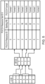
- An example mapping between LCID, SR-ID and PUCCH Resource ID is shown in Figure 5 (it will be appreciated this is only one example mapping and that other mappings can be configured).
- LCID 2 & 3 are configured with SR-ID 0, and hence whenever data arrives in either LCID 2 or LCID 3, this condition will trigger an SR corresponding to the SR-ID 0 configuration.
- This will in turn use a PUCCH resource according to that configured for PUCCH Resource ID 1, which in the example of Figure 5 has a starting RB of 5 and uses PUCCH Format 0.
- the other LCIDs are similarly mapped to their corresponding SR-IDs and the PUCCH Resource ID used to transmit those SR-IDs.
- Figure 5 represents only one example configuration and other LCID to SR-ID and SR-ID to PUCCH Resource ID configurations can be used, and also each PUCCH Resource ID can be configured with different starting RB locations and PUCCH Formats (either 0 or 1).
- Each SR-ID is also configured with a periodicity which can range from 2 symbols (for any subcarrier spacing) to 80, 160, 320 & 640 slots for subcarrier spacing 15 kHz, 30 kHz, 60 kHz and 120 kHz respectively.
- a time offset can also be configured for each SR-ID, which facilitates multiplexing of SR-ID and differentiation between different SR-ID.
- the base station Since there is a one-to-one mapping between PUCCH Resource ID (in PUCCH Resource Set ID 0) and SR ID, the base station is able to determine which LCID(s) have triggered the SR based on the PUCCH frequency resource (starting RB) and time resource (periodicity, offset, starting symbol and duration) used to transmit that SR.
- a stand-alone SR is only transmitted if it is positive, i.e. being triggered by one or more LCIDs, while an indication of a negative SR may be sent in conjunction with other signalling (e.g. HARQ feedback).
- HARQ-ACK Hybrid Automatic Repeat Request acknowledgement signalling
- feedback is transmitted by the terminal device to the base station in respect of PDSCH scheduling to inform the base station whether the terminal device has successfully decoded the corresponding PDSCH or not. If the terminal device has successfully decoded the relevant PDSCH transmission the terminal device transmits an ACK indication, and if the terminal device has not successfully decoded the relevant PDSCH transmission the terminal device transmits a NACK indication.
- acknowledgement signalling may be used to refer to HARQ signalling regardless of whether the acknowledgement signalling is indicating an ACK or a NACK.
- the corresponding PUCCH carrying the HARQ-ACK is transmitted in slot n+K 1 , where the value of K 1 is indicated in the field "PDSCH-to-HARQ_feedback timing indicator" in the downlink (DL) Grant (carried by DCI (downlink control information) Format 1_0 or DCI Format 1_1).
- Multiple (different) PDSCHs can point to the same slot for transmission of their respective HARQ-ACKs, and multiple HARQ-ACKs in the same slot can be multiplexed into a single PUCCH.
- a PUCCH can contain multiple HARQ-ACKs for multiple PDSCHs. An example of this is represented Figure 6 .
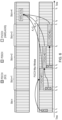
- Figure 6 schematically shows an uplink radio resource grid (top half of figure) and downlink radio resource grid (bottom half of figure) representing radio resources in time (horizontal axis) and frequency (vertical axis).
- Figure 6 schematically shows radio resources used by a terminal device in an example scenario during a period spanning five slots (identified in Figure 6 as slots n to n+4).
- DCI#1 downlink control information
- PDSCH#1 physical downlink shared channel
- the HARQ-ACK feedbacks for each of the three downlink transmissions on the physical downlink shared channel are transmitted by the terminal device in slot n+4 in a multiplexed manner.
- a Multiplexing Window may be defined, wherein the Multiplexing Window is a time window indicating how many PDSCHs can have their associated HARQ-ACK signalling multiplexed in PUCCH in a single slot and may depend on the range of K 1 values.
- the PUCCH Multiplexing Window is assumed to be from Slot n to Slot n+3, which means the max K 1 value that can be used in this period is 4.
- the terminal device To transmit multiplexed HARQ-ACK signalling the terminal device firstly determines the PUCCH Resource Set to use based on the number of HARQ-ACK bits to be transmitted, i.e. N UCI bits as described above. Once the PUCCH Resource Set is determined, the terminal device then determines the PUCCH Resource ID of the selected PUCCH Resource Set to use. For a PUCCH Resource Set with 8 PUCCH resources, the PUCCH Resource ID to use is indicated by the PUCCH Resource Indicator (PRI) in the DL Grant scheduling the last PDSCH (i.e. the PRI field in DCI Format 1_0 and DCI Format 1_1).
- PRI PUCCH Resource Indicator
- the terminal device For PUCCH Resource Set ID 0 with more than 8 configured PUCCH resources, in addition to the PRI, the terminal device also uses the CCE (Control Channel Element) index of the PDCCH carrying the DL Grant scheduling the last PDSCH whose HARQ-ACK signalling is to be multiplexed, i.e. the last PDSCH in the PUCCH Multiplexing Window (for example in Figure 6 , the last PDSCH is PDSCH#3).
- CCE Control Channel Element
- FIG. 7 An example of a PUCCH Resource ID selection by a terminal device with 3 HARQ-ACK feedbacks to multiplex in UCI in a single slot (e.g. as for the Example in Figure 6 ) is shown in Figure 7.
- Figure 7 is similar to, and will be understood from, Figure 4 with N 2 (Max Payload for PUCCH Resource Set ID 1) configured to 20 bits and N 3 (Max Payload for PUCCH Resource Set ID 2) configured to 60 bits (it will be appreciated these are simply example values).
- Figure 7 also indicates in these example circumstances the terminal device selects PUCCH Resource ID 6 in PUCCH Resource Set ID 1.
- N UCI 3
- a terminal device it is possible for a terminal device to be in a situation in which a UCI carrying an SR for the terminal device and another UCI carrying HARQ-ACK feedback collide in the same slot.
- the SR and the HARQ-ACK feedback in the same slot are multiplexed into a single UCI taking account of the following principles.
- an SR UCI scheduled to be carried by a first PUCCH using PUCCH Format 1 collides with a HARQ-ACK UCI scheduled to be carried by a second PUCCH using Format 1, then if the SR is positive, the UCI with the HARQ-ACK is transmitted using the first PUCCH but if the SR is negative the HARQ-ACK is transmitted using the second PUCCH.
- a terminal device is configured to potentially transmit multiple SRs, e.g. a number K SR SRs which map to K SR different SR-IDs, and their configured periodicities collide in a particular slot, and in this same specific slot a second PUCCH scheduled to carry a number O ACK of HARQ-ACK bits using either Format 2, Format 3 or Format 4, is also transmitted, then the SRs are multiplexed into the second PUCCH.
- SRs e.g. a number K SR SRs which map to K SR different SR-IDs, and their configured periodicities collide in a particular slot
- a second PUCCH scheduled to carry a number O ACK of HARQ-ACK bits using either Format 2, Format 3 or Format 4 is also transmitted, then the SRs are multiplexed into the second PUCCH.
- This functionality basically corresponds with forming what might be termed an SR Indication Lookup Table (SILT) with K SR +1 entries and the appended O SR bits point to one of these entries to indicate which SR-ID has a positive SR.
- SILT SR Indication Lookup Table
- Figure 8 A schematic example SILT and mapping of SR-IDs to entries in the SILT is schematically shown in Figure 8 .
- O CRC the number of CRC bits
- some embodiments of the disclosure provide a method of operating a terminal device in a wireless telecommunications system that comprises determining a scheduling request (or more generally, first uplink control information) should be transmitted using a first set of radio resources; determining an indication of a priority level for the scheduling request; determining additional uplink control information (e.g. HARQ-ACK and / or CSI information) should be transmitted using a second set of radio resources; determining an indication of a priority level for the additional uplink control information; determining if there is an overlap (i.e.
- certain embodiments of the disclosure involve aspects such as (i) determining a priority level for uplink control information (including SRs, HARQ-ACK and CSI); (ii) selecting a set of radio resources to transmit multiplexed control information; and (iii) multiplexing different types of control information together in a manner which takes account of different priority levels for the different types of control information for transmission on the selected set of radio resources.
- first uplink control information comprising a scheduling request, SR
- second uplink control information comprising acknowledgement signalling (HARQ-ACK)
- HARQ-ACK acknowledgement signalling
- SR UCI scheduling request UCI
- each UCI type (e.g. SR, HARQ-ACK, CSI) is associated with a number of different priority groups, wherein each priority group is associated with a priority level.
- the number of priority groups for each different type of UCI may be different, e.g. SR might have three priority groups (which may be referred to as SR Priority Groups) while HARQ-ACK might have two groups (which may be referred to as HARQ-ACK Priority Groups). It will be appreciated that other numbers of priority groups could be used.
- scheduling requests are associated with a scheduling request identifier, SR-ID.
- each of eight SR-IDs might be associated with a different one of eight priority levels (i.e. so each priority group is associated with one SR-ID).
- the HARQ-ACK UCls may have a different number of priority levels.
- the HARQ-ACKs can be grouped into two priority levels, high priority and low priority, for example based on the nature of service with which the UCI are associated. For example, HARQ-ACK feedback for a URLLC service may be classed as high priority while HARQ-ACK feedback for an eMBB service may be classed as low priority.
- a UCI might be classed as "high priority” if its priority group is higher than or equal to a predetermined threshold priority level, and otherwise might be classed as "low priority”. This allows each UCI type to be classified as either "high priority” or "low priority” to simplify direct comparison of relative priorities for different UCI types regardless of the number of priority groups defined for each UCI type.
- the SR-IDs may be divided into three priority groups ⁇ SR Group 1, SR Group 2, SR Group 3 ⁇ where the lower the group number the higher the priority.
- the HARQ-ACK on the other hand, may be divided into four priority groups ⁇ ACK Group 1, ACK Group 2, ACK Group 3, ACK Group 4 ⁇ , and similarly the lower the group number the higher the priority.
- SR group 2 should have a higher or lower priority than ACK group 2.
- a predetermined threshold priority level for SR is set at the priority level of SR Group 2
- SR UCls associated with SR Groups 1 and 2 will be classified as high priority
- SR UCls associated with SR Group 3 will be classified as low priority.
- HARQ-ACK is set at the priority level of ACK Group 3
- HARQ-ACK UCIs associated with ACK Groups 1, 2 and 3 will be classified as high priority
- HARQ-ACK UCIs associated with ACK Group 4 will be classified as low priority.
- more than one predetermined threshold priority level can be defined for each UCI type to give more classifications, e.g. two threshold levels can provide for classification of UCls as "high priority", “mid priority” and “low priority”.
- two threshold levels can provide for classification of UCls as "high priority", “mid priority” and "low priority”.
- the priority levels of different types of UCI can be more easily directly compared.
- the number of priority groups might be the same for different types of UCI (e.g. SR-IDs may be divided into 3 priority groups and HARQ-ACK may also take one of three priority levels). Since the number of priority groups is the same among different UCI types, they can be compared against each other directly without a threshold-based priority normalising function.
- priority levels for each UCI type it will be helpful for priority levels for each UCI type to be determined at the physical layer, and there are various different ways this can be done.
- separate PUCCH Resource Sets may be configured for different services (e.g. URLLC or eMBB) having different maximum code rates and numbers of resource blocks (M RB-MAX ), and so on.
- the priority level for a UCI can then be determined at the physical layer from the PUCCH Resource Set being used. That is to say, in accordance with certain embodiments of the disclosure, the priority level for a UCI may be determined from the PUCCH Resources scheduled for that UCI.
- Other approaches as discussed further below, can allow a priority level for a UCI to be determined at the physical layer without defining separate PUCCH Resource Sets for different services.
- a priority level for each SR UCI may be determined by the maximum code rate of the PUCCH Resource assigned to the SR transmission, whereby lower maximum code rates are determined to correspond to higher priority SRs. It will be appreciated the maximum code rate for a UCI is visible at the terminal device physical layer so the terminal device can calculate the number of RBs to be used for the PUCCH.
- a priority level for each SR may be determined from its associated SR-ID.
- One simple implementation for this would be that the lower the SR-ID the higher its priority.
- a base station can then ensure that high priority services are associated with low-numbered SR-IDs. It will be appreciated the SR-ID is visible at the terminal device physical layer so the terminal device can calculate the relevant PUCCH Resource ID using a SILT such as represented in Figure 5 .
- a priority level for each SR may be determined from the duration of the UCI's scheduled PUCCH Resource. How the duration of the UCls scheduled PUCCH Resource maps to a priority level will depend on the implementation at hand. For example, if high reliability is considered a primary defining factor for classifying a UCI as high priority, then longer durations for the PUCCH Resource for a UCI may be determined to represent higher priority (since these will indicate the UCI has been scheduled with a relatively long duration transmission to improve reliability).
- a priority level for each SR may be determined from its periodicity.
- each SR-ID is configured with a periodicity and this is known to the physical layer.
- a relatively short periodicity for an SR-ID may be determined to indicate a relatively high priority level because it may be expected for some implementations that a high priority service is associated with a requirement for low latency, and so relatively low periodicity may be configured for the SR-ID so that transmissions can be made relatively frequently.
- a priority level for each SR may be determined from a PUCCH Format used to carry the SR.
- the PUCCH Format is known to the terminal device at the physical layer.
- PUCCH Format 0 may be considered higher priority than PUCCH Format 1 or vice-versa, depending on how higher layers (i.e. layers higher than the physical layer) are configured to associate different priority services with different PUCCH formats.
- a priority level for each SR may be determined at the physical layer from an indication received from the MAC (Medium Access Control) layer. That is to say, the MAC layer may, in addition to triggering the transmission of an SR representing an SR-ID, also indicate the priority of that SR transmission to the physical layer.
- the MAC layer may, in addition to triggering the transmission of an SR representing an SR-ID, also indicate the priority of that SR transmission to the physical layer.
- a priority level for each HARQ-ACK UCI may be determined from an indication of the priority level received in association with a resource allocation message (DL Grant) for the downlink signalling to which the HARQ-ACK UCI relates. If the HARQ-ACK UCI relates to downlink signalling for multiple DL Grants with different priority levels, the priority level for the UCI may, for example, be determined as the highest of these.
- DL Grant resource allocation message
- a priority level for each HARQ-ACK UCI may be determined from the scheduled PUCCH resources for the UCI. For example a PUCCH Resource with a low PUCCH Resource ID may be taken to indicate higher priority or vice-versa. This approach may thus take account of the indicated PRI indicator in the DL Grant being acknowledged to also indicate a priority level for the PUCCH for the corresponding HARQ-ACK UCI.
- a priority level for each HARQ-ACK UCI may be determined by the code rate of the scheduled PUCCH Resource for the HARQ-ACK UCI transmission, whereby a lower code rate is determined to correspond to a higher priority HARQ-ACK UCI.
- a priority level for each HARQ-ACK UCI may be determined from a sub-slot size for transmitting the HARQ-ACK UCI.
- the possibility of sub-slot operation for HARQ-ACK is a recently introduced proposal for some wireless telecommunications systems, for example in Release 16 of the 3GPP standards specifications series.
- Sub-slot operation for HARQ-ACK allows the timings of HARQ-ACK UCI to be configured with a resolution which is less than one slot (i.e. the HARQ-ACK process operates with sub-slot timing granularity).
- a HARQ-ACK UCI configured for sub-slot operation may be determined to have a high priority as compared to a HARQ-ACK UCI not configured for sub-slot operation (which reflects the fact a service with more stringent latency requirements will be configured for sub-slot operation).
- HARQ-ACK UCI priority may be determined from the configured sub-slot size with a shorter sub-slot size indicating a higher priority.
- a HARQ-ACK UCI configured for sub-slot operation may be determined to have a low priority as compared to a HARQ-ACK UCI not configured for sub-slot operation (which reflects the fact a service with less stringent reliability requirements will be configured for sub-slot operation).
- the particular mapping between a given sub-slot size and priority level will depend on how the system is configured to use sub-slot sizes according to priority (i.e. whether latency or reliability is considered most important).
- a first UCI carried by a first PUCCH may be considered to collide with a second UCI carried by a second PUCCH if the first PUCCH and the second PUCCH are scheduled in the same slot, sub-slot, or more generally overlap in time, i.e. there is an overlap in time between the respective sets of radio resources associated with the first and second PUCCH.
- Certain aspects of the disclosure relate to selecting one of the respective sets of radio resources associated with the first and second PUCCH to use for transmitting the first UCI and / or the second UCI following a priority-based decision on whether and how to multiplex them.
- a recent development in some wireless telecommunications systems e.g.
- Figure 9 schematically shows an uplink radio resource grid (top half of figure) and downlink radio resource grid (bottom half of figure) representing radio resources in time (horizontal axis) and frequency (vertical axis).
- Figure 9 is similar to, and will be understood from, Figure 6 , but shows an example which incorporates sub-slot operation with a sub-slot size of 0.5 slots (e.g. 7 symbols for a 14 symbol slot size).
- Figure 9 schematically shows radio resources used by a terminal device in an example scenario during a period spanning five slots (identified in Figure 9 as slots n to n+4) / ten sub-slots (identified in Figure 9 as sub-slots m to m+9).
- slot n i.e.
- DCI#1 downlink control information
- PDSCH#1 physical downlink shared channel
- K 1 6 (in units of sub-slots).
- DCI#2 downlink control information
- PDSCH#2 physical downlink shared channel
- K 1 4 (in units of sub-slots).
- HARQ-ACK2 associated with the allocation of radio resources spanning sub-slots m+4 and m+5 is transmitted in sub-slot m+9 (i.e. m+5+ K 1 ), which is in slot n+4, since the reference sub-slot for K 1 is the sub-slot in which the PDSCH ends, and in this example case PDSCH#2 ends in sub-slot m+5.
- first type of UCI e.g. SR UCI
- first PUCCH first set of radio resources
- second type of UCI e.g. one or more HARQ-ACK UCls
- PUCCHs radio resources
- Figure 10 schematically shows a portion of an uplink radio resource grid representing radio resources in time (horizontal axis) and frequency (vertical axis) for one example implementation of an approach according to an example of the disclosure.
- Figure 10 schematically shows radio resources scheduled for use by a terminal device for UCI in an example scenario during a period spanning two slots (identified in Figure 10 as slots n and n+1) / four sub-slots (identified in Figure 10 as sub-slots m to m+3).
- a first PUCCH (which in this example is assumed to be for an SR UCI) is scheduled between times t1 and t3 (which is in sub-slot m in slot n) and a second PUCCH (which in this example is assumed to be for a HARQ-ACK UCI) is scheduled between times t0 and t2 (which is again in sub-slot m in slot n).
- the terminal device determines whether and how to multiplex the SR UCI and HARQ-ACK UCI in accordance with the principles disclosed herein and transmits the resulting multiplexed UCI using radio resources for a selected one of the PUCCH, which in this example is assumed to be the second PUCCH, as schematically indicated by the surrounding dotted-line.
- Figure 11 schematically shows a portion of an uplink radio resource grid representing radio resources in time (horizontal axis) and frequency (vertical axis) for one example implementation of an approach according to an example of the disclosure.
- Figure 11 schematically shows radio resources scheduled for use by a terminal device for UCI in an example scenario during a period spanning two slots (identified in Figure 11 as slots n and n+1) / four sub-slots (identified in Figure 11 as sub-slots m to m+3).
- a first PUCCH (which in this example is assumed to be for an SR UCI) is scheduled between times t1 and t3 (i.e.
- the terminal device determines whether and how to multiplex the SR UCI and HARQ-ACK UCI in accordance with the principles disclosed herein and transmits the resulting multiplexed UCI using radio resources for a selected one of the PUCCH, which in this example is assumed to be the second PUCCH, as schematically indicated by the surrounding dotted-line.
- Figure 12 schematically shows a portion of an uplink radio resource grid representing radio resources in time (horizontal axis) and frequency (vertical axis) for one example implementation of an approach according to an example of the disclosure.
- Figure 12 schematically shows radio resources scheduled for use by a terminal device for UCI in an example scenario during a period spanning two slots (identified in Figure 12 as slots n and n+1) / four sub-slots (identified in Figure 12 as sub-slots m to m+3).
- a first PUCCH (which in this example is assumed to be for an SR UCI) is scheduled between times t2 and t5 (i.e.
- a second PUCCH (which in this example is assumed to be for a HARQ-ACK UCI, labelled HARQ-ACK UCI1) is scheduled between times t1 and t3 (which is in sub-slot m in slot n), and a third PUCCH (which in this example is assumed to be for another HARQ-ACK UCI, labelled HARQ-ACK UCI2) is scheduled between times t4 and t6 (which is in sub-slot m+1 in slot n).
- the terminal device determines whether and how to multiplex the SR UCI with a selected one of HARQ-ACK UCI1 and HARQ-ACK UCI2 in accordance with the principles disclosed herein and transmits the resulting multiplexed UCI using radio resources for the corresponding PUCCH of the selected one of HARQ-ACK UCI1 and HARQ-ACK UCI2, which in this example is assumed to be the second PUCCH (for HARQ-ACK UCI1), as schematically indicated by the surrounding dotted-line.
- the selected set of radio resources for transmitting the multiplexed UCI may be the earlier in time of the second set of radio resources and the third set of radio resources. This allows for the multiplexed UCI to be transmitted sooner than if the selected set of radio resources for transmitting the multiplexed UCI were the later in time of the second set of radio resources and the third set of radio resources, which can help satisfy latency requirements.
- Figure 13 schematically shows a portion of an uplink radio resource grid representing radio resources in time (horizontal axis) and frequency (vertical axis) for one example implementation of an approach according to an example of the disclosure.
- Figure 13 schematically shows radio resources scheduled for use by a terminal device for UCI in an example scenario during a period spanning two slots (identified in Figure 13 as slots n and n+1) / four sub-slots (identified in Figure 13 as sub-slots m to m+3).
- a first PUCCH (which in this example is assumed to be for an SR UCI) is scheduled between times t2 and t5 (i.e.
- a second PUCCH (which in this example is assumed to be for a HARQ-ACK UCI, labelled HARQ-ACK UCI1) is scheduled between times t4 and t6 (which is in sub-slot m+1 in slot n), and a third PUCCH (which in this example is assumed to be for another HARQ-ACK UCI, labelled HARQ-ACK UCI2) is scheduled between times t1 and t3 (which is in sub-slot m in slot n).
- the terminal device determines whether and how to multiplex the SR UCI with a selected one of HARQ-ACK UCI1 and HARQ-ACK UCI2 in accordance with the principles disclosed herein and transmits the resulting multiplexed UCI using radio resources for the corresponding PUCCH of the selected one of HARQ-ACK UCI1 and HARQ-ACK UCI2, which in this example is assumed to be the second PUCCH (for HARQ-ACK UCI1), as schematically indicated by the surrounding dotted-line.
- the selected set of radio resources for transmitting the multiplexed UCI may be the later in time of the second set of radio resources and the third set of radio resources. This allows for the multiplexed UCI to be transmitted later than if the selected set of radio resources for transmitting the multiplexed UCI were the earlier in time of the second set of radio resources and the third set of radio resources.
- One application of this approach would be to select the third PUCCH, as opposed to the second PUCCH, to implicitly indicate the SR priority.
- the later third PUCCH may be used, but if the SR priority is high, the earlier second PUCCH may be used instead.
- the network may then blind decode for the presence of the SR in the second and third PUCCH.
- Figure 14 schematically shows a portion of an uplink radio resource grid representing radio resources in time (horizontal axis) and frequency (vertical axis) for one example implementation of an approach according to an example of the disclosure.
- Figure 14 schematically shows radio resources scheduled for use by a terminal device for UCI in an example scenario during a period spanning two slots (identified in Figure 14 as slots n and n+1) / four sub-slots (identified in Figure 14 as sub-slots m to m+3).
- a first PUCCH (which in this example is assumed to be for an SR UCI) is scheduled between times t2 and t5 (i.e.
- a second PUCCH (which in this example is assumed to be for a HARQ-ACK UCI, labelled HARQ-ACK UCI1) is scheduled between times t4 and t6 (which is in sub-slot m+1 in slot n and spans four symbols), and a third PUCCH (which in this example is assumed to be for another HARQ-ACK UCI, labelled HARQ-ACK UCI2) is scheduled between times t1 and t3 (which is in sub-slot m in slot n and spans two symbols).
- the terminal device determines whether and how to multiplex the SR UCI with a selected one of HARQ-ACK UCI1 and HARQ-ACK UCI2 in accordance with the principles disclosed herein and transmits the resulting multiplexed UCI using radio resources for the corresponding PUCCH of the selected one of HARQ-ACK UCI1 and HARQ-ACK UCI2, which in this example is assumed to be the second PUCCH (for HARQ-ACK UCI1), as schematically indicated by the surrounding dotted-line.
- the selected set of radio resources for transmitting the multiplexed UCI may be the set of radio resources having the greatest potential capacity for carrying UCI.
- each PUCCH resource is associated with a PUCCH format that has a fixed or configurable maximum payload, i.e. potential capacity.
- the selected set of radio resources for transmitting the multiplexed UCI may be the set of radio resources associated with the lowest code rate for its UCI in the expectation the radio resources associated with the lowest code rate may able to more reliably accommodate the additional UCI.
- Figure 15 schematically shows a portion of an uplink radio resource grid representing radio resources in time (horizontal axis) and frequency (vertical axis) for one example implementation of an approach according to an example of the disclosure.
- Figure 15 schematically shows radio resources scheduled for use by a terminal device for UCI in an example scenario during a period spanning two slots (identified in Figure 15 as slots n and n+1) / four sub-slots (identified in Figure 15 as sub-slots m to m+3).
- a first PUCCH (which in this example is assumed to be for an SR UCI) is scheduled between times t2 and t5 (i.e.
- a second PUCCH (which in this example is assumed to be for a HARQ-ACK UCI, labelled HARQ-ACK UCI1) is scheduled between times t4 and t6 (which is in sub-slot m+1 in slot n and spans four symbols), and a third PUCCH (which in this example is assumed to be for another HARQ-ACK UCI, labelled HARQ-ACK UCI2) is scheduled between times t1 and t3 (which is in sub-slot m in slot n and spans two symbols).
- the terminal device may determine to multiplex the SR UCI with both HARQ-ACK UCI1 and HARQ-ACK UCI2 in accordance with the principles disclosed herein and transmit the resulting multiplexed UCls using radio resources for both the corresponding PUCCHs for HARQ-ACK UCI1 and HARQ-ACK UCI2, as schematically indicated by the surrounding dotted-line.
- the terminal device may multiplex the SR UCI with both HARQ-ACK UCI1 and HARQ-ACK UCI2 depending on the implementation at hand.
- the SR UCI may be multiplexed independently with both HARQ-ACK UCI1 and HARQ-ACK UCI2. That is to say, the same SR UCI may be separately selectively multiplexed with both HARQ-ACK UCI1 and HARQ-ACK UCI2 to provide redundancy (duplication) for transmission of the SR UCI. In some cases this may result in the SR UCI being multiplexed with HARQ-ACK UCI1 and HARQ-ACK UCI2 in the same way (e.g.
- the same SR UCI bits are transmitted with both HARQ-ACK UCI1 and HARQ-ACK UCI2), for example when HARQ-ACK UCI1 and HARQ-ACK UCI2 have the same priority level, and in some cases this may result in the SR UCI being multiplexed with HARQ-ACK UCI1 and HARQ-ACK UCI2 in different ways (e.g.
- SR UCI bits are transmitted with HARQ-ACK UCI1 and HARQ-ACK UCI2), for example when HARQ-ACK UCI1 and HARQ-ACK UCI2 have different priority levels there may be fewer bits used for SR UCI to allow for more bits to be used for whichever of HARQ-ACK UCI1 and HARQ-ACK UCI2 has the highest priority.
- the SR UCI comprises multiple bits
- a first portion of SR UCI may be multiplexed with HARQ-ACK UCI1 while a second portion of SR UCI may be multiplexed with HARQ-ACK UCI2 (i.e.
- the multiplexing of SR UCI is split across both HARQ-ACK UCI1 and HARQ-ACK UCI2 rather than being separately multiplexed with each independently). For example, a number of bits of the SR UCI may be multiplexed into a selected one of HARQ-ACK UCI1 and HARQ-ACK UCI2 until a maximum allowed code rate for the selected one of HARQ-ACK UCI1 and HARQ-ACK UCI2 is reached with the remaining contents of the SR UCI being multiplexed into the other one of HARQ-ACK UCI1 and HARQ-ACK UCI2.
- the selected one of HARQ-ACK UCI1 and HARQ-ACK UCI2 may be based on one more of: the timing of the corresponding PUCCHs, for example, the selected one of HARQ-ACK UCI1 and HARQ-ACK UCI2 may be the earliest one; the remaining capacity for the set of radio resources for the respective ones of HARQ-ACK UCI1 and HARQ-ACK UCI2, for example the selected one of HARQ-ACK UCI1 and HARQ-ACK UCI2 may be the one with greatest spare capacity; and the maximum potential capacity for the set of radio resources for the respective ones of HARQ-ACK UCI1 and HARQ-ACK UCI2, for example the selected one of HARQ-ACK UCI1 and HARQ-ACK UCI2 may be the one with greatest maximum potential capacity.
- a terminal device may be configured to selectively multiplex first uplink control information (e.g. SR UCI) and second uplink control information (e.g. HARQ-ACK UCI) in a way which takes account of their respective priority levels.
- first uplink control information e.g. SR UCI
- second uplink control information e.g. HARQ-ACK UCI
- Some general considerations for determining how to multiplex uplink control data in accordance with certain examples of the disclosure include seeking to maintain an acceptable level of reliability and latency of the multiplexed UCI, for example having regard to the reliability and latency requirements of the highest priority UCI.
- a terminal device determines that first uplink control information (which in this example is assumed to comprise SR UCI) associated with a first priority level should be sent using a first set of radio resources corresponding to a first PUCCH and that second uplink control information (which in this example is assumed to comprise HARQ-ACK UCI) associated with a second priority level should be sent using a second set of radio resources corresponding to a second PUCCH, and that there is an overlap in the first and second sets of radio resources.
- This scenario may happen in accordance with the normal operation of the terminal device and the specific reasons why the scenario has arisen, for example in terms of the specific content of the UCls, is not relevant to the principles discussed herein.
- the decision on whether or not to multiplex the SR UCI and the HARQ-ACK UCI onto one or other of the first PUCCH and second PUCCH may take account of the resulting code rate for the multiplexed UCI on the selected PUCCH (which may be referred to herein as the multiplexed PUCCH). For example, if the code rate of the multiplexed PUCCH would be lower or equal to a predetermined threshold code rate (i.e. the code rate that would be applied to the 3rd PUCCH after the multiplexing operation is lower or equal to a predetermined value), the UCls may be multiplexed and transmitted on the multiplexed PUCCH.
- a predetermined threshold code rate i.e. the code rate that would be applied to the 3rd PUCCH after the multiplexing operation is lower or equal to a predetermined value
- the predetermined threshold code rate is the lower of a code rate associated with the SR UCI (if transmitted on the first PUCCH) and a code rate associated with the HARQ-ACK UCI (if it were transmitted on the first PUCCH). In a case where none of the PUCCH can meet the code rate threshold, then the terminal device may select the lower priority UCI to drop / compress.
- the terminal device may be configured to multiplex the UCls in such a way that reduces the number of bits used for the lower priority UCI (e.g. by dropping some of the bits for the lower priority UCI or by applying data compression to the bits for the lower priority UCI).
- the decision on whether or not to multiplex the SR UCI and the HARQ-ACK UCI onto one or other of the first PUCCH and second PUCCH may take account of any consequent delays in the transmission of the SR UCI and / or the HARQ-ACK UCI, and an example implementation scenario for this is discussed with reference to Figure 16 .
- Figure 16 schematically shows a portion of an uplink radio resource grid representing radio resources in time (horizontal axis) and frequency (vertical axis) for one example implementation of an approach according to an example of the disclosure.
- Figure 16 schematically shows radio resources scheduled for use by a terminal device for UCI in an example scenario during a period spanning two slots (identified in Figure 16 as slots n and n+1).
- a first PUCCH (which in this example is assumed to be for an SR UCI) is scheduled between times t1 and t3 (which is in slot n)
- a second PUCCH (which in this example is assumed to be for a HARQ-ACK UCI) is scheduled between times t2 and t4 (which is again in slot n).
- the terminal device determines whether to multiplex the UCIs.
- multiplexing the SR UCI onto the HARQ-ACK UCI would result in completion of transmission for the SR UCI at time t4, which is five symbols after the end of its initially scheduled transmission on the first PUCCH. Whether or not this is acceptable will depend on the latency requirements for the earliest of the UCls.
- the terminal device will choose not to multiplex the SR UCI and the HARQ UCI if it would result in a transmission delay for the SR UCI which is greater than a predetermined threshold delay.
- the terminal device would choose not to multiplex the SR UCI onto the HARQ UCI and would instead transmit the SR UCI on the first PUCCH if the SR UCI has higher priority than the HARQ UCI, otherwise the HARQ UCI is transmitted.
- the multiplexed PUCCH (i.e. the PUCCH used to transmit the multiplexed UCIs) is a selected one of the first PUCCH and the second PUCCH and is chosen to be the one that would result in the lowest latency. That is to say, the multiplexed PUCCH (selected PUCCH) is the PUCCH which ends first in time.
- This approach may be beneficial in a scenario where the SR UCI and HARQ-ACK UCI have equal priority level and so the terminal device acts to transmit both UCI, through multiplexing, rather than dropping one of them.
- the multiplexed PUCCH (i.e. the PUCCH used to transmit the multiplexed UCIs) is a selected one of the first PUCCH and the second PUCCH and is chosen to be the one that would result in the lowest code rate (highest reliability) for transmitting the multiplexed UCI.
- This approach may be beneficial in a scenario where the SR UCI and HARQ-ACK UCI have equal priority level and so the terminal acts to transmit, through multiplexing, both UCI rather than dropping one of them.
- the multiplexed PUCCH (i.e. the PUCCH used to transmit the multiplexed UCIs) is not a selected one of the first PUCCH and the second PUCCH but is a different PUCCH associated with a different set of radio resources, and an example implementation scenario for this is discussed with reference to Figure 17.
- Figure 17 schematically shows two versions of a portion of an uplink radio resource grid representing radio resources in time (horizontal axis) and frequency (vertical axis) for one example implementation of an approach according to an example of the disclosure.
- Figure 17 schematically shows radio resources scheduled for use by a terminal device for UCI in an example scenario during a period spanning two slots (identified in Figure 17 as slots n and n+1).
- the left-hand representation of the portion of the uplink radio resource grid in Figure 17 indicates example sets of radio resources scheduled for transmitting two types of UCI and the right-hand representation of the portion of the uplink radio resource grid in Figure 17 indicates an example set of radio resources used for transmitting the two types of UCI in a multiplexed manner.
- a first PUCCH (which in this example is assumed to be for an SR UCI) is scheduled between times t1 and t3 (which is in slot n)
- a second PUCCH (which in this example is assumed to be for a HARQ-ACK UCI) is scheduled between times t2 and t5 (which is again in slot n).
- the terminal device determines to multiplex the UCls. However, and as indicated in the right-hand representation of the portion of the uplink radio resource grid in Figure 17 , rather than using one or other of the scheduled set of radio resources for transmitting the SR UCI or the HARQ-ACK UCI, the terminal device uses a different set of radio resources for transmitting the multiplexed SR UCI and HARQ-ACK UCI, and in particular for this example uses a set of radio resources between t1 and t4.
- the terminal device uses the PUCCH frequency resource and format of the most reliable PUCCH (in this case the second PUCCH) while starting at the earliest of the start times for the first and second PUCCHs.
- This approach can be beneficial in a scenario where the SR UCI and HARQ-ACK UCI have equal priority level and so the terminal device acts to transmit both UCI rather than dropping one of them.
- the UCI associated with the highest priority level is an SR UCI.
- the UCI having the lowest priority is not transmitted.
- the multiplexing conditions may depend on a transmission format associated with the multiplexed PUCCH (i.e. the transmission format associated with the set of radio resources used to transmit the multiplexed UCIs) as explained below. For this explanation it will be assumed there is an overlap in a first set of radio resources associated with a first PUCCH for transmitting SR UCI and a second set of radio resources associated with a second PUCCH for transmitting HARQ-ACK UCI.
- the SR if the SR is positive it is multiplexed with the HARQ-ACK UCI on the second PUCCH if the second PUCCH uses PUCCH Format 0, regardless of the priority of the SR UCI.
- the multiplexed UCI (SR + HARQ-ACK) is transmitted using the resources for the second PUCCH.
- This approach recognises that since a positive high priority SR is always transmitted, the detection reliability of the second PUCCH carrying HARQ-ACK using PUCCH Format 0 can be expected to take into account the possibility of an SR transmission. Hence, whether the SR is of high priority or low priority, it will not affect the detection reliability of the second PUCCH.
- a negative SR is not transmitted and so it is not multiplexed with the second UCI (in effect there is nothing to multiplex).
- the SR UCI and HARQ-ACK UCI are multiplexed forming a multiplexed UCI carried by whichever of the first and second PUCCH is the earliest. That is to say the multiplexed PUCCH is the first PUCCH if the first PUCCH is transmitted earlier than the second PUCCH and the second PUCCH if the second PUCCH is transmitted earlier than the first PUCCH.
- This approach helps to allow the SR and HARQ-ACK to be transmitted as soon as possible.
- a positive SR of high priority is carried by a first PUCCH using PUCCH Format 0 and a second UCI containing HARQ-ACK is carried by a second PUCCH using PUCCH Format 1 and these PUCCH collide in time
- the second UCI is of low priority
- only the SR using the first PUCCH is transmitted.
- the low priority HARQ-ACK in the second UCI may, for example, belong to an eMBB service which is delay tolerant.
- the positive SR is multiplexed with the HARQ-ACK and transmitted using the first PUCCH using PUCCH Format 0 (i.e. the multiplexed PUCCH is the first PUCCH).
- the multiplexed UCI may, for example, use different cyclic shifts to indicate the different HARQ-ACK status and the positive SR status, for example along the lines shown in Table 3 above.
- this scenario will be rare for high priority services since the PDCCH detection/decoding is expected to be configured for high reliability, for example 99.9999% reliability. If the SR is negative then only HARQ-ACK UCI is transmitted using the second PUCCH in line with legacy behaviour. It should be noted that this approach may be adopted regardless of whether the HARQ-ACK UCI is associated with a high priority or low priority service.
- the SR UCI using the first PUCCH is transmitted if the HARQ-ACKs in the second PUCCH are all ACKs (positive acknowledgement). Otherwise only the HARQ-ACK using the second PUCCH is transmitted.
- the HARQ-ACK(s) in the second PUCCH are bundled using logical AND such that (i) if the bundled HARQ-ACK is positive, then only the positive SR is transmitted using the first PUCCH; and (ii) if the bundled HARQ-ACK is negative, then only the HARQ-ACKs are transmitted using the second PUCCH.
- This approach recognises that high priority (e.g. URLLC) PDSCH transmissions are highly likely to be decoded correctly given they are configured to meet high reliability requirements, and so their corresponding HARQ-ACKs are likely to be positive.
- the network is aware of the PUCCH collision and so a single positive SR transmission using the first PUCCH provides an indication to the network that all PDSCH transmissions are ACK and there is a positive SR. If the SR is negative then only the second PUCCH is transmitted as per legacy behaviour. In some examples, if the network receives HARQ ACK signalling that indicates at least some negative acknowledgement, the network may speculatively allocate PUSCH resources for the terminal device in the same way as it would if it had received SR UCI signalling.
- the URLLC PDSCH is highly reliable, as previously discussed, the likelihood of receiving NACK via the HARQ signalling may be assumed to be relatively low, and hence the network would seldom need to perform this speculative PUSCH allocation. Hence the speculative allocation of PUSCH in such circumstances may be expected not to have a significant impact on spectral efficiency, but would help allow the telecommunication network to handle both errored PDSCH and scheduling PUSCH, while making efficient use of PUCCH resources.
- O SR bits indicating an index to a SILT table with K SR +1 entries may be appended to the second UCI carrying HARQ-ACK and/or CSI.
- the size of the SILT may be reduced.
- a subset of the K SR SRs i.e. K SR-Reduced number of SRs, are selected to form a Reduced SILT.
- a Reduced SILT can be used with fewer O SR bits, which would then reduce the overall UCI bits (N UCI ) to be transmitted in the multiplexed UCI.
- the K SR SRs may be divided into SR priority Groups and SR-IDs in selected Groups may be used to form the Reduced SILT.
- a schematic example for this is represented in Figure 18 which shows an example in which 8 SR-IDs are configured ⁇ 0, 1, 2, 3, 4, 5, 6, 7 ⁇ by the network with SR-ID ⁇ 0, 1 ⁇ mapped to LCIDs that provide URLLC (or other relatively high priority) services and SR-ID ⁇ 2, 3, 4, 5, 6, 7 ⁇ are mapped to LCIDs that provide eMBB (or other relatively low priority) services.
- a particular time unit e.g.
- K SR 4.
- the SILT will have K SR +1 entries.
- these K SR SRs are divided into two groups - Group 1 and Group 2 - based on the priority of their LCIDs, e.g. Group 1 may contain SR-IDs serving a relatively high priority service (e.g.
- Group 2 may contain SR-IDs serving a relatively low priority service (e.g. eMBB) such that Group 1 has higher priority than Group 2. Therefore in this example, Group 1 consists of SR-ID ⁇ 1 ⁇ and Group 2 consists of SR-IDs ⁇ 4, 5, 7 ⁇ .
- the number of O SR bits appended to the second UCI may be reduced by dropping SR-IDs that are low priority.
- the selected subset of SRs may have SR-IDs that have equal or higher priority than that of the second UCI.
- SR-IDs are removed from the SILT if the total number of UCI bits N UCI causes the multiplexed PUCCH to exceed the maximum code rate R UCI .
- the terminal device may remove some of the SR-IDs in the SILT to reduce the SR bits O SR so that the maximum code rate is not exceeded.
- the number of bits in O SR may be reduced until the following conditions are met: O ACK + O SR + O CRC ⁇ M RB ⁇ MAX ⁇ N SC ⁇ RB ⁇ N Symbol ⁇ PUCCH ⁇ Q m ⁇ R UC I , O ACK + O SR + O CRC > M RB ⁇ MAX ⁇ 1 ⁇ N SC ⁇ RB ⁇ N Symbol ⁇ PUCCH ⁇ Q m ⁇ R UCI ,
- the reduction of the O SR bits can be done using the following approaches, for example:
- the ALL Negative SR indication in the SILT may be removed. That is to say, if the terminal device does not have any positive SRs, nothing is appended to the end of the second UCI. This will reduce the SILT size by 1 entry.
- the ALL Negative SR indication in the SILT is removed if it leads to a reduction of the overall number of O SR bits. That is the ALL Negative SR indication is removed if ceiling(log 2 (K SR +1)) > ceiling(log 2 (K SR )).
- O SR is always 1 bit. That is to say, only 1 bit is appended to the second UCI.
- the O SR bit would represent the SR-ID with the highest priority among the K SR SD-IDs if this highest priority SR-ID is positive. If the highest priority SR-ID is not positive then either: a "0" is appended to the second UCI or nothing is appended to the second UCI.
- O SR is always 1 bit and it only represents a single SR-ID. That is to say, if this SR-ID is not present in the K SR SR-IDs then nothing is appended to the second UCI.
- the single SR-ID can be the SR-ID that is mapped to the URLLC (or other high priority) service. If the single SR-ID is present in the K SR SR-IDs and it is positive then a "1" is appended to the second UCI, otherwise if the SR-ID is negative then either a "0" is appended to the second UCI or nothing is appended to the second UCI.
- Figure 19 is a flow diagram schematically representing some aspects of a method of operation for a terminal device in a wireless telecommunication system in accordance with certain embodiments of the disclosure.
- the terminal device determines first uplink control information should be transmitted using a first set of radio resources.
- the terminal device determines the first uplink control information is associated with a first priority level.
- the terminal device determines second uplink control information should be transmitted using a second set of radio resources.
- the terminal device determines the second uplink control information is associated with a second priority level.
- the terminal device determines if there is an overlap between the first and second sets of radio resources, and, in response to determining there is an overlap between the first and second sets of radio resources, selectively multiplexes the first uplink control information and the second uplink control information by taking account of their respective priority levels.
- the terminal device selects a set of radio resources to use for transmitting the selectively multiplexed first uplink control information and the second uplink control information.
- the terminal device transmits the selectively multiplexed first uplink control information and the second uplink control information using the selected set of radio resources.
- a method of operating a terminal device in a wireless telecommunications system comprising: determining first uplink control information should be transmitted using a first set of radio resources; determining the first uplink control information is associated with a first priority level; determining second uplink control information should be transmitted using a second set of radio resources; determining the second uplink control information is associated with a second priority level; determining if there is an overlap between the first and second sets of radio resources, and, in response to determining there is an overlap between the first and second sets of radio resources, selectively multiplexing the first uplink control information and the second uplink control information by taking account of their respective priority levels; selecting a set of radio resources to use for transmitting the selectively multiplexed first uplink control information and the second uplink control information; and transmitting the selectively multiplexed first uplink control information and the second uplink control information using the selected set of radio resources.
- predetermined / predefined information may in general be established, for example, by definition in an operating standard for the wireless telecommunication system, or in previously exchanged signalling between the base station and terminal devices, for example in system information signalling, or in association with radio resource control setup signalling. That is to say, the specific manner in which the relevant predefined information is established and shared between the various elements of the wireless telecommunications system is not of primary significance to the principles of operation described herein.
Landscapes
- Engineering & Computer Science (AREA)
- Signal Processing (AREA)
- Computer Networks & Wireless Communication (AREA)
- Mobile Radio Communication Systems (AREA)
Claims (15)
- Procédé d'exploitation d'un dispositif terminal (506) dans un système de télécommunications sans fil (500), le procédé comprenant :la détermination de premières informations de commande de liaison montante qui doivent être transmises à l'aide d'un premier ensemble de ressources radio (S1) ;la détermination des premières informations de commande de liaison montante associées à un premier niveau de priorité (S2) ;la détermination de deuxièmes informations de commande de liaison montante qui doivent être transmises à l'aide d'un deuxième ensemble de ressources radio (S3) ;la détermination des deuxièmes informations de commande de liaison montante associées à un second niveau de priorité (S4) ;le fait de déterminer s'il y a un chevauchement entre les premier et deuxième ensembles de ressources radio et, en réponse à la détermination du fait qu'il y a un chevauchement entre les premier et deuxième ensembles de ressources radio, le multiplexage des premières informations de commande de liaison montante et des deuxièmes informations de commande de liaison montante en tenant compte de leurs niveaux de priorité respectifs (S5) ;la sélection d'un ensemble de ressources radio à utiliser permettant de transmettre les premières informations de commande de liaison montante multiplexées et les deuxièmes informations de commande de liaison montante (S6) ; etla transmission des premières informations de commande de liaison montante multiplexées et des deuxièmes informations de commande de liaison montante à l'aide de l'ensemble sélectionné de ressources radio (S7) ;
caractérisé en ce quedans lequel l'ensemble sélectionné de ressources radio à utiliser permettant de transmettre les premières informations de commande de liaison montante multiplexées et les deuxièmes informations de commande de liaison montante est un ensemble sélectionné parmi le premier ensemble de ressources radio et le deuxième ensemble de ressources radio ;et dans lequel le premier ensemble sélectionné de ressources radio et le deuxième ensemble de ressources radio est celui qui entraînerait la transmission des premières informations de commande de liaison montante multiplexées et des deuxièmes informations de commande de liaison montante avec le débit de code le plus faible. - Procédé selon la revendication 1, dans lequel les premières informations de commande de liaison montante multiplexées et les deuxièmes informations de commande de liaison montante sont transmises à l'aide d'un format de transmission sélectionné pour correspondre à celui associé à l'un parmi le premier ensemble de ressources radio et le deuxième ensemble de ressources radio, ce qui entraîne la transmission des premières informations de commande de liaison montante multiplexées et des deuxièmes informations de commande de liaison montante avec le débit de code le plus faible.
- Procédé selon la revendication 1, dans lequel le premier niveau de priorité est déterminé à partir d'un type de service pour les premières informations de commande de liaison montante et/ou le second niveau de priorité est déterminé à partir d'un type de service pour les deuxièmes informations de commande de liaison montante.
- Procédé selon la revendication 1, dans lequel le premier niveau de priorité est déterminé à partir du premier ensemble de ressources radio et/ou le second niveau de priorité est déterminé à partir du deuxième ensemble de ressources radio.
- Procédé selon la revendication 1, dans lequel les premières informations de commande de liaison montante sont classées comme données de haute priorité ou comme données de faible priorité sur la base d'une comparaison du premier niveau de priorité avec un premier niveau de priorité seuil prédéfini et/ou les deuxièmes informations de commande de liaison montante sont classées comme données de haute priorité ou comme données de faible priorité sur la base d'une comparaison du second niveau de priorité avec un second niveau de priorité seuil prédéfini.
- Procédé selon la revendication 1, comprenant en outre la détermination d'un débit de code maximal autorisé pour les premières informations de commande de liaison montante et la détermination du premier niveau de priorité à partir du débit de code maximal autorisé pour les premières informations de commande de liaison montante et/ou la détermination d'un débit de code maximal autorisé pour les deuxièmes informations de commande de liaison montante et la détermination du second niveau de priorité à partir du débit de code maximal autorisé pour les deuxièmes informations de commande de liaison montante.
- Procédé selon la revendication 1, dans lequel le premier niveau de priorité est déterminé à partir d'une durée pour le premier ensemble de ressources radio et/ou le second niveau de priorité est déterminé à partir d'une durée pour le deuxième ensemble de ressources radio.
- Procédé selon la revendication 1, dans lequel le premier niveau de priorité est déterminé à partir d'un format de transmission pour les premières informations de commande de liaison montante et/ou le second niveau de priorité est déterminé à partir d'un format de transmission pour les deuxièmes informations de commande de liaison montante.
- Procédé selon la revendication 1, dans lequel le premier niveau de priorité est déterminé à partir d'une indication reçue en association avec les premières informations de commande de liaison montante provenant d'une couche de commande d'accès au support pour le dispositif terminal et/ou le second niveau de priorité est déterminé à partir d'une indication reçue en association avec les deuxièmes informations de commande de liaison montante provenant d'une couche de commande d'accès au support pour le dispositif terminal.
- Procédé selon la revendication 1, comprenant en outre :la détermination de troisièmes informations de commande de liaison montante qui doivent être transmises à l'aide d'un troisième ensemble de ressources radio ;le fait de déterminer s'il y a un chevauchement entre les premier et troisième ensembles de ressources radio ainsi qu'un chevauchement entre les premier et deuxième ensembles de ressources radio, eten réponse à la détermination du fait qu'il y a un chevauchement entre les premier et deuxième ensembles de ressources radio et entre les premier et troisième ensembles de ressources radio, le multiplexage des premières informations de commande de liaison montante et des troisièmes informations de commande de liaison montante ;la sélection d'un ensemble de ressources radio à utiliser pour transmettre les premières informations de commande de liaison montante multiplexées et les troisièmes informations de commande de liaison montante ; etla transmission des premières informations de commande de liaison montante multiplexées et les troisièmes informations de commande de liaison montante à l'aide de l'ensemble sélectionné de ressources radio.
- Procédé selon la revendication 1, dans lequel le multiplexage des premières informations de commande de liaison montante et des deuxièmes informations de commande de liaison montante comprend le multiplexage des premières informations de commande de liaison montante et des deuxièmes informations de commande de liaison montante si les informations de commande de liaison montante multiplexées qui en résultent sont associées à un débit de code inférieur à un débit de code seuil prédéterminé lorsqu'elles sont transmises sur l'ensemble sélectionné de ressources radio.
- Procédé selon la revendication 1, dans lequel le multiplexage des premières informations de commande de liaison montante et des deuxièmes informations de commande de liaison montante comprend l'abandon et/ou la compression de certains des bits d'informations des premières et deuxièmes informations de commande de liaison montante associées au niveau de priorité le plus faible avant le multiplexage.
- Procédé selon la revendication 1, dans lequel le multiplexage des premières informations de commande de liaison montante et des deuxièmes informations de commande de liaison montante comprend le non-multiplexage des premières informations de commande de liaison montante et des deuxièmes informations de commande de liaison montante ensemble si cela entraîne un retard de transmission des premières informations de commande de liaison montante ou des deuxièmes informations de commande de liaison montante de plus d'un délai seuil prédéterminé.
- Dispositif terminal (506) destiné à être utilisé dans un système de télécommunications sans fil (500), dans lequel le dispositif terminal comprend un ensemble de circuits de commande (506b) et un ensemble de circuits émetteurs-récepteurs (506a) configurés pour fonctionner ensemble de telle sorte que le dispositif terminal peut être exploité pour :déterminer que les premières informations de commande de liaison montante doivent être transmises à l'aide d'un premier ensemble de ressources radio (S1) ;déterminer les premières informations de commande de liaison montante associées à un premier niveau de priorité (S2) ;déterminer les deuxièmes informations de commande de liaison montante devant être transmises à l'aide d'un deuxième ensemble de ressources radio (S3) ;déterminer les deuxièmes informations de commande de liaison montante associées à un deuxième niveau de priorité (S4) ;déterminer s'il y a un chevauchement entre les premier et deuxième ensembles de ressources radio et, en réponse à la détermination du fait qu'il y a un chevauchement entre les premier et deuxième ensembles de ressources radio, multiplexer les premières informations de commande de liaison montante et les deuxièmes informations de commande de liaison montante en tenant compte de leurs niveaux de priorité respectifs (S5) ;sélectionner un ensemble de ressources radio à utiliser pour transmettre les premières informations de commande de liaison montante multiplexées et les deuxièmes informations de commande de liaison montante (S6) ; ettransmettre les premières informations de commande de liaison montante multiplexées et les deuxièmes informations de commande de liaison montante à l'aide de l'ensemble sélectionné de ressources radio (S7) ; caractérisé en ce quedans lequel l'ensemble sélectionné de ressources radio à utiliser permettant de transmettre les premières informations de commande de liaison montante multiplexées et les deuxièmes informations de commande de liaison montante est un ensemble sélectionné parmi le premier ensemble de ressources radio et le deuxième ensemble de ressources radio ;et dans lequel le premier ensemble sélectionné de ressources radio et le deuxième ensemble de ressources radio est celui qui entraînerait la transmission des premières informations de commande de liaison montante multiplexées et des deuxièmes informations de commande de liaison montante avec le débit de code le plus faible.
- Ensemble de circuits (506a, 506b) pour un dispositif terminal (506) destiné à être utilisé dans un système de télécommunication sans fil (500), dans lequel l'ensemble de circuits comprend un ensemble de circuits de commande (506b) et un ensemble de circuits émetteurs-récepteurs (506a) configurés pour fonctionner ensemble de telle sorte que l'ensemble de circuits peut fonctionner pour amener le dispositif terminal à :déterminer les premières informations de commande de liaison montante devant être transmises à l'aide d'un premier ensemble de ressources radio (S1) ;déterminer les premières informations de commande de liaison montante associées à un premier niveau de priorité (S2) ;déterminer les deuxièmes informations de commande de liaison montante devant être transmises à l'aide d'un deuxième ensemble de ressources radio (S3) ;déterminer les deuxièmes informations de commande de liaison montante associées à un deuxième niveau de priorité (S4) ;déterminer s'il y a un chevauchement entre les premier et deuxième ensembles de ressources radio et, en réponse à la détermination du fait qu'il y a un chevauchement entre les premier et deuxième ensembles de ressources radio, multiplexer les premières informations de commande de liaison montante et les deuxièmes informations de commande de liaison montante en tenant compte de leurs niveaux de priorité respectifs (S5) ;sélectionner un ensemble de ressources radio à utiliser permettant de transmettre les premières informations de commande de liaison montante multiplexées et les deuxièmes informations de commande de liaison montante (S6) ; ettransmettre les premières informations de commande de liaison montante multiplexées et les deuxièmes informations de commande de liaison montante à l'aide de l'ensemble sélectionné de ressources radio (S7) ; caractérisé en ce quedans lequel l'ensemble sélectionné de ressources radio à utiliser permettant de transmettre les premières informations de commande de liaison montante multiplexées et les deuxièmes informations de commande de liaison montante est un ensemble sélectionné parmi le premier ensemble de ressources radio et le deuxième ensemble de ressources radio ;et dans lequel le premier ensemble sélectionné de ressources radio et le deuxième ensemble de ressources radio est celui qui entraînerait la transmission des premières informations de commande de liaison montante multiplexées et des deuxièmes informations de commande de liaison montante avec le débit de code le plus faible.
Priority Applications (1)
| Application Number | Priority Date | Filing Date | Title |
|---|---|---|---|
| EP24206703.1A EP4510752A3 (fr) | 2019-07-30 | 2020-07-06 | Appareil de télécommunications et procédés de multiplexage priorisé d'informations de commande de liaison montante |
Applications Claiming Priority (2)
| Application Number | Priority Date | Filing Date | Title |
|---|---|---|---|
| EP19189230 | 2019-07-30 | ||
| PCT/EP2020/069011 WO2021018518A1 (fr) | 2019-07-30 | 2020-07-06 | Appareils et procédés de télécommunications |
Related Child Applications (1)
| Application Number | Title | Priority Date | Filing Date |
|---|---|---|---|
| EP24206703.1A Division EP4510752A3 (fr) | 2019-07-30 | 2020-07-06 | Appareil de télécommunications et procédés de multiplexage priorisé d'informations de commande de liaison montante |
Publications (2)
| Publication Number | Publication Date |
|---|---|
| EP4005130A1 EP4005130A1 (fr) | 2022-06-01 |
| EP4005130B1 true EP4005130B1 (fr) | 2024-10-16 |
Family
ID=67513438
Family Applications (2)
| Application Number | Title | Priority Date | Filing Date |
|---|---|---|---|
| EP20735431.7A Active EP4005130B1 (fr) | 2019-07-30 | 2020-07-06 | Appareils et procédés de télécommunications |
| EP24206703.1A Pending EP4510752A3 (fr) | 2019-07-30 | 2020-07-06 | Appareil de télécommunications et procédés de multiplexage priorisé d'informations de commande de liaison montante |
Family Applications After (1)
| Application Number | Title | Priority Date | Filing Date |
|---|---|---|---|
| EP24206703.1A Pending EP4510752A3 (fr) | 2019-07-30 | 2020-07-06 | Appareil de télécommunications et procédés de multiplexage priorisé d'informations de commande de liaison montante |
Country Status (4)
| Country | Link |
|---|---|
| US (1) | US20220279559A1 (fr) |
| EP (2) | EP4005130B1 (fr) |
| CN (1) | CN114144990B (fr) |
| WO (1) | WO2021018518A1 (fr) |
Families Citing this family (15)
| Publication number | Priority date | Publication date | Assignee | Title |
|---|---|---|---|---|
| EP3599789B1 (fr) * | 2017-03-22 | 2024-02-14 | Sony Group Corporation | Dispositif terminal, dispositif de station de base, procédé de communication, et support d'informations |
| US12309782B2 (en) * | 2019-08-07 | 2025-05-20 | Lenovo (Beijing) Limited | Apparatus and method of UCI multiplexing in PUCCH resources for multiple TRPs |
| CN114175708A (zh) * | 2019-08-07 | 2022-03-11 | 富士通株式会社 | 终端装置、基站装置和无线通信系统 |
| WO2021030998A1 (fr) * | 2019-08-16 | 2021-02-25 | Qualcomm Incorporated | Procédure harq pour message de réponse rach dans une procédure rach en deux étapes |
| US12295027B2 (en) * | 2020-02-03 | 2025-05-06 | Sony Group Corporation | Methods and communications devices for transmission of uplink signals according to priorities |
| JP7761008B2 (ja) * | 2020-07-30 | 2025-10-28 | インテル・コーポレーション | 物理アップリンク制御チャネルの送信スキーム |
| US12167437B2 (en) * | 2020-10-08 | 2024-12-10 | Electronics And Telecommunications Research Institute | Method and apparatus for uplink transmissions with different reliability conditions |
| CN113207186B (zh) * | 2021-03-22 | 2022-08-05 | 中国信息通信研究院 | 一种上行控制信息的复用方法和设备 |
| EP4298853A4 (fr) * | 2021-04-01 | 2024-10-23 | Apple Inc. | Coordination de modes croisés et prise en charge du mode 1 pour une coordination entre équipements d'utilisateur |
| US20220322243A1 (en) * | 2021-04-06 | 2022-10-06 | Qualcomm Incorporated | Power control for multiplexing uplink control information |
| EP4243311A4 (fr) * | 2021-04-09 | 2024-03-06 | Guangdong Oppo Mobile Telecommunications Corp., Ltd. | Procédés de détermination de canal, procédés de transmission de canal, dispositifs électroniques et supports de stockage |
| CN117223362A (zh) * | 2021-05-11 | 2023-12-12 | 苹果公司 | 用于超可靠低延迟通信的信道状态信息反馈增强 |
| US20240306058A1 (en) * | 2021-06-28 | 2024-09-12 | Nokia Technologies Oy | Reducing uplink interruption in dual active protocol stack (daps) handover |
| US20230106447A1 (en) * | 2021-10-01 | 2023-04-06 | Qualcomm Incorporated | Cyclic shifts for multiple resource block physical uplink control channel communications |
| CN118556410A (zh) * | 2022-03-22 | 2024-08-27 | Oppo广东移动通信有限公司 | 资源重选方法、装置、设备、存储介质及程序产品 |
Family Cites Families (23)
| Publication number | Priority date | Publication date | Assignee | Title |
|---|---|---|---|---|
| EP1892901A3 (fr) * | 2004-10-01 | 2011-07-13 | Panasonic Corporation | Programmation sensible à la qualité de service (qos) pour la transmission montante par canaux dédiés |
| EP2077646A1 (fr) * | 2008-01-05 | 2009-07-08 | Panasonic Corporation | Signalisation de canal de contrôle utilisant des points pour indiquer le mode de programmation |
| CN107196743B (zh) * | 2011-09-23 | 2020-11-06 | Lg电子株式会社 | 在无线通信系统中控制上行链路控制信息的方法和装置 |
| US9398480B2 (en) * | 2012-11-02 | 2016-07-19 | Telefonaktiebolaget L M Ericsson (Publ) | Methods of obtaining measurements in the presence of strong and/or highly varying interference |
| US9185697B2 (en) * | 2012-12-27 | 2015-11-10 | Google Technology Holdings LLC | Method and apparatus for device-to-device communication |
| US9867070B2 (en) * | 2014-02-26 | 2018-01-09 | Qualcomm Incorporated | Techniques for reporting channel state information (CSI) for an unlicensed radio frequency spectrum band |
| CN106105084B (zh) * | 2014-03-12 | 2019-07-12 | Lg电子株式会社 | 在支持无线电资源的使用变化的无线通信系统中发送上行链路控制信道的方法及其装置 |
| BR112016021392B8 (pt) * | 2014-03-19 | 2024-01-23 | Ericsson Telefon Ab L M | Métodos de operar um dispositivo sem fio, dispositivos sem fio, meio de armazenamento não transitório e portadora |
| EP3122103B1 (fr) * | 2014-03-20 | 2020-02-05 | Sharp Kabushiki Kaisha | Dispositif de terminal, dispositif de station de base, système de communication, procédé de notification et circuit intégré |
| JP6660879B2 (ja) * | 2014-07-08 | 2020-03-11 | シャープ株式会社 | 端末装置、通信方法および集積回路 |
| KR102288627B1 (ko) * | 2016-03-02 | 2021-08-11 | 삼성전자 주식회사 | 통신 시스템에서 단말의 상향링크 제어 정보 전송 방법 및 장치 |
| WO2018128492A1 (fr) * | 2017-01-08 | 2018-07-12 | 엘지전자 주식회사 | Procédé de transmission de signaux de liaison montante d'un terminal dans un système de communication sans fil et dispositif prenant en charge celui-ci |
| CA3049699C (fr) * | 2017-01-09 | 2022-10-18 | Guangdong Oppo Mobile Telecommunications Corp., Ltd. | Procede et dispositif de multiplexage de ressources d'autorisation de liaison montante |
| CN120658353A (zh) * | 2017-05-03 | 2025-09-16 | 交互数字专利控股公司 | 用于提升eMBB的HARQ反馈性能的方法和装置 |
| CN110603774B (zh) * | 2017-05-04 | 2022-11-01 | 夏普株式会社 | 用于第5代(5g)新无线电接入技术(nr)的短pucch格式和调度请求(sr)传输 |
| CN110034885B (zh) * | 2018-01-12 | 2021-02-19 | 维沃移动通信有限公司 | 一种上行控制信息发送的方法和设备 |
| EP4184835A1 (fr) * | 2018-05-11 | 2023-05-24 | LG Electronics, Inc. | Procédé de réalisation d'une transmission en liaison montante dans un système de communication sans fil et dispositif associé |
| EP3949190A1 (fr) * | 2019-04-02 | 2022-02-09 | Telefonaktiebolaget LM Ericsson (publ) | Détermination de ressources d'uci dépendantes de la priorité |
| US11589372B2 (en) * | 2019-04-09 | 2023-02-21 | Qualcomm Incorporated | Handling collisions between uplink data repetitions and an uplink control transmission |
| US11516819B2 (en) * | 2019-05-15 | 2022-11-29 | Qualcomm Incorporated | Uplink channel collision resolution for conditional media access control (MAC) layer based prioritization |
| US11901999B2 (en) * | 2019-05-29 | 2024-02-13 | Apple Inc. | Multiplexing of PUCCH for beam failure recovery and other signals |
| CN114303426B (zh) * | 2019-06-13 | 2024-10-15 | 欧芬诺有限责任公司 | 用于多服务的功率控制 |
| EP4000330A1 (fr) * | 2019-07-18 | 2022-05-25 | Telefonaktiebolaget LM Ericsson (publ) | Niveau de priorté de préemption pour des informations de commande de liaison montante (uci) et une résolution de conflit de canal partagé de liaison montante physique (pusch) |
-
2020
- 2020-07-06 CN CN202080053028.5A patent/CN114144990B/zh active Active
- 2020-07-06 WO PCT/EP2020/069011 patent/WO2021018518A1/fr not_active Ceased
- 2020-07-06 EP EP20735431.7A patent/EP4005130B1/fr active Active
- 2020-07-06 US US17/628,574 patent/US20220279559A1/en active Pending
- 2020-07-06 EP EP24206703.1A patent/EP4510752A3/fr active Pending
Also Published As
| Publication number | Publication date |
|---|---|
| CN114144990A (zh) | 2022-03-04 |
| WO2021018518A1 (fr) | 2021-02-04 |
| EP4510752A2 (fr) | 2025-02-19 |
| EP4005130A1 (fr) | 2022-06-01 |
| EP4510752A3 (fr) | 2025-06-11 |
| US20220279559A1 (en) | 2022-09-01 |
| CN114144990B (zh) | 2025-01-07 |
Similar Documents
| Publication | Publication Date | Title |
|---|---|---|
| EP4005130B1 (fr) | Appareils et procédés de télécommunications | |
| JP4511622B2 (ja) | 移動通信方法、移動局及び無線基地局 | |
| US9877201B2 (en) | Method for communicating in a network, a secondary station and a system therefor | |
| EP3823191B1 (fr) | Système et procédé de traitement de canaux programmés de manière dynamique ou semi-persistante | |
| US12295027B2 (en) | Methods and communications devices for transmission of uplink signals according to priorities | |
| US20250185008A1 (en) | Communications devices and methods | |
| CN115315914B (zh) | 方法和通信装置 | |
| US12610391B2 (en) | Communications device, infrastructure equipment and methods for addressing acknowledgement collisions | |
| EP4104343B1 (fr) | Appareil et procédés de télécommunications | |
| US20250358078A1 (en) | Communications device, infrastructure equipment and methods | |
| US20230336314A1 (en) | Communications devices, network infrastructure equipment, wireless communications networks and methods | |
| US20110151883A1 (en) | Method for communicating in a network, a secondary station and a system therefor | |
| JP5039840B2 (ja) | 移動通信方法、移動局及び無線基地局 | |
| US12609800B2 (en) | Communications device, infrastructure equipment and methods | |
| US20250212197A1 (en) | Communications devices, network infrastructure equipment and methods | |
| JP4981154B2 (ja) | 移動通信方法、移動局及び無線基地局 | |
| WO2023135009A1 (fr) | Procédés, dispositifs de communication et équipement d'infrastructure réseau | |
| HK1146437A (en) | Methods for scheduling resources in a telecommunication system | |
| HK1146437B (en) | Methods for scheduling resources in a telecommunication system |
Legal Events
| Date | Code | Title | Description |
|---|---|---|---|
| STAA | Information on the status of an ep patent application or granted ep patent |
Free format text: STATUS: UNKNOWN |
|
| STAA | Information on the status of an ep patent application or granted ep patent |
Free format text: STATUS: THE INTERNATIONAL PUBLICATION HAS BEEN MADE |
|
| PUAI | Public reference made under article 153(3) epc to a published international application that has entered the european phase |
Free format text: ORIGINAL CODE: 0009012 |
|
| STAA | Information on the status of an ep patent application or granted ep patent |
Free format text: STATUS: REQUEST FOR EXAMINATION WAS MADE |
|
| 17P | Request for examination filed |
Effective date: 20220117 |
|
| AK | Designated contracting states |
Kind code of ref document: A1 Designated state(s): AL AT BE BG CH CY CZ DE DK EE ES FI FR GB GR HR HU IE IS IT LI LT LU LV MC MK MT NL NO PL PT RO RS SE SI SK SM TR |
|
| DAV | Request for validation of the european patent (deleted) | ||
| DAX | Request for extension of the european patent (deleted) | ||
| GRAP | Despatch of communication of intention to grant a patent |
Free format text: ORIGINAL CODE: EPIDOSNIGR1 |
|
| STAA | Information on the status of an ep patent application or granted ep patent |
Free format text: STATUS: GRANT OF PATENT IS INTENDED |
|
| RIC1 | Information provided on ipc code assigned before grant |
Ipc: H04W 72/566 20230101ALI20240412BHEP Ipc: H04L 5/00 20060101AFI20240412BHEP |
|
| INTG | Intention to grant announced |
Effective date: 20240508 |
|
| GRAS | Grant fee paid |
Free format text: ORIGINAL CODE: EPIDOSNIGR3 |
|
| GRAA | (expected) grant |
Free format text: ORIGINAL CODE: 0009210 |
|
| STAA | Information on the status of an ep patent application or granted ep patent |
Free format text: STATUS: THE PATENT HAS BEEN GRANTED |
|
| P01 | Opt-out of the competence of the unified patent court (upc) registered |
Free format text: CASE NUMBER: APP_48132/2024 Effective date: 20240821 |
|
| AK | Designated contracting states |
Kind code of ref document: B1 Designated state(s): AL AT BE BG CH CY CZ DE DK EE ES FI FR GB GR HR HU IE IS IT LI LT LU LV MC MK MT NL NO PL PT RO RS SE SI SK SM TR |
|
| REG | Reference to a national code |
Ref country code: GB Ref legal event code: FG4D |
|
| REG | Reference to a national code |
Ref country code: CH Ref legal event code: EP Ref country code: DE Ref legal event code: R096 Ref document number: 602020039556 Country of ref document: DE |
|
| REG | Reference to a national code |
Ref country code: IE Ref legal event code: FG4D |
|
| REG | Reference to a national code |
Ref country code: NL Ref legal event code: FP |
|
| REG | Reference to a national code |
Ref country code: LT Ref legal event code: MG9D |
|
| REG | Reference to a national code |
Ref country code: AT Ref legal event code: MK05 Ref document number: 1733808 Country of ref document: AT Kind code of ref document: T Effective date: 20241016 |
|
| PG25 | Lapsed in a contracting state [announced via postgrant information from national office to epo] |
Ref country code: IS Free format text: LAPSE BECAUSE OF FAILURE TO SUBMIT A TRANSLATION OF THE DESCRIPTION OR TO PAY THE FEE WITHIN THE PRESCRIBED TIME-LIMIT Effective date: 20250216 Ref country code: HR Free format text: LAPSE BECAUSE OF FAILURE TO SUBMIT A TRANSLATION OF THE DESCRIPTION OR TO PAY THE FEE WITHIN THE PRESCRIBED TIME-LIMIT Effective date: 20241016 Ref country code: PT Free format text: LAPSE BECAUSE OF FAILURE TO SUBMIT A TRANSLATION OF THE DESCRIPTION OR TO PAY THE FEE WITHIN THE PRESCRIBED TIME-LIMIT Effective date: 20250217 |
|
| PG25 | Lapsed in a contracting state [announced via postgrant information from national office to epo] |
Ref country code: FI Free format text: LAPSE BECAUSE OF FAILURE TO SUBMIT A TRANSLATION OF THE DESCRIPTION OR TO PAY THE FEE WITHIN THE PRESCRIBED TIME-LIMIT Effective date: 20241016 |
|
| PG25 | Lapsed in a contracting state [announced via postgrant information from national office to epo] |
Ref country code: BG Free format text: LAPSE BECAUSE OF FAILURE TO SUBMIT A TRANSLATION OF THE DESCRIPTION OR TO PAY THE FEE WITHIN THE PRESCRIBED TIME-LIMIT Effective date: 20241016 |
|
| PG25 | Lapsed in a contracting state [announced via postgrant information from national office to epo] |
Ref country code: ES Free format text: LAPSE BECAUSE OF FAILURE TO SUBMIT A TRANSLATION OF THE DESCRIPTION OR TO PAY THE FEE WITHIN THE PRESCRIBED TIME-LIMIT Effective date: 20241016 |
|
| PG25 | Lapsed in a contracting state [announced via postgrant information from national office to epo] |
Ref country code: NO Free format text: LAPSE BECAUSE OF FAILURE TO SUBMIT A TRANSLATION OF THE DESCRIPTION OR TO PAY THE FEE WITHIN THE PRESCRIBED TIME-LIMIT Effective date: 20250116 |
|
| PG25 | Lapsed in a contracting state [announced via postgrant information from national office to epo] |
Ref country code: LV Free format text: LAPSE BECAUSE OF FAILURE TO SUBMIT A TRANSLATION OF THE DESCRIPTION OR TO PAY THE FEE WITHIN THE PRESCRIBED TIME-LIMIT Effective date: 20241016 Ref country code: GR Free format text: LAPSE BECAUSE OF FAILURE TO SUBMIT A TRANSLATION OF THE DESCRIPTION OR TO PAY THE FEE WITHIN THE PRESCRIBED TIME-LIMIT Effective date: 20250117 Ref country code: AT Free format text: LAPSE BECAUSE OF FAILURE TO SUBMIT A TRANSLATION OF THE DESCRIPTION OR TO PAY THE FEE WITHIN THE PRESCRIBED TIME-LIMIT Effective date: 20241016 |
|
| PG25 | Lapsed in a contracting state [announced via postgrant information from national office to epo] |
Ref country code: PL Free format text: LAPSE BECAUSE OF FAILURE TO SUBMIT A TRANSLATION OF THE DESCRIPTION OR TO PAY THE FEE WITHIN THE PRESCRIBED TIME-LIMIT Effective date: 20241016 |
|
| PG25 | Lapsed in a contracting state [announced via postgrant information from national office to epo] |
Ref country code: RS Free format text: LAPSE BECAUSE OF FAILURE TO SUBMIT A TRANSLATION OF THE DESCRIPTION OR TO PAY THE FEE WITHIN THE PRESCRIBED TIME-LIMIT Effective date: 20250116 |
|
| PG25 | Lapsed in a contracting state [announced via postgrant information from national office to epo] |
Ref country code: SM Free format text: LAPSE BECAUSE OF FAILURE TO SUBMIT A TRANSLATION OF THE DESCRIPTION OR TO PAY THE FEE WITHIN THE PRESCRIBED TIME-LIMIT Effective date: 20241016 |
|
| PG25 | Lapsed in a contracting state [announced via postgrant information from national office to epo] |
Ref country code: DK Free format text: LAPSE BECAUSE OF FAILURE TO SUBMIT A TRANSLATION OF THE DESCRIPTION OR TO PAY THE FEE WITHIN THE PRESCRIBED TIME-LIMIT Effective date: 20241016 |
|
| PGFP | Annual fee paid to national office [announced via postgrant information from national office to epo] |
Ref country code: GB Payment date: 20250619 Year of fee payment: 6 |
|
| PGFP | Annual fee paid to national office [announced via postgrant information from national office to epo] |
Ref country code: NL Payment date: 20250620 Year of fee payment: 6 |
|
| REG | Reference to a national code |
Ref country code: DE Ref legal event code: R097 Ref document number: 602020039556 Country of ref document: DE |
|
| PG25 | Lapsed in a contracting state [announced via postgrant information from national office to epo] |
Ref country code: EE Free format text: LAPSE BECAUSE OF FAILURE TO SUBMIT A TRANSLATION OF THE DESCRIPTION OR TO PAY THE FEE WITHIN THE PRESCRIBED TIME-LIMIT Effective date: 20241016 |
|
| PGFP | Annual fee paid to national office [announced via postgrant information from national office to epo] |
Ref country code: FR Payment date: 20250620 Year of fee payment: 6 |
|
| PG25 | Lapsed in a contracting state [announced via postgrant information from national office to epo] |
Ref country code: RO Free format text: LAPSE BECAUSE OF FAILURE TO SUBMIT A TRANSLATION OF THE DESCRIPTION OR TO PAY THE FEE WITHIN THE PRESCRIBED TIME-LIMIT Effective date: 20241016 |
|
| PG25 | Lapsed in a contracting state [announced via postgrant information from national office to epo] |
Ref country code: SK Free format text: LAPSE BECAUSE OF FAILURE TO SUBMIT A TRANSLATION OF THE DESCRIPTION OR TO PAY THE FEE WITHIN THE PRESCRIBED TIME-LIMIT Effective date: 20241016 |
|
| PG25 | Lapsed in a contracting state [announced via postgrant information from national office to epo] |
Ref country code: CZ Free format text: LAPSE BECAUSE OF FAILURE TO SUBMIT A TRANSLATION OF THE DESCRIPTION OR TO PAY THE FEE WITHIN THE PRESCRIBED TIME-LIMIT Effective date: 20241016 |
|
| PG25 | Lapsed in a contracting state [announced via postgrant information from national office to epo] |
Ref country code: IT Free format text: LAPSE BECAUSE OF FAILURE TO SUBMIT A TRANSLATION OF THE DESCRIPTION OR TO PAY THE FEE WITHIN THE PRESCRIBED TIME-LIMIT Effective date: 20241016 |
|
| PLBE | No opposition filed within time limit |
Free format text: ORIGINAL CODE: 0009261 |
|
| STAA | Information on the status of an ep patent application or granted ep patent |
Free format text: STATUS: NO OPPOSITION FILED WITHIN TIME LIMIT |
|
| PG25 | Lapsed in a contracting state [announced via postgrant information from national office to epo] |
Ref country code: SE Free format text: LAPSE BECAUSE OF FAILURE TO SUBMIT A TRANSLATION OF THE DESCRIPTION OR TO PAY THE FEE WITHIN THE PRESCRIBED TIME-LIMIT Effective date: 20241016 |
|
| 26N | No opposition filed |
Effective date: 20250717 |
|
| PGFP | Annual fee paid to national office [announced via postgrant information from national office to epo] |
Ref country code: DE Payment date: 20250620 Year of fee payment: 6 |
|
| REG | Reference to a national code |
Ref country code: CH Ref legal event code: H13 Free format text: ST27 STATUS EVENT CODE: U-0-0-H10-H13 (AS PROVIDED BY THE NATIONAL OFFICE) Effective date: 20260224 |
|
| PG25 | Lapsed in a contracting state [announced via postgrant information from national office to epo] |
Ref country code: LU Free format text: LAPSE BECAUSE OF NON-PAYMENT OF DUE FEES Effective date: 20250706 |
|
| REG | Reference to a national code |
Ref country code: BE Ref legal event code: MM Effective date: 20250731 |
|
| PG25 | Lapsed in a contracting state [announced via postgrant information from national office to epo] |
Ref country code: BE Free format text: LAPSE BECAUSE OF NON-PAYMENT OF DUE FEES Effective date: 20250731 |
|
| PG25 | Lapsed in a contracting state [announced via postgrant information from national office to epo] |
Ref country code: CH Free format text: LAPSE BECAUSE OF NON-PAYMENT OF DUE FEES Effective date: 20250731 |