EP4005145B1 - Procédé de fourniture d'un cadre de référence commun entre deux récepteurs - Google Patents
Procédé de fourniture d'un cadre de référence commun entre deux récepteurs Download PDFInfo
- Publication number
- EP4005145B1 EP4005145B1 EP20742765.9A EP20742765A EP4005145B1 EP 4005145 B1 EP4005145 B1 EP 4005145B1 EP 20742765 A EP20742765 A EP 20742765A EP 4005145 B1 EP4005145 B1 EP 4005145B1
- Authority
- EP
- European Patent Office
- Prior art keywords
- measurement means
- measurement
- transmission channel
- photon
- receiver
- Prior art date
- Legal status (The legal status is an assumption and is not a legal conclusion. Google has not performed a legal analysis and makes no representation as to the accuracy of the status listed.)
- Active
Links
Images

Classifications
-
- H—ELECTRICITY
- H04—ELECTRIC COMMUNICATION TECHNIQUE
- H04L—TRANSMISSION OF DIGITAL INFORMATION, e.g. TELEGRAPHIC COMMUNICATION
- H04L9/00—Cryptographic mechanisms or cryptographic arrangements for secret or secure communications; Network security protocols
- H04L9/08—Key distribution or management, e.g. generation, sharing or updating, of cryptographic keys or passwords
- H04L9/0816—Key establishment, i.e. cryptographic processes or cryptographic protocols whereby a shared secret becomes available to two or more parties, for subsequent use
- H04L9/0852—Quantum cryptography
- H04L9/0858—Details about key distillation or coding, e.g. reconciliation, error correction, privacy amplification, polarisation coding or phase coding
-
- H—ELECTRICITY
- H04—ELECTRIC COMMUNICATION TECHNIQUE
- H04B—TRANSMISSION
- H04B10/00—Transmission systems employing electromagnetic waves other than radio-waves, e.g. infrared, visible or ultraviolet light, or employing corpuscular radiation, e.g. quantum communication
- H04B10/70—Photonic quantum communication
Definitions
- the invention concerns a method to align an entangled photon source and an entangled photon source comprising two receivers, useful for Quantum Key Distribution.
- the first receiver is connected via a first transmission channel to an entangled photon source
- the second receiver is connected via a second transmission channel to the entangled photon source.
- the entangled photon source produces entangled photon pairs, preferably entangled in polarization or time-bin or orbital angular momentum or path, wherein the first photon of each entangled photon pair is sent via the first transmission channel to the first receiver and the second photon of each entangled photon pair is sent via the second transmission channel to the second receiver.
- Quantum Key Distribution is a secure communication method.
- QKD Quantum Key Distribution
- a key for cryptography can be generated between two parties, in the following called two receivers (Alice and Bob). This key can be used to encrypt and decrypt a message.
- QKD methods like those proposed by Bennett and Brassard in “Quantum cryptography: Public Key Distribution and coin-tossing.”, in “Proceedings of IEEE International Conference a Computers, Systems and Signal Processing", Bangalore India, 175-179 (1984 ), or by Bennet, Brassard and Mermin in "Quantum Cryptography without Bell's Theorem” in Phys. Rev. Lett. 68, 557,1992 , an entangled photon source is needed.
- Entangled photon sources are well known, for example as a BBO source from US 6 424 665 B1 or as fiber Sagnac configuration from US 6 897 434 B1 .
- both receivers have to ensure that they agree on the same measurement bases, i.e. the two receivers have to set a common polarization reference frame with the entangled photon source. This was before realized by an iterative alignment of two mutually unbiased measurement bases between the source and the first receiver, and then by an iterative alignment of two mutually unbiased measurement bases between the source and the second receiver.
- this iterative alignment procedure is time-consuming, but the alignment is of crucial importance for the generation of the key.
- a time-bin entangled photon source is known from GB 2 405 294 A with a photon source and two detection modules.
- Each detection module comprises one unbalanced interferometer and two detectors.
- polarization filters are provided before each detector to remove any erroneous orthogonal components of the polarization.
- An objective of the present invention is to provide an apparatus and an improved method to set a common reference frame between two receivers.
- the method to provide a common reference frame between two receivers, preferably for quantum key distribution, is achieved according to claim 1.
- the first receiver is connected via a first transmission channel to an entangled photon source, and the second receiver is connected via a second transmission channel to the entangled photon source.
- the entangled photon source produces entangled photon pairs, preferably entangled in polarization or time-bin or orbital angular momentum or path, wherein the first photon of each entangled photon pair is sent via the first transmission channel to the first receiver and the second photon of each entangled photon pair is sent via the second transmission channel to the second receiver.
- the first receiver comprises a first and a second measurement means to measure the photons in two mutually unbiased measurement bases, wherein the second receiver comprises a third and a fourth measurement means to measure the photons in two mutually unbiased measurement bases.
- Each measurement means can measure the photons in at least two orthogonal states.
- the four measurement means can communicate the time of the detection of a photon of the entangled photon pairs to detect coincidences between both receivers of an entangled photon pair and to calculate the visibility and/or the quantum bit error rate (QBER).
- QBER quantum bit error rate
- Three of the four measurement means each comprise one correction means to set the common reference frame.
- the method comprises the steps of:
- step i the same measurement bases between the first measurement means (M1) and the third measurement means (M3) are set.
- step ii the mutually unbiased measurement bases between the first measurement means (M1) and the fourth measurement means (M4) are set, and due to that and step i), the mutually unbiased measurement bases between the third measurement means (M3) and the fourth measurement means (M4) are set.
- step iii the same measurement bases between the fourth measurement means (M4) and the second measurement means (M2), and due to that and step i) and step ii), the mutually unbiased measurement bases between the first measurement means (M1) and the second measurement means (M2) are set.
- steps i), ii) and iii) can be performed in parallel or in sequence.
- the steps i), ii) and iii) can be performed in any other order.
- the mutually unbiased measurement bases between the first measurement means and the fourth measurement means can be set, and then the same measurement bases between the first measurement means and the third measurement means and the same measurement bases between the fourth measurement means and the second measurement means can be set.
- the same measurement bases between the first measurement means and the third measurement means and the same measurement bases between the fourth measurement means and the second measurement means can be set.
- the mutually unbiased measurement bases between the first measurement means and the fourth measurement means can be set.
- any two measurement means for example the first (M1) and the third measurement means (M3)
- the object of the invention is in addition achieved by an apparatus to provide a common reference frame between two receivers according to claim 12, wherein the apparatus comprises an entangled photon source, a first receiver and a second receiver and a first transmission channel and a second transmission channel.
- the first receiver is connected via the first transmission channel to an entangled photon source
- the second receiver is connected via the second transmission channel to the entangled photon source.
- the entangled photon source produces entangled photon pairs, preferably entangled in polarization or time-bin or orbital angular momentum or path, wherein the first photon of each entangled photon pair is sent via the first transmission channel to the first receiver and the second photon of each entangled photon pair is sent via the second transmission channel to the second receiver.
- the first receiver comprises a first and a second measurement means to measure the photons in two mutually unbiased measurement bases, wherein the second receiver comprises a third and a fourth measurement means to measure the photons in two mutually unbiased measurement bases.
- Each measurement means can measure the photons in at least two orthogonal states.
- the four measurement means can communicate the time of the detection of a photon of the entangled photon pairs to detect coincidences between both receivers of an entangled photon pair and to calculate the visibility and/or the quantum bit error rate (QBER).
- QBER quantum bit error rate
- Three of the four measurement means each comprise one correction means to set the common reference frame.
- the correction means also correct any unitary transformation of the entanglement property of the photon caused by the first or the second transmission channel in order to set the relation between the measurement bases in the steps i) to iii).
- Entanglement property means here the quality in which the photons are entangled.
- the entanglement property is the polarization of the photons.
- both receivers (Alice and Bob) need to ensure that they agree on the same measurement bases.
- the common reference frame between both receivers can be set without the knowledge of the actual measurement bases in the first and the second receiver. With this invention it is no longer necessary to correct the unitary transformation of the entanglement property of the photon caused by the first and/or the second transmission channel for each transmission channel separately.
- only the relation between the measurement bases of the measurement means in both receivers is adjusted. The invention is based on the knowledge of the relation between the measurement bases, which has to be in a specific way to enable the generation of a secure key for quantum key distribution between the two receivers.
- the desired value for the visibility (maximization) is 1 or -1 for the matched measurement bases combination (for example, between the first measurement means and the third measurement means and also between the fourth measurement means and the second measurement means) and visibility 0 (minimization) for the mutually unbiased measurement bases combination (for example, between the first measurement means and the fourth measurement means).
- a visibility of 1 or -1 corresponds to a QBER of 0 or 1 for the matched measurement bases combination (M1-M3 and M4-M2)
- a visibility of 0 corresponds to a QBER of 0,5 for the mutually unbiased measurement bases combination (M1-M4).
- the values of the visibility for the matched measurement bases combination are between 1 and 0,7 or between -1 and -0,7. More preferably, the values of the visibility for the matched measurement bases combination are between 1 and 0,8 or between - 1 and -0,8. Most preferably, the values of the visibility for the matched measurement bases combination are between 1 and 0,9 or between -1 and - 0,9.
- the QBER can be calculated according to the equation described below.
- the values of the visibility for the mutually unbiased measurement bases combination are between 0,3 and 0 or between -0,3 and 0. More preferably, the values of the visibility for the mutually unbiased measurement bases combination are between 0,2 and 0 or between -0,2 and 0. Most preferably, the values of the visibility for the mutually unbiased measurement bases combination are between 0,1 and 0 or between -0,1 and 0.
- the QBER can be calculated according to the equation described below.
- the common reference frame between both receivers can be set without the knowledge of the actual measurement bases in the first and the second receiver.
- This is realized by altering the property of the entangled photons in which they are entangled. For example, by altering or influencing (but not by measuring) the polarization of the photons.
- This can be realized for example with a polarization controller (i.e. stress-induced birefringence) in a fiber for photon pairs entangled in polarization or a spatial light modulator (SLM) for photon pairs entangled in optical angular momentum or a trombone or a delay line for photon pairs entangled in time-bin or for photon pairs entangled in path.
- a polarization controller i.e. stress-induced birefringence
- SLM spatial light modulator
- the first, second and third correction means can alter the property of the entangled photons in which they are entangled.
- the two receivers can be in a network of more receivers, wherein preferably the network with more receivers is built by space-division multiplexing, time-division multiplexing, or frequency-division multiplexing of the entangled photon pairs.
- Such a simultaneous detection is also called a coincidence.
- the time of the detection of a coincidence may be influenced by the jitter of the detector, the synchronization between the two clocks of the two receivers and/or the correlation time of the photons of the entangled photon pair.
- V M 1 , M 3 CC M 1 a , M 3 a + CC M 1 b , M 3 b ⁇ CC M 1 a , M 3 b ⁇ CC M 1 b , M 3 a CC M 1 a , M 3 a + CC M 1 b , M 3 b + CC M 1 a , M 3 b + CC M 1 b , M 3 a
- QBER M 1 , M 3 1 ⁇ V M 1 , M 3 2
- the QBER or the visibility for photons detected in any two measurement means means here the QBER or the visibility between these measurement means.
- the visibility and the QBER for photons detected between all other measurement means can be calculated in the same way.
- a secure key between the two receivers is generated by quantum key distribution.
- the photon pairs detected and used for the adjustment steps i) to iii) are not used to generate the secure key.
- the outcome of the measurement has to be communicated between the two receivers, whereas for the generation of the secure key the outcome of the measurement in each receiver is kept secret.
- the photons detected to set the common reference frame are not part of the secure key.
- the method for providing the common reference frame comprising the steps i) to iii) can be set before the generation of the secure key.
- the method for providing the common reference frame comprising steps i) to iii) can be applied within a sequence. For example, in a first time window of, for example, 10 seconds, the method for providing the common reference frame comprising the steps i) to iii) is applied. Then, in a second time window of, for example, 50 seconds, a secure key is generated. After that, the common reference frame is set again, for example, within a time window of 10 seconds by applying the steps i) to iii), followed by the key generation, for example within a time window of 50 seconds.
- the time windows within which the common reference frame is set and the time window within which the secure key is generated can be shorter or longer and also the relation between the time windows can differ.
- the method for providing the common reference frame comprising the steps i) to iii) is applied to correct the polarization rotation caused by a satellite transmission in a satellite to earth communication.
- the entangled photon source produces photon pairs entangled in polarization in a maximally entangled state.
- the state can be
- ⁇ ⁇ 1 2 (
- ⁇ ⁇ 1 2
- the first correction means is assigned to the first or third measurement means
- the second correction means is assigned to the first or fourth measurement means
- the third correction means is assigned to the fourth or second measurement means.
- the three correction means can also be in every other configuration in the measurement means.
- the three correction means can also be in the first, third and fourth measurement means, or in the first, second and fourth measurement means, or in the first, second and third measurement means. Assigned to means here that only the entanglement property of the photons detected in the assigned measurement means is corrected by the related correction means.
- the first correction means (C1) is arranged in the first transmission channel (10) or in or before the first measurement means (M1), or in the second transmission channel (11) or in or before the third measurement means (M3), and/or
- the entangled photon pairs can be entangled in polarization or time-bin or orbital angular momentum or path degree of freedom.
- the entanglement property can be polarization or time-bin or orbital angular momentum or the path.
- the first and/or second transmission channel is/are free space channel or a waveguide, preferably a fiber.
- the first, second, and/or third correction means is/are a set of a quarter wave-, half wave- and quarter wave-plate, and/or a variable wave-plate, and/or a tilted wave-plate, and/or a birefringent element, and/or a trombone, and/or a fiber controller, or a spatial light modulator (SLM), and/or a delay line.
- SLM spatial light modulator
- the photon of a photon pair in the first transmission channel is randomly guided to the first or second measurement means by a first separation component, preferably a beam splitter or a fiber beam splitter or randomly routed by a fiber switch, and/or wherein the photon of a photon pair in the second transmission channel is randomly guided to the third or fourth measurement means by a second separation component, preferably by a beam splitter or a fiber beam splitter or randomly routed by a fiber switch.
- a first separation component preferably a beam splitter or a fiber beam splitter or a fiber switch
- a second separation component preferably a beam splitter or a fiber beam splitter or a fiber switch
- the first correction means is arranged after or behind the first separation component in the first measurement means or is arranged after or behind the second separation component in the third measurement means
- the second correction means is arranged after or behind the second separation component in the third measurement means or is arranged after or behind the second separation component in the fourth measurement means
- the third correction means is arranged after or behind the second separation component in the fourth measurement means or is arranged after or behind the first separation component in the second measurement means.
- control device preferably a computer, capable of providing a method according to one of the before described embodiments, wherein the control device is connected with the first, second, third and fourth detection means in order to register the detected photons and the coincidences and to calculate the visibility and/or the quantum bit error rate of the detected photons, and with the first, second, and third correction means in order to set the common reference frame between the two receivers.
- the invention can also be achieved by a computer device with a microprocessor with a nonvolatile memory, wherein the nonvolatile memory comprises an executable program in order to provide a method according to one of the before described embodiments, preferably wherein the computer device is the control device.
- the invention can also be achieved by the apparatus to provide a method according to one of the described embodiments before.
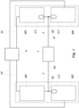
- Fig.1 shows a schematic setup to provide and set a common reference frame between the two receivers 2 and 3.
- the entangled photon source 1 is connected via two transmission channels 10 and 11 with the two receivers 2 and 3.
- Each receiver 2 and 3 comprises two measurement means.
- Receiver 2 comprises measurement means M1 and M2 and receiver 3 comprises the measurement means M3 and M4.
- Each measurement means can measure the photons of the entangled photon source in a specific measurement basis, whereas the bases of the configured setup of the receiver 2 are two mutually unbiased measurement bases B1 and B2, and the measurement bases of the receiver 3 are two mutually unbiased measurement bases B3 and B4.
- the photons in the first transmission channel 10 are randomly guided by a first separation component S1 to the first and second measurement means M1 and M2.
- the photons in the second transmission channel 11 are randomly guided by a second separation component S2 to the third and fourth measurement means M3 and M4.
- three correction means C1, C2 and C3 are arranged in three of the four measurement means.
- the correction means C1, C2 and C3 are arranged in the measurement means M2, M3 and M4.
- the correction means C1, C2 and C3 can also be in every other configuration in the measurement means.
- the correction means C1, C2 and C3 can also be in the measurement means M1, M3 and M4, or in the measurement means M1, M2 and M4, or in the measurement means M1, M2 and M3.
- the photons of the entangled photon source 1 are detected and the signal is sent via cables to a coincidence logic 4.
- the time of the arrival of each signal is registered in the coincidence logic 4, taking the distances and different cable lengths into account. From these signals, the visibility (V) and/or the quantum bit error rate (QBER) can be calculated.
- Fig. 2 shows as an example of the invention a setup of an apparatus to provide and set a common polarization reference frame between two receivers with photon pairs entangled in polarization.
- Each measurement means M1, M2, M3 and M4 can measure the photons in at least two orthogonal states.
- the entangled photon source 1 produces photon pairs entangled in polarization.
- the state of the produced entangled photon pair is in this example
- ⁇ ⁇ 1 2
- ⁇ ⁇ 1 2
- ⁇ as the states of the entangled photon pairs,
- each measurement means M1, M2, M3, and M4 a polarizing beam splitter 12 and two detectors 13. With that, each measurement means M1, M2, M3 and M4 can measure the photons in at least two orthogonal states.
- the first, second and third correction means C1, C2 and C3 are arranged.
- the correction means C1, C2 comprise a quarter wave-, half wave- and quarter wave-plate, and/or a variable wave-plate, and/or a tilted wave-plate, and/or a birefringent element, and/or a fiber controller to alter the polarization without measuring the polarization of the photons, and thus to adjust the measurement bases between the measurement means M1, M2, M3 and M4.
- Each detector 13 registers a single photon and generates an electric signal, which is sent via a cable 14 to the coincidence logic 4.
- the photons can be measured in two orthogonal states a in the first detector 13 and b in the second detector 13.
- the visibility (V) and the quantum bit error rate QBER are calculated here for photons detected in the measurement means M1 and M3, where CC M1 ⁇ ,M3 ⁇ denotes the coincidence count rate between the first detector 13 for state a in the measurement means M1, and the first detector 13 for state a in the measurement means M3.
- V M 1 , M 3 CC M 1 a , M 3 a + CC M 1 b , M 3 b ⁇ CC M 1 a , M 3 b ⁇ CC M 1 b , M 3 a CC M 1 a , M 3 a + CC M 1 b , M 3 b + CC M 1 a , M 3 b + CC M 1 b , M 3 a
- QBER M 1 , M 3 1 ⁇ V M 1 , M 3 2
- the coincidence logic 4 can be connected to the first, second and third correction means S1, S2 and S3 (the connection is not shown in Fig. 1 and 2 ) to adjust the common polarization reference frame for a secure key distribution for quantum cryptography.
- the measurement bases of measurement means M1 and M2 have to be mutually unbiased.
- the measurement means M3 and M4 have to have the same measurement bases as the measurement means in M1 and M2. According to the invention, it is not necessary for both receivers 2 and 3 to know the exact measurement bases in which they will measure the photons.
- the steps to configure the setup and to set a common polarization reference frame are:
- the steps described before can be performed in any other order. For example, at first the mutually unbiased polarization bases between the first measurement means M1 and the fourth measurement means M4 can be set, and then the same polarization bases between the first measurement means M1 and the third measurement means M3 and the same polarization bases between the fourth measurement means M4 and the second measurement means M2.
Landscapes
- Engineering & Computer Science (AREA)
- Physics & Mathematics (AREA)
- Electromagnetism (AREA)
- Computer Networks & Wireless Communication (AREA)
- Signal Processing (AREA)
- Optics & Photonics (AREA)
- Theoretical Computer Science (AREA)
- Computer Security & Cryptography (AREA)
- Optical Communication System (AREA)
Claims (14)
- Une méthode pour fournir un cadre de référence commun entre deux récepteurs, de préférence pour la distribution quantique de clés,dans laquelle le premier récepteur (2) est connecté via un premier canal de transmission (10) à une source de photons intriqués (1) et le second récepteur (3) est connecté via un second canal de transmission (11) à la source de photons intriqués (1),dans laquelle la source de photons intriqués (1) produit des paires de photons intriqués, de préférence intriqués dans la polarisation, l'intervalle de temps, le moment angulaire orbital ou la trajectoire,dans laquelle le premier photon de chaque paire de photons intriqués est envoyé via le premier canal de transmission (10) au premier récepteur (2) et le second photon de chaque paire de photons intriqués est envoyé via le second canal de transmission (11) au second récepteur (3),dans laquelle le premier récepteur (2) comprend un premier (M1) et un deuxième (M2) moyens de mesure pour mesurer les photons dans deux bases de mesure mutuellement impartiales,dans laquelle le deuxième récepteur (3) comprend un troisième (M3) et un quatrième (M4) moyens de mesure pour mesurer les photons dans deux bases de mesure mutuellement impartiales,dans laquelle chaque moyen de mesure peut mesurer les photons dans au moins deux états orthogonaux,dans laquelle les quatre moyens de mesure (M1, M2, M3, M4) peuvent communiquer le moment de la détection d'un photon des paires de photons intriqués pour détecter les coïncidences entre les deux récepteurs d'une paire de photons intriqués et pour calculer la visibilité et/ou le taux d'erreur binaire quantique (TEBQ),- dans laquelle trois des quatre moyens de mesure comprennent chacun un moyen de correction (C1, C2, C3) pour établir le cadre de référence commun,- dans laquelle la méthode comprend les étapes suivantesi) minimisation du TEBQ ou maximisation de la visibilité pour les photons détectés dans le premier (M1) et le troisième (M3) moyen de mesure en ajustant le premier moyen de correction (C1) afin de définir les mêmes bases de mesure entre le premier moyen de mesure (M1) et le troisième moyen de mesure (M3),ii) maximisation du TEBQ ou minimisation de la visibilité pour les photons détectés dans le premier (M1) et le quatrième (M4) moyen de mesure en ajustant le deuxième moyen de correction (C2) afin de définir deux bases de mesure mutuellement impartiales entre le premier moyen de mesure (M1) et le quatrième moyen de mesure (M4),iii) minimisation du TEBQ ou maximisation de la visibilité des photons détectés dans le quatrième (M4) et le deuxième (M2) moyen de mesure en ajustant le troisième moyen de correction (C3) afin de définir les mêmes bases de mesure entre le quatrième moyen de mesure (M4) et le deuxième moyen de mesure (M2).
- Méthode selon la revendication 1,
dans laquelle, après l'étape iii), une clé sécurisée entre les deux récepteurs est générée par distribution quantique de clés. - Méthode selon l'une des revendications 1 ou 2,dans laquelle le premier moyen de correction (C1) est affecté au premier (M1) ou au troisième (M3) moyen de mesure, etdans laquelle le deuxième moyen de correction (C2) est affecté au troisième (M3) ou au quatrième (M4) moyen de mesure, etdans laquelle le troisième moyen de correction (C3) est affecté au quatrième (M4) ou au deuxième (M2) moyen de mesure.
- Méthode selon l'une des revendications 1 ou 3,dans laquelle le premier moyen de correction (C1) est disposédans le premier canal de transmission (10) ou dans ou avant le premier moyen de mesure (M1), ou dans le deuxième canal de transmission (11) ou dans ou avant le troisième moyen de mesure (M3), et/oudans laquelle le deuxième moyen de correction (C2) est disposédans le premier canal de transmission (10) ou dans ou avant le premier moyen de mesure (M1), ou dans le deuxième canal de transmission (11) ou dans ou avant le quatrième moyen de mesure (M4), et/oudans laquelle le troisième moyen de correction (C3) est disposédans le deuxième canal de transmission (11) ou dans ou avant le quatrième moyen de mesure (M4), ou dans le premier canal de transmission (10) ou dans ou avant le deuxième moyen de mesure (M2).
- Méthode selon l'une des revendications 1 ou 4,
dans laquelle les paires de photons intriquées peuvent être intriquées au niveau de la polarisation, de l'intervalle de temps, du moment angulaire orbital ou de la trajectoire. - Méthode selon l'une des revendications 1 ou 5,
dans laquelle le premier (10) et/ou le second (11) canal de transmission est/sont un canal en espace libre ou un guide d'ondes, de préférence une fibre. - Méthode selon l'une des revendications 1 ou 6,
dans laquelle le premier (C1), le deuxième (C2) et/ou le troisième (C3) moyen de correction est/sont un ensemble de plaques quart d'onde, demi-onde et quart d'onde, et/ou une plaque d'onde variable, et/ou une plaque d'onde inclinée, et/ou un élément biréfringent, et/ou un trombone et/ou un contrôleur de fibre, ou un modulateur spatial de lumière (SLM), et/ou une ligne à retard. - Méthode selon l'une des revendications 1 ou 7,dans laquelle le photon d'une paire de photons dans le premier canal de transmission (10) est guidé de manière aléatoire vers le premier (M1) ou le deuxième (M2) moyen de mesure par un premier composant de séparation (S1), de préférence un séparateur de faisceau ou un séparateur de faisceau à fibre, ou acheminé de manière aléatoire par un commutateur à fibre,et/ou dans laquelle le photon d'une paire de photons dans le deuxième canal de transmission (11) est guidé de manière aléatoire vers le troisième (M3) ou le quatrième (M4) moyen de mesure par un deuxième composant de séparation (S2), de préférence par un séparateur de faisceau ou un séparateur de faisceau à fibre ou acheminé de manière aléatoire par un commutateur à fibre.
- Méthode selon la revendication 8,dans laquelle le premier moyen de correction (C1) est disposé après ou derrière le premier composant de séparation (S1) dans le premier moyen de mesure (M1) ou est disposé après ou derrière le deuxième composant de séparation (S2) dans le troisième moyen de mesure (M3), etdans laquelle le deuxième moyen de correction (C2) est disposé après ou derrière le deuxième composant de séparation (S2) dans le troisième moyen de mesure (M3) ou est disposé après ou derrière le deuxième composant de séparation (S2) dans le quatrième moyen de mesure (M4), etdans laquelle le troisième moyen de correction (C3) est placé après ou derrière le deuxième composant de séparation (S2) dans le quatrième moyen de mesure (M4) ou est placé après ou derrière le premier composant de séparation (S1) dans le deuxième moyen de mesure (M2).
- Dispositif de contrôle (4), de préférence un ordinateur, capable de fournir une méthode selon l'une des revendications 1 à 9, dans lequel le dispositif de contrôle est connectéavec les premier (M1), deuxième (M2), troisième (M3) et quatrième (M4) moyens de détection afin d'enregistrer les photons détectés et les coïncidences des paires de photons intriqués et de calculer la visibilité et/ou le taux d'erreur binaire quantique des photons détectés, etavec le premier (C1), le deuxième (C2) et le troisième (C3) moyens de correction afin d'établir le cadre de référence commun entre les deux récepteurs (2, 3).
- Dispositif informatique en tant que dispositif de contrôle selon la revendication 10 avec un microprocesseur avec une mémoire non volatile, dans lequel la mémoire non volatile comprend un programme exécutable afin de fournir une méthode selon l'une des revendications 1 à 9.
- Système pour fournir un cadre de référence commun entre deux récepteurs, de préférence pour la distribution quantique de clés,dans lequel le système comprend une source de photons intriqués (1), un premier récepteur (2) et un second récepteur (3), ainsi qu'un premier canal de transmission (10) et un second canal de transmission (20),dans lequel le premier récepteur (2) est connecté via le premier canal de transmission (10) à une source de photons intriqués (1) et le second récepteur (3) est connecté via le second canal de transmission (11) à la source de photons intriqués (1),dans lequel la source de photons intriqués (1) produit des paires de photons intriqués, de préférence intriqués dans la polarisation, l'intervalle de temps, le moment angulaire orbital ou la trajectoire,dans lequel le premier photon de chaque paire de photons intriqués est envoyé via le premier canal de transmission (10) au premier récepteur (2) et le second photon de chaque paire de photons intriqués est envoyé via le second canal de transmission (11) au second récepteur (3),dans lequel le premier récepteur (2) comprend un premier (M1) et un deuxième (M2) moyens de mesure pour mesurer les photons dans deux bases de mesure mutuellement impartiales,dans lequel le deuxième récepteur (3) comprend un troisième (M3) et un quatrième (M4) moyens de mesure pour mesurer les photons dans deux bases de mesure mutuellement impartiales,dans lequel chaque moyen de mesure peut mesurer les photons dans au moins deux états orthogonaux,dans lequel les quatre moyens de mesure (M1, M2, M3, M4) peuvent communiquer le moment de la détection d'un photon des paires de photons intriqués pour détecter les coïncidences entre les deux récepteurs d'une paire de photons intriqués et pour calculer la visibilité et/ou le taux d'erreur binaire quantique (TEBQ),caractérisé en ce que trois des quatre moyens de mesure comprennent chacun un moyen de correction (C1, C2, C3) pour établir le cadre de référence commun adapté à la réalisation des étapes i) à iii) selon l'une des revendications 1 à 11.
- Système selon la revendication 12,dans lequel, dans le premier canal de transmission (10), un premier composant de séparation (S1), de préférence un séparateur de faisceau ou un séparateur de faisceau à fibre, est disposé pour guider de manière aléatoire un photon vers le premier (M1) ou le deuxième (M2) moyen de mesure, et/oudans lequel, dans le deuxième canal de transmission (11), un deuxième composant de séparation (S2), de préférence un séparateur de faisceau ou un séparateur de faisceau à fibre, est disposé pour guider de manière aléatoire un photon vers le troisième (M3) ou le quatrième (M4) moyen de mesure.
- Système selon la revendication 13,dans lequel le premier moyen de correction (C1) est disposé après ou derrière le premier composant de séparation (S1) dans le premier moyen de mesure (M1) ou est disposé après ou derrière le deuxième composant de séparation (S2) dans le troisième moyen de mesure (M3), etdans lequel le deuxième moyen de correction (C2) est disposé après ou derrière le deuxième composant de séparation (S2) dans le troisième moyen de mesure (M3) ou est disposé après ou derrière le deuxième composant de séparation (S2) dans le quatrième moyen de mesure (M4), etdans lequel le troisième moyen de correction (C3) est placé après ou derrière le deuxième composant de séparation (S2) dans le quatrième moyen de mesure (M4) ou est placé après ou derrière le premier composant de séparation (S1) dans le deuxième moyen de mesure (M2).
Applications Claiming Priority (2)
| Application Number | Priority Date | Filing Date | Title |
|---|---|---|---|
| EP19188171.3A EP3771137A1 (fr) | 2019-07-24 | 2019-07-24 | Procédé de fourniture d'un cadre de référence commun entre deux récepteurs |
| PCT/EP2020/070955 WO2021013990A1 (fr) | 2019-07-24 | 2020-07-24 | Procédé pour fournir un cadre de référence commun entre deux récepteurs |
Publications (3)
| Publication Number | Publication Date |
|---|---|
| EP4005145A1 EP4005145A1 (fr) | 2022-06-01 |
| EP4005145B1 true EP4005145B1 (fr) | 2024-09-04 |
| EP4005145C0 EP4005145C0 (fr) | 2024-09-04 |
Family
ID=67438761
Family Applications (2)
| Application Number | Title | Priority Date | Filing Date |
|---|---|---|---|
| EP19188171.3A Withdrawn EP3771137A1 (fr) | 2019-07-24 | 2019-07-24 | Procédé de fourniture d'un cadre de référence commun entre deux récepteurs |
| EP20742765.9A Active EP4005145B1 (fr) | 2019-07-24 | 2020-07-24 | Procédé de fourniture d'un cadre de référence commun entre deux récepteurs |
Family Applications Before (1)
| Application Number | Title | Priority Date | Filing Date |
|---|---|---|---|
| EP19188171.3A Withdrawn EP3771137A1 (fr) | 2019-07-24 | 2019-07-24 | Procédé de fourniture d'un cadre de référence commun entre deux récepteurs |
Country Status (3)
| Country | Link |
|---|---|
| EP (2) | EP3771137A1 (fr) |
| ES (1) | ES2992489T3 (fr) |
| WO (1) | WO2021013990A1 (fr) |
Families Citing this family (10)
| Publication number | Priority date | Publication date | Assignee | Title |
|---|---|---|---|---|
| US12039409B2 (en) | 2020-05-05 | 2024-07-16 | Qubit Moving And Storage, Llc | Quantum information system and method with entanglement tracking and generation of verified quantum information using metadata |
| US11962353B2 (en) | 2022-04-06 | 2024-04-16 | Qubit Moving And Storage, Llc | Method and system for identifying entangled photons with one-way classical information sharing |
| US11614771B2 (en) | 2020-11-25 | 2023-03-28 | Qubit Moving And Storage, Llc | Method for synchronizing and locking clocks |
| US11367014B2 (en) | 2020-05-05 | 2022-06-21 | Qubit Moving And Storage, Llc | System and method for quantum cache |
| US12003626B2 (en) | 2020-11-25 | 2024-06-04 | Qubit Moving And Storage, Llc | System and method of verification, authentication, and/or certification using entangled photons |
| US11616644B2 (en) | 2020-11-25 | 2023-03-28 | Qubit Moving And Storage, Llc | System and method of verification and authentication using entangled photons |
| US11411658B1 (en) | 2021-12-14 | 2022-08-09 | Qubit Moving And Storage, Llc | Entangled quantum state receiver |
| US11933608B2 (en) | 2022-05-19 | 2024-03-19 | Qubit Moving And Storage, Llc | Quantum interferometer with improved entangled photon identification |
| US12007272B2 (en) | 2022-10-15 | 2024-06-11 | Qubit Moving And Storage, Llc | Entangled photon identification system and method for quantum optical measurement |
| DE102023104245B3 (de) * | 2023-02-21 | 2024-06-27 | Quantum Optics Jena GmbH | Verfahren und System zur Schlüsselerzeugung mit Quantenschlüsselaustausch, sowie Verfahren zur Datenübertragung |
Family Cites Families (3)
| Publication number | Priority date | Publication date | Assignee | Title |
|---|---|---|---|---|
| US6424665B1 (en) | 1999-04-30 | 2002-07-23 | The Regents Of The University Of California | Ultra-bright source of polarization-entangled photons |
| US6897434B1 (en) | 2002-02-28 | 2005-05-24 | Northwestern University | All-fiber photon-pair source for quantum communications |
| GB2419264B (en) * | 2003-08-18 | 2006-12-27 | Toshiba Res Europ Ltd | A quantum communication system and a receiver for a quantum communication system |
-
2019
- 2019-07-24 EP EP19188171.3A patent/EP3771137A1/fr not_active Withdrawn
-
2020
- 2020-07-24 ES ES20742765T patent/ES2992489T3/es active Active
- 2020-07-24 EP EP20742765.9A patent/EP4005145B1/fr active Active
- 2020-07-24 WO PCT/EP2020/070955 patent/WO2021013990A1/fr not_active Ceased
Also Published As
| Publication number | Publication date |
|---|---|
| EP4005145A1 (fr) | 2022-06-01 |
| EP3771137A1 (fr) | 2021-01-27 |
| WO2021013990A1 (fr) | 2021-01-28 |
| EP4005145C0 (fr) | 2024-09-04 |
| ES2992489T3 (es) | 2024-12-13 |
Similar Documents
| Publication | Publication Date | Title |
|---|---|---|
| EP3771137A1 (fr) | Procédé de fourniture d'un cadre de référence commun entre deux récepteurs | |
| Amer et al. | An introduction to practical quantum key distribution | |
| US8374350B2 (en) | Quantum communication system | |
| JP6303034B2 (ja) | 通信システムおよび方法 | |
| US8171354B2 (en) | Communication system and method for controlling the same | |
| EP2949072B1 (fr) | Système de distribution de clé cryptographique quantique comprenant deux dispositifs périphériques et une source optique | |
| EP1742408B1 (fr) | Système de communication et méthode de commande de synchronisation | |
| KR20190053837A (ko) | 위상 편광 다 자유도 변조 양자키분배 네트워크 시스템 및 방법 | |
| WO2024121850A1 (fr) | Communication optique spatiale sans distribution de clé quantique | |
| CA2883444A1 (fr) | Systeme et procede de cryptographie quantique | |
| US20050100351A1 (en) | Quantum communication system and a receiver for a quantum communication system | |
| US12362925B2 (en) | Method for remote generation of two arbitrary-length identical random cryptographic keys with the device-independent security using entangled multi- photon sources of quantum light | |
| WO2006074151A2 (fr) | Utilisation securisee d'un detecteur de photon unique dans un systeme de distribution quantique de cle | |
| Rani et al. | Combined quantum and post-quantum security for Earth-satellite channels | |
| EP4062580B1 (fr) | Appareil, système et procédé de décodage de bits quantiques | |
| Kebapci et al. | Real-time implementation of an underwater quantum key distribution system | |
| Mantey et al. | Frame synchronization for quantum key distribution systems | |
| EP4005115B1 (fr) | Procédé pour définir un cadre de référence de polarisation commun | |
| GB2441364A (en) | A quantum communication system which selects different protocols on the basis of security | |
| EP4742560A1 (fr) | Dispositif, système et procédé de correction automatique de polarisation de photons dans des systèmes de distribution de clé quantique | |
| JP2024075947A (ja) | 量子鍵配送システム及び量子鍵配送方法 | |
| EA052235B1 (ru) | Система квантовой криптографии на запутанных поляризационных состояниях фотонов с активным выбором базиса измерения | |
| WO2026013107A1 (fr) | Système de mise en correspondance de mode de signal pour configurations de distribution de clé quantique | |
| CN110351071A (zh) | 一种发射端无需干涉环的量子密钥分发系统及方法 | |
| Pillay et al. | Compensating birefringence effects in optical fibre for polarisation encoded QKD |
Legal Events
| Date | Code | Title | Description |
|---|---|---|---|
| STAA | Information on the status of an ep patent application or granted ep patent |
Free format text: STATUS: UNKNOWN |
|
| STAA | Information on the status of an ep patent application or granted ep patent |
Free format text: STATUS: THE INTERNATIONAL PUBLICATION HAS BEEN MADE |
|
| PUAI | Public reference made under article 153(3) epc to a published international application that has entered the european phase |
Free format text: ORIGINAL CODE: 0009012 |
|
| STAA | Information on the status of an ep patent application or granted ep patent |
Free format text: STATUS: REQUEST FOR EXAMINATION WAS MADE |
|
| 17P | Request for examination filed |
Effective date: 20220201 |
|
| AK | Designated contracting states |
Kind code of ref document: A1 Designated state(s): AL AT BE BG CH CY CZ DE DK EE ES FI FR GB GR HR HU IE IS IT LI LT LU LV MC MK MT NL NO PL PT RO RS SE SI SK SM TR |
|
| DAV | Request for validation of the european patent (deleted) | ||
| DAX | Request for extension of the european patent (deleted) | ||
| GRAP | Despatch of communication of intention to grant a patent |
Free format text: ORIGINAL CODE: EPIDOSNIGR1 |
|
| STAA | Information on the status of an ep patent application or granted ep patent |
Free format text: STATUS: GRANT OF PATENT IS INTENDED |
|
| INTG | Intention to grant announced |
Effective date: 20240522 |
|
| GRAS | Grant fee paid |
Free format text: ORIGINAL CODE: EPIDOSNIGR3 |
|
| GRAA | (expected) grant |
Free format text: ORIGINAL CODE: 0009210 |
|
| STAA | Information on the status of an ep patent application or granted ep patent |
Free format text: STATUS: THE PATENT HAS BEEN GRANTED |
|
| AK | Designated contracting states |
Kind code of ref document: B1 Designated state(s): AL AT BE BG CH CY CZ DE DK EE ES FI FR GB GR HR HU IE IS IT LI LT LU LV MC MK MT NL NO PL PT RO RS SE SI SK SM TR |
|
| REG | Reference to a national code |
Ref country code: GB Ref legal event code: FG4D |
|
| REG | Reference to a national code |
Ref country code: CH Ref legal event code: EP |
|
| REG | Reference to a national code |
Ref country code: IE Ref legal event code: FG4D |
|
| REG | Reference to a national code |
Ref country code: DE Ref legal event code: R096 Ref document number: 602020037091 Country of ref document: DE |
|
| U01 | Request for unitary effect filed |
Effective date: 20240913 |
|
| U07 | Unitary effect registered |
Designated state(s): AT BE BG DE DK EE FI FR IT LT LU LV MT NL PT RO SE SI Effective date: 20241004 |
|
| REG | Reference to a national code |
Ref country code: ES Ref legal event code: FG2A Ref document number: 2992489 Country of ref document: ES Kind code of ref document: T3 Effective date: 20241213 |
|
| PG25 | Lapsed in a contracting state [announced via postgrant information from national office to epo] |
Ref country code: NO Free format text: LAPSE BECAUSE OF FAILURE TO SUBMIT A TRANSLATION OF THE DESCRIPTION OR TO PAY THE FEE WITHIN THE PRESCRIBED TIME-LIMIT Effective date: 20241204 |
|
| PG25 | Lapsed in a contracting state [announced via postgrant information from national office to epo] |
Ref country code: PL Free format text: LAPSE BECAUSE OF FAILURE TO SUBMIT A TRANSLATION OF THE DESCRIPTION OR TO PAY THE FEE WITHIN THE PRESCRIBED TIME-LIMIT Effective date: 20240904 Ref country code: GR Free format text: LAPSE BECAUSE OF FAILURE TO SUBMIT A TRANSLATION OF THE DESCRIPTION OR TO PAY THE FEE WITHIN THE PRESCRIBED TIME-LIMIT Effective date: 20241205 |
|
| PG25 | Lapsed in a contracting state [announced via postgrant information from national office to epo] |
Ref country code: HR Free format text: LAPSE BECAUSE OF FAILURE TO SUBMIT A TRANSLATION OF THE DESCRIPTION OR TO PAY THE FEE WITHIN THE PRESCRIBED TIME-LIMIT Effective date: 20240904 |
|
| PG25 | Lapsed in a contracting state [announced via postgrant information from national office to epo] |
Ref country code: RS Free format text: LAPSE BECAUSE OF FAILURE TO SUBMIT A TRANSLATION OF THE DESCRIPTION OR TO PAY THE FEE WITHIN THE PRESCRIBED TIME-LIMIT Effective date: 20241204 |
|
| PG25 | Lapsed in a contracting state [announced via postgrant information from national office to epo] |
Ref country code: RS Free format text: LAPSE BECAUSE OF FAILURE TO SUBMIT A TRANSLATION OF THE DESCRIPTION OR TO PAY THE FEE WITHIN THE PRESCRIBED TIME-LIMIT Effective date: 20241204 Ref country code: PL Free format text: LAPSE BECAUSE OF FAILURE TO SUBMIT A TRANSLATION OF THE DESCRIPTION OR TO PAY THE FEE WITHIN THE PRESCRIBED TIME-LIMIT Effective date: 20240904 Ref country code: NO Free format text: LAPSE BECAUSE OF FAILURE TO SUBMIT A TRANSLATION OF THE DESCRIPTION OR TO PAY THE FEE WITHIN THE PRESCRIBED TIME-LIMIT Effective date: 20241204 Ref country code: HR Free format text: LAPSE BECAUSE OF FAILURE TO SUBMIT A TRANSLATION OF THE DESCRIPTION OR TO PAY THE FEE WITHIN THE PRESCRIBED TIME-LIMIT Effective date: 20240904 Ref country code: GR Free format text: LAPSE BECAUSE OF FAILURE TO SUBMIT A TRANSLATION OF THE DESCRIPTION OR TO PAY THE FEE WITHIN THE PRESCRIBED TIME-LIMIT Effective date: 20241205 |
|
| PG25 | Lapsed in a contracting state [announced via postgrant information from national office to epo] |
Ref country code: IS Free format text: LAPSE BECAUSE OF FAILURE TO SUBMIT A TRANSLATION OF THE DESCRIPTION OR TO PAY THE FEE WITHIN THE PRESCRIBED TIME-LIMIT Effective date: 20250104 |
|
| PG25 | Lapsed in a contracting state [announced via postgrant information from national office to epo] |
Ref country code: SM Free format text: LAPSE BECAUSE OF FAILURE TO SUBMIT A TRANSLATION OF THE DESCRIPTION OR TO PAY THE FEE WITHIN THE PRESCRIBED TIME-LIMIT Effective date: 20240904 |
|
| PG25 | Lapsed in a contracting state [announced via postgrant information from national office to epo] |
Ref country code: CZ Free format text: LAPSE BECAUSE OF FAILURE TO SUBMIT A TRANSLATION OF THE DESCRIPTION OR TO PAY THE FEE WITHIN THE PRESCRIBED TIME-LIMIT Effective date: 20240904 |
|
| PG25 | Lapsed in a contracting state [announced via postgrant information from national office to epo] |
Ref country code: SK Free format text: LAPSE BECAUSE OF FAILURE TO SUBMIT A TRANSLATION OF THE DESCRIPTION OR TO PAY THE FEE WITHIN THE PRESCRIBED TIME-LIMIT Effective date: 20240904 |
|
| U20 | Renewal fee for the european patent with unitary effect paid |
Year of fee payment: 6 Effective date: 20250520 |
|
| PLBE | No opposition filed within time limit |
Free format text: ORIGINAL CODE: 0009261 |
|
| STAA | Information on the status of an ep patent application or granted ep patent |
Free format text: STATUS: NO OPPOSITION FILED WITHIN TIME LIMIT |
|
| 26N | No opposition filed |
Effective date: 20250605 |
|
| PGFP | Annual fee paid to national office [announced via postgrant information from national office to epo] |
Ref country code: ES Payment date: 20250819 Year of fee payment: 6 |
|
| PGFP | Annual fee paid to national office [announced via postgrant information from national office to epo] |
Ref country code: GB Payment date: 20250724 Year of fee payment: 6 |
|
| REG | Reference to a national code |
Ref country code: CH Ref legal event code: H13 Free format text: ST27 STATUS EVENT CODE: U-0-0-H10-H13 (AS PROVIDED BY THE NATIONAL OFFICE) Effective date: 20260224 |
|
| PG25 | Lapsed in a contracting state [announced via postgrant information from national office to epo] |
Ref country code: CH Free format text: LAPSE BECAUSE OF NON-PAYMENT OF DUE FEES Effective date: 20250731 |
|
| PG25 | Lapsed in a contracting state [announced via postgrant information from national office to epo] |
Ref country code: IE Free format text: LAPSE BECAUSE OF NON-PAYMENT OF DUE FEES Effective date: 20250724 |
|
| PG25 | Lapsed in a contracting state [announced via postgrant information from national office to epo] |
Ref country code: MC Free format text: LAPSE BECAUSE OF FAILURE TO SUBMIT A TRANSLATION OF THE DESCRIPTION OR TO PAY THE FEE WITHIN THE PRESCRIBED TIME-LIMIT Effective date: 20240904 |
|
| U20 | Renewal fee for the european patent with unitary effect paid |
Year of fee payment: 7 Effective date: 20260615 |
|
| PG25 | Lapsed in a contracting state [announced via postgrant information from national office to epo] |
Ref country code: CY Free format text: LAPSE BECAUSE OF FAILURE TO SUBMIT A TRANSLATION OF THE DESCRIPTION OR TO PAY THE FEE WITHIN THE PRESCRIBED TIME-LIMIT Effective date: 20240904 |