EP4005268B1 - Präambel mit detektierbarer wlan-versionserkennung - Google Patents
Präambel mit detektierbarer wlan-versionserkennung Download PDFInfo
- Publication number
- EP4005268B1 EP4005268B1 EP20851164.2A EP20851164A EP4005268B1 EP 4005268 B1 EP4005268 B1 EP 4005268B1 EP 20851164 A EP20851164 A EP 20851164A EP 4005268 B1 EP4005268 B1 EP 4005268B1
- Authority
- EP
- European Patent Office
- Prior art keywords
- sig
- version
- identifier
- wireless communication
- field
- Prior art date
- Legal status (The legal status is an assumption and is not a legal conclusion. Google has not performed a legal analysis and makes no representation as to the accuracy of the status listed.)
- Active
Links
Images












Classifications
-
- H—ELECTRICITY
- H04—ELECTRIC COMMUNICATION TECHNIQUE
- H04W—WIRELESS COMMUNICATION NETWORKS
- H04W28/00—Network traffic management; Network resource management
- H04W28/02—Traffic management, e.g. flow control or congestion control
- H04W28/06—Optimizing the usage of the radio link, e.g. header compression, information sizing, discarding information
-
- H—ELECTRICITY
- H04—ELECTRIC COMMUNICATION TECHNIQUE
- H04L—TRANSMISSION OF DIGITAL INFORMATION, e.g. TELEGRAPHIC COMMUNICATION
- H04L1/00—Arrangements for detecting or preventing errors in the information received
- H04L1/004—Arrangements for detecting or preventing errors in the information received by using forward error control
- H04L1/0056—Systems characterized by the type of code used
- H04L1/0057—Block codes
-
- H—ELECTRICITY
- H04—ELECTRIC COMMUNICATION TECHNIQUE
- H04L—TRANSMISSION OF DIGITAL INFORMATION, e.g. TELEGRAPHIC COMMUNICATION
- H04L1/00—Arrangements for detecting or preventing errors in the information received
- H04L1/004—Arrangements for detecting or preventing errors in the information received by using forward error control
- H04L1/0056—Systems characterized by the type of code used
- H04L1/0059—Convolutional codes
-
- H—ELECTRICITY
- H04—ELECTRIC COMMUNICATION TECHNIQUE
- H04L—TRANSMISSION OF DIGITAL INFORMATION, e.g. TELEGRAPHIC COMMUNICATION
- H04L1/00—Arrangements for detecting or preventing errors in the information received
- H04L1/004—Arrangements for detecting or preventing errors in the information received by using forward error control
- H04L1/0056—Systems characterized by the type of code used
- H04L1/0061—Error detection codes
-
- H—ELECTRICITY
- H04—ELECTRIC COMMUNICATION TECHNIQUE
- H04L—TRANSMISSION OF DIGITAL INFORMATION, e.g. TELEGRAPHIC COMMUNICATION
- H04L1/00—Arrangements for detecting or preventing errors in the information received
- H04L1/004—Arrangements for detecting or preventing errors in the information received by using forward error control
- H04L1/0056—Systems characterized by the type of code used
- H04L1/0071—Use of interleaving
-
- H—ELECTRICITY
- H04—ELECTRIC COMMUNICATION TECHNIQUE
- H04L—TRANSMISSION OF DIGITAL INFORMATION, e.g. TELEGRAPHIC COMMUNICATION
- H04L1/00—Arrangements for detecting or preventing errors in the information received
- H04L1/004—Arrangements for detecting or preventing errors in the information received by using forward error control
- H04L1/0072—Error control for data other than payload data, e.g. control data
-
- H—ELECTRICITY
- H04—ELECTRIC COMMUNICATION TECHNIQUE
- H04L—TRANSMISSION OF DIGITAL INFORMATION, e.g. TELEGRAPHIC COMMUNICATION
- H04L1/00—Arrangements for detecting or preventing errors in the information received
- H04L1/08—Arrangements for detecting or preventing errors in the information received by repeating transmission, e.g. Verdan system
-
- H—ELECTRICITY
- H04—ELECTRIC COMMUNICATION TECHNIQUE
- H04L—TRANSMISSION OF DIGITAL INFORMATION, e.g. TELEGRAPHIC COMMUNICATION
- H04L27/00—Modulated-carrier systems
- H04L27/18—Phase-modulated carrier systems, i.e. using phase-shift keying
-
- H—ELECTRICITY
- H04—ELECTRIC COMMUNICATION TECHNIQUE
- H04L—TRANSMISSION OF DIGITAL INFORMATION, e.g. TELEGRAPHIC COMMUNICATION
- H04L27/00—Modulated-carrier systems
- H04L27/26—Systems using multi-frequency codes
- H04L27/2601—Multicarrier modulation systems
- H04L27/2602—Signal structure
- H04L27/2603—Signal structure ensuring backward compatibility with legacy system
-
- H—ELECTRICITY
- H04—ELECTRIC COMMUNICATION TECHNIQUE
- H04L—TRANSMISSION OF DIGITAL INFORMATION, e.g. TELEGRAPHIC COMMUNICATION
- H04L27/00—Modulated-carrier systems
- H04L27/26—Systems using multi-frequency codes
- H04L27/2601—Multicarrier modulation systems
- H04L27/2602—Signal structure
- H04L27/261—Details of reference signals
- H04L27/2613—Structure of the reference signals
- H04L27/26136—Pilot sequence conveying additional information
-
- H—ELECTRICITY
- H04—ELECTRIC COMMUNICATION TECHNIQUE
- H04W—WIRELESS COMMUNICATION NETWORKS
- H04W48/00—Access restriction; Network selection; Access point selection
- H04W48/08—Access restriction or access information delivery, e.g. discovery data delivery
-
- H—ELECTRICITY
- H04—ELECTRIC COMMUNICATION TECHNIQUE
- H04W—WIRELESS COMMUNICATION NETWORKS
- H04W84/00—Network topologies
- H04W84/02—Hierarchically pre-organised networks, e.g. paging networks, cellular networks, WLAN [Wireless Local Area Network] or WLL [Wireless Local Loop]
- H04W84/10—Small scale networks; Flat hierarchical networks
- H04W84/12—WLAN [Wireless Local Area Networks]
Definitions
- This disclosure generally relates to wireless communications, and the invention in particular relates to devices, methods, and computer-readable media for detecting a wireless local area network (WLAN) physical layer (PHY) version of a transmission.
- WLAN wireless local area network
- PHY physical layer
- the Institute of Electrical and Electronics Engineers sets standards for wireless communication technologies, including wireless local area network (WLAN) communication technologies.
- WLAN wireless local area network
- the IEEE 802.11 family of standards relate to WLANs and their quality of service (QoS), access point protocol, security enhancement, wireless management, etc.
- QoS quality of service
- access point protocol access point protocol
- security enhancement security enhancement
- wireless management etc.
- IEEE 802.11a There are different wireless network versions of IEEE 802.11.
- the versions include 802.11a, 802.11g (Extended Rate Physical Layer (PHY), ERP), 802.11n (High Throughput, HT), 802.11ac (Very High Throughput, VHT), and 802.11ax (High Efficiency, HE).
- IEEE 802.11be also known as Extremely High Throughput, EHT.
- IEEE 802.11be has a target of maximum throughput of 30 Gigabits per second (Gbps) with carrier frequency operation between 1 and 7.250 GigaHertz (GHz) while ensuring backward compatibility and coexistence with legacy IEEE 802.11 compliant devices operating in the 2.4 GHz, 5 GHz, and 6 GHz bands.
- Gbps Gigabits per second
- GHz GigaHertz
- a wireless communication device is required to know which version of IEEE 802.11 is being used in a communication frame so as to properly interpret or respond to the communication frame.
- the device can also benefit from knowing what type of frame is being communicated.
- the frame needs to be compatible with legacy versions along with current versions of IEEE 802.11.
- the object of the present invention is to provide devices, methods and computer readable media which can provide a solution for efficient, backward-compatible, low-error and robust detection of the particular WLAN PHY version of a communication to provide a communication format that indicates the type of frame being communicated.
- Example embodiments relate to a control signal that enables automatic wireless LAN PHY version detection of a transmission, so that the wireless LAN PHY version can be used for interpreting the control signal and the transmission.
- the control signal is within a preamble of the transmission.
- the wireless LAN PHY version can be an IEEE 802.11 version, such as proposed IEEE 802.11be.
- the control signal is compatible with legacy systems and can indicate the legacy signaling information by way of a Legacy Signal (SIG) (L-SIG) field.
- SIG Legacy Signal
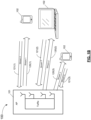
- FIG. 1A provides an example schematic diagram of a wireless communication system 100 in which example embodiments may be implemented.
- the wireless communication system 100 includes an access point (AP, also known as an AP STA or a network coordinator) 101 and at least one station (STA, also known as non-AP STA) 102 in a wireless communication network, such as a wireless local area network (WLAN).
- the AP 101 is any entity that has STA functionality and provides access to the Internet or a distribution service for the associated STAs 102.
- the STAs 102 may be mobile communication devices enabled for wireless communications, including but not limited to mobile phones, smart phones, laptops, tablet computers, machine-type communication devices, Internet of Things (IoT) devices, and wireless sensing and reporting devices.
- the AP 101 and the STAs 102 can each be configured to execute uplink (UL) and downlink (DL) transmissions in the WLAN.
- UL uplink
- DL downlink
- the wireless communication system 100 supports multi-user multiple input multiple output (MU-MIMO) transmissions, also known as a multiple access transmissions.
- MU-MIMO multi-user multiple input multiple output
- the AP 101 and at least one of the STAs 102 may be configured for single user (SU) communications in other examples (not shown here).
- SU single user
- MU-MIMO based transmission which can use multiple antennas, allows simultaneous channel access by the STAs 102 for effective use of frequency channels in the WLAN.
- the AP 101 can simultaneously transmit spatial-multiplexed data to the STAs 102.
- Payload data can be simultaneously transmitted by the AP 101 to the STAs 102 using a plurality of respective spatial streams (stream 1, 2, 3 shown in Figure 1B ) in the DL direction, shown as DL MU transmissions 120(1) to 120(3) (generically referred to as DL MU transmission 120).
- DL MU transmissions 120(1) to 120(3) (generically referred to as DL MU transmission 120).
- DL MU transmission 120 In the DL direction, payload data transmitted to each STA 102 may be different for each STA 102.
- payload data transmitted to the AP 101 In the UL direction, payload data can be simultaneously transmitted to the AP 101 using a plurality of respective spatial streams (stream 4, 5, 6 shown in Figure 1B ), shown as UL MU transmissions 121(1) to 121(3) (generically referred to as UL MU transmission 121).
- the DL MU transmissions 120 and the UL MU transmissions 121 are payload transmissions.
- the DL MU transmissions 120 and the UL MU transmissions 121 may use Orthogonal Frequency Division Multiple Access (OFDMA), with MU-MIMO or without MU-MIMO.
- OFDMA Orthogonal Frequency Division Multiple Access
- FIG. 2 illustrates an OFDMA transmission scheme to multiplex communications with a plurality of STAs 102 over different frequencies (f) and times (t).
- the OFDMA is a multiple access scheme where different subsets of sub-carriers are allocated to different STAs 102, allowing the AP 101 to have data communication with the different STAs 102 (e.g., STAs 102(1) to 102(4) as shown in Figure 2 ).
- the STAs 102 can have data transmission scheduled across both frequency (such as sub-carriers 200(1) to 200(n) (generically referred to as sub-carrier 200) and time.
- a Resource Unit (RU) 201 includes a plurality of sub-carriers, typically with a minimum size of 26 sub-carriers 200.
- the RU 201 has a maximum number of sub-carriers that can be used by one or more of the STAs 102.
- the AP 101 can assign each STA 102 one or more RUs in order to perform a UL or DL transmission, or can assign multiple STAs 102 to a RU.
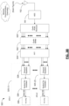
- Figure 3A illustrates a transmitter 310 and Figure 3B illustrates a receiver 320, in accordance with example embodiments.
- the transmitter 310 is configured to encode the preamble and payload data of the PPDU, and then transmit the PPDU.
- the receiver 320 is configured to receive the PPDU, as applicable.
- the receiver 320 first decodes part of the preamble of the received UL or DL PPDU in order to determine a wireless LAN PHY version of the PPDU, and then the receiver 320 is configured to interpret the preamble and the payload according to the determined wireless LAN PHY version.
- the transmitter 310 and the receiver 320 are used to communicate trigger frames in order to solicit the UL PPDU.
- the transmitter 310 is configured to transmit PPDU.
- the transmitter 310 may be included within the AP 101 or the STA 102 to implement the DL or UL transmission, respectively.
- the transmitter 310 may be included within the AP 101 to transmit PPDU containing a preamble and respective payload data to STAs 102 on their respective sub-carriers in one or more RUs.
- the transmitter 310 may be included within an associated STA 102 to transmit preamble and payload data of the STA 102 on its respective sub-carriers in one or more RUs.
- the transmitter 310 includes a plurality of transmitting (Tx) paths 311(1) to 311(Z) (generically referred to as Tx path 311) for a transmission that includes a preamble and payload data.
- Tx path 311 transmitting path 311(1) to 311(Z)
- the AP 101 can generate Tx paths 311 for different respective STAs (e.g., STA 1 to STA Z).
- the symbol modulator 312 performs symbol modulation on the bits of the payload data to data symbols (also known as a constellation symbols).
- the data symbols can be represented as amplitude and phase, or cosine and sine coefficients, or other nomenclatures, as is understood in the art.
- Each data symbol may be referred to as a chip.
- the symbol modulation can be based on symbol modulation schemes such as amplitude-shift keying (ASK), phase-shift keying (PSK), binary PSK (BPSK), quadrature PSK (QPSK), quadrature amplitude modulation (QAM), or any other appropriate method of mapping series of data bits to a modulated symbol.
- symbol modulation schemes such as amplitude-shift keying (ASK), phase-shift keying (PSK), binary PSK (BPSK), quadrature PSK (QPSK), quadrature amplitude modulation (QAM), or any other appropriate method of mapping series of data bits to a modulated symbol.
- the QAM constellations can be specified by cosine and sine coefficients in quadrature.
- the tone mapping block 314 maps or assigns each data symbol to one or more of the sub-carriers, known as tone mapping.
- the data symbols are provided to the Inverse Fast Fourier Transform (IFFT) block 315 to transform the data symbols to the assigned sub-carriers in time domain. Other types of inverse Fourier transforms can be performed in other examples.
- the output from the IFFT block 315 are OFDMA waveforms in time domain, in parallel for each STA.
- the cyclic prefix generator 316 adds a cyclic prefix to the OFDMA waveforms.
- the parallel to serial converter (P/S) 317 converts the parallel OFDMA waveforms of multiple STAs into a serial digital signal.
- the serial digital signal is converted by a digital-to-analog converter 318 to an analog signal, which is transmitted via an antenna 152.
- the transmission that is transmitted via the antenna 152 can include the preamble (which can have one or more coded/modulated fields as described in greater detail herein) and the coded/modulated data.
- FIG. 3B illustrates a receiver 320 for demodulating each received OFDMA signal in accordance with an example embodiment.
- the receiver 320 may be included within each STA 102 to decode the received OFDMA signal from the DL transmission of the AP 101.
- the receiver 320 may be included within the AP 101 to decode received OFDMA signals from the UL transmission of the STAs 102.
- the receiver 320 includes an antenna 152, an analog-to digital converter (ADC) 322, a cyclic prefix removal block 323, a fast fourier transform (FFT) block 324, and rea plurality of receiving (Rx) paths 325(1) to 325(Z) (generically referred to as Rx path 325) on which data is received and the desired data is recovered.
- ADC analog-to digital converter
- FFT fast fourier transform
- Rx path 325 rea plurality of receiving paths 325(1) to 325(Z)
- the antenna 152 of the receiver 320 receives analog signals from wireless communication frequency channels, such as from the transmitter 310 as shown in Figure 3A .
- the ADC 322 converts each received analog signal into a digital signal.
- the cyclic prefix removal block 323 removes a cyclic prefix from the digital signal.
- the FFT block 324 then transforms the cyclic prefix removed digital signal in time domain into data symbols.
- the data symbols for each STA 102 from the FFT block 324 are processed on a respective one of the plurality of Rx paths. For clarity, one Rx path 325(1) is indicated by a dashed box. One Rx path 325 will now be described in detail.
- Data symbols are provided to a channel equalizer 326 for equalization, which may help to reduce inter-symbol interference (ISI) and noise effects for better demodulation.
- the equalized data symbols from the channel equalizer 326 are input to the symbol demodulator 328.
- the symbol demodulator 328 uses symbol demodulation to demodulate the data symbols into series of bits for the STA 102 to recover the data.
- the receiver 320 can receive and interpret the preamble of the received signals. When the preamble has one or more coded or modulated fields (as described in greater detail herein), the receiver 320 can be used to decode or demodulate the preamble.
- a transmission including a preamble and payload data is transmitted from each associated STA 102 to the AP 101, in response to the STA 102 receiving a trigger frame.
- the trigger frame can include resource allocation information of one or more RUs for the payload data of each associated STA 102.
- at least one of the fields of the trigger frame is coded by the transmitter 310.
- the STA 102 (having the transmitter 310) can transmit a PPDU containing a preamble and payload data of the STA 102 over one or more sub-carriers using the received resource allocation information, and modulate the data symbols over the one or more sub-carriers of the one or more RUs.
- the AP 101 (having the receiver 320) can receive and interpret the transmission from the STAs, which include a preamble and OFDMA signals of the payload data.
- the preamble has one or more coded fields (as described in greater detail herein)
- the receiver 320 can be used to decode the preamble.
- the transmitter 310 includes a Cyclic Shifter 330, which can be used to perform cyclic shifting, in time domain, on at least part of the preamble or the data payload.
- the cyclic shifting can be performed after the IFFT block 315 and prior to the Cyclic Prefix Generator 316.
- the receiver 320 can include a Cyclic Shifter 332 for reversing, in time domain and prior to the FFT 324, the cyclic shifting that was performed by the Cyclic Shifter 330 of the transmitter 310.
- the transmitter 310 includes a coding block 334 for coding the data bits, to generate coded data bits that are then input to the symbol modulator 312.
- Examples of the coding block 334 include block convolutional code (BCC) coding, repeat coding, interleaving, or scrambling.
- the receiver 320 includes a decoding block 336 for decoding any coded data bits after the symbol de-modulator block 328, to generate the original data bits.
- the decoding block 336 can include BCC decoding, repeat decoding, deinterleaving, or descrambling. In other example embodiments, there is no coding block 334 or decoding block 336.
- Example embodiments relate to a control signal that enables automatic wireless LAN PHY version detection of a transmission, so that the wireless LAN PHY version can be used for interpreting signaling information of the transmission and decoding of the payload of the transmission.
- the control signal is within a preamble of the transmission.
- the wireless LAN PHY version can be an IEEE 802.11 version, such as proposed IEEE 802.11be.
- the control signal is compatible with legacy systems and can indicate the legacy signaling information by way of a Legacy Signal (SIG) (L-SIG) field.
- SIG Legacy Signal
- legacy signaling from earlier versions of IEEE 802.11 will now be described in greater detail.
- the legacy signaling can be included into the control signal (e.g., the preamble) of example embodiments, so as to be backwards compatible.
- FIG 4A illustrates an Orthogonal Frequency-Division Multiplexing (OFDM) Physical Layer Convergence Procedure (PLCP) Protocol Data Unit (PPDU) 400 according to IEEE 802.11a/g.
- OFDM Orthogonal Frequency-Division Multiplexing
- PLCP Physical Layer Convergence Procedure
- PPDU Protocol Data Unit
- Information specified in each field is in the frequency domain.
- OFDM modulation is applied to the desired signal over the sub-carrier signals by taking a 64-point IFFT over 20 MHz bandwidth (sub-carrier spacing 312.5 kHz) to generate one OFDM symbol in the time domain with a guard interval added as a cyclic prefix.
- the duration of each OFDM symbol is 4 microseconds ( ⁇ s).
- the PPDU 400 in Figure 4A includes a Preamble 402 and a Data field 404.
- the Data field 404 is the payload data.
- the Preamble 402 includes Short Training field (STF) 406, Long Training field (LTF) 408, and Signaling (SIG) field 410, all of which are defined by the IEEE 802.11a PPDU format.
- STF Short Training field
- LTF Long Training field
- SIG Signaling
- the STF 406 is for signal detection, Automatic Gain Control (AGC), discovery selection, coarse frequency offset estimation, and timing synchronization.
- the STF 406 includes two OFDM symbols.
- the LTF 408 is for more accurate timing synchronization, more accurate estimate of frequency offset, and frequency channel estimation.
- the LTF 408 includes two OFDM symbols.
- the SIG field 410 is an indication of the length and transmission rate of the PHY service data unit (PSDU).
- PSD PHY service data unit
- the SIG field 410 is coded with code rate 1/2 block convolutional code (BCC) and is modulated using BPSK modulation.
- BCC block convolutional code
- One OFDM symbol is used for transmission of the SIG field 410.
- FIG 4B illustrates the SIG field 410 of the OFDM PPDU 400 of Figure 4A according to IEEE 802.11a.
- the SIG field 410 includes total 24 bits, as follows (bit positions are denoted with "b").
- Rate subfield 412 (b0-b3) represents transmission rate in the 20 MHz bandwidth.
- Reserved subfield 414 (b4) is reserved. It shall be set to 0 on transmit and ignored on receive.
- Length subfield 416 (b5-b16) is a 12-bit integer that indicates the PSDU length in octets.
- Parity subfield 418 (b17) is a positive parity (even parity) bit for bits 0-16.
- Tail subfield 420 (b18-b23) refers to tail bits, set to all zeros, to terminate the state of the BCC and used for the SIG field 410 encoding.
- FIG 4C illustrates a method 450 of encoding the SIG field 410 of Figure 4B according to IEEE 802.11a/g.
- the method 450 can be performed by the transmitter 310.
- the SIG field 410 has 24 bits.
- the transmitter 310 encodes the SIG field 410 with code rate 1/2 block convolutional code (BCC), to a coded SIG of 48 bits.
- the symbol modulator 312 of the transmitter 310 modulates the coded SIG using BPSK modulation to 48 data sub-carriers.
- the tone mapping block 314 of the transmitter 310 performs tone mapping of the BPSK modulated SIG over 64 sub-carriers.
- the IFFT block 315 of the transmitter 310 then applies OFDM modulation over the 64 sub-carrier signals in accordance with the tone mapping, by taking a 64-point IFFT, arriving at a SIG symbol.
- the detection of the IEEE 802.11a/g PPDU 400 includes detecting transmitted signal strength in the Preamble 402 and a check on the single bit of the Parity subfield 418 in the SIG field 410.
- the Rate subfield 412 in the SIG field 410 can be used differentiate between an IEEE 802.11g PPDU and an IEEE 802.11a PPDU.
- IEEE 802.11n HT-mixed
- IEEE 802.11ac VHT
- FIG. 5 illustrates an OFDM High Efficiency (HE) PPDU 500 according to IEEE 802.11ax.
- the prefix "L" indicates Legacy.
- the L-STF subfield 502 and L-LTF subfield 504 are the same as defined by IEEE 802.11a in the legacy OFDM PPDU 400 ( Figure 4A ).
- the PPDU 500 also includes a L-SIG field 506, a Repeated L-SIG field 508, HE Signaling fields 510, Data 512, and Packet Extension (PE) 514.
- the RL-SIG field 508 in the PPDU 500 is a repeat of the L-SIG field 506 and is used in IEEE 802.11ax to distinguish the HE PPDU 500 from a non-HT PPDU, HT PPDU and VHT PPDU.
- automatic detection of the wireless LAN PHY version of the HE PPDU 500 is performed based on at least detection of repetition between L-SIG symbol carrying L-SIG field 506 and RL-SIG symbol carrying RL-SIG field 508 and decoding of Rate subfield 412 and Length subfield 416 information in L-SIG field 506.
- the procedure for automatic detection of HE PPDU 500 for an HE receiver is as follows:
- Example embodiments include the generating of a control signal, such as the preamble or the trigger frame, for a transmission.
- the preamble is an EHT preamble of proposed IEEE 802.11be.
- the automatic detection of wireless LAN PHY version type of the PPDU can be achieved with an identifier, which can be an identifier symbol, an identifier field or subfield, or other types of identifiers.
- the identifier symbol can be defined by the identifier field or subfield, or by the encoding or modulation performed on the identifier field or subfield to arrive at the identifier symbol.
- an identifier symbol is generated from at least part of, but is not identical to, the L-SIG symbol.
- an identifier field or subfield is separate from the L-SIG field and the RL-SIG field.
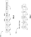
- FIG. 6 illustrates an example of an OFDM PPDU 600 having auto-detectable wireless LAN PHY version indication, in accordance with an example embodiment.
- the PPDU 600 includes an identifier field which is different than the RL-SIG, denoted Partial Repeated Legacy Signal (SIG) (PRL-SIG) field 608.
- SIG Partial Repeated Legacy Signal
- PRL-SIG Partial Repeated Legacy Signal
- the L-STF subfield 602 and L-LTF subfield 604 are the same as defined by IEEE 802.11a in the legacy OFDM PPDU 400 ( Figure 4A ).
- the PPDU 600 can include a SIG field particular to signaling information of the indicated wireless LAN PHY version, such as EHT-SIG in this example.
- the EHT-SIG and the payload data are collectively referred to as EHT-SIG and Data 610.
- RL-SIG is a fully repeated version of L-SIG 606 including Rate (which is set to "1101" to indicate a fixed code rate of 6 Mbps), Parity and Length which are used jointly for automatic detection IEEE 802.11ax. The Length is also used for calculation of the number of OFDM symbols in the data transmission in the PPDU.
- Figure 6 illustrates, instead of the RL-SIG field of IEEE 802.11ax, a different indicator denoted partial RL-SIG (PRL-SIG) field 608.
- PRL-SIG partial RL-SIG
- the Rate in the L-SIG is also set to "1101" to indicate a fixed code rate of 6 Mbps.
- IEEE 802.11ax a single Parity bit in the SIG may be used for error detection, but can cause an error detection problem in lower signal-to-noise (SNR) conditions.
- the Rate subfield is set to a known value in the L-SIG in IEEE 802.11ax, and is known by the receiver 320 to be 6 Mbps once the wireless LAN PHY version is known.
- At least Cyclic Redundancy Check (CRC) is used for the error detection.
- CRC Cyclic Redundancy Check
- the CRC is at the same corresponding subfield location (bit positions) as the Rate subfield defined in L-SIG 606.
- the bits in the remaining subfields defined in L-SIG 606 are repeated or partially repeated in the PRL-SIG field 608. In some examples, some bits of the remaining subfields defined in L-SIG 606 are different in the PRL-SIG field 608.
- automatic detection of the PPDU 600 of Figure 6 is conducted based on a CRC check, or in other examples, a combination of the CRC check plus a Parity check.
- the PRL-SIG field 608 of Figure 6 is modulated by the symbol modulator 312 using BPSK modulation. Automatic detection can further be conducted by recognition of the PRL-SIG field 608 as being modulated using BPSK modulation.
- FIG. 7 illustrates an example embodiment of the PRL-SIG field 700, introduced in Figure 6 as PRL-SIG field 608.
- the PRL-SIG field 700 is an identifier field for automatic detection of the wireless LAN PHY version.
- the subfields include the CRC subfield 702, Reserved (R) subfield 704, Length subfield 706, Parity (P) subfield 708, and Tail subfield 710.
- the 4 CRC bits and 6 Tail bits can be coded together using a code rate 1/2 BCC encoder, which is the same type of BCC encoder as used for L-SIG 606.
- the CRC in the CRC subfield 702 protects the Rate (i.e., bit positions b0-b3) and Length (i.e., b5-b16) in the L-SIG 606.
- Figure 8 illustrates an example method 800 of encoding the PRL-SIG field 700 of Figure 7 .
- the method 800 can be performed by the transmitter 310 ( Figure 3A ).
- the transmitter 310 performs segment parsing of the PRL-SIG field 700 to a first group of bits and a second group of bits.
- the first group of bits is the CRC subfield 702 and Tail subfield 710
- the second group of bits is the Reserved (R) subfield 704, Length subfield 706, and Parity (P) subfield 708.
- the transmitter 310 encodes the CRC and Tail using a code rate 1/2 BCC encoder.
- the transmitter 310 duplicates the coded Reserved, Length, and Parity bits generated in L-SIG.
- the transmitter 310 constructs together the coded bits from the first group of bits and the second group of bits and sends the constructed coded bits to the symbol modulator 312 ( Figure 3A ) for BPSK modulation.
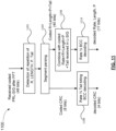
- Figure 9 illustrates an example method 900 of detection of the PRL-SIG field 700 from the signal generated by the method 800 of Figure 8 .
- a signal (PPDU) in time domain is received and the FFT block 324 of the receiver 320 performs Fast Fourier Transform to recover coded bits of the PRL-SIG field 700.
- the receiver 320 detects the repetition of Reserved (R) subfield 704, Length subfield 706, and Parity (P) subfield 708 from the PRL-SIG field 700, by comparing with the corresponding coded bits in L-SIG.
- the receiver 320 performs segment parsing of the received coded PRL-SIG to a first group of bits and a second group of bits.
- the first group of bits is the coded CRC subfield 702 and Tail subfield 710 and the second group of bits is the coded Reserved subfield 704, Length subfield 706, and Parity subfield 708.
- the receiver 320 performs code rate 1/2 BCC decoding on the first group of bits to generate the decoded bits of the CRC.
- the receiver 320 combines the second group of bits with coded L-SIG subfields Rate, Reserved, Length, Parity, and Tail, the combination of which at step 910 is decoded using code rate 1/2 BCC decoding to generate the decoded bits of Rate, Length and Parity.
- the receiver 320 can conduct a CRC check, using the decoded bits of CRC, onto the protected Rate and Length subfields (decoded from the L-SIG and the PRL-SIG). If the CRC check passes, the receiver determines the PPDU to be a specified wireless LAN PHY version, such as IEEE 802.11be. In other examples, the check is a combination of a CRC check, and a Parity check with the L-SIG.
- Figure 10 illustrates another example method 1000 of encoding the PRL-SIG field 700 of Figure 7 .
- the format of the PRL-SIG field 700 in this example is the same as shown in Figure 7 .
- the encoding for the CRC is different than in Figure 8 .
- the CRC bits are coded by coding block 334 with a code rate 1/2 tail biting BCC encoder.
- the tail biting BCC encoder does not use the tail bits of the Tail subfield 710 ( Figure 7 ).
- the CRC protects the Rate (i.e., bit positions b0-b3) and Length (i.e., b5-b16) of the L-SIG.
- the transmitter 310 performs segment parsing of the PRL-SIG field 700 to a first group of bits and a second group of bits.
- the first group of bits is the CRC subfield 702
- the second group of bits is the Reserved subfield 704, Length subfield 706, Parity subfield 708, and Tail subfield 710.
- the transmitter 310 encodes the CRC with the tail biting BCC encoder, which does not use the Tail bits.
- the transmitter 310 duplicates the coded Reserved, Length, Parity, and Tail generated in L-SIG.
- the transmitter 310 constructs together the coded bits from the first group of bits and the second group of bits and sends the constructed 48 coded bits to the symbol modulator 312 ( Figure 3A ) for BPSK modulation.
- Figure 11 illustrates an example method 1100 of detecting the coded PRL-SIG field 700 from the signal generated by the method 1000 of Figure 10 .
- the receiver 320 can perform detection of the CRC in the PRL-SIG field 700 and the Length and Parity in both the L-SIG and PRL-SIG.
- a signal (PPDU) in time domain is received and the FFT block 324 of the receiver 320 performs Fast Fourier Transform to recover coded bits of the PRL-SIG field 700.
- the receiver 320 detects the repetition of Reserved, Length, Parity and Tail in the coded bits of the PRL-SIG field 700.
- the receiver 320 performs segment parsing of the received coded PRL-SIG field 700 to a first group of bits and a second group of bits.
- the first group of bits is the coded CRC subfield 702 and a second group of bits is the coded Reserved, Length, Parity and Tail.
- the receiver 320 performs code rate 1/2 tail biting BCC decoding on the first group of bits to generate the decoded bits of the CRC.
- the receiver 320 combines the second group of bits with coded L-SIG subfields Rate, Reserved, Length, Parity, and Tail, the combination of which at step 1110 is decoded using code rate 1/2 BCC decoding to generate the decoded bits of Rate, Length and Parity.
- the receiver 320 can conduct a CRC check onto the protected Rate and Length subfields (from the L-SIG and/or the PRL-SIG). If the CRC check passes, the receiver 320 determines the PPDU to be a specified wireless LAN PHY version, such as IEEE 802.11be. In other examples, the check is a combination of the CRC check, and a Parity check with the L-SIG.
- Figure 12 illustrates a second example embodiment of the PRL-SIG field 1200, introduced in Figure 6 as PRL-SIG field 608, and includes the Cyclic Redundancy Check (CRC).
- the PRL-SIG field 1200 is an identifier field for automatic detection of the wireless LAN PHY version.
- the subfields in the PRL-SIG field 1200 include a 3-bit CRC subfield 1202 which protects the Length subfield, i.e., bit positions b5-b16 in L-SIG.
- the PRL-SIG field 1200 also includes a CRC Repeat subfield 1204.
- the CRC bits from CRC subfield 1202 repeat twice and the repeated CRC bits are located in bit positions b18-b23.
- the CRC protects the Rate subfield (i.e., b0-b3) and Length subfield (i.e., b5-b16) in L-SIG.
- the CRC bits in CRC Repeat subfield 1204 repeat once or repeat more than twice.
- Figure 13 illustrates an example method 1300 of encoding the PRL-SIG field 1200 of Figure 12 .
- the method 1300 can be performed by the transmitter 310 ( Figure 3A ).
- the transmitter 310 performs segment parsing of the PRL-SIG field 1200 to a first group of bits and a second group of bits.
- the first group is the CRC subfield 1202 and CRC Repeat subfield 1204, and the second group of bits is the Rate subfield (1 bit at b3), Reserved subfield, Length subfield, and Parity subfield.
- the transmitter 310 encodes the first group of bits containing the CRC using 2x repetition coding.
- the transmitter 310 duplicates the coded Rate (1 bit), Reserved, Length, and Parity generated in L-SIG bits.
- the transmitter 310 constructs together the coded bits from the first group of bits and the second group of bits and sends the constructed 48 coded bits to the symbol modulator 312 ( Figure 3A ) for BPSK modulation.
- Figure 14 illustrates an example method 1400 of receiving and detecting the coded PRL-SIG field 1200 from the signal generated by the method 1300 of Figure 13 .
- the receiver 320 can perform detection of the CRC in the PRL-SIG field 1200, and perform detection of the Length and Parity in both L-SIG and PRL-SIG.
- a signal (PPDU) in time domain is received and the FFT block 324 of the receiver 320 performs Fast Fourier Transform to recover coded bits of the PRL-SIG field 1200.
- the receiver 320 detects repetition of the Reserved, Length, and Parity in the coded bits of the PRL-SIG field 1200.
- the receiver 320 performs segment parsing of the received coded PRL-SIG field 1200 to a first group of bits and a second group of bits.
- the first group of bits is the repetition coded CRC (which were originally coded from the CRC subfield 1202 and CRC Repeat subfield 1204 of the PRL-SIG 1200).
- the second group of bits is the coded Rate (1 bit) subfield, Reserved subfield, Length subfield, Parity subfield, which were originally coded from the PRL-SIG 1200.
- the receiver 320 performs repetition decoding on the first group of bits to generate the decoded bits of the CRC.
- the receiver 320 combines the second group of bits with coded L-SIG subfields Rate, Reserved, Length, Parity, and Tail, the combination of which at step 1410 is decoded using code rate 1/2 BCC decoding to generate the decoded bits of Rate, Length and Parity.
- the receiver 320 can conduct a CRC check (or combination of CRC check and Parity check) onto the protected Rate and Length subfields (from PRL-SIG and L-SIG). If the CRC check (or combination of CRC check and Parity check) passes, the receiver determines the PPDU to be a specified wireless LAN PHY version, such as IEEE 802.11be. Otherwise, the receiver 320 can further detect whether the PPDU is an IEEE 802.11ax PPDU, or other PPDU types.
- FIG 15 illustrates another example embodiment of the PRL-SIG field 1500, introduced in Figure 6 as PRL-SIG field 608, in which the PRL-SIG field 1500 has a Flag subfield 1502.
- the PRL-SIG field 1500 is an identifier field for automatic detection of the wireless LAN PHY version.
- the PRL-SIG field 1500 includes a Reserved subfield 1504, a Length subfield 1506, a Parity subfield 1508, and a Tail subfield 1510.
- the Rate in the L-SIG is set to "1101" to indicate a fixed rate of 6 Mbps.
- An example embodiment of the PPDU 600 includes the partial RL-SIG (PRL-SIG) field 1500 which is subsequent to the L-SIG. Because the Rate subfield of the L-SIG is set to a known value in the L-SIG, the Rate does not need to be verified by the receiver 320. Therefore, in the PRL-SIG field 1500, the Rate subfield defined in L-SIG can be (at least partially) different than the PRL-SIG field 1500, with a Flag subfield 1502 at the same corresponding subfield location (corresponding bit positions). The remaining bits in the remaining subfields defined in L-SIG can be repeated in the PRL-SIG field 1500 in an example.
- PRL-SIG partial RL-SIG
- the Flag 1502 is set to a predefined value which is different from "1101" to indicate the specified wireless LAN PHY version of the PPDU, such as IEEE 802.11be or future amendments.
- Various different flags can each represent a different wireless LAN PHY version in some examples.
- the PRL-SIG field 1500 of Figure 15 includes a Flag subfield 1502 of 4 bits and Tail subfield 1510 of 6 bits.
- the Flag subfield 1502 and the Tail subfield 1510 are coded together by the coding block 334 using a code rate 1/2 BCC encoder (e.g., the same type of BCC encoder as used for L-SIG).
- the generation of the coded PRL-SIG 1500 from Figure 15 is similar to the method 800 of generating the coded PRL-SIG as illustrated in Figure 8 , by replacing "CRC" with "Flag".
- detection and interpreting Flag subfield 1502 in the PRL-SIG field 1500 and the Length and Parity in both L-SIG field and PRL-SIG field 1500 are similar to the method 900 of detecting and interpreting of the coded PRL-SIG as shown in Figure 9 , by replacing "CRC” with "Flag".
- the format of the PRL-SIG in this example is the same as the PRL-SIG 1500 as shown in Figure 15 .
- the encoding for the Flag is different than the PRL-SIG field 1500.
- the bits of the Flag subfield 1502 are coded with a code rate 1/2 tail biting BCC encoder.
- a tail biting convolutional code does not require tail bits for termination.
- Generation of the coded PRL-SIG is similar to the method 1000 for generation of the coded PRL-SIG 700 as illustrated in Figure 10 , by replacing "CRC" with "Flag".
- FIG 16 illustrates another example embodiment of the PRL-SIG field 1600, introduced in Figure 6 as PRL-SIG field 608.
- the PRL-SIG field 1600 is an identifier field for automatic detection of the wireless LAN PHY version.
- the PRL-SIG field 1600 includes a Flag subfield 1602, Repeated Rate subfield 1604, Reserved subfield 1606, Length subfield 1608, Parity subfield 1610, and Flag Repeat subfield 1612.
- the subfields in the PRL-SIG field 1600 include a 3-bit Flag subfield 1602, which is repeated twice and the repeated bits are located into the Flag Repeat subfield 1612 (bit positions b18-b23) of the PRL-SIG field 1600.
- the Flag subfield 1602 is repeated once, or more than twice, in the Flag Repeat subfield 1612.
- the method of generation of coded PRL-SIG 1600 from Figure 16 is similar to the method 1300 of generating the coded PRL-SIG 1200 as illustrated in Figure 13 , by replacing "CRC” with "Flag".
- the receiver 320 can check whether Rate, Length and Parity are valid by comparing to L-SIG as defined in IEEE 802.11ax. If Rate, Length and Parity are valid, the receiver 320 further checks Flag. If Flag is valid, the receiver 320 determines the PPDU is a specified wireless LAN PHY version such as IEEE 802.11be PPDU. Otherwise the PPDU is the HE PPDU. If Rate, Length or Parity is not valid, the receiver 320 can detect other legacy PPDU types.
- Figure 17E in an example embodiment, the auto-detection of the wireless LAN PHY version of the PPDU can be provided by an Identifier 1710.
- Figures 17A, 17B, 17C, 17D illustrate various example embodiments of an OFDM PPDU having the Identifier 1710, for indicating both the Physical Layer (PHY) version and the frame-type of the OFDM PPDU.
- PHY Physical Layer
- the Identifier 1710 can be a field or a subfield of the PPDU, and is contained within the PHY header (preamble).
- the Identifier 1710 has a PHY Version Identifier 1712.
- the PHY Version Identifier 1712 can be used to indicate the wireless LAN PHY version, e.g. IEEE 802.11 version or an amendment version. This allows for extensibility of the auto-detection method for IEEE 802.11be and future versions or standards.
- the Identifier 1710 also indicates the frame format type, referred to herein as a Frame Type Identifier 1714.
- the Frame Type Identifier 1714 can identify frame types such as MU, SU, TB or ER SU PPDU.
- the Frame Type Identifier 1714 can be used to identify any other possible frame type and future frame types.
- the Identifier 1710 is greater than 4 bits, greater than 10 bits, equal to 8 bits, or equal to 10 bits. In an example, 3 to 4 bits are used for the PHY Version Identifier 1712, and 6 to 7 bits are used for the Frame Type Identifier 1714 (totaling 10 bits in each case).
- Figures 17A, 17B, 17C, 17D show example locations of the Identifier 1710 in a PPDU.
- the number of symbols for the Identifier 1710 can be one symbol in an example, or more than one symbol in other examples.
- the Identifier 1710 can be subsequent to the RL-SIG or L-SIG.
- the Identifier 1710 can be within the SIG field particular to signaling information of the indicated wireless LAN PHY version, such as an EHT-SIG field as a subfield type.
- Figure 17A illustrates a first example embodiment of the OFDM PPDU 1700, wherein the Identifier 1710 is a field that is separate from, and subsequent to, the L-SIG and RL-SIG. In some examples, the Identifier 1710 is transmitted after the L-SIG and the RL-SIG.
- Figure 17B illustrates a second example embodiment of the OFDM PPDU 1702, wherein the Identifier 1710 is a field that is subsequent to L-SIG, and there is no RL-SIG in this example OFDM PPDU 1702. In some examples, the Identifier 1710 is transmitted after the L-SIG.
- Figure 17C illustrates a third example embodiment of the OFDM PPDU 1704, wherein the Identifier 1710 is a subfield within a SIG field particular to signaling information of the indicated wireless LAN PHY version, such as EHT-SIG 1716 in this example.
- the Identifier 1710 is a subfield within EHT-SIG 1716, and EHT-SIG 1716 is separate from, and subsequent to, L-SIG and RL-SIG.
- the Identifier 1710 subfield is transmitted after the L-SIG and the RL-SIG.
- the Identifier 1710 is a subfield within the EHT-SIG 1716, and EHT-SIG 1710 is subsequent to L-SIG. There is no RL-SIG in the example PPDU 1706 of Figure 17D . In some examples, the Identifier 1710 subfield is transmitted after the L-SIG.
- the Identifier 1710 includes the PHY Version 1712 as a separate subfield (separate bits) from the Frame Type Identifier 1714.
- the Identifier 1710 includes a first set of one or more bits that represent the PHY Version Identifier 1712 of the transmission and a second set of one or more bits that represent the Frame Type Identifier 1714 of the transmission.
- the Identifier 1710 includes at least some shared bits that represent both the wireless LAN PHY version of the transmission and the Frame Type Identifier 1714 of the transmission.
- a predefined coding scheme, lookup table, specified policy, algorithm, etc. can be used to translate the bits of the Identifier 1710 to each of the PHY Version Identifier 1712 and the Frame Type Identifier 1714.
- the Identifier 1710 can be within a trigger frame to solicit uplink transmission. In an example, not shown here, the Identifier 1710 can be within a preamble of the uplink transmission, having a field or subfield position similar to any one of the OFDM PPDU 1700, 1702, 1704, 1706.
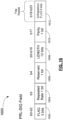
- Figure 18A illustrates an example embodiment of an OFDM PPDU 1800 having auto-detectable wireless LAN PHY version indication using a different version of the RL-SIG, by way of an Interleaved RL-SIG (IRL-SIG) field 1802.
- the IRL-SIG field 1802 is an identifier field for automatic detection the wireless LAN PHY version.
- the OFDM PPDU 1800 includes the same L-STF, L-LTF and L-SIG fields that are defined by legacy standards.
- the OFDM PPDU 1800 can include one or more SIG fields particular to signaling information of the indicated wireless LAN PHY version, such as EHT Signaling Fields 1804 in this example.
- a different version of the L-SIG in the coded bit level is the IRL-SIG field 1802, in which an interleaved version of the coded bits from the L-SIG is generated by re-arranging the order of bits from the L-SIG using a specified interleaver known by both the transmitter 310 and the receiver 320.
- the IRL-SIG field 1802 is subsequent to the L-SIG field in the OFDM PPDU 1800.
- the specified interleaver can be predetermined.
- the specified interleaver is particular to the wireless LAN PHY version (e.g. EHT 802.11be, or other version).
- the OFDM PPDU 1800 of Figure 18A automatic detection of the specified wireless LAN PHY version of the PPDU, e.g. IEEE 802.11be PPDU, is conducted based on a check by comparing L-SIG with the recovery of L-SIG from the IRL-SIG field 1802.
- the IRL-SIG field 1802 is represented in the data sub-carrier level.
- the data sub-carriers are obtained by interleaving the data sub-carriers of L-SIG.
- Figure 19 illustrates an example method 1900 of generating the IRL-SIG field 1802 of the OFDM PPDU 1800 of Figure 18A .
- the transmitter 310 interleaves coded bits in L-SIG field with the specified interleaver to generate the IRL-SIG field 1802.
- the coded bits of IRL-SIG field 1802 are BPSK modulated using the symbol modulator 312.
- the tone mapping block 314 of the transmitter 310 performs tone mapping of the BPSK modulated IRL-SIG.
- the IFFT block 315 of the transmitter 310 then applies OFDM modulation over the sub-carrier signals in accordance with the tone mapping, by performing an IFFT, arriving at an IRL-SIG symbol.
- step 1902 is performed after step 1904.
- the transmitter 301 first performs BPSK modulation on the IRL-SIG (which is the same as L-SIG at this point). Then, the transmitter 301 interleaves the BPSK modulated signals with a specified interleaver, prior to or as part of the tone mapping by the tone mapping block 314.
- Figure 20 illustrates an example method 2000 of receiving and detecting the IRL-SIG field 1802 from the signal generated by the method 1900 of Figure 19 .
- a signal (PPDU) in time domain is received and the FFT block 324 of the receiver 320 performs Fourier Transform to recover coded bits, and observes the first symbol after the L-SIG in the OFDM PPDU 1800 ( Figure 18 ).
- the receiver 320 performs deinterleaving of the recovered bits of the first symbol after the L-SIG.
- the receiver 320 checks the recovered bits and compares the deinterleaved Rate, Reserved, Length, Parity and Tail recovered at step 2004 with the L-SIG. If there is repetition detected in step 2006 between the recovered bits from step 2004 and the L-SIG, at step 2008 the receiver 320 detects and concludes that the PPDU is a specified wireless LAN PHY version, e.g., IEEE 802.11be in this example. If the check at step 2006 is not satisfied because the first symbol is found to be merely RL-SIG (non-interleaved), at step 2010 a check is performed between the Rate, Reserved, Length, Parity and Tail of RL-SIG (which is the first symbol after L-SIG) and L-SIG.
- RL-SIG non-interleaved
- the receiver detects the received PPDU as being an HE PPDU (802.11ax), or other checks are performed to determine whether the received PPDU is another wireless network type (which would be neither 802.11be nor 802.11ax).
- the alternate path 2014 in Figure 20 illustrates some instances where the HE PPDU (802.11ax) is checked separately from, or in parallel with, the deinterleaving step 2004.
- the first symbol after L-SIG may be RL-SIG.
- the receiver 320 checks the recovered bits by comparing the Rate, Reserved, Length, Parity and Tail of the RL-SIG with the L-SIG.
- the receiver detects the PPDU as being an HE PPDU (802.11ax).
- the receiver 320 checks the deinterleaved subcarriers of the first received symbol after L-SIG by comparing with the subcarriers of L-SIG. If there is repetition between the deinterleaved subcarriers of the first symbol after the L-SIG and the subcarriers of the L-SIG, the receiver detects and concludes that the PPDU is a specified wireless LAN PHY version, e.g., IEEE 802.11be in this example. If the check is not satisfied, a second repetition check is performed between the subcarriers of the first symbol after the L-SIG and the subcarriers of the L-SIG.
- a specified wireless LAN PHY version e.g., IEEE 802.11be
- the receiver detects and concludes that the received PPDU is an HE PPDU (802.11 ax). If the second repetition check is not satisfied between the subcarriers of the first symbol after the L-SIG and the subcarriers of the L-SIG, other checks are performed to determine whether the received PPDU is another wireless network type (which would be neither 802.11be nor 802.11ax).
- multiple different specified interleavers can each respectively indicate a different wireless network version (PHY type) to generate the IRL-SIG.
- the IRL-SIG is an indication of one of a plurality of possible PHY types.
- the receiver 320 can be configured to perform blind selection of different possible interleavers of the received transmission until the L-SIG is matched with the recovered L-SIG from the detected IRL-SIG field 1802. In examples, the blind selection can be performed in a specified order or in random order.
- Figure 18B illustrates an example embodiment of an OFDM PPDU 1820 having auto-detectable wireless LAN PHY version indication using a different version of the RL-SIG by way of a Scrambled RL-SIG (SRL-SIG) field 1822.
- the SRL-SIG field 1822 is an identifier field for automatic detection of the wireless LAN PHY version.
- the RL-SIG of a PPDU is modified by scrambling the L-SIG to generate a scrambled RL-SIG (SRL-SIG) field 1822.
- a scrambling sequence or scrambling function is used to generate the SRL-SIG field 1822.
- the SRL-SIG field 1822 in this OFDM PPDU 1820 instead of the IRL-SIG field 1802 of the OFDM PPDU 1800.
- the OFDM PPDU 1820 can include one or more SIG fields particular to signaling information of the indicated wireless LAN PHY version, such as EHT Signaling Fields in this example.
- the specified scrambling sequence can be predetermined.
- the specified scrambling sequence is particular to the wireless LAN PHY version (e.g. EHT, or other version).
- the generating and encoding of the OFDM PPDU 1820 of Figure 18B by the transmitter 310 can follow a similar method 1900 as in Figure 19 , with a scrambling step using the specified scrambling sequence (or scrambling function) performed instead of the interleaving step 1902.
- the receiving and interpreting of the OFDM PPDU 1820 for auto-detection of the wireless LAN PHY version by the receiver 320 can follow a similar method 2000 as in Figure 20 , with a descrambling step using the specified scrambling sequence (or descrambling function) performed instead of the deinterleaving step 2004.
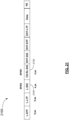
- Figure 21 illustrates an example of an OFDM PPDU 2100 having auto-detectable wireless LAN PHY version indication using a modified RL-SIG, denoted as Cyclic Shifted RL-SIG (CS-RL-SIG) field 2102, in accordance with an example embodiment.
- the CS-RL-SIG field 2102 is an identifier for automatic detection the wireless LAN PHY version.
- the OFDM PPDU 2100 keeps the L-STF, L-LTF and L-SIG symbols unchanged.
- the RL-SIG symbol is the symbol after the L-SIG symbol.
- a modification of the RL-SIG signal in the time domain is performed, in which the RL-SIG signal in the time domain after the IFFT block 315 is cyclic shifted before adding cyclic prefix (CP) by the CP generator 316.
- the cyclic shifting distance is known by both the transmitter 310 and the receiver 320.
- the CS-RL-SIG 2102 is a repeat of the L-SIG 2104.
- the receiver 320 can perform autodetection of the PPDU 2100 as being a specified wireless LAN PHY version, e.g., IEEE 802.11be, based a check of the repetition of a shifted version of CS-RL-SIG 2102 compared with L-SIG 2104.
- the CS-RL-SIG 2102 is a cyclic shifted repeat L-SIG signal 2104 in the time domain.
- the CS-RL-SIG signal is obtained by cyclic shifting, in the time domain, a RL-SIG signal before adding cyclic prefix by cyclic prefix generator 316.
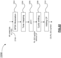
- Figure 22 illustrates an example method 2200 of generating and coding the CS-RL-SIG field 2102 shown in Figure 21 .
- the method 2200 can be performed by the transmitter 310.
- the coded bits of L-SIG 2104 are BPSK modulated using the symbol modulator 312.
- the tone mapping block 314 of the transmitter 310 tone maps the BPSK modulated L-SIG.
- the IFFT block 315 performs IFFT in accordance with the tone mapping, arriving at a RL-SIG symbol in time domain without cyclic prefix.
- the Cyclic Shifter 330 performs cyclic shifting at a specified cyclic shifting distance known by both the transmitter 310 and the receiver 320, to generate a CS-RL-SIG symbol.
- the cyclic prefix generator 316 adds a cyclic prefix to the CS-RL-SIG symbol.
- Detecting and decoding the coded CS-RL-SIG field is performed by the receiver 320 by, in time domain, removing the cyclic prefix by performing cyclic shifting to reverse the cyclic shifting from the method 2200 of Figure 22 .
- the recovered field from the coded CS-RL-SIG field 2102 is compared with the L-SIG 2104, with a match being the indication of the specified wireless LAN PHY version, e.g., IEEE 802.11be. Otherwise, another wireless network version or legacy version may be detected.
- multiple different specified cyclic shifting distances can each respectively indicate a different wireless network version (PHY type) to generate the CS-RL-SIG.
- Figure 23 illustrates an example method 2300 for enabling automatic wireless LAN PHY version detection within transmissions, in accordance with an example embodiment.
- the transmitter 310 generates a control signal for a transmission.
- the control signal includes i) a Legacy Signal (SIG) (L-SIG) symbol and ii) an identifier symbol which is generated from at least part of, but is not identical to, the L-SIG symbol, the identifier symbol indicates a wireless LAN PHY version of the transmission.
- SIG Legacy Signal
- L-SIG Legacy Signal
- control signal includes a Legacy Signal (SIG) (L-SIG) field, a Repeated L-SIG (RL-SIG) field, and an identifier separate from the L-SIG field and the RL-SIG field, the identifier indicates i) a wireless LAN PHY version of the transmission and ii) a frame type of the transmission.
- SIG Legacy Signal
- RL-SIG Repeated L-SIG
- the transmitter 310 transmits the control signal.
- the transmitting of the control signal includes transmitting the identifier symbol after the L-SIG symbol.
- the receiver 320 receives the control signal.
- the receiver 320 detects the wireless LAN PHY version of the transmission from the control signal.
- the receiver 320 interprets the control signal according to the detected wireless LAN PHY version.
- control signal for auto-detection of the wireless LAN PHY version
- the control signal can be within a trigger frame to solicit uplink transmission.
- control signal can be within a preamble of the uplink transmission.
- Figure 1C is a schematic diagram of an example wireless communication device 130, in accordance with example embodiments.
- the wireless communication device 130 may be the AP 101 or the STA 102, and may include the transmitter 310 ( Figure 3A ) or the receiver 320 ( Figure 3B ).
- the wireless communication device 130 may be used for both Single User (SU) and multiple access communications within the wireless communication system 100.
- Figure 1C shows a single instance of each component, there may be multiple instances of each component in the wireless communication device 130 and the wireless communication device 130 could be implemented using parallel and distributed architecture. Some of the components in Figure 1C are optional in some examples.
- the wireless communication device 130 may include one or more processing devices 132, such as a processor, a microprocessor, an application-specific integrated circuit (ASIC), a field-programmable gate array (FPGA), a dedicated logic circuitry, or combinations thereof.
- the wireless communication device 130 may also include one or more optional input/output (I/O) interface(s) 134, which may enable interfacing with one or more optional input devices 148 and output devices 150.
- processing devices 132 such as a processor, a microprocessor, an application-specific integrated circuit (ASIC), a field-programmable gate array (FPGA), a dedicated logic circuitry, or combinations thereof.
- ASIC application-specific integrated circuit
- FPGA field-programmable gate array
- the wireless communication device 130 may also include one or more optional input/output (I/O) interface(s) 134, which may enable interfacing with one or more optional input devices 148 and output devices 150.
- I/O input/output
- the wireless communication device 130 may include one or more network interfaces 136 for wired or wireless communication with a network (e.g., an intranet, the Internet, a Peer-to-Peer (P2P) network, a Wide Area Network (WAN), a wireless WAN (WWAN), a Local Area Network (LAN), or a Radio Access Network (RAN)) or other node.
- Wireless networks may make use of wireless connections transmitted over an antenna 152.
- the network interface(s) 136 may provide multiple access wireless communication via one or more transmitters or transmit antennas and one or more receivers or receive antennas, for example.
- one antenna 152 is shown, which may serve for multiple access transmission. However, in other examples there may be multiple antennas for transmitting and receiving.
- an antenna array may be used.
- the wireless communication device 130 may also include one or more storage units 138, which may include a mass storage unit such as a solid state drive, a hard disk drive, a magnetic disk drive or an optical disk drive.
- the wireless communication device 130 may include one or more non-transitory memories 140 that can include physical memory 142, which may include a volatile or non-volatile memory (e.g., a flash memory, a random access memory (RAM), or a read-only memory (ROM)).
- the memory 140 (as well as storage unit(s) 138) may store instructions for execution by the processing device(s) 132, such as to carry out processing such as those described in the present disclosure.
- the memory 140 may include other software instructions, such as for implementing an operating system (OS), and other applications/functions.
- OS operating system
- one or more data sets or modules may be provided by an external memory (e.g., an external drive in wired or wireless communication with the wireless communication device 130) or may be provided by a transitory or non-transitory computer-readable medium.
- Examples of non-transitory computer readable media include a RAM, a ROM, an erasable programmable ROM (EPROM), an electrically erasable programmable ROM (EEPROM), a flash memory, a CD-ROM, or other portable memory storage.
- a bus 144 providing communication among components of the wireless communication device 130.
- the bus 144 may be any suitable bus architecture including, for example, a memory bus, a peripheral bus or a video bus.
- Optional input device(s) 148 e.g., a keyboard, a mouse, a microphone, a touchscreen, or a keypad
- optional output device(s) 150 e.g., a display, a speaker or a printer
- one or more of the input device(s) 148 or the output device(s) 150 may be included as a component of the wireless communication device 130.
- the transmitter 310 and the receiver 320 may be included as one or more components of the wireless communication device 130.
- the transmitter 310 and the receiver 320 may be included as a single component for transmitting and receiving radio frequency (RF) analog signals.
- the transmitter 310 and the receiver 320 may be included as two separate components for transmitting and receiving radio frequency (RF) analog signals respectively.
- the transmitter 310 may provide transmission of PPDUs and the receiver 320 may receive the PPDU.
- the wireless communication device 130 also includes a power supply block 146 to supply power to the wireless communication device 130.
- the power supply block 146 can include a battery.
- the power supply block 146 includes a power adapter (e.g., AC/DC or DC/DC) for connection to an external power source and can be used for charging the battery.
- instructions that cause the processing device 132 to carry out methods in accordance with example embodiments are stored in storage unit(s) 138 or memory 140 of the wireless communication device 130.
- the processing device 132 may be one or more controllers, which may comprise a modulator or a processor.
- Example systems and methods described herein, in accordance with examples, can be implemented by the one or more controllers.
- the one or more controllers can comprise hardware, software, or a combination of hardware and software, depending on the particular component and function.
- the one or more controllers can include analog or digital components, and can include one or more processors, one or more non-transitory storage mediums such as memory storing instructions executable by the one or more processors, one or more transceivers (or separate transmitters and receivers), one or more signal processors (analog or digital), and one or more analog circuit components.
- Example embodiments can applied to MU communication, single user (SU) communication, trigger based (TB) communication, or extended range (ER) TB communication.
- SU single user
- TB trigger based
- ER extended range
- An example embodiment is a non-transitory computer-readable medium which stores instructions that when executed by a processing device causes the processing device to perform any of the described methods, processes or functions.
- the example embodiments described above may be implemented by using hardware only or by using software and a necessary universal hardware platform. Based on such understandings, the technical solution of some example embodiments may be embodied in the form of a software product.
- the software product may be stored in a non-volatile or non-transitory storage medium, which can be a compact disk read-only memory (CD-ROM), Universal Serial Bus (USB) flash disk, or a removable hard disk.
- the software product includes a number of instructions that enable a computer device (personal computer, server, or network device) to execute the methods provided in the example embodiments.
- the software product may additionally include a number of instructions that enable a computer device to execute operations for configuring or programming a digital logic apparatus in accordance with example embodiments.
- Example apparatuses and methods described herein, in accordance with example embodiments, can be implemented by one or more controllers.
- the controllers can comprise hardware, software, or a combination of hardware and software, depending on the particular application, component or function.
- the one or more controllers can include analog or digital components, and can include one or more processors, one or more non-transitory storage mediums such as memory storing instructions executable by the one or more processors, one or more transceivers (or separate transmitters and receivers), one or more signal processors (analog and/or digital), and/or one or more analog circuit components.
- the boxes may represent events, steps, functions, processes, modules, messages, and/or state-based operations, etc.
- some of the steps or processes may be performed in a different order provided that the result of the changed order of any given step will not prevent or impair the occurrence of subsequent steps.
- some of the messages or steps described above may be removed or combined in other embodiments, and some of the messages or steps described above may be separated into a number of sub-messages or sub-steps in other embodiments. Even further, some or all of the steps may be repeated, as necessary.
- Elements described as methods or steps similarly apply to systems or subcomponents, and vice-versa. Reference to such words as "sending” or “receiving” could be interchanged depending on the perspective of the particular device.
Landscapes
- Engineering & Computer Science (AREA)
- Computer Networks & Wireless Communication (AREA)
- Signal Processing (AREA)
- Computer Security & Cryptography (AREA)
- Mobile Radio Communication Systems (AREA)
Claims (18)
- Verfahren zum Ermöglichen von "Wireless Local Area Network"-, WLAN-, - "Physical Layer"-, -PHY-, Versionserkennung, durchgeführt von einer Drahtloskommunikationsvorrichtung (101), wobei das Verfahren umfasst:
Erzeugen (2302) eines Steuersignals (1710) für eine Uplink-Übertragung, wobei das Steuersignal beinhaltet:
eine erste Kennung (1712), die eine WLAN-PHY-Version der Übertragung angibt; und Übertragen (2304) des Steuersignals (1710) in einem Trigger-Frame, wobei die erste Kennung (1712) ein Kennungsfeld oder ein Kennungsunterfeld des Trigger-Frames ist. - Verfahren nach Anspruch 1, wobei sich das Steuersignal (1710) in einem Feld befindet, das von einem Signal-, SIG-, Feld (1804) getrennt ist, das für Signalisierungsinformationen der angegebenen WLAN-PHY-Version spezifisch ist.
- Verfahren nach einem der Ansprüche 1 bis 2, wobei das Steuersignal (1710) eine zweite Kennung (1714) beinhaltet, die die Frame-Art der Übertragung angibt.
- Verfahren nach einem der Ansprüche 1 bis 3, wobei die WLAN-PHY-Version (1712) eine "Institute of Electrical and Electronics Engineers", IEEE, 802.11-Version oder eine ergänzte Version der IEEE 802.11-Version ist.
- Drahtloskommunikationsvorrichtung (130), umfassend:eine Antenne (152);eine Verarbeitungsvorrichtung (132);einen Speicher (142), der der Verarbeitungsvorrichtung zugeordnet ist, zum Speichern von Anweisungen, die bei ihrer Ausführung durch die Verarbeitungsvorrichtung die Drahtloskommunikationsvorrichtung zu folgenden Vorgängen veranlassen:
Erzeugen (2302) eines Steuersignals (1710) für eine Uplink-Übertragung, wobei das Steuersignal beinhaltet:eine erste Kennung (1712), die eine "Wireless Local Area Network"-, WLAN-, - "Physical Layer"-, -PHY-, Version der Übertragung angibt; undÜbertragen (2304) des Steuersignals in einem Trigger-Frame, wobei die erste Kennung ein Kennungsfeld oder ein Kennungsunterfeld des Trigger-Frames ist. - Drahtloskommunikationsvorrichtung nach Anspruch 5, wobei sich das Steuersignal (1710) in einem Feld befindet, das von einem Signal-, SIG-, Feld (1804) getrennt ist, das für Signalisierungsinformationen der angegebenen WLAN-PHY-Version spezifisch ist.
- Drahtloskommunikationsvorrichtung nach einem der Ansprüche 5 bis 6, wobei das Steuersignal (1710) eine zweite Kennung (1714) beinhaltet, die die Frame-Art der Übertragung angibt.
- Drahtloskommunikationsvorrichtung nach einem der Ansprüche 5 bis 7, wobei die WLAN-PHY-Version (1712) eine "Institute of Electrical and Electronics Engineers", IEEE, 802.11-Version oder eine ergänzte Version der IEEE 802.11-Version ist.
- Computerlesbares Medium (142), das Anweisungen zur Ausführung durch eine Verarbeitungsvorrichtung (132) einer Drahtloskommunikationsvorrichtung (130) zum Durchführen des Verfahrens nach einem oder mehreren der Ansprüche 1 bis 4 speichert.
- Verfahren zum Ermöglichen von "Wireless Local Area Network"-, WLAN-, - "Physical Layer"-, -PHY-, Versionserkennung, durchgeführt von einer Drahtloskommunikationsvorrichtung (320), wobei das Verfahren umfasst:Empfangen (2306) eines Trigger-Frames, der ein Steuersignal (1710) für eine Uplink-Übertragung enthält, wobei das Steuersignal eine erste Kennung (1712) beinhaltet, die eine WLAN-PHY-Version (2308) der Übertragung angibt, wobei die erste Kennung ein Kennungsfeld oder ein Kennungsunterfeld des Trigger-Frames ist;Senden der Uplink-Übertragung als Reaktion auf den Trigger-Frame, wobei die Uplink-Übertragung einen Frame umfasst, der in Übereinstimmung (2310) mit der WLAN-PHY-Version formatiert ist, die durch die erste Kennung (1712) angegeben wird.
- Verfahren nach Anspruch 10, wobei die Drahtloskommunikationsvorrichtung das Steuersignal (1710) aus einem Feld liest, das von einem Signal-, SIG-, Feld getrennt ist, das für Signalisierungsinformationen der angegebenen WLAN-PHY-Version spezifisch ist.
- Verfahren nach einem der Ansprüche 10 bis 11, wobei die Drahtloskommunikationsvorrichtung die Frame-Art der Übertragung aus einer zweiten Kennung (1714) bestimmt, die im Steuersignal (1710) enthalten ist.
- Verfahren nach einem der Ansprüche 10 bis 12, wobei die WLAN-PHY-Version eine "Institute of Electrical and Electronics Engineers", IEEE, 802.11-Version oder eine ergänzte Version der IEEE 802.11-Version ist.
- Drahtloskommunikationsvorrichtung, umfassend:eine Antenne (152);eine Verarbeitungsvorrichtung (132);einen Speicher (142), der der Verarbeitungsvorrichtung zugeordnet ist, zum Speichern von Anweisungen, die bei ihrer Ausführung durch die Verarbeitungsvorrichtung die Drahtloskommunikationsvorrichtung zu folgenden Vorgängen veranlassen:Empfangen (2306) eines Trigger-Frames, der ein Steuersignal (1710) für eine Uplink-Übertragung enthält, wobei das Steuersignal eine erste Kennung (1712) beinhaltet, die eine "Wireless Local Area Network"-, WLAN-, -"Physical Layer"-, -PHY-, Version der Übertragung angibt, wobei die erste Kennung ein Kennungsfeld oder ein Kennungsunterfeld des Trigger-Frames ist;Senden der Uplink-Übertragung als Reaktion auf den Trigger-Frame, wobei die Uplink-Übertragung einen Frame umfasst, der in Übereinstimmung (2310) mit der WLAN-PHY-Version (1712) formatiert ist, die durch die erste Kennung angegeben wird.
- Drahtloskommunikationsvorrichtung nach Anspruch 14, wobei die Anweisungen die Drahtloskommunikationsvorrichtung veranlassen, das Steuersignal (1710) aus einem Feld zu lesen, das von einem Signal-, SIG-, Feld (1804) getrennt ist, das für Signalisierungsinformationen der angegebenen WLAN-PHY-Version spezifisch ist.
- Drahtloskommunikationsvorrichtung nach einem der Ansprüche 14 bis 15, wobei die Anweisungen die Drahtloskommunikationsvorrichtung veranlassen, die Frame-Art der Übertragung aus einer zweiten Kennung (1714) zu bestimmen, die im Steuersignal (1710) enthalten ist.
- Drahtloskommunikationsvorrichtung nach einem der Ansprüche 14 bis 16, wobei die WLAN-PHY-Version (1712) eine "Institute of Electrical and Electronics Engineers", IEEE, 802.11-Version oder eine ergänzte Version der IEEE 802.11-Version ist.
- Computerlesbares Medium (142), das Anweisungen zur Ausführung durch eine Verarbeitungsvorrichtung (132) einer Drahtloskommunikationsvorrichtung zum Durchführen des Verfahrens nach einem oder mehreren der Ansprüche 10 bis 13 speichert.
Priority Applications (1)
| Application Number | Priority Date | Filing Date | Title |
|---|---|---|---|
| EP25154901.0A EP4539538A1 (de) | 2019-08-07 | 2020-08-07 | Präambel mit detektierbarer wlan versionsidentifikation |
Applications Claiming Priority (3)
| Application Number | Priority Date | Filing Date | Title |
|---|---|---|---|
| US201962884136P | 2019-08-07 | 2019-08-07 | |
| US16/944,993 US11387937B2 (en) | 2019-08-07 | 2020-07-31 | Preamble with detectable WLAN version identification |
| PCT/CN2020/107611 WO2021023287A1 (en) | 2019-08-07 | 2020-08-07 | Preamble with detectable wlan version identification |
Related Child Applications (2)
| Application Number | Title | Priority Date | Filing Date |
|---|---|---|---|
| EP25154901.0A Division-Into EP4539538A1 (de) | 2019-08-07 | 2020-08-07 | Präambel mit detektierbarer wlan versionsidentifikation |
| EP25154901.0A Division EP4539538A1 (de) | 2019-08-07 | 2020-08-07 | Präambel mit detektierbarer wlan versionsidentifikation |
Publications (4)
| Publication Number | Publication Date |
|---|---|
| EP4005268A1 EP4005268A1 (de) | 2022-06-01 |
| EP4005268A4 EP4005268A4 (de) | 2022-08-17 |
| EP4005268B1 true EP4005268B1 (de) | 2025-03-05 |
| EP4005268C0 EP4005268C0 (de) | 2025-03-05 |
Family
ID=74498131
Family Applications (2)
| Application Number | Title | Priority Date | Filing Date |
|---|---|---|---|
| EP25154901.0A Pending EP4539538A1 (de) | 2019-08-07 | 2020-08-07 | Präambel mit detektierbarer wlan versionsidentifikation |
| EP20851164.2A Active EP4005268B1 (de) | 2019-08-07 | 2020-08-07 | Präambel mit detektierbarer wlan-versionserkennung |
Family Applications Before (1)
| Application Number | Title | Priority Date | Filing Date |
|---|---|---|---|
| EP25154901.0A Pending EP4539538A1 (de) | 2019-08-07 | 2020-08-07 | Präambel mit detektierbarer wlan versionsidentifikation |
Country Status (7)
| Country | Link |
|---|---|
| US (4) | US11387937B2 (de) |
| EP (2) | EP4539538A1 (de) |
| JP (1) | JP7367178B2 (de) |
| KR (2) | KR20240126078A (de) |
| CN (4) | CN114586408B (de) |
| ES (1) | ES3020384T3 (de) |
| WO (1) | WO2021023287A1 (de) |
Families Citing this family (5)
| Publication number | Priority date | Publication date | Assignee | Title |
|---|---|---|---|---|
| US11582007B2 (en) * | 2020-05-06 | 2023-02-14 | Mediatek Inc. | Apparatuses and methods for resource unit (RU) allocation signaling to support trigger-based physical layer protocol data unit (TB PPDU) with multi-RU |
| KR20230129411A (ko) * | 2021-01-11 | 2023-09-08 | 퀄컴 인코포레이티드 | 라디오 액세스 기술에 대한 표준 변종에 기반한 네트워크선택 |
| US12225451B2 (en) | 2021-04-02 | 2025-02-11 | Samsung Electronics Co., Ltd. | Apparatus and method for extended signal field |
| US20240097820A1 (en) * | 2022-09-19 | 2024-03-21 | Mediatek Inc. | Performance Enhancement Of RU Duplication With Predefined Interleaving Patterns In Wireless Communications |
| US20250330357A1 (en) * | 2024-04-22 | 2025-10-23 | Maxlinear, Inc. | Mixed generation preamble transmission |
Citations (2)
| Publication number | Priority date | Publication date | Assignee | Title |
|---|---|---|---|---|
| US20060199558A1 (en) * | 2005-02-12 | 2006-09-07 | Alain Chiodini | Apparatus and method for detecting preambles according to IEEE 802.11A/B/G wireless LAN standards and its application to a 802.11 multimode receiver |
| US20160277978A1 (en) * | 2013-11-11 | 2016-09-22 | Telefonaktiebolaget Lm Ericsson (Publ) | Controlling the Operation of Mobile Terminals with Respect to Multiple Radio Access Technologies |
Family Cites Families (34)
| Publication number | Priority date | Publication date | Assignee | Title |
|---|---|---|---|---|
| JP5649011B2 (ja) | 2009-04-13 | 2015-01-07 | マーベル ワールド トレード リミテッド | Wlan用の物理層フレーム形式 |
| KR101690791B1 (ko) * | 2009-08-18 | 2017-01-09 | 한국전자통신연구원 | 초광대역 무선통신 시스템에서 프로토콜 버전을 포함하는 프레임을 송수신하는 장치 및 방법 |
| US8755363B2 (en) | 2009-09-15 | 2014-06-17 | Qualcomm Incorporated | Physical layer signaling of control parameters |
| US8238316B2 (en) * | 2009-12-22 | 2012-08-07 | Intel Corporation | 802.11 very high throughput preamble signaling field with legacy compatibility |
| US9357437B2 (en) | 2011-04-28 | 2016-05-31 | Intel Corporation | Methods and arrangements for communications in low power wireless networks |
| WO2013077652A1 (ko) * | 2011-11-24 | 2013-05-30 | 엘지전자 주식회사 | 무선랜 시스템에서 채널 사운딩 수행 방법 및 이를 지원하는 장치 |
| KR20130059686A (ko) * | 2011-11-29 | 2013-06-07 | 한국전자통신연구원 | 무선 통신 시스템에서 무선 신호 송수신 방법 및 이를 지원하는 장치 |
| US9363707B2 (en) * | 2011-12-29 | 2016-06-07 | Qualcomm Incorporated | Systems and methods for generating and decoding short control frames in wireless communications |
| US8811507B2 (en) * | 2012-04-09 | 2014-08-19 | Qualcomm Incorporated | Systems and methods for wireless communication in sub gigahertz bands |
| US9716606B2 (en) * | 2014-04-28 | 2017-07-25 | Newracom, Inc. | Method for transmitting frame and method for detecting transmission mode |
| CN106716944B (zh) | 2014-08-04 | 2020-09-08 | 英特尔Ip公司 | 用于hew中的字段的无线设备、方法和计算机可读介质 |
| US10044421B2 (en) * | 2014-08-26 | 2018-08-07 | Intel IP Corporation | Wireless communication via combined channel training and physical layer header signaling |
| WO2016032258A2 (ko) * | 2014-08-27 | 2016-03-03 | 엘지전자(주) | 무선 통신 시스템에서 데이터 전송 방법 및 이를 위한 장치 |
| WO2016049928A1 (zh) | 2014-09-30 | 2016-04-07 | 华为技术有限公司 | 用于无线局域网的数据传输的方法和装置 |
| JP6457634B2 (ja) * | 2014-09-30 | 2019-01-23 | 華為技術有限公司Huawei Technologies Co.,Ltd. | データ伝送方法および装置 |
| KR20160055718A (ko) * | 2014-11-10 | 2016-05-18 | 뉴라컴 인코포레이티드 | 무선랜에서 프레임 송수신 방법 및 장치 |
| WO2016104886A1 (ko) * | 2014-12-25 | 2016-06-30 | 엘지전자 주식회사 | 트리거 프레임을 기반으로 한 데이터 단위의 전송 방법 및 장치 |
| US9806927B2 (en) * | 2015-01-21 | 2017-10-31 | Intel IP Corporation | Method, apparatus, and computer readable medium for signaling high efficiency packet formats using a legacy portion of the preamble in wireless local-area networks |
| WO2016167609A1 (ko) * | 2015-04-16 | 2016-10-20 | 엘지전자(주) | 무선 통신 시스템에서 채널 사운딩 방법 및 이를 위한 장치 |
| KR102063217B1 (ko) * | 2015-04-16 | 2020-01-07 | 엘지전자 주식회사 | 무선 통신 시스템에서 채널 사운딩 방법 및 이를 위한 장치 |
| US9641234B2 (en) * | 2015-04-24 | 2017-05-02 | Newracom, Inc. | Preamble and payload for high efficiency (HE) transmission |
| US10122563B1 (en) * | 2015-06-18 | 2018-11-06 | Marvell International Ltd. | Orthogonal frequency division multiplex data unit generation and decoding |
| WO2017004836A1 (zh) * | 2015-07-09 | 2017-01-12 | 华为技术有限公司 | 一种数据检测方法和装置 |
| JP2017022586A (ja) * | 2015-07-11 | 2017-01-26 | 国立大学法人九州工業大学 | 無線通信装置及び方法 |
| JP2017059911A (ja) * | 2015-09-14 | 2017-03-23 | 株式会社東芝 | 無線通信装置および無線通信方法 |
| WO2017069534A1 (ko) | 2015-10-20 | 2017-04-27 | 엘지전자 주식회사 | 무선랜 시스템에서 트리거 프레임을 전송하는 방법 및 이를 이용한 단말 |
| US20170111196A1 (en) * | 2015-10-20 | 2017-04-20 | Mediatek Inc. | Method of embedding auxiliary information into legacy physical layer preamble |
| US10470128B2 (en) * | 2015-11-18 | 2019-11-05 | Newracom, Inc. | Early detection procedure of high-efficiency frame and decision timing for spatial reuse |
| US10135563B2 (en) | 2016-09-28 | 2018-11-20 | Intel IP Corporation | Triggering of an uplink pair of packets in a wireless local area network |
| US10904920B1 (en) | 2017-01-07 | 2021-01-26 | Newracom, Inc. | Trigger-based random access for wireless device |
| WO2019190150A1 (ko) * | 2018-03-26 | 2019-10-03 | 엘지전자 주식회사 | 무선랜 시스템에서 s-tdma를 기반으로 ppdu를 전송하는 방법 및 장치 |
| US10716119B2 (en) * | 2018-07-09 | 2020-07-14 | Huawei Technologies Canada Co., Ltd. | Scheduling of successive multi-user (MU) transmissions in a wireless local area network (LAN) |
| US11515982B2 (en) | 2020-11-12 | 2022-11-29 | Qualcomm Incorporated | Special user information field for trigger frame |
| US11646854B2 (en) | 2021-04-30 | 2023-05-09 | Qualcomm Incorporated | Distributed resource unit signaling |
-
2020
- 2020-07-31 US US16/944,993 patent/US11387937B2/en active Active
- 2020-08-07 CN CN202080054494.5A patent/CN114586408B/zh active Active
- 2020-08-07 ES ES20851164T patent/ES3020384T3/es active Active
- 2020-08-07 WO PCT/CN2020/107611 patent/WO2021023287A1/en not_active Ceased
- 2020-08-07 KR KR1020247027249A patent/KR20240126078A/ko active Pending
- 2020-08-07 JP JP2022507452A patent/JP7367178B2/ja active Active
- 2020-08-07 EP EP25154901.0A patent/EP4539538A1/de active Pending
- 2020-08-07 EP EP20851164.2A patent/EP4005268B1/de active Active
- 2020-08-07 CN CN202411457002.3A patent/CN119629670A/zh active Pending
- 2020-08-07 KR KR1020227007336A patent/KR102829752B1/ko active Active
- 2020-08-07 CN CN202411457846.8A patent/CN119545425A/zh active Pending
- 2020-08-07 CN CN202310873299.0A patent/CN116963177B/zh active Active
-
2022
- 2022-07-11 US US17/862,279 patent/US11949506B2/en active Active
-
2023
- 2023-07-06 US US18/218,829 patent/US12068850B2/en active Active
-
2024
- 2024-07-11 US US18/769,558 patent/US20240364453A1/en active Pending
Patent Citations (2)
| Publication number | Priority date | Publication date | Assignee | Title |
|---|---|---|---|---|
| US20060199558A1 (en) * | 2005-02-12 | 2006-09-07 | Alain Chiodini | Apparatus and method for detecting preambles according to IEEE 802.11A/B/G wireless LAN standards and its application to a 802.11 multimode receiver |
| US20160277978A1 (en) * | 2013-11-11 | 2016-09-22 | Telefonaktiebolaget Lm Ericsson (Publ) | Controlling the Operation of Mobile Terminals with Respect to Multiple Radio Access Technologies |
Also Published As
| Publication number | Publication date |
|---|---|
| KR20220045188A (ko) | 2022-04-12 |
| CN116963177B (zh) | 2024-07-05 |
| KR20240126078A (ko) | 2024-08-20 |
| ES3020384T3 (en) | 2025-05-22 |
| US20240364453A1 (en) | 2024-10-31 |
| JP7367178B2 (ja) | 2023-10-23 |
| KR102829752B1 (ko) | 2025-07-03 |
| EP4539538A1 (de) | 2025-04-16 |
| EP4005268C0 (de) | 2025-03-05 |
| WO2021023287A1 (en) | 2021-02-11 |
| US20240007223A1 (en) | 2024-01-04 |
| US20230006768A1 (en) | 2023-01-05 |
| CN116963177A (zh) | 2023-10-27 |
| US20210044381A1 (en) | 2021-02-11 |
| CN119629670A (zh) | 2025-03-14 |
| EP4005268A1 (de) | 2022-06-01 |
| US12068850B2 (en) | 2024-08-20 |
| EP4005268A4 (de) | 2022-08-17 |
| CN114586408A (zh) | 2022-06-03 |
| CN114586408B (zh) | 2024-10-29 |
| CN119545425A (zh) | 2025-02-28 |
| JP2022543631A (ja) | 2022-10-13 |
| US11949506B2 (en) | 2024-04-02 |
| US11387937B2 (en) | 2022-07-12 |
Similar Documents
| Publication | Publication Date | Title |
|---|---|---|
| US12237920B2 (en) | Physical layer frame format for WLAN | |
| EP4005268B1 (de) | Präambel mit detektierbarer wlan-versionserkennung | |
| US8942320B2 (en) | Data unit format for multi-user data in long-range wireless local area networks (WLANs) | |
| AU2011245845B2 (en) | Method and apparatus for transmitting data in very high throughput wireless local area network system | |
| EP3425841A1 (de) | Modulation eines signalfeldes bei einem frame-header in einem wlan | |
| KR20180026768A (ko) | 시그널링 필드를 이용하는 무선 통신 방법 및 무선 통신단말 | |
| CN118741700A (zh) | 用于无线局域网系统中的基于多资源单元的通信的设备和方法 |
Legal Events
| Date | Code | Title | Description |
|---|---|---|---|
| STAA | Information on the status of an ep patent application or granted ep patent |
Free format text: STATUS: THE INTERNATIONAL PUBLICATION HAS BEEN MADE |
|
| PUAI | Public reference made under article 153(3) epc to a published international application that has entered the european phase |
Free format text: ORIGINAL CODE: 0009012 |
|
| STAA | Information on the status of an ep patent application or granted ep patent |
Free format text: STATUS: REQUEST FOR EXAMINATION WAS MADE |
|
| 17P | Request for examination filed |
Effective date: 20220223 |
|
| AK | Designated contracting states |
Kind code of ref document: A1 Designated state(s): AL AT BE BG CH CY CZ DE DK EE ES FI FR GB GR HR HU IE IS IT LI LT LU LV MC MK MT NL NO PL PT RO RS SE SI SK SM TR |
|
| A4 | Supplementary search report drawn up and despatched |
Effective date: 20220714 |
|
| RIC1 | Information provided on ipc code assigned before grant |
Ipc: H04W 84/12 20090101ALI20220708BHEP Ipc: H04W 28/06 20090101AFI20220708BHEP |
|
| DAV | Request for validation of the european patent (deleted) | ||
| DAX | Request for extension of the european patent (deleted) | ||
| STAA | Information on the status of an ep patent application or granted ep patent |
Free format text: STATUS: EXAMINATION IS IN PROGRESS |
|
| 17Q | First examination report despatched |
Effective date: 20230526 |
|
| GRAP | Despatch of communication of intention to grant a patent |
Free format text: ORIGINAL CODE: EPIDOSNIGR1 |
|
| STAA | Information on the status of an ep patent application or granted ep patent |
Free format text: STATUS: GRANT OF PATENT IS INTENDED |
|
| INTG | Intention to grant announced |
Effective date: 20241022 |
|
| GRAS | Grant fee paid |
Free format text: ORIGINAL CODE: EPIDOSNIGR3 |
|
| GRAA | (expected) grant |
Free format text: ORIGINAL CODE: 0009210 |
|
| STAA | Information on the status of an ep patent application or granted ep patent |
Free format text: STATUS: THE PATENT HAS BEEN GRANTED |
|
| AK | Designated contracting states |
Kind code of ref document: B1 Designated state(s): AL AT BE BG CH CY CZ DE DK EE ES FI FR GB GR HR HU IE IS IT LI LT LU LV MC MK MT NL NO PL PT RO RS SE SI SK SM TR |
|
| REG | Reference to a national code |
Ref country code: GB Ref legal event code: FG4D |
|
| REG | Reference to a national code |
Ref country code: CH Ref legal event code: EP |
|
| REG | Reference to a national code |
Ref country code: DE Ref legal event code: R096 Ref document number: 602020047371 Country of ref document: DE |
|
| REG | Reference to a national code |
Ref country code: IE Ref legal event code: FG4D |
|
| U01 | Request for unitary effect filed |
Effective date: 20250307 |
|
| U07 | Unitary effect registered |
Designated state(s): AT BE BG DE DK EE FI FR IT LT LU LV MT NL PT RO SE SI Effective date: 20250314 |
|
| REG | Reference to a national code |
Ref country code: ES Ref legal event code: FG2A Ref document number: 3020384 Country of ref document: ES Kind code of ref document: T3 Effective date: 20250522 |
|
| PG25 | Lapsed in a contracting state [announced via postgrant information from national office to epo] |
Ref country code: RS Free format text: LAPSE BECAUSE OF FAILURE TO SUBMIT A TRANSLATION OF THE DESCRIPTION OR TO PAY THE FEE WITHIN THE PRESCRIBED TIME-LIMIT Effective date: 20250605 |
|
| PG25 | Lapsed in a contracting state [announced via postgrant information from national office to epo] |
Ref country code: NO Free format text: LAPSE BECAUSE OF FAILURE TO SUBMIT A TRANSLATION OF THE DESCRIPTION OR TO PAY THE FEE WITHIN THE PRESCRIBED TIME-LIMIT Effective date: 20250605 |
|
| PG25 | Lapsed in a contracting state [announced via postgrant information from national office to epo] |
Ref country code: HR Free format text: LAPSE BECAUSE OF FAILURE TO SUBMIT A TRANSLATION OF THE DESCRIPTION OR TO PAY THE FEE WITHIN THE PRESCRIBED TIME-LIMIT Effective date: 20250305 |
|
| PG25 | Lapsed in a contracting state [announced via postgrant information from national office to epo] |
Ref country code: GR Free format text: LAPSE BECAUSE OF FAILURE TO SUBMIT A TRANSLATION OF THE DESCRIPTION OR TO PAY THE FEE WITHIN THE PRESCRIBED TIME-LIMIT Effective date: 20250606 |
|
| PG25 | Lapsed in a contracting state [announced via postgrant information from national office to epo] |
Ref country code: SM Free format text: LAPSE BECAUSE OF FAILURE TO SUBMIT A TRANSLATION OF THE DESCRIPTION OR TO PAY THE FEE WITHIN THE PRESCRIBED TIME-LIMIT Effective date: 20250305 |
|
| U20 | Renewal fee for the european patent with unitary effect paid |
Year of fee payment: 6 Effective date: 20250901 |
|
| PGFP | Annual fee paid to national office [announced via postgrant information from national office to epo] |
Ref country code: ES Payment date: 20250905 Year of fee payment: 6 |
|
| PG25 | Lapsed in a contracting state [announced via postgrant information from national office to epo] |
Ref country code: PL Free format text: LAPSE BECAUSE OF FAILURE TO SUBMIT A TRANSLATION OF THE DESCRIPTION OR TO PAY THE FEE WITHIN THE PRESCRIBED TIME-LIMIT Effective date: 20250305 |
|
| PGFP | Annual fee paid to national office [announced via postgrant information from national office to epo] |
Ref country code: GB Payment date: 20250703 Year of fee payment: 6 |
|
| PG25 | Lapsed in a contracting state [announced via postgrant information from national office to epo] |
Ref country code: CZ Free format text: LAPSE BECAUSE OF FAILURE TO SUBMIT A TRANSLATION OF THE DESCRIPTION OR TO PAY THE FEE WITHIN THE PRESCRIBED TIME-LIMIT Effective date: 20250305 |
|
| PG25 | Lapsed in a contracting state [announced via postgrant information from national office to epo] |
Ref country code: SK Free format text: LAPSE BECAUSE OF FAILURE TO SUBMIT A TRANSLATION OF THE DESCRIPTION OR TO PAY THE FEE WITHIN THE PRESCRIBED TIME-LIMIT Effective date: 20250305 |
|
| PG25 | Lapsed in a contracting state [announced via postgrant information from national office to epo] |
Ref country code: IS Free format text: LAPSE BECAUSE OF FAILURE TO SUBMIT A TRANSLATION OF THE DESCRIPTION OR TO PAY THE FEE WITHIN THE PRESCRIBED TIME-LIMIT Effective date: 20250705 |
|
| PLBE | No opposition filed within time limit |
Free format text: ORIGINAL CODE: 0009261 |
|
| STAA | Information on the status of an ep patent application or granted ep patent |
Free format text: STATUS: NO OPPOSITION FILED WITHIN TIME LIMIT |
|
| REG | Reference to a national code |
Ref country code: CH Ref legal event code: L10 Free format text: ST27 STATUS EVENT CODE: U-0-0-L10-L00 (AS PROVIDED BY THE NATIONAL OFFICE) Effective date: 20260114 |
|
| 26N | No opposition filed |
Effective date: 20251208 |
|
| REG | Reference to a national code |
Ref country code: CH Ref legal event code: H13 Free format text: ST27 STATUS EVENT CODE: U-0-0-H10-H13 (AS PROVIDED BY THE NATIONAL OFFICE) Effective date: 20260324 |
|
| PG25 | Lapsed in a contracting state [announced via postgrant information from national office to epo] |
Ref country code: MC Free format text: LAPSE BECAUSE OF FAILURE TO SUBMIT A TRANSLATION OF THE DESCRIPTION OR TO PAY THE FEE WITHIN THE PRESCRIBED TIME-LIMIT Effective date: 20250305 |
|
| PG25 | Lapsed in a contracting state [announced via postgrant information from national office to epo] |
Ref country code: CH Free format text: LAPSE BECAUSE OF NON-PAYMENT OF DUE FEES Effective date: 20250831 |