EP4005275B1 - Zeitmultiplexing von uplink-kommunikationen während eines make-before-break-handover - Google Patents
Zeitmultiplexing von uplink-kommunikationen während eines make-before-break-handover Download PDFInfo
- Publication number
- EP4005275B1 EP4005275B1 EP20753536.0A EP20753536A EP4005275B1 EP 4005275 B1 EP4005275 B1 EP 4005275B1 EP 20753536 A EP20753536 A EP 20753536A EP 4005275 B1 EP4005275 B1 EP 4005275B1
- Authority
- EP
- European Patent Office
- Prior art keywords
- base station
- uplink
- target base
- source base
- communication
- Prior art date
- Legal status (The legal status is an assumption and is not a legal conclusion. Google has not performed a legal analysis and makes no representation as to the accuracy of the status listed.)
- Active
Links
Images


Classifications
-
- H—ELECTRICITY
- H04—ELECTRIC COMMUNICATION TECHNIQUE
- H04W—WIRELESS COMMUNICATION NETWORKS
- H04W72/00—Local resource management
- H04W72/50—Allocation or scheduling criteria for wireless resources
- H04W72/56—Allocation or scheduling criteria for wireless resources based on priority criteria
- H04W72/566—Allocation or scheduling criteria for wireless resources based on priority criteria of the information or information source or recipient
- H04W72/569—Allocation or scheduling criteria for wireless resources based on priority criteria of the information or information source or recipient of the traffic information
-
- H—ELECTRICITY
- H04—ELECTRIC COMMUNICATION TECHNIQUE
- H04W—WIRELESS COMMUNICATION NETWORKS
- H04W36/00—Hand-off or reselection arrangements
- H04W36/0005—Control or signalling for completing the hand-off
- H04W36/0011—Control or signalling for completing the hand-off for data sessions of end-to-end connection
-
- H—ELECTRICITY
- H04—ELECTRIC COMMUNICATION TECHNIQUE
- H04L—TRANSMISSION OF DIGITAL INFORMATION, e.g. TELEGRAPHIC COMMUNICATION
- H04L5/00—Arrangements affording multiple use of the transmission path
- H04L5/22—Arrangements affording multiple use of the transmission path using time-division multiplexing
-
- H—ELECTRICITY
- H04—ELECTRIC COMMUNICATION TECHNIQUE
- H04W—WIRELESS COMMUNICATION NETWORKS
- H04W36/00—Hand-off or reselection arrangements
- H04W36/0005—Control or signalling for completing the hand-off
- H04W36/0011—Control or signalling for completing the hand-off for data sessions of end-to-end connection
- H04W36/0016—Hand-off preparation specially adapted for end-to-end data sessions
-
- H—ELECTRICITY
- H04—ELECTRIC COMMUNICATION TECHNIQUE
- H04W—WIRELESS COMMUNICATION NETWORKS
- H04W36/00—Hand-off or reselection arrangements
- H04W36/0005—Control or signalling for completing the hand-off
- H04W36/005—Control or signalling for completing the hand-off involving radio access media independent information, e.g. MIH [Media independent Hand-off]
-
- H—ELECTRICITY
- H04—ELECTRIC COMMUNICATION TECHNIQUE
- H04W—WIRELESS COMMUNICATION NETWORKS
- H04W36/00—Hand-off or reselection arrangements
- H04W36/0005—Control or signalling for completing the hand-off
- H04W36/0055—Transmission or use of information for re-establishing the radio link
- H04W36/0064—Transmission or use of information for re-establishing the radio link of control information between different access points
-
- H—ELECTRICITY
- H04—ELECTRIC COMMUNICATION TECHNIQUE
- H04W—WIRELESS COMMUNICATION NETWORKS
- H04W36/00—Hand-off or reselection arrangements
- H04W36/08—Reselecting an access point
-
- H—ELECTRICITY
- H04—ELECTRIC COMMUNICATION TECHNIQUE
- H04W—WIRELESS COMMUNICATION NETWORKS
- H04W36/00—Hand-off or reselection arrangements
- H04W36/16—Performing reselection for specific purposes
- H04W36/18—Performing reselection for specific purposes for allowing seamless reselection, e.g. soft reselection
-
- H—ELECTRICITY
- H04—ELECTRIC COMMUNICATION TECHNIQUE
- H04W—WIRELESS COMMUNICATION NETWORKS
- H04W72/00—Local resource management
- H04W72/12—Wireless traffic scheduling
- H04W72/1263—Mapping of traffic onto schedule, e.g. scheduled allocation or multiplexing of flows
- H04W72/1268—Mapping of traffic onto schedule, e.g. scheduled allocation or multiplexing of flows of uplink data flows
-
- H—ELECTRICITY
- H04—ELECTRIC COMMUNICATION TECHNIQUE
- H04W—WIRELESS COMMUNICATION NETWORKS
- H04W72/00—Local resource management
- H04W72/20—Control channels or signalling for resource management
- H04W72/21—Control channels or signalling for resource management in the uplink direction of a wireless link, i.e. towards the network
-
- H—ELECTRICITY
- H04—ELECTRIC COMMUNICATION TECHNIQUE
- H04W—WIRELESS COMMUNICATION NETWORKS
- H04W72/00—Local resource management
- H04W72/20—Control channels or signalling for resource management
- H04W72/27—Control channels or signalling for resource management between access points
Definitions
- aspects of the present disclosure generally relate to wireless communication and to techniques and apparatuses for time-division multiplexing of uplink communications during make-before-break handover.
- Wireless communication systems are widely deployed to provide various telecommunication services such as telephony, video, data, messaging, and broadcasts.
- Typical wireless communication systems may employ multiple-access technologies capable of supporting communication with multiple users by sharing available system resources (e.g., bandwidth, transmit power, and/or the like).
- multiple-access technologies include code division multiple access (CDMA) systems, time division multiple access (TDMA) systems, frequency-division multiple access (FDMA) systems, orthogonal frequency-division multiple access (OFDMA) systems, single-carrier frequency-division multiple access (SC-FDMA) systems, time division synchronous code division multiple access (TD-SCDMA) systems, and Long Term Evolution (LTE).
- LTE/LTE-Advanced is a set of enhancements to the Universal Mobile Telecommunications System (UMTS) mobile standard promulgated by the Third Generation Partnership Project (3GPP).
- UMTS Universal Mobile Telecommunications System
- a wireless communication network may include a number of base stations (BSs) that can support communication for a number of user equipment (UEs).
- a user equipment (UE) may communicate with a base station (BS) via the downlink and uplink.
- the downlink (or forward link) refers to the communication link from the BS to the UE
- the uplink (or reverse link) refers to the communication link from the UE to the BS.
- a BS may be referred to as a Node B, a gNB, an access point (AP), a radio head, a transmit receive point (TRP), a New Radio (NR) BS, a 5G Node B, and/or the like.
- the source eNB should coordinate with target eNB and send a TDM pattern to the UE in which contains when the UE receive/transmit data to/from source eNB and when the UE should perform downlink synchronization and tuning towards the target eNB and when the UE should send the preamble and receive the RAR and that this is an option that combines RACH-less handover and TDM pattern based make before break.
- the UE once the UE receives HO command in phase II, the UE continues downlink and uplink communication with the source eNB.
- WO 2018/031110 A1 discloses an apparatus of a source evolved Node B (eNB) to perform a handover of a user equipment (UE) to a target eNB which comprises one or more baseband processors to generate a handover request message for the target eNB, wherein the handover request message indicates a RACH-less handover is to be used, and to process a handover request acknowledge message from the target eNB, and a memory to store the handover request acknowledge message.
- eNB source evolved Node B
- UE user equipment
- target eNB which comprises one or more baseband processors to generate a handover request message for the target eNB, wherein the handover request message indicates a RACH-less handover is to be used, and to process a handover request acknowledge message from the target eNB, and a memory to store the handover request acknowledge message.
- the one or more baseband processors determine if a RACH-less handover should be applied based at least in part on the handover acknowledge message, and the handover request acknowledge message indicates that the target eNB is capable of a RACH-less handover via a periodic uplink grant in mobility control information in the handover request acknowledge message.
- WO 2016/090124 A1 discloses methods and apparatus for discovering whether one or more enhanced capabilities are supported by devices (e.g., user equipment (UE), base station (BS), etc.) in a network.
- the enhanced capabilities may include, for example, the ability to support certain low latency procedures, enhanced component carrier (eCC) capability, and the like.
- the devices in the network may perform one or more handover-related procedures (e.g., cell selection/reselection, make-before-break handover, etc.) and/or other procedures (e.g., QoS negotiation, etc.) based, at least in part, on support for the one or more enhanced capabilities.
- handover-related procedures e.g., cell selection/reselection, make-before-break handover, etc.
- other procedures e.g., QoS negotiation, etc.
- New Radio which may also be referred to as 5G, is a set of enhancements to the LTE mobile standard promulgated by the Third Generation Partnership Project (3GPP).
- 3GPP Third Generation Partnership Project
- NR is designed to better support mobile broadband Internet access by improving spectral efficiency, lowering costs, improving services, making use of new spectrum, and better integrating with other open standards using orthogonal frequency division multiplexing (OFDM) with a cyclic prefix (CP) (CP-OFDM) on the downlink (DL), using CP-OFDM and/or SC-FDM (e.g., also known as discrete Fourier transform spread OFDM (DFT-s-OFDM)) on the uplink (UL), as well as supporting beamforming, multiple-input multiple-output (MIMO) antenna technology, and carrier aggregation.
- OFDM orthogonal frequency division multiplexing
- SC-FDM e.g., also known as discrete Fourier transform spread OFDM (DFT-s-OFDM)
- MIMO multiple-input multiple-output
- a method of wireless communication may include determining a prioritization rule that indicates a relative priority for different uplink communications included in a group of uplink communications, wherein the group of uplink communications includes at least a first uplink communication and a second uplink communication to be transmitted by the UE using time-division multiplexing during a make-before-break handover procedure; and transmitting, based at least in part on the prioritization rule, the first uplink communication to a target base station and the second uplink communication to a source base station using time-division multiplexing during the make-before-break handover procedure.
- a UE for wireless communication may include memory and one or more processors operatively coupled to the memory.
- the memory and the one or more processors may be configured to determine a prioritization rule that indicates a relative priority for different uplink communications included in a group of uplink communications, wherein the group of uplink communications includes at least a first uplink communication and a second uplink communication to be transmitted by the UE using time-division multiplexing during a make-before-break handover procedure; and transmit, based at least in part on the prioritization rule, the first uplink communication to a target base station and the second uplink communication to a source base station using time-division multiplexing during the make-before-break handover procedure.
- a non-transitory computer-readable medium may store one or more instructions for wireless communication.
- the one or more instructions when executed by one or more processors of a UE, may cause the one or more processors to: determine a prioritization rule that indicates a relative priority for different uplink communications included in a group of uplink communications, wherein the group of uplink communications includes at least a first uplink communication and a second uplink communication to be transmitted by the UE using time-division multiplexing during a make-before-break handover procedure; and transmit, based at least in part on the prioritization rule, the first uplink communication to a target base station and the second uplink communication to a source base station using time-division multiplexing during the make-before-break handover procedure.
- an apparatus for wireless communication may include means for determining a prioritization rule that indicates a relative priority for different uplink communications included in a group of uplink communications, wherein the group of uplink communications includes at least a first uplink communication and a second uplink communication to be transmitted by the apparatus using time-division multiplexing during a make-before-break handover procedure; and means for transmitting, based at least in part on the prioritization rule, the first uplink communication to a target base station and the second uplink communication to a source base station using time-division multiplexing during the make-before-break handover procedure.
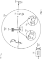
- Fig. 1 is a diagram illustrating a wireless network 100 in which aspects of the present disclosure may be practiced.
- the wireless network 100 may be an LTE network or some other wireless network, such as a 5G or NR network.
- the wireless network 100 may include a number of BSs 110 (shown as BS 110a, BS 110b, BS 110c, and BS 110d) and other network entities.
- a BS is an entity that communicates with user equipment (UEs) and may also be referred to as a base station, a NR BS, a Node B, a gNB, a 5G node B (NB), an access point, a transmit receive point (TRP), and/or the like.
- Each BS may provide communication coverage for a particular geographic area.
- the term "cell" can refer to a coverage area of a BS and/or a BS subsystem serving this coverage area, depending on the context in which the term is used.
- a BS may provide communication coverage for a macro cell, a pico cell, a femto cell, and/or another type of cell.
- a macro cell may cover a relatively large geographic area (e.g., several kilometers in radius) and may allow unrestricted access by UEs with service subscription.
- a pico cell may cover a relatively small geographic area and may allow unrestricted access by UEs with service subscription.
- a femto cell may cover a relatively small geographic area (e.g., a home) and may allow restricted access by UEs having association with the femto cell (e.g., UEs in a closed subscriber group (CSG)).
- a BS for a macro cell may be referred to as a macro BS.
- a BS for a pico cell may be referred to as a pico BS.
- a BS for a femto cell may be referred to as a femto BS or a home BS.
- a BS 110a may be a macro BS for a macro cell 102a
- a BS 110b may be a pico BS for a pico cell 102b
- a BS 110c may be a femto BS for a femto cell 102c.
- a BS may support one or multiple (e.g., three) cells.
- the terms "eNB”, “base station”, “NRBS”, “gNB”, “TRP”, “AP”, "node B", “5GNB”, and “cell” may be used interchangeably herein.
- a cell may not necessarily be stationary, and the geographic area of the cell may move according to the location of a mobile BS.
- the BSs may be interconnected to one another and/or to one or more other BSs or network nodes (not shown) in the wireless network 100 through various types of backhaul interfaces such as a direct physical connection, a virtual network, and/or the like using any suitable transport network.
- Wireless network 100 may also include relay stations.
- a relay station is an entity that can receive a transmission of data from an upstream station (e.g., a BS or a UE) and send a transmission of the data to a downstream station (e.g., a UE or a BS).
- a relay station may also be a UE that can relay transmissions for other UEs.
- a relay station 110d may communicate with macro BS 110a and a UE 120d in order to facilitate communication between BS 110a and UE 120d.
- a relay station may also be referred to as a relay BS, a relay base station, a relay, and/or the like.
- Wireless network 100 may be a heterogeneous network that includes BSs of different types, e.g., macro BSs, pico BSs, femto BSs, relay BSs, and/or the like. These different types of BSs may have different transmit power levels, different coverage areas, and different impacts on interference in wireless network 100.
- macro BSs may have a high transmit power level (e.g., 5 to 40 Watts) whereas pico BSs, femto BSs, and relay BSs may have lower transmit power levels (e.g., 0.1 to 2 Watts).
- a network controller 130 may couple to a set of BSs and may provide coordination and control for these BSs.
- Network controller 130 may communicate with the BSs via a backhaul.
- the BSs may also communicate with one another, e.g., directly or indirectly via a wireless or wireline backhaul.
- UEs 120 may be dispersed throughout wireless network 100, and each UE may be stationary or mobile.
- a UE may also be referred to as an access terminal, a terminal, a mobile station, a subscriber unit, a station, and/or the like.
- a UE may be a cellular phone (e.g., a smart phone), a personal digital assistant (PDA), a wireless modem, a wireless communication device, a handheld device, a laptop computer, a cordless phone, a wireless local loop (WLL) station, a tablet, a camera, a gaming device, a netbook, a smartbook, an ultrabook, a medical device or equipment, biometric sensors/devices, wearable devices (smart watches, smart clothing, smart glasses, smart wrist bands, smart jewelry (e.g., smart ring, smart bracelet)), an entertainment device (e.g., a music or video device, or a satellite radio), a vehicular component or sensor, smart meters/sensors, industrial manufacturing equipment, a global positioning system device, or any other suitable device that is configured to communicate via a wireless or wired medium.
- a cellular phone e.g., a smart phone
- PDA personal digital assistant
- WLL wireless local loop
- MTC and eMTC UEs include, for example, robots, drones, remote devices, sensors, meters, monitors, location tags, and/or the like, that may communicate with a base station, another device (e.g., remote device), or some other entity.
- a wireless node may provide, for example, connectivity for or to a network (e.g., a wide area network such as Internet or a cellular network) via a wired or wireless communication link.
- Some UEs may be considered Internet-ofThings (IoT) devices, and/or may be implemented as NB-IoT (narrowband internet of things) devices.
- Some UEs may be considered a Customer Premises Equipment (CPE).
- UE 120 may be included inside a housing that houses components of UE 120, such as processor components, memory components, and/or the like.
- any number of wireless networks may be deployed in a given geographic area.
- Each wireless network may support a particular RAT and may operate on one or more frequencies.
- a RAT may also be referred to as a radio technology, an air interface, and/or the like.
- a frequency may also be referred to as a carrier, a frequency channel, and/or the like.
- Each frequency may support a single RAT in a given geographic area in order to avoid interference between wireless networks of different RATs.
- NR or 5G RAT networks may be deployed.
- two or more UEs 120 may communicate directly using one or more sidelink channels (e.g., without using a base station 110 as an intermediary to communicate with one another).
- the UEs 120 may communicate using peer-to-peer (P2P) communications, device-to-device (D2D) communications, a vehicle-to-everything (V2X) protocol (e.g., which may include a vehicle-to-vehicle (V2V) protocol, a vehicle-to-infrastructure (V2I) protocol, and/or the like), a mesh network, and/or the like).
- V2X vehicle-to-everything
- the UE 120 may perform scheduling operations, resource selection operations, and/or other operations described elsewhere herein as being performed by the base station 110.
- Fig. 1 is provided as an example. Other examples may differ from what is described with regard to Fig. 1 .
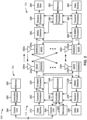
- Fig. 2 shows a block diagram of a design 200 of base station 110 and UE 120, which may be one of the base stations and one of the UEs in Fig. 1 .
- Base station 110 may be equipped with T antennas 234a through 234t
- UE 120 may be equipped with R antennas 252a through 252r, where in general T ⁇ 1 and R ⁇ 1.
- a transmit processor 220 may receive data from a data source 212 for one or more UEs, select one or more modulation and coding schemes (MCS) for each UE based at least in part on channel quality indicators (CQIs) received from the UE, process (e.g., encode and modulate) the data for each UE based at least in part on the MCS(s) selected for the UE, and provide data symbols for all UEs. Transmit processor 220 may also process system information (e.g., for semi-static resource partitioning information (SRPI) and/or the like) and control information (e.g., CQI requests, grants, upper layer signaling, and/or the like) and provide overhead symbols and control symbols.
- MCS modulation and coding schemes
- CQIs channel quality indicators
- Transmit processor 220 may also process system information (e.g., for semi-static resource partitioning information (SRPI) and/or the like) and control information (e.g., CQI requests, grants, upper layer signal
- Transmit processor 220 may also generate reference symbols for reference signals (e.g., the cell-specific reference signal (CRS)) and synchronization signals (e.g., the primary synchronization signal (PSS) and secondary synchronization signal (SSS)).
- a transmit (TX) multiple-input multiple-output (MIMO) processor 230 may perform spatial processing (e.g., precoding) on the data symbols, the control symbols, the overhead symbols, and/or the reference symbols, if applicable, and may provide T output symbol streams to T modulators (MODs) 232a through 232t. Each modulator 232 may process a respective output symbol stream (e.g., for OFDM and/or the like) to obtain an output sample stream.
- Each modulator 232 may further process (e.g., convert to analog, amplify, filter, and upconvert) the output sample stream to obtain a downlink signal.
- T downlink signals from modulators 232a through 232t may be transmitted via T antennas 234a through 234t, respectively.
- the synchronization signals can be generated with location encoding to convey additional information.
- antennas 252a through 252r may receive the downlink signals from base station 110 and/or other base stations and may provide received signals to demodulators (DEMODs) 254a through 254r, respectively.
- Each demodulator 254 may condition (e.g., filter, amplify, downconvert, and digitize) a received signal to obtain input samples.
- Each demodulator 254 may further process the input samples (e.g., for OFDM and/or the like) to obtain received symbols.
- a MIMO detector 256 may obtain received symbols from all R demodulators 254a through 254r, perform MIMO detection on the received symbols if applicable, and provide detected symbols.
- a receive processor 258 may process (e.g., demodulate and decode) the detected symbols, provide decoded data for UE 120 to a data sink 260, and provide decoded control information and system information to a controller/processor 280.
- a channel processor may determine reference signal received power (RSRP), received signal strength indicator (RSSI), reference signal received quality (RSRQ), channel quality indicator (CQI), and/or the like.
- RSRP reference signal received power
- RSSI received signal strength indicator
- RSRQ reference signal received quality indicator
- CQI channel quality indicator
- one or more components of UE 120 may be included in a housing.
- a transmit processor 264 may receive and process data from a data source 262 and control information (e.g., for reports comprising RSRP, RSSI, RSRQ, CQI, and/or the like) from controller/processor 280. Transmit processor 264 may also generate reference symbols for one or more reference signals. The symbols from transmit processor 264 may be precoded by a TX MIMO processor 266 if applicable, further processed by modulators 254a through 254r (e.g., for DFT-s-OFDM, CP-OFDM, and/or the like), and transmitted to base station 110.
- control information e.g., for reports comprising RSRP, RSSI, RSRQ, CQI, and/or the like
- Transmit processor 264 may also generate reference symbols for one or more reference signals.
- the symbols from transmit processor 264 may be precoded by a TX MIMO processor 266 if applicable, further processed by modulators 254a through 254r (e.g., for DFT-
- the uplink signals from UE 120 and other UEs may be received by antennas 234, processed by demodulators 232, detected by a MIMO detector 236 if applicable, and further processed by a receive processor 238 to obtain decoded data and control information sent by UE 120.
- Receive processor 238 may provide the decoded data to a data sink 239 and the decoded control information to controller/processor 240.
- Base station 110 may include communication unit 244 and communicate to network controller 130 via communication unit 244.
- Network controller 130 may include communication unit 294, controller/processor 290, and memory 292.
- Controller/processor 240 of base station 110, controller/processor 280 of UE 120, and/or any other component(s) of Fig. 2 may perform one or more techniques associated with time-division multiplexing of uplink communications during make-before-break handover, as described in more detail elsewhere herein.
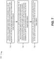
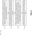
- controller/processor 240 of base station 110, controller/processor 280 of UE 120, and/or any other component(s) of Fig. 2 may perform or direct operations of, for example, process 600 of Fig. 6 , process 700 of Fig. 7 , process 800 of Fig. 8 , and/or other processes as described herein.
- Memories 242 and 282 may store data and program codes for base station 110 and UE 120, respectively.
- memory 242 and/or memory 282 may comprise a non-transitory computer-readable medium storing one or more instructions for wireless communication.
- the one or more instructions when executed by one or more processors of the base station 110 and/or the UE 120, may perform or direct operations of, for example, process 600 of Fig. 6 , process 700 of Fig. 7 , process 800 of Fig. 8 , and/or other processes as described herein.
- a scheduler 246 may schedule UEs for data transmission on the downlink and/or uplink.
- UE 120 may include means for determining a prioritization rule that indicates a relative priority for different uplink communications included in a group of uplink communications, wherein the group of uplink communications includes at least a first uplink communication and a second uplink communication to be transmitted by the UE 120 using time-division multiplexing during a make-before-break handover procedure; means for transmitting, based at least in part on the prioritization rule, the first uplink communication to a target base station and the second uplink communication to a source base station using time-division multiplexing during the make-before-break handover procedure; and/or the like.
- such means may include one or more components of UE 120 described in connection with Fig. 2 , such as controller/processor 280, transmit processor 264, TX MIMO processor 266, MOD 254, antenna 252, DEMOD 254, MIMO detector 256, receive processor 258, and/or the like.
- a source base station may include means for receiving, from a target base station, an indication of a set of resources available for uplink communications between a UE and the target base station during a make-before-break handover procedure; means for determining a timing for an uplink communication between the UE and the source base station during the make-before-break handover procedure based at least in part on the indication, wherein the timing does not conflict with the set of resources available for uplink communications between the UE and the target base station; means for transmitting a grant to the UE, wherein the grant indicates the timing for the uplink communication between the UE and the source base station; and/or the like.
- such means may include one or more components of base station 110 described in connection with Fig. 2 , such as antenna 234, DEMOD 232, MIMO detector 236, receive processor 238, controller/processor 240, transmit processor 220, TX MIMO processor 230, MOD 232, antenna 234, and/or the like.
- a target base station may include means for receiving, from a source base station, an indication of a first set of resources configured for uplink communications between a UE and the source base station during a make-before-break handover procedure; means for transmitting, to the source base station, an indication of a second set of resources available for uplink communications between the UE and the target base station during the make-before-break handover procedure; means for determining a timing for an uplink communication between the UE and the target base station during the make-before-break handover procedure based at least in part on the first set of resources and the second set of resources, wherein the timing does not conflict with the first set of resources; means for transmitting a grant to the UE, wherein the grant indicates the timing for the uplink communication between the UE and the target base station; and/or the like.
- such means may include one or more components of base station 110 described in connection with Fig. 2 , such as antenna 234, DEMOD 232, MIMO detector 236, receive processor 238, controller/processor 240, transmit processor 220, TX MIMO processor 230, MOD 232, antenna 234, and/or the like.
- Fig. 2 is provided as an example. Other examples may differ from what is described with regard to Fig. 2 .
- Fig. 3 is a diagram illustrating an example 300 of make-before-break handover, in accordance with various aspects of the present disclosure.
- a make-before-break (MBB) handover procedure may involve a UE 305, a source base station 310, a target base station 315, a user plane function (UPF) device 320, and an access and mobility management function (AMF) device 325.
- the UE 305 may correspond to the UE 120 described elsewhere herein.
- the source base station 310 and/or the target base station 315 may correspond to the base station 110 described elsewhere herein.
- the UPF device 320 and/or the AMF device 325 may correspond to the network controller 130 described elsewhere herein.
- the UE 305 and the source base station 310 may be connected (e.g., may have a radio resource control (RRC) connection) via a serving cell or a source cell, and the UE 305 may undergo a handover to the target base station 315 via a target cell.
- RRC radio resource control
- the UPF device 320 and/or the AMF device 325 may be located within a core network.
- the source base station 310 and the target base station 315 may be in communication with the core network for mobility support and user plane functions.
- the MBB handover procedure may include an enhanced MBB (eMBB) handover procedure.
- eMBB enhanced MBB
- the MBB handover procedure may include a handover preparation phase 330, a handover execution phase 335, and a handover completion phase 340.
- the UE 305 may report measurements that cause the source base station 310 and/or the target base station 315 to prepare for handover and trigger execution of the handover.
- the UE 305 may execute the handover by performing a random access procedure with the target base station 315 and establishing an RRC connection with the target base station 315.
- the source base station 310 may forward stored communications associated with the UE 305 to the target base station 315, and the UE 305 may be released from a connection with the source base station 310.
- the UE 305 may perform one or more measurements, and may transmit a measurement report to the source base station 310 based at least in part on performing the one or more measurements (e.g., serving cell measurements, neighbor cell measurements, and/or the like).
- the measurement report may indicate, for example, a reference signal received power (RSRP) parameter, a reference signal received quality (RSRQ) parameter, a received signal strength indicator (RSSI) parameter, a signal-to-interference-plus-noise-ratio (SINR) parameter, and/or the like (e.g., for the serving cell, one or more neighbor cells, and/or the like).
- RSRP reference signal received power
- RSSI received signal strength indicator
- SINR signal-to-interference-plus-noise-ratio
- the source base station 310 may use the measurement report to determine whether to trigger a handover to the target base station 315. For example, if one or more measurements satisfy a condition, then the source base station 310 may trigger a handover of the UE 305 to the target base station 315.
- the source base station 310 and the target base station 315 may communicate with one another to prepare for a handover of the UE 305.
- the source base station 310 may transmit a handover request to the target base station 315 to instruct the target base station 315 to prepare for the handover.
- the source base station 310 may communicate radio resource control (RRC) context information associated with the UE 305 and/or configuration information associated with the UE 305 to the target base station 315.
- RRC radio resource control
- the target base station 315 may prepare for the handover by reserving resources for the UE 305. After reserving the resources, the target base station 315 may transmit an acknowledgement (ACK) to the source base station 310 in response to the handover request.
- ACK acknowledgement
- the source base station 310 may transmit an RRC reconfiguration message to the UE 305.
- the RRC reconfiguration message may include a handover command instructing the UE 305 to execute a handover procedure from the source base station 310 to the target base station 315.
- the handover command may include information associated with the target base station 315, such as a random access channel (RACH) preamble assignment for accessing the target base station 315.
- RACH random access channel
- the UE 305 may execute the handover by performing a random access procedure with the target base station 315 (e.g., including synchronization with the target base station 315) while continuing to communicate with the source base station 310.
- the UE 305 may transmit uplink data, uplink control information, an uplink reference signal (e.g., a sounding reference signal), and/or the like to the source base station 310, and/or may receive downlink data, downlink control information, a downlink reference signal, and/or the like from the source base station 310.
- an uplink reference signal e.g., a sounding reference signal
- the UE may transmit an RRC reconfiguration completion message to the target base station 315. Reception of the RRC reconfiguration message by the target base station 315 may trigger the start of the handover completion phase 340.
- the source base station 310 and the target base station 315 may communicate with one another to prepare for release of the connection between the source base station 310 and the UE 305.
- the target base station 315 may determine that a connection between the source base station 310 and the UE 305 is to be released, such as after receiving the RRC reconfiguration message from the UE 305.
- the target base station 315 may transmit a handover connection setup completion message to the source base station 310.
- the handover connection setup completion message may cause the source base station 310 to stop transmitting data to the UE 305 and/or to stop receiving data from the UE 305.
- the handover connection setup completion message may cause the source base station 310 to forward communications associated with the UE 305 to the target base station 315 and/or to notify the target base station 315 of a status of one or more communications with the UE 305.
- the source base station 310 may forward, to the target base station 315, buffered downlink communications (e.g., downlink data) for the UE 305 and/or uplink communications (e.g., uplink data) received from the UE 305.
- buffered downlink communications e.g., downlink data
- uplink communications e.g., uplink data
- the source base station 310 may notify the target base station 315 regarding a packet data convergence protocol (PDCP) status associated with the UE 305, a sequence number to be used for a downlink communication with the UE 305, and/or the like.
- PDCP packet data convergence protocol
- the target base station 315 may transmit an RRC reconfiguration message to the UE 305 to instruct the UE 305 to release the connection with the source base station 310.
- the UE 305 may stop communicating with the source base station 310. For example, the UE 305 may refrain from transmitting uplink communications to the source base station 310 and/or may refrain from monitoring for downlink communications from the source base station 310.
- the UE may transmit an RRC reconfiguration completion message to the target base station 315 to indicate that the connection between the source base station 310 and the UE 305 is being released or has been released.
- the target base station 315, the UPF device 320, and/or the AMF device 325 may communicate to switch a user plane path of the UE 305 from the source base station 310 to the target base station 315.
- downlink communications for the UE 305 may be routed through the core network to the source base station 310.
- downlink communications for the UE 305 may be routed through the core network to the target base station 315.
- the AMF device 325 may transmit an end marker message to the source base station 310 to signal completion of the user plane path switch.
- the target base station 315 and the source base station 310 may communicate to release the source base station 310.
- the UE 305 may maintain simultaneous connections with the source base station 310 and the target base station 315 during a time period 395.
- the time period 395 may start at the beginning of the handover execution phase 335 (e.g., upon reception by the UE 305 of a handover command from the source base station 310) when the UE 305 performs a random access procedure with the target base station 315.
- the time period 395 may end upon release of the connection between the UE 305 and the source base station 310 (e.g., upon reception by the UE 305 of an instruction, from the target base station 315, to release the source base station 310).
- the handover procedure can be performed with zero or a minimal interruption to communications, thereby reducing latency.
- some UEs 305 may not be capable of performing simultaneous transmissions over two communication links.
- a UE 305 may include a single transmit chain, and thus can only transmit on one link at a time.
- a UE may include multiple transmit chains, but may not be able to transmit on both links due to an incompatible band combination (e.g., an intra-frequency handover) and/or interference issues.
- Some techniques and apparatuses described herein permit a UE 305 that cannot simultaneously transmit on different links to perform MBB handover with minimal interruption to communications, thereby reducing latency.
- the UE 305 may use time-division multiplexing (TDM) to transmit uplink communications via a first connection with the source base station 310 and a second connection with the target base station 315.
- TDM time-division multiplexing
- Some techniques and apparatuses described herein permit the UE 305 to transmit uplink communications using TDM according to a prioritization rule that prioritizes some communications over other communications to reduce latency and interruption time.
- some techniques and apparatuses described herein permit the UE 305 to use TDM for communications on different links in a dynamic manner, without being configured with a semi-static TDM pattern.
- TDM uplink transmission time interval
- Fig. 3 is provided as an example. Other examples may differ from what is described with respect to Fig. 3 .
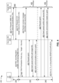
- Fig. 4 is a diagram illustrating an example 400 of time-division multiplexing of uplink communications during make-before-break handover, in accordance with various aspects of the present disclosure.
- an MBB handover procedure may involve a UE 305, a source base station 310, a target base station 315, UPF device 320, and an AMF device 325.
- the MBB handover procedure may include a handover preparation phase 330, a handover execution phase 335, and a handover completion phase 340.
- the UE 305 supports multiple layer 2 protocol stacks (e.g., at least two independent layer 2 protocol stacks) to support TDM of uplink communications via a first connection with the source base station 310 and a second connection with the target base station 315.
- the source base station 310 and the target base station 315 may communicate with one another to prepare for a handover of the UE 305, as described above in connection with reference number 350 of Fig. 3 .
- the source base station 310 may transmit, to the target base station 315, a handover request that instructs the target base station 315 to prepare for MBB handover.
- the handover request may include source resource coordination information.
- the source resource coordination information may indicate a first set of resources (e.g., time resources, frequency resources, physical resource blocks, spatial resources, and/or the like) configured for uplink communications between the UE 305 and the source base station 310 during the MBB handover procedure.
- the first set of resources may include one or more resources configured for a sounding reference signal (SRS) from the UE 305 to the source base station 310, one or more resources configured for a physical uplink control channel (PUCCH) communication from the UE 305 to the source base station 310, one or more resources configured for a physical uplink shared channel (PUSCH) communication from the UE 305 to the source base station 310, and/or the like.
- SRS sounding reference signal
- PUCCH physical uplink control channel
- PUSCH physical uplink shared channel
- the PUSCH communication may include a non-data communication, such as uplink control information (UCI), a channel state information (CSI) report, acknowledgement (ACK) or negative acknowledgement (NACK) feedback (collectively, ACK/NACK feedback), a radio link control (RLC) status report, and/or the like.
- UCI uplink control information
- CSI channel state information
- ACK acknowledgement
- NACK negative acknowledgement
- RLC radio link control
- the first set of resources may be configured for uplink control communications and/or uplink reference signals between the UE 305 and the source base station 310.
- the source base station 310 may configure the first set of resources for the UE 305, such as by using a configuration indicated in an RRC message.
- the target base station 315 may transmit, to the source base station 310, an ACK in response to the handover request (e.g., shown as a handover request ACK).
- the handover request ACK may include target resource coordination information.
- the target resource coordination information may indicate a second set of resources available for uplink communications between the UE 305 and the target base station 315 during the MBB handover procedure.
- the second set of resources may include one or more resources configured for UE 305 to perform a random access procedure with the target base station 315, such as one or more resources configured for an uplink random access message, a random access preamble, a random access payload, an uplink random access channel (RACH) message (sometimes referred to as an uplink physical RACH (PRACH) message), a PUSCH message transmitted during a random access procedure, msg1 of a four-step RACH procedure, msg3 of a four-step RACH procedure, msgA of a two-step RACH procedure, and/or the like.
- the target base station 315 may broadcast information that identifies the second set of resources in system information, such as a system information block (SIB).
- SIB system information block
- the source base station 310 and the target base station 315 may be synchronized. For example, communications and/or TTIs (e.g., subframes, slots, and/or the like) of the source base station 310 and the target base station 315 may be time-aligned. In this case, the source base station 310 and the target base station 315 may not need to account for timing mis-alignments when scheduling uplink communications.
- TTIs e.g., subframes, slots, and/or the like
- the source base station 310 may indicate, to the target base station 315 (e.g., in the handover request), a timing offset.
- the timing offset may indicate an offset in timing between the source base station 310 and the target base station 315 (e.g., a difference between TTI boundaries).
- the UE 305 may indicate a timing offset between the UE 305 and the target base station 315 and/or a timing offset between the source base station 310 and the target base station 315.
- the UE 305 may determine the timing offset based at least in part on a propagation delay observed between the UE 305 and one or both of the source base station 310 and the target base station 315.
- the source base station 310 may use this timing offset to identify the second set of resources (e.g., a set of time domain resources) available for uplink communications between the UE 305 and the target base station 315 during the MBB handover procedure.
- the source base station 310 may indicate the timing offset to the target base station 315, and the target base station 315 may use the timing offset when indicating the second set of resources to the source base station 310.
- the source base station 310 and the target base station 315 may use the same numerology (e.g., a sub-carrier spacing (SCS) and/or the like). In this case, the source base station 310 and the target base station 315 may not need to account for different numerologies when scheduling uplink communications.
- SCS sub-carrier spacing
- the source base station 310 and the target base station 315 may need to account for potential mis-alignments due to different numerologies when scheduling uplink communications.
- the source base station 310 may indicate, to the target base station 315 (e.g., in the handover request), a numerology being used for communications between the UE 305 and the source base station 310, one or more numerologies supported by the source base station 310 and/or the UE 305, and/or the like.
- the target base station 315 may indicate, to the source base station 310 (e.g., in the handover request ACK), one or more numerologies supported by the target base station 315.
- the source base station 310 and the target base station 315 may account for these numerologies when indicating the first set of resources, when indicating the second set of resources, when scheduling timing of uplink communications, and/or the like.
- the source base station 310 and the target base station 315 may determine to use a same numerology for such operations, such as a numerology supported by both the source base station 310 and the target base station 315, a numerology configured for communications between the UE 305 and the source base station 310, a lowest numerology between the source base station 310 and the target base station 315, and/or the like.
- the source base station 310 may transmit an RRC reconfiguration message to the UE 305.
- the RRC reconfiguration message may include a handover command instructing the UE 305 to execute an MBB handover procedure from the source base station 310 to the target base station 315.
- the RRC reconfiguration message may indicate that TDM is enabled for the MBB handover procedure.
- the source base station 310 may indicate that TDM is enabled for the MBB handover procedure based at least in part on a capability of the UE 305. For example, if the UE 305 does not support multiple transmit chains and/or multiple transmit antennas, then the source base station 310 may indicate that TDM is enabled for the MBB handover procedure.
- the source base station 310 may indicate that TDM is disabled for the MBB handover procedure. Reception of the handover command by the UE 305 may trigger the start of the handover execution phase 335, as described above in connection with reference number 355 of Fig. 3 .
- the UE 305 may determine a prioritization rule for prioritizing uplink communications with the source base station 310 and the target base station 315. In some aspects, the UE 305 may determine the prioritization rule based at least in part on receiving the handover command with the indication that TDM is enabled during MBB handover.
- the prioritization rule may be stored in memory of the UE 305 (e.g., rather than being signaled to the UE 305 by the base station 315).
- the prioritization rule may indicate a relative priority for different uplink communications included in a group of uplink communications to be transmitted by the UE 305 during the MBB handover procedure.
- the group of uplink communications may include a first uplink communication to be transmitted by the UE 305 to the target base station 315 using TDM during the MBB handover procedure.
- the group of uplink communications may further include a second uplink communication to be transmitted by the UE 305 to the source base station 310 using TDM during the MBB handover procedure.
- the group of uplink communications may include multiple uplink communications to be transmitted to the target base station 315 and/or multiple uplink communications to be transmitted to the source base station 310.
- the prioritization rule may indicate a relative priority for different types of uplink communications included in the group of uplink communications.
- the prioritization rule may indicate that uplink communications to the target base station 315 have a higher priority than uplink communications to the source base station 310 during the MBB handover procedure.
- the UE 305 may transmit the first uplink communication before the second uplink communication (e.g., using TDM), may transmit the first uplink communication before requesting a grant for the second uplink communication, may request a grant for the first uplink communication before transmitting the second uplink communication, may request a grant for the first uplink communication before requesting a grant for the second uplink communication, and/or the like.
- the prioritization rule may be different depending on a phase of the MBB handover procedure.
- the prioritization rule may include a first rule in the handover execution phase 335 before an RRC connection has been established between the UE 305 and the target base station 315, and may include a second rule in the handover completion phase 340 after an RRC connection has been established between the UE 305 and the target base station 315.
- the prioritization rule may indicate that, prior to establishment of an RRC connection between the UE 305 and the target base station 315 (e.g., during the handover execution phase 335), uplink random access communications with the target base station 315 have a higher priority than uplink communications with the source base station 310.
- an uplink random access communication may include a random access preamble, a random access payload, an uplink RACH message (sometimes referred to as an uplink PRACH message), a PUSCH message transmitted during a random access procedure, msg1 of a four-step RACH procedure, msg3 of a four-step RACH procedure, msgA of a two-step RACH procedure, and/or the like.
- the uplink communications with the source base station 310 may include uplink data communications (e.g., data communications on the PUSCH), SRSs, PUCCH communications, non-data communications on the PUSCH (e.g., UCI, a CSI report, ACK/NACK feedback, an RLC status report, and/or the like), and/or the like.
- the prioritization rule may indicate that uplink data communications to the source base station 310 have a higher priority (e.g., for TDM) than SRSs to the source base station 310, PUCCH communications to the source base station 310, non-data communications on the PUSCH to the source base station 310, and/or the like (e.g., during the handover execution phase 335).
- the prioritization rule may indicate that, after establishment of an RRC connection between the UE 305 and the target base station 315 (e.g., during the handover completion phase 340), uplink communications with the target base station 315 have a higher priority than uplink communications with the source base station 310.
- the uplink communications with the target base station 315 may include uplink data communications (e.g., data communications on the PUSCH), SRSs, PUCCH communications, non-data communications on the PUSCH (e.g., UCI, a CSI report, ACK/NACK feedback, an RLC status report, and/or the like), and/or the like.
- the prioritization rule may indicate that uplink data communications to the target base station 315 have a higher priority (e.g., for TDM) than SRSs to the target base station 315, PUCCH communications to the target base station 315, non-data communications on the PUSCH to the target base station 315, and/or the like (e.g., during the handover completion phase 340). Additionally, or alternatively, the prioritization rule may indicate that uplink communications to the source base station 310 are deactivated after establishment of an RRC connection between the UE 305 and the target base station 315 (e.g., during the handover completion phase 340).
- the UE 305 may prioritize uplink communications for the source base station 310 and/or the target base station 315 based at least in part on the prioritization rule during the handover execution phase 335. For example, as shown by reference number 430, the UE 305 may prioritize an uplink random access message to the target base station 315 over an uplink communication with the source base station 310 by transmitting the uplink random access message before (e.g., earlier in time than) the uplink communication and/or before a grant for the uplink communication. The UE 305 may prioritize communications using TDM to transmit higher priority communications before lower priority communications.
- the UE 305 may request a grant associated with an uplink communication with the source base station 310.
- the UE 305 may request the grant based at least in part on receiving an indication that TDM is enabled for the MBB procedure.
- the indication that TDM is enabled for the MBB procedure may indicate that the base stations 310, 315 will use grants to avoid scheduling or causing conflicting (e.g., simultaneous) uplink transmissions by the UE 305. In this way, TDM during the MBB handover procedure can be configured more flexibly than indicating a TDM pattern in the handover command.
- the source base station 310 may transmit a grant associated with the uplink communication based at least in part on receiving the request for the grant.
- the grant may indicate a timing for a corresponding uplink communication scheduled by the uplink grant, such as a PUSCH communication, a PUCCH communication (e.g., ACK/NACK feedback), and/or the like.
- the grant is an uplink grant for an uplink data communication (e.g., a PUSCH communication), and the uplink grant indicates a timing between the uplink grant and the uplink data communication (e.g., a k2 value).
- the grant may be a downlink grant for a downlink data communication (e.g., a PDSCH communication), and the downlink grant may indicate a timing between the downlink data communication and uplink ACK/NACK feedback (e.g., a k1 value).
- the source base station 310 may configure the timing (e.g., the k1 value, the k2 value, and/or the like) for the uplink communication to avoid the second set of resources available for uplink communications between the UE 305 and the target base station 315. In this way, scheduling conflicts can be avoided.
- the source base station 310 may determine the timing based at least in part on a timing offset with respect to the target base station 315 (described above), thereby avoiding scheduling conflicts when the source base station 310 and the target base station 315 are not synchronized. Additionally, or alternatively, the source base station 310 may determine the timing based at least in part on a tuning delay required for the UE 305 to switch between the source base station 310 (e.g., a serving cell) and the target base station 315 (e.g., a target cell). In some aspects, the UE 305 may indicate the tuning delay in a capability report (e.g., transmitted to the source base station 310).
- a capability report e.g., transmitted to the source base station 310.
- the UE 305 may transmit the uplink communication according to a timing indicated in the grant. Because the timing is coordinated between the source base station 310 and the target base station 315 to avoid scheduling conflicts, the UE 305 may be capable of using TDM for the uplink communication to the source base station 310 and one or more uplink communications to the target base station 315 (e.g., one or more random access messages, which may follow the random access message described in connection with reference number 430).
- TDM for the uplink communication to the source base station 310 and one or more uplink communications to the target base station 315 (e.g., one or more random access messages, which may follow the random access message described in connection with reference number 430).
- the UE 305 may prioritize uplink communications for the source base station 310 and/or the target base station 315 based at least in part on the prioritization rule during the handover completion phase 340. For example, as shown by reference number 455, the UE 305 may prioritize a first uplink communication with the target base station 315 over a second uplink communication with the source base station 310 by transmitting a grant for the first uplink communication before (e.g., earlier in time than) the second uplink communication and/or before a grant for the second uplink communication. The UE 305 may prioritize communications using TDM to transmit higher priority communications before lower priority communications. In some aspects, the UE 305 may request the grant based at least in part on receiving an indication that TDM is enabled for the MBB procedure, as described above.
- the target base station 315 may transmit a grant associated with the first uplink communication based at least in part on receiving the request for the grant.
- the grant may indicate a timing for a corresponding uplink communication scheduled by the uplink grant, such as a PUSCH communication, a PUCCH communication (e.g., ACK/NACK feedback), and/or the like.
- the grant is an uplink grant for an uplink data communication (e.g., a PUSCH communication), and the uplink grant indicates a timing between the uplink grant and the uplink data communication (e.g., a k2 value).
- the grant may be a downlink grant for a downlink data communication (e.g., a PDSCH communication), and the downlink grant may indicate a timing between the downlink data communication and uplink ACK/NACK feedback (e.g., a k1 value).
- the target base station 315 may configure the timing (e.g., the k1 value, the k2 value, and/or the like) for the uplink communication to avoid the first set of resources configured for uplink communications between the UE 305 and the source base station 310 during the MBB handover procedure. In this way, scheduling conflicts can be avoided.
- the target base station 315 may determine the timing based at least in part on a timing offset with respect to the source base station 310 (described above), thereby avoiding scheduling conflicts when the source base station 310 and the target base station 315 are not synchronized. Additionally, or alternatively, the target base station 315 may determine the timing based at least in part on a tuning delay required for the UE 305 to switch between the source base station 310 (e.g., a serving cell) and the target base station 315 (e.g., a target cell). In some aspects, the UE 305 may indicate the tuning delay in a capability report transmitted to the source base station 310, and the source base station 310 may indicate the tuning delay to the target base station 315 (e.g., in the handover request).
- a timing offset with respect to the source base station 310 described above
- the target base station 315 may determine the timing based at least in part on a tuning delay required for the UE 305 to switch between the source base station 310 (e.g.,
- the UE 305 may transmit the first uplink communication according to a timing indicated in the grant. Because the timing is coordinated between the source base station 310 and the target base station 315 to avoid scheduling conflicts, the UE 305 may be capable of using TDM for the first uplink communication with the target base station 315 and one or more uplink communications with the source base station 310 (e.g., which may be configured according to an RRC configuration message from the source base station 310 to the UE 305).
- TDM may be deactivated (e.g., disabled) after completion of a random access procedure with the target base station 315.
- TDM may be deactivated after the handover execution phase 335, during the handover completion phase 340, after an RRC connection between the UE 305 and the target base station 315 has been established, and/or the like.
- uplink communication from the UE 305 to the source base station 310 may be deactivated.
- uplink communications to the target base station 315 may be prioritized over uplink communications to the source base station 310 due to the deactivation of uplink communications to the source base station 310.
- TDM may remain active (e.g., activated, enabled, and/or the like) after completion of the random access procedure with the target base station 315 (e.g., after the handover execution phase 335, during the handover completion phase 340, after an RRC connection between the UE 305 and the target base station 315 has been established, and/or the like).
- a first uplink communication to the target base station 315 may be prioritized over a second uplink communication to the source base station 310 by transmitting the first uplink communication and/or a grant for the first uplink communication before transmitting the second uplink communication and/or a grant for the second uplink communication.
- the second uplink communication may include an SRS, a PUCCH communication, a PUSCH communication, and/or the like.
- the PUSCH communication may include a non-data communication, such as UCI, a CSI report, ACK/NACK feedback, an RLC status report, and/or the like.
- TDM and uplink communications to the source base station 310 may initially be deactivated upon completion of a random access procedure with the target base station 315. However, if the UE 305 does not receive an indication to release the connection with the source base station 310 prior to expiration of a timer (e.g., a dormancy timer), then TDM may be reactivated and the UE 305 may transmit one or more uplink communications to the source base station 310 (e.g., the second uplink communication described above). In some aspects, the timer may be initialized upon completion of the random access procedure with the target base station 315.
- a timer e.g., a dormancy timer
- the UE 305 may be permitted to perform the MBB handover with minimal interruption to communications even if the UE 305 cannot simultaneously transmit via a first connection with the source base station 310 and a second connection with the target base station 315. Furthermore, by following the prioritization rule(s) described herein for TDM, the UE 305 may reduce latency and interruption time during the MBB handover. Furthermore, the UE 305 may be permitted to use TDM for communications on different links in a dynamic manner without being configured with a semi-static TDM pattern, thereby reducing latency that may otherwise be caused by using a semi-statically configured TDM pattern.
- Fig. 4 is provided as an example. Other examples may differ from what is described with respect to Fig. 4 .
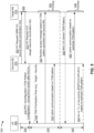
- Fig. 5 is a diagram illustrating another example of time-division multiplexing of uplink communications during make-before-break handover, in accordance with various aspects of the present disclosure.
- an MBB handover procedure may involve a UE 305, a source base station 310, a target base station 315, a UPF device 320, and an AMF device 325.
- the MBB handover procedure may include a handover preparation phase 330, a handover execution phase 335, and a handover completion phase 340.
- the source base station 310 and the target base station 315 may communicate with one another to prepare for a handover of the UE 305, as described above in connection with reference number 350 of Fig. 3 .
- the source base station 310 may transmit, to the target base station 315, a handover request that instructs the target base station 315 to prepare for MBB handover, as described above in connection with Fig. 4 .
- the target base station 315 may transmit, to the source base station 310, an ACK in response to the handover request (e.g., shown as a handover request ACK), as described above in connection with Fig. 4 .
- the source base station 310 may transmit an RRC reconfiguration message to the UE 305.
- the RRC reconfiguration message may include a handover command instructing the UE 305 to execute an MBB handover procedure from the source base station 310 to the target base station 315.
- the RRC reconfiguration message may indicate a TDM pattern configuration for TDM during the MBB handover procedure.
- the TDM pattern configuration may indicate a first set of resources available for uplink communications between the UE 305 and the target base station 315 and/or a second set of resources available for uplink communications between the UE 305 and the source base station 310.
- the source base station 310 and/or the target base station 315 may determine the TDM pattern configuration based at least in part on a first set of resources configured for uplink communications between the UE 305 and the source base station 310 during the MBB handover procedure and/or the second set of resources available for uplink communications between the UE 305 and the target base station 315 during the MBB handover procedure. Additionally, or alternatively, the source base station 310 and/or the target base station 315 may determine the TDM pattern configuration based at least in part on a timing offset between the source base station 310 and the target base station 315 and/or a numerology, as described above in connection with Fig. 4 .
- the source base station 310 and/or the target base station 315 may determine the TDM pattern configuration based at least in part on a tuning delay required for the UE 305 to switch between the source base station 310 (e.g., a serving cell) and the target base station 315 (e.g., a target cell).
- the UE 305 may indicate the tuning delay in a capability report (e.g., transmitted to the source base station 310).
- the source base station 310 may indicate the TDM pattern configuration based at least in part on a capability of the UE 305. For example, if the UE 305 does not support multiple transmit chains and/or multiple transmit antennas, then the source base station 310 may indicate the TDM pattern configuration. In some aspects, if the UE 305 supports multiple chains and/or multiple transmit antennas, then the source base station 310 may not indicate the TDM pattern configuration.
- the source base station 310 may indicate multiple TDM pattern configurations in the RRC reconfiguration message.
- the RRC reconfiguration message may include a first TDM pattern configuration to be used by the UE 305 during a random access procedure with the target base station 315 (e.g., prior to establishing an RRC connection with the target base station 315) and/or a second TDM pattern configuration to be used by the UE 305 after a random access procedure with the target base station 315 (e.g., after establishing an RRC connection with the target base station 315).
- the RRC reconfiguration message includes a single TDM pattern to be applied during the random access procedure and after the random access procedure.
- the UE 305 may determine a prioritization rule for prioritizing uplink communications with the source base station 310 and the target base station 315, as described above in connection with Fig. 4 .
- the UE 305 may determine the prioritization rule based at least in part on receiving the handover command with the TDM pattern configuration. Additional details regarding the prioritization rule are described above in connection with Fig. 4 .
- the UE 305 may prioritize uplink communications for the source base station 310 and/or the target base station 315 based at least in part on the prioritization rule during the handover execution phase 335. For example, as shown by reference number 530, the UE 305 may prioritize an uplink random access message to the target base station 315 over an uplink communication with the source base station 310 by transmitting the uplink random access message before (e.g., earlier in time than) the uplink communication and/or before a grant for the uplink communication. The UE 305 may prioritize communications using TDM to transmit higher priority communications before lower priority communications.
- the UE 305 may use the TDM pattern configuration (e.g., a TDM pattern configuration to be used during a random access procedure) to identify a set of resources to be used to transmit the uplink random access message to the target base station 315, and may transmit the uplink random access message to the target base station 315 in the identified set of resources.
- TDM pattern configuration e.g., a TDM pattern configuration to be used during a random access procedure
- the UE 305 may transmit an uplink communication to the source base station 310 based at least in part on the TDM pattern configuration (e.g., a TDM pattern configuration to be used during a random access procedure). For example, the UE 305 may use the TDM pattern configuration to identify a set of resources to be used to transmit the uplink communication to the source base station 310, and may transmit the uplink communication to the source base station 310 in the identified set of resources.
- the TDM pattern configuration e.g., a TDM pattern configuration to be used during a random access procedure.
- the UE 305 may use the TDM pattern configuration to identify a set of resources to be used to transmit the uplink communication to the source base station 310, and may transmit the uplink communication to the source base station 310 in the identified set of resources.
- the UE 305 may identify different sets of resources for the uplink random access message to the target base station 315 and for the uplink communication to the source base station 310, thereby avoiding conflicting (e.g., simultaneous) uplink transmissions by the UE 305.
- TDM during the MBB handover procedure can be configured with reduced signaling overhead and/or with less processing by the base stations 310, 315 to dynamically determine timing for uplink communications.
- the target base station 315 may instruct the UE 305 to switch the TDM pattern configuration being used.
- the TDM pattern configuration may be switched from a first TDM pattern configuration used during a random access procedure to a second TDM pattern configuration used after the random access procedure is complete.
- the instruction to switch the TDM pattern configuration may be indicated in a medium access control (MAC) control element (CE) (collectively, MAC-CE).
- MAC-CE medium access control control element
- the instruction to switch the TDM pattern configuration may be transmitted after the random access procedure is complete (e.g., after completion of the handover execution phase 335).
- the UE 305 may prioritize uplink communications for the source base station 310 and/or the target base station 315 based at least in part on the prioritization rule during the handover completion phase 340. For example, as shown by reference number 550, the UE 305 may prioritize a first uplink communication with the target base station 315 over a second uplink communication with the source base station 310 by transmitting the first uplink communication and/or a grant for the first uplink communication before (e.g., earlier in time than) the second uplink communication and/or before a grant for the second uplink communication. The UE 305 may prioritize communications using TDM to transmit higher priority communications before lower priority communications.
- the UE 305 may use the TDM pattern configuration (e.g., a TDM pattern configuration to be used after a random access procedure) to identify a set of resources to be used to transmit the first uplink communication to the target base station 315, and may transmit the first uplink communication to the target base station 315 in the identified set of resources.
- the TDM pattern configuration e.g., a TDM pattern configuration to be used after a random access procedure
- TDM may be deactivated (e.g., disabled) after completion of a random access procedure with the target base station 315, as described above in connection with Fig. 4 .
- TDM may be deactivated.
- uplink communications from the UE 305 to the source base station 310 may be deactivated.
- uplink communications to the target base station 315 may be prioritized over uplink communications to the source base station 310 due to the deactivation of uplink communications to the source base station 310.
- TDM may remain active (e.g., activated, enabled, and/or the like) after completion of the random access procedure with the target base station 315, as described above in connection with Fig. 4 .
- a first uplink communication to the target base station 315 may be prioritized over a second uplink communication to the source base station 310 by transmitting the first uplink communication and/or a grant for the first uplink communication before transmitting the second uplink communication and/or a grant for the second uplink communication.
- the second uplink communication may include an SRS, a PUCCH communication, a PUSCH communication, and/or the like.
- the PUSCH communication may include a non-data communication, such as UCI, a CSI report, ACK/NACK feedback, an RLC status report, and/or the like.
- TDM and uplink communications to the source base station 310 may initially be deactivated upon completion of a random access procedure with the target base station 315. However, if the UE 305 does not receive an indication to release the connection with the source base station 310 prior to expiration of a timer (e.g., a dormancy timer), then TDM may be reactivated and the UE 305 may transmit one or more uplink communications to the source base station 310 (e.g., the second uplink communication described above). In some aspects, the timer may be initialized upon completion of the random access procedure with the target base station 315.
- a timer e.g., a dormancy timer
- the UE 305 may be permitted to perform the MBB handover with minimal interruption to communications, even if the UE 305 cannot simultaneously transmit via a first connection with the source base station 310 and a second connection with the target base station 315. Furthermore, by following the prioritization rule(s) described herein for TDM, the UE 305 may reduce latency and interruption time during the MBB handover.
- the UE 305 may be permitted to use TDM for communications using a semi-statically-configured TDM pattern, thereby reducing signaling overhead and/or conserving base station resources (e.g., processing resources, memory resources, and/or the like) as compared to using a dynamically-configured timing for uplink TDM communications.
- base station resources e.g., processing resources, memory resources, and/or the like
- Fig. 5 is provided as an example. Other examples may differ from what is described with respect to Fig. 5 .
- Fig. 6 is a diagram illustrating an example process 600 performed, for example, by a UE, in accordance with various aspects of the present disclosure.
- Example process 600 is an example where a UE (e.g., UE 120, UE 305, and/or the like) performs operations associated with time-division multiplexing of uplink communications during make-before-break handover.
- a UE e.g., UE 120, UE 305, and/or the like
- process 600 may include determining a prioritization rule that indicates a relative priority for different uplink communications included in a group of uplink communications, wherein the group of uplink communications includes at least a first uplink communication and a second uplink communication to be transmitted by the UE using time-division multiplexing during a make-before-break handover procedure (block 610).
- the UE e.g., using receive processor 258, transmit processor 264, controller/processor 280, memory 282, and/or the like
- the group of uplink communications includes at least a first uplink communication and a second uplink communication to be transmitted by the UE using time-division multiplexing during a make-before-break handover procedure.
- process 600 may include transmitting, based at least in part on the prioritization rule, the first uplink communication to a target base station and the second uplink communication to a source base station using time-division multiplexing during the make-before-break handover procedure (block 620).
- the UE e.g., using transmit processor 264, controller/processor 280, memory 282, and/or the like
- Process 600 may include additional aspects, such as any single aspect or any combination of aspects described below and/or in connection with one or more other processes described elsewhere herein.
- process 600 includes requesting a grant for at least one of the first uplink communication with the target base station or the second uplink communication with the source base station based at least in part on the prioritization rule.
- process 600 includes receiving, from the source base station, an indication of a time-division multiplexing pattern configuration to be used for the time-division multiplexing, and the first uplink communication and the second uplink communication are transmitted further based at least in part on the time-division multiplexing pattern configuration.
- the prioritization rule is based at least in part on whether a radio resource control connection has been established between the UE and the target base station.
- the prioritization rule indicates that, prior to establishment of a radio resource control connection between the UE and the target base station, uplink random access communications with the target base station have a higher priority than uplink communications with the source base station.
- the prioritization rule indicates that, after establishment of a radio resource control connection between the UE and the target base station, uplink communications with the target base station have a higher priority than uplink communications with the source base station.
- process 600 includes transmitting, to the source base station, an indication of a timing offset with respect to the target base station.
- the time-division multiplexing is deactivated after completion of a random access procedure with the target base station, and uplink channels are deactivated for communications between the UE and the source base station based at least in part on deactivating the time-division multiplexing.
- the time-division multiplexing is reactivated after the deactivation based at least in part on a determination that the UE has not received an indication to release a connection with the source base station prior to expiration of a timer.
- the time-division multiplexing is active after completion of a random access procedure with the target base station, and the UE is configured to transmit at least one of a sounding reference signal, a physical uplink control channel communication, or a physical uplink shared channel communication to both the target base station and the source base station while the time-division multiplexing is active.
- the physical uplink shared channel communication includes at least one of a non-data communication, uplink control information, a channel state information report, acknowledgement or negative acknowledgement feedback, a radio link control status report, or a combination thereof.
- process 600 may include additional blocks, fewer blocks, different blocks, or differently arranged blocks than those depicted in Fig. 6 . Additionally, or alternatively, two or more of the blocks of process 600 may be performed in parallel.
- Fig. 7 is a diagram illustrating an example process 700 performed, for example, by a source base station, in accordance with various aspects of the present disclosure.
- Example process 700 is an example where a source base station (e.g., base station 110, source base station 310, and/or the like) performs operations associated with time-division multiplexing of uplink communications during make-before-break handover.
- a source base station e.g., base station 110, source base station 310, and/or the like
- process 700 may include receiving, from a target base station, an indication of a set of resources available for uplink communications between a UE and the target base station during a make-before-break handover procedure (block 710).
- the source base station e.g., using receive processor 238, controller/processor 240, memory 242, and/or the like
- process 700 may include determining a timing for an uplink communication between the UE and the source base station during the make-before-break handover procedure based at least in part on the indication, wherein the timing does not conflict with the set of resources available for uplink communications between the UE and the target base station (block 720).
- the source base station e.g., using transmit processor 220, receive processor 238, controller/processor 240, memory 242, and/or the like
- the timing does not conflict with the set of resources available for uplink communications between the UE and the target base station.
- process 700 may include transmitting a grant to the UE, wherein the grant indicates the timing for the uplink communication between the UE and the source base station (block 730).
- the source base station e.g., using transmit processor 220, controller/processor 240, memory 242, and/or the like
- the grant indicates the timing for the uplink communication between the UE and the source base station.
- Process 700 may include additional aspects, such as any single aspect or any combination of aspects described below and/or in connection with one or more other processes described elsewhere herein.
- process 700 includes transmitting, to the UE, a configuration message that indicates that time-division multiplexing is enabled for the make-before-break handover procedure.
- process 700 includes receiving, from the UE, a request for the grant during the make-before-break handover procedure and based at least in part on transmitting the configuration message.
- the grant is an uplink grant
- the uplink communication is an uplink data communication
- the timing is between the uplink grant and the uplink data communication.
- the grant is a downlink grant
- the uplink communication is ACK/NACK feedback
- the timing is between a downlink communication scheduled by the grant and the ACK/NACK feedback.
- process 700 includes receiving, from the UE, an indication of a timing offset with respect to the target base station; and identifying the set of resources based at least in part on the timing offset.
- process 700 includes transmitting an indication of the timing offset to the target base station, and the set of resources are based at least in part on the timing offset.
- process 700 includes transmitting an indication of a numerology, configured for communications between the source base station and the UE, to the target base station, and the set of resources are based at least in part on the numerology.
- the set of resources includes a set of random access channel resources configured for the target base station.
- process 700 may include additional blocks, fewer blocks, different blocks, or differently arranged blocks than those depicted in Fig. 7 . Additionally, or alternatively, two or more of the blocks of process 700 may be performed in parallel.
- Fig. 8 is a diagram illustrating an example process 800 performed, for example, by a target base station, in accordance with various aspects of the present disclosure.
- Example process 800 is an example where a target base station (e.g., base station 110, target base station 315, and/or the like) performs operations associated with time-division multiplexing of uplink communications during make-before-break handover.
- a target base station e.g., base station 110, target base station 315, and/or the like
- process 800 may include receiving, from a source base station, an indication of a first set of resources configured for uplink communications between a UE and the source base station during a make-before-break handover procedure (block 810).
- the target base station e.g., using receive processor 238, controller/processor 240, memory 242, and/or the like
- process 800 may include transmitting, to the source base station, an indication of a second set of resources available for uplink communications between the UE and the target base station during the make-before-break handover procedure (block 820).
- the target base station e.g., using transmit processor 220, controller/processor 240, memory 242, and/or the like
- process 800 may include determining a timing for an uplink communication between the UE and the target base station during the make-before-break handover procedure based at least in part on the first set of resources and the second set of resources, wherein the timing does not conflict with the first set of resources (block 830).
- the target base station e.g., using transmit processor 220, receive processor 238, controller/processor 240, memory 242, and/or the like
- the timing does not conflict with the first set of resources.
- process 800 may include transmitting a grant to the UE, wherein the grant indicates the timing for the uplink communication between the UE and the target base station (block 840).
- the target base station e.g., using transmit processor 220, controller/processor 240, memory 242, and/or the like
- the grant indicates the timing for the uplink communication between the UE and the target base station.
- Process 800 may include additional aspects, such as any single aspect or any combination of aspects described below and/or in connection with one or more other processes described elsewhere herein.
- the grant is transmitted based at least in part on receiving a UE request for the grant during the make-before-break handover procedure.
- the grant is an uplink grant
- the uplink communication is an uplink data communication
- the timing is between the uplink grant and the uplink data communication.
- the grant is a downlink grant
- the uplink communication is ACK/NACK feedback
- the timing is between a downlink communication scheduled by the grant and the ACK/NACK feedback.
- process 800 includes receiving an indication of a timing offset with respect to the source base station; and identifying the second set of resources based at least in part on the timing offset.
- process 800 includes receiving an indication of a numerology configured for communications between the source base station and the UE, and identifying the second set of resources based at least in part on the numerology.
- the second set of resources includes a set of random access channel resources configured for the target base station.
- the first set of resources includes one or more resources configured for at least one of a sounding reference signal configured for the source base station and the UE, a physical uplink control channel communication configured for the source base station and the UE, or a physical uplink shared channel communication configured for the source base station and the UE.
- the physical uplink shared channel communication includes at least one of a non-data communication, uplink control information, a channel state information report, acknowledgement or negative acknowledgement feedback, a radio link control status report, or a combination thereof.
- process 800 may include additional blocks, fewer blocks, different blocks, or differently arranged blocks than those depicted in Fig. 8 . Additionally, or alternatively, two or more of the blocks of process 800 may be performed in parallel.
- ком ⁇ онент is intended to be broadly construed as hardware, firmware, and/or a combination of hardware and software.
- a processor is implemented in hardware, firmware, and/or a combination of hardware and software.
- satisfying a threshold may, depending on the context, refer to a value being greater than the threshold, greater than or equal to the threshold, less than the threshold, less than or equal to the threshold, equal to the threshold, not equal to the threshold, and/or the like.
- "at least one of: a, b, or c” is intended to cover a, b, c, a-b, a-c, b-c, and a-b-c, as well as any combination with multiples of the same element (e.g., a-a, a-a-a, a-a-b, a-a-c, a-b-b, a-c-c, b-b, b-b-b, b-b-c, c-c, and c-c-c or any other ordering of a, b, and c).
Landscapes
- Engineering & Computer Science (AREA)
- Signal Processing (AREA)
- Computer Networks & Wireless Communication (AREA)
- Mobile Radio Communication Systems (AREA)
Claims (15)
- Verfahren (600) zur drahtlosen Kommunikation, das von einem Benutzergerät, UE, ausgeführt wird, umfassend:Bestimmen (610) einer Priorisierungsregel, die eine relative Priorität für verschiedene Uplink-Kommunikationen angibt, die in einer Gruppe von Uplink-Kommunikationen enthalten sind, wobei die Gruppe von Uplink-Kommunikationen zumindest eine erste Uplink-Kommunikation und eine zweite Uplink-Kommunikation enthält, die von dem UE unter Verwendung von Zeitmultiplexing während eines Make-Before-Break-Handover-Verfahrens zu übertragen sind; undÜbertragen (620), zumindest teilweise basierend auf der Priorisierungsregel, der ersten Uplink-Kommunikation an eine Zielbasisstation und der zweiten Uplink-Kommunikation an eine Quellbasisstation unter Verwendung von Zeitmultiplexing während des Make-Before-Break-Handover-Verfahrens.
- Verfahren gemäß Anspruch 1, wobei die Priorisierungsregel angibt, dass vor dem Aufbau einer Funkressourcenkontrollverbindung zwischen dem UE und der Zielbasisstation Uplink-Direktzugriffskommunikationen mit der Zielbasisstation eine höhere Priorität haben als Uplink-Kommunikationen mit der Quellbasisstation.
- Verfahren gemäß Anspruch 1, wobei die Priorisierungsregel angibt, dass nach dem Aufbau einer Funkressourcenkontrollverbindung zwischen dem UE und der Zielbasisstation Uplink-Kommunikationen mit der Zielbasisstation eine höhere Priorität haben als Uplink-Kommunikationen mit der Quellbasisstation.
- Verfahren gemäß Anspruch 1, weiterhin umfassend das Anfordern eines Grant für zumindest eine der ersten Uplink-Kommunikation mit der Zielbasisstation oder der zweiten Uplink-Kommunikation mit der Quellbasisstation, zumindest teilweise basierend auf der Priorisierungsregel.
- Verfahren gemäß Anspruch 1, weiterhin umfassend das Empfangen, von der Quellbasisstation, einer Angabe einer Zeitmultiplexmuster-Konfiguration, die für das Zeitmultiplexing verwendet werden soll, wobei die erste Uplink-Kommunikation und die zweite Uplink-Kommunikation weiterhin zumindest teilweise basierend auf der Zeitmultiplexmuster-Konfiguration übertragen werden.
- Verfahren gemäß Anspruch 1, wobei die Priorisierungsregel zumindest teilweise darauf basiert, ob eine Funkressourcenkontrollverbindung zwischen dem UE und der Zielbasisstation aufgebaut wurde.
- Verfahren gemäß Anspruch 1, weiterhin umfassend das Übertragen, an die Quellbasisstation, einer Angabe eines Zeitversatzes in Bezug auf die Zielbasisstation.
- Verfahren gemäß Anspruch 1, wobei das Zeitmultiplexing nach Abschluss eines Direktzugriffsverfahrens mit der Zielbasisstation deaktiviert wird und Uplink-Kanäle für Kommunikationen zwischen dem UE und der Quellbasisstation deaktiviert werden, zumindest teilweise basierend auf dem Deaktivieren des Zeitmultiplexens.
- Verfahren gemäß Anspruch 8, wobei das Zeitmultiplexing nach der Deaktivierung reaktiviert wird, zumindest teilweise basierend auf einer Bestimmung, dass das UE keine Angabe empfangen hat, eine Verbindung mit der Quellbasisstation vor Ablauf eines Timers freizugeben.
- Verfahren gemäß Anspruch 1, wobei das Zeitmultiplexing nach Abschluss eines Direktzugriffsverfahrens mit der Zielbasisstation aktiv ist und das UE konfiguriert ist, um zumindest eines von einem Sondierungsreferenzsignal, einer physikalischen Uplink-Kontrollkanalkommunikation oder einer gemeinsamen physikalischen Uplink-Kanalkommunikation an sowohl die Zielbasisstation als auch die Quellbasisstation zu übertragen, während das Zeitmultiplexing aktiv ist.
- Verfahren gemäß Anspruch 10, wobei die gemeinsame physikalische Uplink-Kanalkommunikation zumindest eines von einer Nicht-Datenkommunikation, Uplink-Kontrollinformation, einem Kanalzustandsinformationsbericht, einer Bestätigungs- oder negativen Bestätigungsrückmeldung, einem Funkverbindungskontrollstatusbericht oder einer Kombination davon enthält.
- Benutzergerät, UE, zur drahtlosen Kommunikation, umfassend:Mittel zum Bestimmen (280) einer Priorisierungsregel, die eine relative Priorität für verschiedene Uplink-Kommunikationen angibt, die in einer Gruppe von Uplink-Kommunikationen enthalten sind, wobei die Gruppe von Uplink-Kommunikationen zumindest eine erste Uplink-Kommunikation und eine zweite Uplink-Kommunikation enthält, die von dem UE unter Verwendung von Zeitmultiplexing während eines Make-Before-Break-Handover-Verfahrens zu übertragen sind; undMittel zum Übertragen (264), zumindest teilweise basierend auf der Priorisierungsregel, der ersten Uplink-Kommunikation an eine Zielbasisstation und der zweiten Uplink-Kommunikation an eine Quellbasisstation unter Verwendung von Zeitmultiplexing während des Make-Before-Break-Handover-Verfahrens.
- UE gemäß Anspruch 12, weiterhin umfassend:
Mittel zum Anfordern eines Grant für zumindest eine der ersten Uplink-Kommunikation mit der Zielbasisstation oder der zweiten Uplink-Kommunikation mit der Quellbasisstation, zumindest teilweise basierend auf der Priorisierungsregel. - UE gemäß Anspruch 12, weiterhin umfassend:
Mittel zum Empfangen, von der Quellbasisstation, einer Angabe einer Zeitmultiplexmuster-Konfiguration, die für das Zeitmultiplexing verwendet werden soll, wobei die erste Uplink-Kommunikation und die zweite Uplink-Kommunikation weiterhin zumindest teilweise basierend auf der Zeitmultiplexmuster-Konfiguration übertragen werden. - Computerprogramm, umfassend Code, der, wenn er von einem Prozessor eines Benutzergeräts, UE, ausgeführt wird, das UE veranlasst, Verfahren gemäß einem der Ansprüche 1-11 auszuführen.
Applications Claiming Priority (3)
| Application Number | Priority Date | Filing Date | Title |
|---|---|---|---|
| US201962880354P | 2019-07-30 | 2019-07-30 | |
| US16/928,705 US11895694B2 (en) | 2019-07-30 | 2020-07-14 | Time-division multiplexing of uplink communications during make-before-break handover |
| PCT/US2020/042088 WO2021021440A1 (en) | 2019-07-30 | 2020-07-15 | Time-division multiplexing of uplink communications during make-before-break handover |
Publications (2)
| Publication Number | Publication Date |
|---|---|
| EP4005275A1 EP4005275A1 (de) | 2022-06-01 |
| EP4005275B1 true EP4005275B1 (de) | 2024-08-21 |
Family
ID=71995078
Family Applications (1)
| Application Number | Title | Priority Date | Filing Date |
|---|---|---|---|
| EP20753536.0A Active EP4005275B1 (de) | 2019-07-30 | 2020-07-15 | Zeitmultiplexing von uplink-kommunikationen während eines make-before-break-handover |
Country Status (4)
| Country | Link |
|---|---|
| US (2) | US11895694B2 (de) |
| EP (1) | EP4005275B1 (de) |
| CN (2) | CN114145039B (de) |
| WO (1) | WO2021021440A1 (de) |
Families Citing this family (4)
| Publication number | Priority date | Publication date | Assignee | Title |
|---|---|---|---|---|
| US11895694B2 (en) | 2019-07-30 | 2024-02-06 | Qualcomm Incorporated | Time-division multiplexing of uplink communications during make-before-break handover |
| US20220279396A1 (en) * | 2019-08-02 | 2022-09-01 | Nec Corporation | Methods, devices and computer readable media for simultaneous connectivity based handover |
| CN112789892B (zh) * | 2019-09-11 | 2022-04-22 | 华为技术有限公司 | 无线通信方法、装置及系统 |
| WO2021062829A1 (zh) * | 2019-09-30 | 2021-04-08 | 华为技术有限公司 | 信道冲突处理方法及装置 |
Family Cites Families (17)
| Publication number | Priority date | Publication date | Assignee | Title |
|---|---|---|---|---|
| WO2011103722A1 (zh) * | 2010-02-26 | 2011-09-01 | 高通股份有限公司 | 通信系统中跨小区切换的方法和装置 |
| CN103428763B (zh) * | 2012-05-22 | 2018-05-04 | 中兴通讯股份有限公司 | 无线链路帧偏的纠正方法及装置 |
| EP3100563B1 (de) | 2014-01-28 | 2020-01-22 | HFI Innovation Inc. | Tdm-ul-übertragung auf mehreren versorgenden zellen für eine mobilstation mit einzelsender |
| US10772021B2 (en) | 2014-12-05 | 2020-09-08 | Qualcomm Incorporated | Low latency and/or enhanced component carrier discovery for services and handover |
| EP3131335B1 (de) * | 2015-08-14 | 2018-05-16 | Alcatel Lucent | Übergabe |
| DE112017004034T5 (de) | 2016-08-09 | 2019-06-13 | Intel IP Corporation | X2 support für verbesserte mobilität (emob) |
| KR102063084B1 (ko) | 2016-09-27 | 2020-01-07 | 엘지전자 주식회사 | 무선 통신 시스템에서 장치 대 장치 통신 단말의 동기 신호 송수신 방법 및 장치 |
| AU2018239358B2 (en) | 2017-03-24 | 2022-07-14 | Sharp Kabushiki Kaisha | Radio resource control (RRC) messages for enhanced scheduling request |
| US10485048B2 (en) | 2017-06-15 | 2019-11-19 | Apple Inc. | TDM transmission for inter-RAT dual connectivity UE |
| KR20200111788A (ko) * | 2018-01-31 | 2020-09-29 | 광동 오포 모바일 텔레커뮤니케이션즈 코포레이션 리미티드 | 데이터 전송 방법, 핸드오버 방법 및 관련 기기 |
| US10687263B2 (en) | 2018-02-15 | 2020-06-16 | Qualcomm Incorporated | Enhanced make-before-break handover |
| WO2019200603A1 (en) * | 2018-04-20 | 2019-10-24 | Zte Corporation | Apparatus and method for mobility management |
| US12022335B2 (en) * | 2018-09-27 | 2024-06-25 | Apple Inc. | UE capability indication for multi-connectivity handover |
| CN113424585B (zh) * | 2019-02-11 | 2024-10-18 | 诺基亚技术有限公司 | 利用网络切片的蜂窝部署中的增强型移动性 |
| WO2020167230A1 (en) * | 2019-02-14 | 2020-08-20 | Telefonaktiebolaget Lm Ericsson (Publ) | Source access node, target access node and methods for enhanced handover |
| CN114828116B (zh) * | 2019-02-15 | 2025-07-04 | 华为技术有限公司 | 一种终端信息的通信处理方法和相关设备 |
| US11895694B2 (en) | 2019-07-30 | 2024-02-06 | Qualcomm Incorporated | Time-division multiplexing of uplink communications during make-before-break handover |
-
2020
- 2020-07-14 US US16/928,705 patent/US11895694B2/en active Active
- 2020-07-15 CN CN202080052850.XA patent/CN114145039B/zh active Active
- 2020-07-15 WO PCT/US2020/042088 patent/WO2021021440A1/en not_active Ceased
- 2020-07-15 CN CN202410651182.2A patent/CN118474813A/zh active Pending
- 2020-07-15 EP EP20753536.0A patent/EP4005275B1/de active Active
-
2024
- 2024-01-10 US US18/409,100 patent/US12289757B2/en active Active
Also Published As
| Publication number | Publication date |
|---|---|
| EP4005275A1 (de) | 2022-06-01 |
| US12289757B2 (en) | 2025-04-29 |
| US11895694B2 (en) | 2024-02-06 |
| US20240147520A1 (en) | 2024-05-02 |
| WO2021021440A1 (en) | 2021-02-04 |
| US20210037547A1 (en) | 2021-02-04 |
| CN114145039A (zh) | 2022-03-04 |
| CN114145039B (zh) | 2024-06-07 |
| CN118474813A (zh) | 2024-08-09 |
Similar Documents
| Publication | Publication Date | Title |
|---|---|---|
| WO2020119621A1 (en) | Conditional handover procedure signaling | |
| WO2020119597A1 (en) | Cell and beam selection for conditional handover procedure | |
| EP4614821A2 (de) | Doppelaktive protokollstapelübergabe für benutzergerät | |
| WO2020103664A1 (en) | Random access channel (rach) -less procedure | |
| EP4091283B1 (de) | Verfahren zur bestimmung einer verzögerung für downlink-steuerungsinformationen auf der basis der aktivierung/deaktivierung von sekundärzellen | |
| US12289757B2 (en) | Time-division multiplexing of uplink communications during make-before-break handover | |
| EP3967091B1 (de) | Planungskonfiguration für den betrieb von mehrfeldantennen auf der grundlage der mehrfeldantennenfähigkeit des benutzergeräts | |
| EP4042746B1 (de) | Bandbreitenteilumschaltung für eine übergabe mit zwei aktiven protokollstacks | |
| EP4014551B1 (de) | Uplink-umschaltung für erhöhte mobilität | |
| EP4073965A1 (de) | Harq-rückkopplung für eine auf dci-basis basierende strahlkonfiguration und/oder pfadverlustreferenzsignalkonfiguration | |
| EP3991480A1 (de) | Übertragungsleistungssteuerung | |
| EP3963793A1 (de) | Gemeinsame nutzung von dynamischen physikalischen downling-steuerkanal (pdcch)-ressourcen zwischen pdcch-überwachung und pdcch-übertragung in einem multihop-netzwerk | |
| KR20210146936A (ko) | 사용자 장비 능력-기반 전환 | |
| US11533219B2 (en) | Prioritizing procedures for transmission of a beam failure recovery request via a secondary cell used for carrier aggregation | |
| US11363543B2 (en) | Transmit power determination in dual-active-protocol stack handover | |
| WO2021068869A1 (en) | Two-step random access channel signaling | |
| WO2021007829A1 (en) | Scell measurement configuration | |
| EP4111783B1 (de) | Vorkonfigurierte aktivierung und deaktivierung | |
| AU2020308330B2 (en) | Feedback message control | |
| WO2021162772A1 (en) | Coordinating overheating assistance information in a dual connectivity configuration | |
| US11665558B2 (en) | Beam failure recovery request multiplexing for secondary cells | |
| US20220046431A1 (en) | Cell and full duplex beam pair updating |
Legal Events
| Date | Code | Title | Description |
|---|---|---|---|
| STAA | Information on the status of an ep patent application or granted ep patent |
Free format text: STATUS: UNKNOWN |
|
| STAA | Information on the status of an ep patent application or granted ep patent |
Free format text: STATUS: THE INTERNATIONAL PUBLICATION HAS BEEN MADE |
|
| PUAI | Public reference made under article 153(3) epc to a published international application that has entered the european phase |
Free format text: ORIGINAL CODE: 0009012 |
|
| STAA | Information on the status of an ep patent application or granted ep patent |
Free format text: STATUS: REQUEST FOR EXAMINATION WAS MADE |
|
| 17P | Request for examination filed |
Effective date: 20211228 |
|
| AK | Designated contracting states |
Kind code of ref document: A1 Designated state(s): AL AT BE BG CH CY CZ DE DK EE ES FI FR GB GR HR HU IE IS IT LI LT LU LV MC MK MT NL NO PL PT RO RS SE SI SK SM TR |
|
| DAV | Request for validation of the european patent (deleted) | ||
| DAX | Request for extension of the european patent (deleted) | ||
| GRAP | Despatch of communication of intention to grant a patent |
Free format text: ORIGINAL CODE: EPIDOSNIGR1 |
|
| STAA | Information on the status of an ep patent application or granted ep patent |
Free format text: STATUS: GRANT OF PATENT IS INTENDED |
|
| INTG | Intention to grant announced |
Effective date: 20240321 |
|
| GRAS | Grant fee paid |
Free format text: ORIGINAL CODE: EPIDOSNIGR3 |
|
| GRAA | (expected) grant |
Free format text: ORIGINAL CODE: 0009210 |
|
| STAA | Information on the status of an ep patent application or granted ep patent |
Free format text: STATUS: THE PATENT HAS BEEN GRANTED |
|
| AK | Designated contracting states |
Kind code of ref document: B1 Designated state(s): AL AT BE BG CH CY CZ DE DK EE ES FI FR GB GR HR HU IE IS IT LI LT LU LV MC MK MT NL NO PL PT RO RS SE SI SK SM TR |
|
| REG | Reference to a national code |
Ref country code: GB Ref legal event code: FG4D |
|
| REG | Reference to a national code |
Ref country code: CH Ref legal event code: EP |
|
| REG | Reference to a national code |
Ref country code: IE Ref legal event code: FG4D |
|
| REG | Reference to a national code |
Ref country code: DE Ref legal event code: R096 Ref document number: 602020036248 Country of ref document: DE |
|
| REG | Reference to a national code |
Ref country code: LT Ref legal event code: MG9D |
|
| REG | Reference to a national code |
Ref country code: NL Ref legal event code: MP Effective date: 20240821 |
|
| PG25 | Lapsed in a contracting state [announced via postgrant information from national office to epo] |
Ref country code: NO Free format text: LAPSE BECAUSE OF FAILURE TO SUBMIT A TRANSLATION OF THE DESCRIPTION OR TO PAY THE FEE WITHIN THE PRESCRIBED TIME-LIMIT Effective date: 20241121 |
|
| REG | Reference to a national code |
Ref country code: AT Ref legal event code: MK05 Ref document number: 1716789 Country of ref document: AT Kind code of ref document: T Effective date: 20240821 |
|
| PG25 | Lapsed in a contracting state [announced via postgrant information from national office to epo] |
Ref country code: FI Free format text: LAPSE BECAUSE OF FAILURE TO SUBMIT A TRANSLATION OF THE DESCRIPTION OR TO PAY THE FEE WITHIN THE PRESCRIBED TIME-LIMIT Effective date: 20240821 Ref country code: NL Free format text: LAPSE BECAUSE OF FAILURE TO SUBMIT A TRANSLATION OF THE DESCRIPTION OR TO PAY THE FEE WITHIN THE PRESCRIBED TIME-LIMIT Effective date: 20240821 Ref country code: PL Free format text: LAPSE BECAUSE OF FAILURE TO SUBMIT A TRANSLATION OF THE DESCRIPTION OR TO PAY THE FEE WITHIN THE PRESCRIBED TIME-LIMIT Effective date: 20240821 Ref country code: PT Free format text: LAPSE BECAUSE OF FAILURE TO SUBMIT A TRANSLATION OF THE DESCRIPTION OR TO PAY THE FEE WITHIN THE PRESCRIBED TIME-LIMIT Effective date: 20241223 Ref country code: GR Free format text: LAPSE BECAUSE OF FAILURE TO SUBMIT A TRANSLATION OF THE DESCRIPTION OR TO PAY THE FEE WITHIN THE PRESCRIBED TIME-LIMIT Effective date: 20241122 |
|
| PG25 | Lapsed in a contracting state [announced via postgrant information from national office to epo] |
Ref country code: BG Free format text: LAPSE BECAUSE OF FAILURE TO SUBMIT A TRANSLATION OF THE DESCRIPTION OR TO PAY THE FEE WITHIN THE PRESCRIBED TIME-LIMIT Effective date: 20240821 |
|
| PG25 | Lapsed in a contracting state [announced via postgrant information from national office to epo] |
Ref country code: LV Free format text: LAPSE BECAUSE OF FAILURE TO SUBMIT A TRANSLATION OF THE DESCRIPTION OR TO PAY THE FEE WITHIN THE PRESCRIBED TIME-LIMIT Effective date: 20240821 |
|
| PG25 | Lapsed in a contracting state [announced via postgrant information from national office to epo] |
Ref country code: IS Free format text: LAPSE BECAUSE OF FAILURE TO SUBMIT A TRANSLATION OF THE DESCRIPTION OR TO PAY THE FEE WITHIN THE PRESCRIBED TIME-LIMIT Effective date: 20241221 Ref country code: AT Free format text: LAPSE BECAUSE OF FAILURE TO SUBMIT A TRANSLATION OF THE DESCRIPTION OR TO PAY THE FEE WITHIN THE PRESCRIBED TIME-LIMIT Effective date: 20240821 |
|
| PG25 | Lapsed in a contracting state [announced via postgrant information from national office to epo] |
Ref country code: HR Free format text: LAPSE BECAUSE OF FAILURE TO SUBMIT A TRANSLATION OF THE DESCRIPTION OR TO PAY THE FEE WITHIN THE PRESCRIBED TIME-LIMIT Effective date: 20240821 |
|
| PG25 | Lapsed in a contracting state [announced via postgrant information from national office to epo] |
Ref country code: ES Free format text: LAPSE BECAUSE OF FAILURE TO SUBMIT A TRANSLATION OF THE DESCRIPTION OR TO PAY THE FEE WITHIN THE PRESCRIBED TIME-LIMIT Effective date: 20240821 Ref country code: RS Free format text: LAPSE BECAUSE OF FAILURE TO SUBMIT A TRANSLATION OF THE DESCRIPTION OR TO PAY THE FEE WITHIN THE PRESCRIBED TIME-LIMIT Effective date: 20241121 |
|
| PG25 | Lapsed in a contracting state [announced via postgrant information from national office to epo] |
Ref country code: RS Free format text: LAPSE BECAUSE OF FAILURE TO SUBMIT A TRANSLATION OF THE DESCRIPTION OR TO PAY THE FEE WITHIN THE PRESCRIBED TIME-LIMIT Effective date: 20241121 Ref country code: PT Free format text: LAPSE BECAUSE OF FAILURE TO SUBMIT A TRANSLATION OF THE DESCRIPTION OR TO PAY THE FEE WITHIN THE PRESCRIBED TIME-LIMIT Effective date: 20241223 Ref country code: PL Free format text: LAPSE BECAUSE OF FAILURE TO SUBMIT A TRANSLATION OF THE DESCRIPTION OR TO PAY THE FEE WITHIN THE PRESCRIBED TIME-LIMIT Effective date: 20240821 Ref country code: NO Free format text: LAPSE BECAUSE OF FAILURE TO SUBMIT A TRANSLATION OF THE DESCRIPTION OR TO PAY THE FEE WITHIN THE PRESCRIBED TIME-LIMIT Effective date: 20241121 Ref country code: NL Free format text: LAPSE BECAUSE OF FAILURE TO SUBMIT A TRANSLATION OF THE DESCRIPTION OR TO PAY THE FEE WITHIN THE PRESCRIBED TIME-LIMIT Effective date: 20240821 Ref country code: LV Free format text: LAPSE BECAUSE OF FAILURE TO SUBMIT A TRANSLATION OF THE DESCRIPTION OR TO PAY THE FEE WITHIN THE PRESCRIBED TIME-LIMIT Effective date: 20240821 Ref country code: IS Free format text: LAPSE BECAUSE OF FAILURE TO SUBMIT A TRANSLATION OF THE DESCRIPTION OR TO PAY THE FEE WITHIN THE PRESCRIBED TIME-LIMIT Effective date: 20241221 Ref country code: HR Free format text: LAPSE BECAUSE OF FAILURE TO SUBMIT A TRANSLATION OF THE DESCRIPTION OR TO PAY THE FEE WITHIN THE PRESCRIBED TIME-LIMIT Effective date: 20240821 Ref country code: GR Free format text: LAPSE BECAUSE OF FAILURE TO SUBMIT A TRANSLATION OF THE DESCRIPTION OR TO PAY THE FEE WITHIN THE PRESCRIBED TIME-LIMIT Effective date: 20241122 Ref country code: FI Free format text: LAPSE BECAUSE OF FAILURE TO SUBMIT A TRANSLATION OF THE DESCRIPTION OR TO PAY THE FEE WITHIN THE PRESCRIBED TIME-LIMIT Effective date: 20240821 Ref country code: ES Free format text: LAPSE BECAUSE OF FAILURE TO SUBMIT A TRANSLATION OF THE DESCRIPTION OR TO PAY THE FEE WITHIN THE PRESCRIBED TIME-LIMIT Effective date: 20240821 Ref country code: BG Free format text: LAPSE BECAUSE OF FAILURE TO SUBMIT A TRANSLATION OF THE DESCRIPTION OR TO PAY THE FEE WITHIN THE PRESCRIBED TIME-LIMIT Effective date: 20240821 Ref country code: AT Free format text: LAPSE BECAUSE OF FAILURE TO SUBMIT A TRANSLATION OF THE DESCRIPTION OR TO PAY THE FEE WITHIN THE PRESCRIBED TIME-LIMIT Effective date: 20240821 |
|
| PG25 | Lapsed in a contracting state [announced via postgrant information from national office to epo] |
Ref country code: RO Free format text: LAPSE BECAUSE OF FAILURE TO SUBMIT A TRANSLATION OF THE DESCRIPTION OR TO PAY THE FEE WITHIN THE PRESCRIBED TIME-LIMIT Effective date: 20240821 Ref country code: DK Free format text: LAPSE BECAUSE OF FAILURE TO SUBMIT A TRANSLATION OF THE DESCRIPTION OR TO PAY THE FEE WITHIN THE PRESCRIBED TIME-LIMIT Effective date: 20240821 Ref country code: SM Free format text: LAPSE BECAUSE OF FAILURE TO SUBMIT A TRANSLATION OF THE DESCRIPTION OR TO PAY THE FEE WITHIN THE PRESCRIBED TIME-LIMIT Effective date: 20240821 |
|
| PG25 | Lapsed in a contracting state [announced via postgrant information from national office to epo] |
Ref country code: EE Free format text: LAPSE BECAUSE OF FAILURE TO SUBMIT A TRANSLATION OF THE DESCRIPTION OR TO PAY THE FEE WITHIN THE PRESCRIBED TIME-LIMIT Effective date: 20240821 |
|
| PG25 | Lapsed in a contracting state [announced via postgrant information from national office to epo] |
Ref country code: CZ Free format text: LAPSE BECAUSE OF FAILURE TO SUBMIT A TRANSLATION OF THE DESCRIPTION OR TO PAY THE FEE WITHIN THE PRESCRIBED TIME-LIMIT Effective date: 20240821 |
|
| PG25 | Lapsed in a contracting state [announced via postgrant information from national office to epo] |
Ref country code: SK Free format text: LAPSE BECAUSE OF FAILURE TO SUBMIT A TRANSLATION OF THE DESCRIPTION OR TO PAY THE FEE WITHIN THE PRESCRIBED TIME-LIMIT Effective date: 20240821 Ref country code: IT Free format text: LAPSE BECAUSE OF FAILURE TO SUBMIT A TRANSLATION OF THE DESCRIPTION OR TO PAY THE FEE WITHIN THE PRESCRIBED TIME-LIMIT Effective date: 20240821 |
|
| REG | Reference to a national code |
Ref country code: DE Ref legal event code: R097 Ref document number: 602020036248 Country of ref document: DE |
|
| PLBE | No opposition filed within time limit |
Free format text: ORIGINAL CODE: 0009261 |
|
| STAA | Information on the status of an ep patent application or granted ep patent |
Free format text: STATUS: NO OPPOSITION FILED WITHIN TIME LIMIT |
|
| 26N | No opposition filed |
Effective date: 20250522 |
|
| PG25 | Lapsed in a contracting state [announced via postgrant information from national office to epo] |
Ref country code: SE Free format text: LAPSE BECAUSE OF FAILURE TO SUBMIT A TRANSLATION OF THE DESCRIPTION OR TO PAY THE FEE WITHIN THE PRESCRIBED TIME-LIMIT Effective date: 20240821 |
|
| PGFP | Annual fee paid to national office [announced via postgrant information from national office to epo] |
Ref country code: DE Payment date: 20250616 Year of fee payment: 6 |
|
| REG | Reference to a national code |
Ref country code: CH Ref legal event code: H13 Free format text: ST27 STATUS EVENT CODE: U-0-0-H10-H13 (AS PROVIDED BY THE NATIONAL OFFICE) Effective date: 20260224 |
|
| PG25 | Lapsed in a contracting state [announced via postgrant information from national office to epo] |
Ref country code: LU Free format text: LAPSE BECAUSE OF NON-PAYMENT OF DUE FEES Effective date: 20250715 |
|
| REG | Reference to a national code |
Ref country code: BE Ref legal event code: MM Effective date: 20250731 |
|
| PG25 | Lapsed in a contracting state [announced via postgrant information from national office to epo] |
Ref country code: BE Free format text: LAPSE BECAUSE OF NON-PAYMENT OF DUE FEES Effective date: 20250731 |
|
| PG25 | Lapsed in a contracting state [announced via postgrant information from national office to epo] |
Ref country code: CH Free format text: LAPSE BECAUSE OF NON-PAYMENT OF DUE FEES Effective date: 20250731 |
|
| PG25 | Lapsed in a contracting state [announced via postgrant information from national office to epo] |
Ref country code: LT Free format text: LAPSE BECAUSE OF FAILURE TO SUBMIT A TRANSLATION OF THE DESCRIPTION OR TO PAY THE FEE WITHIN THE PRESCRIBED TIME-LIMIT Effective date: 20240821 |
|
| PGFP | Annual fee paid to national office [announced via postgrant information from national office to epo] |
Ref country code: GB Payment date: 20260618 Year of fee payment: 7 |
|
| PG25 | Lapsed in a contracting state [announced via postgrant information from national office to epo] |
Ref country code: IE Free format text: LAPSE BECAUSE OF NON-PAYMENT OF DUE FEES Effective date: 20250715 |
|
| PG25 | Lapsed in a contracting state [announced via postgrant information from national office to epo] |
Ref country code: MC Free format text: LAPSE BECAUSE OF FAILURE TO SUBMIT A TRANSLATION OF THE DESCRIPTION OR TO PAY THE FEE WITHIN THE PRESCRIBED TIME-LIMIT Effective date: 20240821 |
|
| PGFP | Annual fee paid to national office [announced via postgrant information from national office to epo] |
Ref country code: FR Payment date: 20260618 Year of fee payment: 7 |
|
| PG25 | Lapsed in a contracting state [announced via postgrant information from national office to epo] |
Ref country code: CY Free format text: LAPSE BECAUSE OF FAILURE TO SUBMIT A TRANSLATION OF THE DESCRIPTION OR TO PAY THE FEE WITHIN THE PRESCRIBED TIME-LIMIT Effective date: 20240821 |