EP4005380A1 - Sprühsystem für landwirtschaftliche maschine, das ein einstellventil umfasst - Google Patents
Sprühsystem für landwirtschaftliche maschine, das ein einstellventil umfasst Download PDFInfo
- Publication number
- EP4005380A1 EP4005380A1 EP21205286.4A EP21205286A EP4005380A1 EP 4005380 A1 EP4005380 A1 EP 4005380A1 EP 21205286 A EP21205286 A EP 21205286A EP 4005380 A1 EP4005380 A1 EP 4005380A1
- Authority
- EP
- European Patent Office
- Prior art keywords
- open
- pressure
- liquid
- discharge
- regulation
- Prior art date
- Legal status (The legal status is an assumption and is not a legal conclusion. Google has not performed a legal analysis and makes no representation as to the accuracy of the status listed.)
- Granted
Links
Images


Classifications
-
- A—HUMAN NECESSITIES
- A01—AGRICULTURE; FORESTRY; ANIMAL HUSBANDRY; HUNTING; TRAPPING; FISHING
- A01M—CATCHING, TRAPPING OR SCARING OF ANIMALS; APPARATUS FOR THE DESTRUCTION OF NOXIOUS ANIMALS OR NOXIOUS PLANTS
- A01M7/00—Special adaptations or arrangements of liquid-spraying apparatus for purposes covered by this subclass
- A01M7/0089—Regulating or controlling systems
Definitions
- the invention relates to a spraying system for agricultural machinery, as well as a method for controlling such a spraying system.
- spraying systems for agricultural machinery in known manner comprising a spray boom and a liquid circuit itself comprising a pump and, downstream of said pump, discharge channels.
- Each of the discharge channels is also connected to the pump via a discharge valve provided to open and to close said discharge channel.
- At least one of the discharge paths fulfills, for example, an agricultural spraying function of the spraying system: for this it comprises spray nozzles mounted on the spray boom and provided for spraying liquid, in particular treatment liquid, on plants to be treated in a field.
- This discharge channel further comprises a control valve mounted as a bypass of the spray nozzles and provided to regulate a flow of liquid supplying the spray nozzles, in particular by returning all or part of the liquid circulating in this discharge channel to a tank which supplies the pump with liquid, in particular treatment liquid.
- this valve has a different behavior depending on the liquid flow downstream of the pump, which implies in particular a different dimensioning of the valve according to the pump chosen for the spraying system but also to provide a dimensioning of valve suitable for all pump speeds during spray system operation. This makes valve sizing both cumbersome and tricky.
- this valve opens as soon as the liquid pressure in the other discharge paths reaches the maximum pressure, a delay is often observed for its closing, when the liquid pressure in the other discharge paths becomes lower than the pressure maximum. This creates pressure drops in the liquid circuit which interfere with the operation of the spray system.
- This valve can also be responsible for water hammer in the liquid circuit, leading to significant damage to the liquid circuit.
- this valve is necessarily linked to a loss of compactness of the liquid circuit and creates “dead” or “residual” volumes in the liquid circuit. This results in an increase in the amount of waste and a greater loss of liquid, in particular of treatment liquid, during the operation of the spray system. This is undesirable, neither from an environmental point of view, nor from an economic point of view for a farmer implementing the spraying system.
- the object of the present invention is to overcome one or more of the drawbacks mentioned above.
- the invention also relates to a method for controlling a spraying system for agricultural machinery as described above, comprising a step of selective regulation, by means of the regulation valve, according to the discharge channel(s) open , of the flow rate of liquid circulating in the discharge channel(s) open at the regulation flow rate, or of the pressure of liquid circulating in the discharge channel(s) open at the first regulation pressure.
- the figure 1 shows a spraying system 10 for agricultural machinery, in particular intended to spray a treatment liquid into a field of plants to be treated, for example field crops, such as cereal crops, according to one embodiment of the invention.
- the spraying system 10 is in contact with the ground, in particular the field of plants to be treated, for example via wheels (not shown) allowing it to be moved.
- the spraying system 10 is for example intended to be towed by the agricultural machine, such as a tractor. Alternatively (not shown), the spraying system 10 is intended to be carried by the agricultural machine. Still as a variant (not shown), the spraying system 10 is self-propelled and therefore forms the agricultural machine.
- an orthogonal marker comprising a longitudinal direction forwards in the direction of advancement of the agricultural machine, a transverse direction to the left and a vertical direction upwards.
- the longitudinal and transverse directions are horizontal, generally parallel to the ground.
- the spray system 10 comprises a spray boom 11 extending for example along a main horizontal direction of extension, in particular generally transverse, and a liquid circuit 12.
- the liquid circuit 12 includes a pump 13, delivery channels 14a-14g, and a control valve 15.
- the pump 13 comprises an inlet 16 through which the pump 13 draws in a liquid and an outlet 17 through which the pump 13 delivers the liquid drawn in through the inlet 16.
- the liquid circuit 12 can comprise, in addition to the pump 13, another pump.
- the pump 13 and the other pump are mounted in parallel with respect to each other.
- upstream and downstream take into account the direction of circulation of the liquid in the liquid circuit 12, which is imposed by the pump 13.
- the delivery channels 14a-14g are each connected, upstream, to the outlet 17 of the pump 13 via a delivery valve 18a-18g designed to open and to close said delivery channel 14a-14g.
- a different discharge valve 18a-18g connects, for example, each discharge channel 14a-14g to the outlet 17 of the pump 13.
- One or more discharge valves 18a-18g common to several discharge channels 14a-14g can also connect said channels outlet 14a-14g at outlet 17 of pump 13.
- Each of the discharge paths 14a-14g can ensure a distinct function of the spraying system 10. This is for example the case of the spraying system 10 illustrated in figure 1 .
- At least one 14a of the discharge paths 14a-14g comprises spray nozzles 19 mounted on the spray boom 11 and designed to spray liquid, in particular treatment liquid as will be explained below. description, on the plants to be treated in the field.
- the route(s) of main discharge 14a thus provide an agricultural spraying function of the agricultural spraying system 10.
- the other discharge path(s) 14b-14g do not have spray nozzles mounted on the spray boom 11.
- the other discharge path(s) 14b-14g thus provide functions of the spray system 10 other than the agricultural spraying function. These other functions of the spraying system 10 will be detailed in the remainder of the description.
- the regulating valve 15 is connected, upstream, to the outlet 17 of the pump 13 and, downstream, to the inlet 16 of the pump 13.
- the regulating valve 15 is thus mounted in parallel with the delivery channels 14a-14g and forms a loop with the pump 13.
- the control valve 15 is furthermore designed to selectively regulate, depending on the said delivery channel(s) 14a-14g open, a flow rate of liquid in the discharge paths 14a-14g open at a predetermined regulation flow rate, or a liquid pressure in the discharge passage(s) 14a-14g open at a first predetermined regulation pressure.
- control valve 15 it is thus possible to opt for a regulation in flow or in pressure according to the discharge channels 14a-14g open, and therefore according to the function of the spraying system 10 which is activated.
- the most appropriate regulation by discharge channel 14a-14g, and therefore by function of the spray system 10, can thus be implemented.
- the regulating valve 15 can regulate said main delivery channel(s) 14a in flow rate, so as to control the quantity of liquid discharged. by the pump 13 which supplies the spray nozzles 19.
- a pressure regulation of the main delivery path(s) 14a may also be appropriate.
- the regulating valve 15 can regulate the said secondary discharge paths 14b-14g under pressure.
- the regulation in pressure is for example more appropriate than a regulation in flow when the secondary discharge paths 14b-14g include hydraulic components designed to operate over a predetermined range of pressure. Examples of such hydraulic components will be provided in the remainder of the description.
- the regulation valve 15 also authorizes differentiated values of regulation flow rate and/or of first regulation pressure depending on the outlet channel(s) 14a-14g open, and therefore depending on the function of the spraying system 10 which is activated.
- the first regulation pressure value can for example be adapted for each secondary discharge path 14b-14g, depending on the predetermined pressure range(s) of the hydraulic component(s) of said secondary discharge path 14b-14g .
- the control valve 15 also makes it possible to overcome any difficulty relating to its dimensioning according to the pump 13 and its speeds, as well as any compromise faced with the requirements of the various hydraulic components of the secondary discharge channels 14b-14g.
- the control valve 15, which is common to all the discharge channels 14a-14g, that is to say both to the main 14a and secondary 14b-14g discharge channels, also allows a gain in the compactness of the system of spraying 10, thus limiting “dead” or “residual” volumes in the liquid circuit 12 and therefore the quantity of liquid, in particular of treatment liquid, which cannot be used.
- the liquid circuit 12 for example also comprises a main tank 20 intended to contain the treatment liquid.
- the main tank 20 is connected to the inlet 16 of the pump 13 by means of a suction path 21a, called main.
- the pump 13 can thus suck up treatment liquid coming from the main tank 20 to deliver it towards the open delivery channel(s) 14a-14g, in particular towards the main delivery channel(s) 14a, so as to supply the spray nozzles 19 in treatment liquid to spray it on the plants to be treated in the field.
- the spray nozzles 19 are thus designed to spray treatment liquid on the plants to be treated in the field, when the main suction channel 21a and the main discharge channel(s) 14a are open.
- the liquid circuit 12 may further comprise one or more so-called secondary suction paths 21b-21c, which are connected, downstream, to the inlet 16 of the pump 13.
- suction paths 21a-21c are for example each connected, downstream, to the inlet 16 of the pump 13 via a valve suction port 22a-22c designed to open and close access to the inlet 16 of the pump 13 from said suction path 21a-21c.
- a different suction valve 22a-22c connects, for example, each suction channel 21a-21c to the inlet 16 of the pump 13.
- One or more suction valves 22a-22c common to several suction channels 21a-21c can also connect said suction paths 21a-21c to the inlet 16 of the pump 13.
- One 21b of the secondary suction paths 21b-21c comprises for example a hydraulic inlet connector 23 intended to be connected in a reversible manner to a source of liquid external to the spraying system 10. In this way, when said path of secondary suction 21b is open, pump 13 sucks liquid external to spray system 10.
- One 21c of the secondary suction paths 21b-21c comprises for example one or more rinsing tanks 24 intended to contain clean water. In this way, when said secondary suction path 21c is open, the pump 13 draws in clear water from the rinsing tank(s) 24 to rinse or clean the spray system 10.
- the or each main discharge path 14a comprises for example a supply line 50 connecting the outlet 17 of the pump 13 to the spray nozzles 19, so as to supply them with liquid, in particular with spray liquid.
- the or each main discharge channel 14a may further comprise a three-way valve 51, as well as a return line 52 connecting the spray nozzles 19 to the three-way valve 51.
- the three-way valve 51 is further designed to, in a first position, return the liquid circulating in the return line 52 to the supply line 50, and in a second position, send the liquid circulating in the return line 52 to the main tank 20.
- the main discharge channel 14a can be regulated in flow or in pressure.
- Each spray nozzle 19 can also be equipped with a valve (not shown) designed to release or block the supply to said spray nozzle 19 with liquid coming from the supply line 50.
- Said valves block, for example, the supply in liquid from the spray nozzles 19, when the three-way valve 51 occupies the second position.
- the three-way valve 51 occupies the second position it is on the other hand more appropriate to regulate the main discharge channel 14a in pressure.
- One 14b of the secondary discharge channels 14b-14g comprises for example at least one stirring nozzle 25 arranged inside the main tank 20, in particular in the lower part of said main tank 20 to be immersed in the liquid of treatment it contains.
- the agitation nozzle(s) 25 are also designed to project the liquid delivered by the pump 13 into the treatment liquid of the main tank 20, when said secondary discharge channel 14b is open and the agitation nozzle(s) 25 are immersed in the treatment liquid of the main tank 20. In this way, the agitation nozzle(s) 25 agitate, mix or stir the treatment liquid contained in the main tank 20.
- the liquid delivered by the pump 13 may be treatment liquid from the open main suction path 21a.
- the agitation nozzle or nozzles 25 thus make it possible to guarantee the dosage of the treatment liquid sucked in to be sprayed, in particular when it is a mixture, that is to say a mixture of clear water and phytosanitary product, which can settle.
- Said secondary discharge path 14b thus performs an agitation function for the spraying system 10.
- the agitation nozzle or nozzles 25 form an example of hydraulic components designed to operate over a predetermined pressure range, such that a regulation pressure of said secondary discharge channel 14b by the control valve 15 is more appropriate than a flow control.
- the discharge valve 18b through which the secondary discharge channel 14b ensuring the agitation function is connected to the outlet 17 of the pump 13, is for example designed to regulate a liquid pressure in said secondary discharge channel 14b at a second predetermined regulation pressure.
- the regulating valve 15 regulates the flow rate of the main delivery channel(s) 14a
- said delivery valve 18b can still regulate said secondary delivery channel 14b open under pressure.
- the main discharge channel(s) 14a are open and the regulating valve 15 regulates, for example, the main discharge channel(s) 14a in pressure at the first regulation pressure
- said discharge valve 18b can regulate said secondary discharge channel.
- valve 14b open in pressure at the second regulation pressure, the value of which may be different from that of the first regulation pressure. This makes it possible to prevent the liquid, in particular the treatment liquid, expelled by the agitation nozzle(s) 25 from reaching a pressure such that this expulsion of liquid causes the treatment liquid to foam in the main tank 20.
- Said valve of discharge 18b is in particular distinct from the other discharge valve(s) 18a, 18c-18g, which may only be designed to occupy an open position and a closed position.
- One 14c of the secondary discharge channels 14b-14g comprises for example at least one rinsing nozzle 26 arranged inside the main tank 20, in particular in the upper part of said main tank 20.
- the rinsing nozzle(s) 26 are also designed to project the liquid delivered by the pump 13 inside the main tank 20, in particular on the walls of said main tank 20, when said secondary discharge path 14c is open. In this way, the rinsing nozzle(s) 26 make it possible to rinse the main tank 20.
- the liquid delivered by the pump 13 can be clear water coming from the rinsing tank(s) 24 of the secondary suction path 21c corresponding open.
- Said secondary discharge path 14c thus performs a function of rinsing the spraying system 10.
- the rinsing nozzle or nozzles 26 form an example of hydraulic components designed to operate over a predetermined pressure range, so that pressure regulation of said secondary discharge path 14c by the regulating valve 15 is more appropriate than flow regulation.
- One 14d of the secondary discharge channels 14b-14g comprises for example a Venturi effect device 27 via which said secondary discharge 14d connects the outlet 17 of the pump 13 to the main tank 20.
- the liquid discharged by the pump 13 thus circulates through the Venturi effect device 27 as far as the main tank 20.
- Said secondary discharge path 14d further comprises an incorporation device 28, in particular an incorporation hopper, intended to contain a product to be incorporated, such as liquid phytosanitary product or in powder form.
- the Venturi effect device 27 is also designed to suck up the product to be incorporated contained in the incorporation device 28, when said secondary discharge channel 14d is open and the liquid discharged by the pump 13 circulates through the effect device. Venturi 27.
- the liquid delivered by the pump 13 can be clear water coming from the rinsing tank(s) 24 of the corresponding open secondary suction channel 21c or, via the hydraulic inlet connector 23 of the channel secondary suction 21b corresponding open, from a source of clear water external to the spraying system 10.
- Said secondary discharge path 14d thus ensures a product incorporation function of the agricultural spraying system 10.
- the Venturi effect device 27 forms an example of hydraulic components designed to operate over a predetermined pressure range, such that pressure regulation of said secondary discharge channel 14d by regulation valve 15 is more appropriate than flow regulation.
- One 14th of the secondary delivery paths 14b-14g connects, for example, the outlet 17 of the pump 13 to the main tank 20, so as to fill the main tank 20 with the liquid delivered by the pump 13.
- the liquid delivered by the pump 13 may be treatment liquid coming, via the hydraulic inlet connector 23 of the corresponding open secondary suction path 21b, from a source of treatment liquid external to the spraying system 10.
- Said discharge path secondary 14th thus performs a function of filling the spray system 10.
- Pressure regulation is more advantageous here in order to protect the pipe forming said secondary discharge path 14th against overpressure.
- One 14f of the secondary delivery paths 14b-14g comprises for example an external cleaning device 29, such as a hydraulic gun, so as to clean the outside of the spraying system 10 with the liquid delivered by the pump 13.
- the liquid delivered by the pump 13 can be clear water coming from the rinsing tank(s) 24 of the corresponding open secondary suction channel 21c or, via the hydraulic inlet connector 23 of the channel secondary suction 21b correspondingly open, from a source of clear water external to the spraying system 10.
- Said secondary discharge path 14f thus performs a function of cleaning the exterior of the spraying system 10.
- the exterior cleaning device 29 forms an example hydraulic components designed to operate over a predetermined pressure range, so that pressure regulation of said secondary discharge channel 14f by the regulating valve 15 is greater s appropriate.
- One 14g of the secondary delivery paths 14b-14g comprises for example a hydraulic outlet connector 30 intended to be connected in a reversible manner to a tank external to the spraying system 10, so as to transfer the liquid delivered by the pump 13 towards said outer tank.
- Said secondary discharge path 14g thus ensures a transfer function of the spraying system 10.
- Pressure regulation is more advantageous here in order to protect the pipe forming said secondary discharge path 14g against overpressure.
- the spraying system 10 for example also comprises an electronic control unit 31 .
- the control unit 31 can comprise an input interface, an output interface, a data memory, a program memory, a microprocessor as well as at least one communication bus which connects them together.
- the input interface is for example connected to a user interface (not shown) via which a farmer communicates with the control unit 31.
- the user interface can be installed in a tractor cabin.
- the output interface is for example connected to the regulating valve 15, to the delivery valves 18a-18g and, where appropriate, to the suction valves 22a-22c.
- a control flow value can be stored in the data memory.
- the regulation rate value can be prestored in the data memory, stored in the data memory by the farmer via the user interface and/or calculated and stored in the data memory by the control unit 31.
- the calculation of the regulation flow rate value, from data measured from the spraying system 10 and from the agricultural machine, such as their speed of advance in the field of plants to be treated, is well known to those skilled in the art and will therefore not be detailed here.
- the throttling flow value is assigned to the throttling flow.
- the regulation flow rate value is for example common to said main delivery channels 14a.
- the spraying system 10 comprises one or more secondary discharge paths 14b-14g that it is more appropriate to regulate in flow rate
- to the or each of said secondary discharge paths 14b-14g corresponds for example a value of regulation flow.
- the regulation flow rate value(s) corresponding to the said secondary discharge channel(s) 14b-14g can be recorded in the data memory, these regulation flow rate values possibly being pre-recorded in the data memory and/or recorded in the memory of data by the farmer via the user interface.
- These regulation flowrate values may be different for each of said secondary delivery channels 14b-14g or common to several of said secondary delivery channels 14b-14g.
- One or more first regulation pressure values can be stored in the data memory.
- the one or more first regulation pressure values can be prestored in the data memory and/or saved in the data memory by the farmer via the user interface.
- Each secondary discharge channel 14b-14g corresponds, for example, to a first regulation pressure value.
- These first regulation pressure values may be different for each secondary discharge channel 14b-14g or common to several secondary discharge channels 14b-14g.
- a first regulation pressure value can also correspond to the main delivery channel(s) 14a.
- One or more second regulation pressure values can be stored in the data memory.
- the second regulation pressure value(s) can be prestored in the data memory and/or saved in the data memory by the farmer via the user interface.
- the second regulation pressure value is for example assigned to the second regulation pressure.
- each second regulation pressure value corresponds to a predetermined flow rate range.
- Flow ranges can be stored in data memory.
- the flow ranges and their corresponding second regulation pressure value can be pre-stored in the data memory and/or saved in the data memory by the farmer via the user interface.
- the second regulation pressure value assigned to the second regulation pressure then depends on the flow rate range.
- the control unit 31 can be designed to control the regulating valve 15 to regulate, selectively, according to the discharge channel(s) 14a-14g open, in flow rate or in pressure the said discharge channel(s) 14a-14g open. .
- the discharge paths 14a-14g are regulated in flow rate or pressure, depending on what is most appropriate for them.
- the control unit 31 can in particular be designed to control the regulating valve 15 to regulate the flow rate of the open delivery channel(s) 14a-14g, when one of the open delivery channels 14a-14g is predetermined as being to be regulated. in flow, and to regulate the pressure of the discharge channel(s) 14a-14g open, when none of the discharge channel(s) 14a-14g open is predetermined as being to be regulated in flow.
- each discharge channel 14a-14g as being to be regulated in flow rate or in pressure is for example prerecorded in the data memory.
- the main delivery channel(s) 14a are for example predetermined as being to be regulated in flow rate, the agricultural spraying function being to be regulated in flow rate.
- the or each main discharge channel 14a can also be predetermined as being to be pressure-regulated, when the pressure valve three-way valve 51 occupies the first position, and selectively predetermined as being to be regulated in flow or in pressure, when the three-way valve 51 occupies the second position.
- the selection of the predetermination of the or each main discharge path 14a as being to be regulated in flow rate or in pressure can then be carried out by the farmer via the user interface.
- the agricultural spraying function can then be regulated in flow or pressure.
- the secondary discharge channels 14b-14g are for example predetermined as being to be pressure regulated.
- the agitation, rinsing, product incorporation, filling, external cleaning and/or transfer functions are therefore to be pressure regulated.
- the liquid circuit 12 may also include a flow meter 32 designed to measure the flow of liquid downstream of the outlet 17 of the pump 13, in particular of the liquid circulating in the main delivery channel(s) 14a.
- the flowmeter 32 is installed downstream of the pump 13, in particular along the or one of the main discharge paths 14a.
- the flow meter 32 can also be installed upstream of the discharge channels 14a-14g.
- the flowmeter 32 can be connected to the input interface of the control unit 31.
- each flowmeter being designed to measure the flow rate of the liquid circulating in one of the discharge paths 14a-14g, in particular in one of the discharge paths 14a-14g which are predetermined as being at flow control.
- each flowmeter is installed downstream of the pump 13, along the discharge channel 14a-14g, the liquid flow rate of which it measures.
- the liquid circuit 12 may also include a first pressure sensor 33 designed to measure the pressure of the liquid downstream of the outlet 17 of the pump 13 and upstream of the discharge paths 14a-14g.
- the first pressure sensor 33 is installed downstream of the outlet 17 of the pump 13 and upstream of the discharge channels 14a-14g.
- the first pressure sensor 33 can be connected to the input interface of the control unit 31.
- each first pressure sensor being designed to measure the pressure of the liquid flowing in one of the delivery channels 14a-14g, in particular in one of the delivery channels 14a-14g which are predetermined as being to be pressure regulated.
- each first pressure sensor is installed downstream of the pump 13, along the discharge channel 14a-14g, the liquid pressure of which it measures.
- the liquid circuit 12 may further comprise a second pressure sensor 53 designed to measure the pressure of the liquid along the or one of the main discharge paths 14a.
- the second pressure sensor 53 is installed along said main discharge path 14a, in particular as close as possible to the spray nozzles 19.
- the second pressure sensor 53 can be connected to the inlet interface of the control unit 31.
- the control unit 31 commands the control valve 15 to open further, to so as to increase the flow rate in the discharge channel or channels 14a-14g open until the regulation flow rate is reached.
- the control unit 31 commands the regulation valve 15 to close further, so as to reduce the flow rate in the discharge channel(s). 14a-14g open until the regulation flow is reached.
- the flow rate in the open discharge channel(s) 14a-14g thus oscillates around the regulation flow rate, the difference between the regulation flow rate and these oscillations being however negligible relative to the regulation flow rate.
- the control unit 31 commands the regulation valve 15 to close further, so as to increase the pressure in the open delivery channel(s) 14a-14g until it reaches the first regulating pressure.
- the control unit 31 commands the regulation valve 15 to open further, so as to reduce the pressure in the discharge channel(s) 14a-14g open until the first regulation pressure is reached.
- the second pressure sensor 53 is only used for pressure regulation in the case where the main discharge channel(s) 14a are open and predetermined as being to be regulated in pressure.
- the first pressure sensor 32 is used in the other cases.
- the liquid circuit 12 for example also comprises a third pressure sensor 34 designed to measure the pressure of the liquid downstream of the discharge valve 18b via which the secondary discharge path 14b providing the agitation function is connected at outlet 17 of pump 13.
- the third pressure sensor 34 is installed downstream of said discharge valve 18b, along said secondary discharge path 14b.
- the second pressure sensor 34 can be connected to the input interface of the control unit 31.
- the control unit 31 can also be designed to control an opening and a closing of said delivery valve 18b according to the pressure measured by the third pressure sensor 34, when said secondary discharge channel 14b is open, so as to maintain the liquid pressure in said secondary discharge channel 14b, globally at the second regulation pressure.
- the operation of the pressure regulation described above with respect to the regulation valve 15 is applicable mutatis mutandis to the said discharge valve 18b.
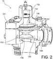
- the figure 2 shows an example of a control valve 15.
- the control valve 15 comprises a valve body 151 defining an air chamber 152 and a liquid chamber 153 separated from each other by a spool 154 comprising a seat 155 arranged in the liquid chamber 153.
- the regulating valve 15 can also comprise a membrane 156 secured on the one hand to the valve body 151 on its peripheral part 157, and on the other hand to the slide valve 154 on its central part.
- the air chamber 152 communicates for example with a pneumatic circuit (not shown) designed to control an air pressure in the air chamber 152.
- the pneumatic circuit comprises for example an air supply line via which the air chamber 152 is supplied with air so as to increase the air pressure in said air chamber 152, and an air exhaust duct through which air is exhausted from the air chamber 152 so as to decrease the air pressure in said air chamber 152.
- the supply and exhaust ducts may each be provided with a valve adapted to open and to close said supply or exhaust duct .
- the valves can be connected to the output interface of the control unit 31.
- the pneumatic circuit can further comprise a fourth pressure sensor 160 ( figure 1 ) designed to measure the air pressure in the air chamber 152.
- the fourth pressure sensor 160 can be connected to the input interface of the control unit 31.
- the liquid chamber 153 comprises an inlet 158 communicating with the outlet 17 of the pump 13, as well as an outlet orifice 159 communicating with the inlet 16 of the pump 13.
- the spool 154 is also able to move in the valve body 151, to bring the seat 155 of the said spool 154 closer to or further away from the outlet orifice 159 of the liquid chamber 153, depending on a difference between the pressure of air in the air chamber 152 and a pressure of the liquid circulating in the liquid chamber 153, from the inlet 158 to the outlet orifice 159.
- the control of the air pressure in the air chamber 152 of the regulating valve 15 makes it possible to vary the flow rate or the pressure of liquid passing through the regulating valve 15 and therefore the flow rate or the pressure of liquid circulating in the open discharge channel(s) 14a-14g .
- the air pressure in the air chamber 152 of the control valve 15 is low and the stresses applied by the control valve 15 to the liquid downstream of the pump 13 are reduced. This makes it possible to avoid any overpressure of the liquid circulating in the liquid circuit 12, downstream of the pump 13, which could lead to a water hammer and therefore to damage to the liquid circuit 12.
- the air pressure in the air chamber 152 of the control valve 15 can be safely increased again to regulate in flow or in pressure the discharge channel(s) 14a-14g thus opened. Changes in function of the spray system 10 thus take place without risk to the liquid circuit 12.
- the control unit 31 can determine the open outlet(s) 14a-14g to be closed directly from instructions to close one or more open outlet(s) 14a-14g or indirectly from the opening instructions of one or more discharge channels 14a-14g closed.
- Instructions for opening one or more closed discharge routes 14a-14g and, if necessary, for closing one or more open discharge routes 14a-14g can be sent by the farmer via the user interface.
- the control unit 31 may further be designed to decrease the air pressure in the air chamber 152 of the control valve 15 for a period predetermined target.
- a target period value can be stored in the data memory.
- the target period value can be prestored in the data memory and/or saved in the data memory by the farmer via the user interface.
- the target period value is assigned to the target period.
- the control unit 31 can in particular be designed to open the exhaust pipe of the pneumatic circuit, in particular by means of the valve of said exhaust pipe, during the target period, so as to evacuate air from the chamber 152 of the regulating valve 15 and to reduce the air pressure in said air chamber 152.
- control unit 31 is designed to decrease the air pressure in the air chamber 152 of the regulating valve 15 until said air pressure reaches a predetermined target pressure, in particular until until the air pressure measured by the fourth pressure sensor 160 reaches the target pressure.
- a target pressure value can be stored in the data memory.
- the target pressure value can be prestored in the data memory and/or saved in the data memory by the farmer via the user interface.
- the target pressure value is assigned to the target pressure.
- the control unit 31 can in particular be designed to open the exhaust line of the pneumatic circuit, in particular by means of the valve of said exhaust line, until the target pressure is reached.
- the picture 3 shows a method 100 for controlling the spraying system 10.
- the method 100 can be recorded in the program memory of the control unit 31.
- the method 100 comprises a step 101 of selective regulation, by means of the regulation valve 15, as a function of the discharge channel(s) 14a-14g open, of the flow rate of liquid circulating in the discharge channel(s) 14a-14g open. to the regulation flow, in particular when the or at least one of the open discharge channels 14a-14g is predetermined as being to be regulated in flow, or the pressure of liquid circulating in the discharge channel(s) 14a-14g open at the first regulation pressure, in particular when none of the open delivery channel(s) 14a-14g is predetermined as being to be regulated in flow.
- the method 100 comprises for example another step 102 of regulating, by means of the delivery valve 18b connecting the outlet 17 of the pump 13 to the said secondary delivery channel 14b, of the liquid pressure in the said secondary delivery channel 14b at the second regulation pressure.
- Step 101 of selective regulation and step 102 of pressure regulation in said secondary discharge path 14b are implemented at the same time.
- the method 100 comprises a step (not shown) of assigning to the second regulation pressure, the second regulation pressure value corresponding to the flow rate range in which the flow rate of liquid flowing in the discharge channel(s) 14a-14g open, in particular measured by the flowmeter 32, is included.
- the method 100 for example comprises a step (not shown) of assigning the regulation flow rate value corresponding to the said discharge channel(s) 14a-14g open, to the regulation flow rate.
- the method 100 comprises for example, prior to the step 101 of selective regulation, a step 103 of assigning the value of the first regulation pressure corresponding to the said outlet channel(s) 14a-14g open, at the first regulation pressure.
- the method 100 can also comprise a step 108 of receiving instructions to open one or more closed discharge channels 14a-14g and, if necessary, to close one or more open discharge channels 14a-14g, the closed delivery channel(s) 14a-14g to be opened and the open delivery channel(s) 14a-14g to be closed then being determined in the corresponding step 104 from of said instructions.
- Said instructions are for example sent by the farmer via the user interface.
- the open outlet or outlets 14a-14g to be closed can also be determined directly from instructions to close one or more open outlet or outlets 14a-14g or indirectly from the instructions to open one or several return routes 14a-14g closed.
- the air pressure in the air chamber 152 of the regulating valve 15 is for example reduced in the corresponding step 105 for a predetermined target period.
- the exhaust pipe of the pneumatic circuit can be opened during the target period, so as to evacuate air from the air chamber 152 of the regulating valve 15 and to reduce the air pressure in said air chamber 152.
- the air pressure in the air chamber 152 of the regulating valve 15 is reduced in the corresponding step 105 until said air pressure reaches a predetermined target pressure, in particular until the air pressure measured by the fourth pressure sensor 160 is equal to the target pressure.
- the pneumatic circuit exhaust line can be opened until the target pressure is reached.
Landscapes
- Life Sciences & Earth Sciences (AREA)
- Engineering & Computer Science (AREA)
- Insects & Arthropods (AREA)
- Pest Control & Pesticides (AREA)
- Wood Science & Technology (AREA)
- Zoology (AREA)
- Environmental Sciences (AREA)
- Catching Or Destruction (AREA)
Applications Claiming Priority (1)
| Application Number | Priority Date | Filing Date | Title |
|---|---|---|---|
| FR2012124A FR3116415B1 (fr) | 2020-11-25 | 2020-11-25 | Systeme de pulverisation pour engin agricole comprenant une vanne de regulation |
Publications (3)
| Publication Number | Publication Date |
|---|---|
| EP4005380A1 true EP4005380A1 (de) | 2022-06-01 |
| EP4005380C0 EP4005380C0 (de) | 2023-07-19 |
| EP4005380B1 EP4005380B1 (de) | 2023-07-19 |
Family
ID=74668990
Family Applications (1)
| Application Number | Title | Priority Date | Filing Date |
|---|---|---|---|
| EP21205286.4A Active EP4005380B1 (de) | 2020-11-25 | 2021-10-28 | Sprühsystem für landwirtschaftliche maschine, das ein einstellventil umfasst |
Country Status (5)
| Country | Link |
|---|---|
| EP (1) | EP4005380B1 (de) |
| AU (1) | AU2021261952A1 (de) |
| ES (1) | ES2953852T3 (de) |
| FR (1) | FR3116415B1 (de) |
| PL (1) | PL4005380T3 (de) |
Citations (4)
| Publication number | Priority date | Publication date | Assignee | Title |
|---|---|---|---|---|
| EP3269242A1 (de) * | 2016-07-13 | 2018-01-17 | Amazonen-Werke H. Dreyer GmbH & Co. KG | Pflanzenschutzspritze |
| EP2671447B1 (de) * | 2012-06-05 | 2018-08-01 | SA EXEL Industries | Landwirtschaftliche Feldspritze und Verfahren zur Steuerung einer landwirtschaftlichen Feldspritze |
| EP2671448B1 (de) * | 2012-06-05 | 2019-01-23 | SA EXEL Industries | Landwirtschaftliche Feldspritze und Verfahren zum Betrieb einer landwirtschaftlichen Feldspritze |
| DE202016008837U1 (de) * | 2016-07-13 | 2020-01-20 | Amazonen-Werke H. Dreyer Gmbh & Co. Kg | Pflanzenschutzspritze |
-
2020
- 2020-11-25 FR FR2012124A patent/FR3116415B1/fr active Active
-
2021
- 2021-10-28 ES ES21205286T patent/ES2953852T3/es active Active
- 2021-10-28 PL PL21205286.4T patent/PL4005380T3/pl unknown
- 2021-10-28 EP EP21205286.4A patent/EP4005380B1/de active Active
- 2021-11-05 AU AU2021261952A patent/AU2021261952A1/en active Pending
Patent Citations (4)
| Publication number | Priority date | Publication date | Assignee | Title |
|---|---|---|---|---|
| EP2671447B1 (de) * | 2012-06-05 | 2018-08-01 | SA EXEL Industries | Landwirtschaftliche Feldspritze und Verfahren zur Steuerung einer landwirtschaftlichen Feldspritze |
| EP2671448B1 (de) * | 2012-06-05 | 2019-01-23 | SA EXEL Industries | Landwirtschaftliche Feldspritze und Verfahren zum Betrieb einer landwirtschaftlichen Feldspritze |
| EP3269242A1 (de) * | 2016-07-13 | 2018-01-17 | Amazonen-Werke H. Dreyer GmbH & Co. KG | Pflanzenschutzspritze |
| DE202016008837U1 (de) * | 2016-07-13 | 2020-01-20 | Amazonen-Werke H. Dreyer Gmbh & Co. Kg | Pflanzenschutzspritze |
Also Published As
| Publication number | Publication date |
|---|---|
| FR3116415A1 (fr) | 2022-05-27 |
| ES2953852T3 (es) | 2023-11-16 |
| EP4005380C0 (de) | 2023-07-19 |
| AU2021261952A1 (en) | 2022-06-09 |
| PL4005380T3 (pl) | 2023-12-27 |
| EP4005380B1 (de) | 2023-07-19 |
| FR3116415B1 (fr) | 2023-01-06 |
Similar Documents
| Publication | Publication Date | Title |
|---|---|---|
| EP2611289B1 (de) | Sprühanordnung und zerstäuber mit mindestens einer derartigen anordnung | |
| EP3878277B1 (de) | Sprühsystem für landwirtschaftliche maschine und sprühverfahren mithilfe dieses systems | |
| FR2479870A1 (fr) | Dispositif et procede pour separer un gaz d'une suspension de fibres | |
| FR2519162A1 (fr) | Procede et dispositif d'etalonnage pour un appareil de pulverisation de fluide avec regulation de debit | |
| FR2507351A1 (fr) | Dispositif de dosage pour l'addition d'un fluide a un liquide s'ecoulant dans une conduite | |
| FR2813540A1 (fr) | Dispositif de pulverisation, notamment a usage agricole | |
| EP2425714B1 (de) | Vorrichtung und Verfahren zum Verteilen eines flüssigen Produkts zum Spritzen auf eine Fläche | |
| EP4118965B1 (de) | Flüssigkeitskreislauf für landwirtschaftliches sprühgerät mit dichtem transfersystem und dosiermechanismus | |
| EP4005380B1 (de) | Sprühsystem für landwirtschaftliche maschine, das ein einstellventil umfasst | |
| FR3060257B1 (fr) | Dispositif de distribution d'un produit sur une surface, comprenant un regulateur de pression pour egaliser les valeurs de pression de buses disposees le long d'un element de rampe de distribution | |
| FR3003187A1 (fr) | Dispositif de pulverisation pour engin notamment agricole | |
| FR3124351A1 (fr) | Système de régulation de pression et débit d’un pulvérisateur à pulvérisation localisée | |
| EP4056034B1 (de) | Spritzsystem für eine landwirtschaftliche maschine mit einem ersten und einem zweiten haupttank | |
| FR2516348A1 (fr) | Circuit de distribution d'un liquide pour un appareil de pulverisation a usage agricole avec conduite pour fluide de nettoyage des buses | |
| US20100107904A1 (en) | system and method for fluid flow control | |
| EP3945808B1 (de) | Rückgewinnungssystem für landwirtschaftliche spritze, entsprechende landwirtschaftliche spritze | |
| EP4304351B1 (de) | Sprühsystem für eine landwirtschaftliche maschine mit einem ersten und einem zweiten haupttank | |
| EP0927826A1 (de) | Pumpsystem für Flüssigkeiten | |
| FR2813755A1 (fr) | Procede de commande de la configuration en mode "incorporation" d'un circuit d'eau d'un pulverisateur agricole et pulverisateur agricole utilisant un tel procede | |
| EP4284686A1 (de) | Verfahren zur reinigung von kraftfahrzeugoberflächen | |
| FR2850884A1 (fr) | Dispositif de pulverisation a circulation continue | |
| JP2002001180A (ja) | 液体散布装置 | |
| FR3040004A1 (fr) | Dispositif d'agitation, centrale comprenant un tel dispositif et procede de controle de l'etancheite d'un tel dispositif | |
| RU2015701C1 (ru) | Гидровакуумная смесительная система жидких компонентов | |
| EP2705751B1 (de) | Automatisches Verfahren zur Bestimmung eines Modellerstellungsparameters eines Streuungssystems, Streuerverfahren und Streuungssystem, die einen solchen Parameter verwenden |
Legal Events
| Date | Code | Title | Description |
|---|---|---|---|
| PUAI | Public reference made under article 153(3) epc to a published international application that has entered the european phase |
Free format text: ORIGINAL CODE: 0009012 |
|
| STAA | Information on the status of an ep patent application or granted ep patent |
Free format text: STATUS: THE APPLICATION HAS BEEN PUBLISHED |
|
| AK | Designated contracting states |
Kind code of ref document: A1 Designated state(s): AL AT BE BG CH CY CZ DE DK EE ES FI FR GB GR HR HU IE IS IT LI LT LU LV MC MK MT NL NO PL PT RO RS SE SI SK SM TR |
|
| STAA | Information on the status of an ep patent application or granted ep patent |
Free format text: STATUS: REQUEST FOR EXAMINATION WAS MADE |
|
| 17P | Request for examination filed |
Effective date: 20221122 |
|
| RBV | Designated contracting states (corrected) |
Designated state(s): AL AT BE BG CH CY CZ DE DK EE ES FI FR GB GR HR HU IE IS IT LI LT LU LV MC MK MT NL NO PL PT RO RS SE SI SK SM TR |
|
| GRAP | Despatch of communication of intention to grant a patent |
Free format text: ORIGINAL CODE: EPIDOSNIGR1 |
|
| STAA | Information on the status of an ep patent application or granted ep patent |
Free format text: STATUS: GRANT OF PATENT IS INTENDED |
|
| INTG | Intention to grant announced |
Effective date: 20230321 |
|
| GRAS | Grant fee paid |
Free format text: ORIGINAL CODE: EPIDOSNIGR3 |
|
| GRAA | (expected) grant |
Free format text: ORIGINAL CODE: 0009210 |
|
| STAA | Information on the status of an ep patent application or granted ep patent |
Free format text: STATUS: THE PATENT HAS BEEN GRANTED |
|
| AK | Designated contracting states |
Kind code of ref document: B1 Designated state(s): AL AT BE BG CH CY CZ DE DK EE ES FI FR GB GR HR HU IE IS IT LI LT LU LV MC MK MT NL NO PL PT RO RS SE SI SK SM TR |
|
| REG | Reference to a national code |
Ref country code: GB Ref legal event code: FG4D Free format text: NOT ENGLISH |
|
| REG | Reference to a national code |
Ref country code: CH Ref legal event code: EP |
|
| REG | Reference to a national code |
Ref country code: DE Ref legal event code: R096 Ref document number: 602021003596 Country of ref document: DE |
|
| REG | Reference to a national code |
Ref country code: IE Ref legal event code: FG4D Free format text: LANGUAGE OF EP DOCUMENT: FRENCH |
|
| U01 | Request for unitary effect filed |
Effective date: 20230808 |
|
| U07 | Unitary effect registered |
Designated state(s): AT BE BG DE DK EE FI FR IT LT LU LV MT NL PT SE SI Effective date: 20230811 |
|
| U20 | Renewal fee for the european patent with unitary effect paid |
Year of fee payment: 3 Effective date: 20230926 |
|
| REG | Reference to a national code |
Ref country code: LT Ref legal event code: MG9D |
|
| REG | Reference to a national code |
Ref country code: ES Ref legal event code: FG2A Ref document number: 2953852 Country of ref document: ES Kind code of ref document: T3 Effective date: 20231116 |
|
| PG25 | Lapsed in a contracting state [announced via postgrant information from national office to epo] |
Ref country code: GR Free format text: LAPSE BECAUSE OF FAILURE TO SUBMIT A TRANSLATION OF THE DESCRIPTION OR TO PAY THE FEE WITHIN THE PRESCRIBED TIME-LIMIT Effective date: 20231020 |
|
| PG25 | Lapsed in a contracting state [announced via postgrant information from national office to epo] |
Ref country code: IS Free format text: LAPSE BECAUSE OF FAILURE TO SUBMIT A TRANSLATION OF THE DESCRIPTION OR TO PAY THE FEE WITHIN THE PRESCRIBED TIME-LIMIT Effective date: 20231119 |
|
| PG25 | Lapsed in a contracting state [announced via postgrant information from national office to epo] |
Ref country code: RS Free format text: LAPSE BECAUSE OF FAILURE TO SUBMIT A TRANSLATION OF THE DESCRIPTION OR TO PAY THE FEE WITHIN THE PRESCRIBED TIME-LIMIT Effective date: 20230719 Ref country code: NO Free format text: LAPSE BECAUSE OF FAILURE TO SUBMIT A TRANSLATION OF THE DESCRIPTION OR TO PAY THE FEE WITHIN THE PRESCRIBED TIME-LIMIT Effective date: 20231019 Ref country code: IS Free format text: LAPSE BECAUSE OF FAILURE TO SUBMIT A TRANSLATION OF THE DESCRIPTION OR TO PAY THE FEE WITHIN THE PRESCRIBED TIME-LIMIT Effective date: 20231119 Ref country code: HR Free format text: LAPSE BECAUSE OF FAILURE TO SUBMIT A TRANSLATION OF THE DESCRIPTION OR TO PAY THE FEE WITHIN THE PRESCRIBED TIME-LIMIT Effective date: 20230719 Ref country code: GR Free format text: LAPSE BECAUSE OF FAILURE TO SUBMIT A TRANSLATION OF THE DESCRIPTION OR TO PAY THE FEE WITHIN THE PRESCRIBED TIME-LIMIT Effective date: 20231020 |
|
| REG | Reference to a national code |
Ref country code: DE Ref legal event code: R097 Ref document number: 602021003596 Country of ref document: DE |
|
| PG25 | Lapsed in a contracting state [announced via postgrant information from national office to epo] |
Ref country code: SM Free format text: LAPSE BECAUSE OF FAILURE TO SUBMIT A TRANSLATION OF THE DESCRIPTION OR TO PAY THE FEE WITHIN THE PRESCRIBED TIME-LIMIT Effective date: 20230719 Ref country code: RO Free format text: LAPSE BECAUSE OF FAILURE TO SUBMIT A TRANSLATION OF THE DESCRIPTION OR TO PAY THE FEE WITHIN THE PRESCRIBED TIME-LIMIT Effective date: 20230719 Ref country code: SK Free format text: LAPSE BECAUSE OF FAILURE TO SUBMIT A TRANSLATION OF THE DESCRIPTION OR TO PAY THE FEE WITHIN THE PRESCRIBED TIME-LIMIT Effective date: 20230719 |
|
| PLBE | No opposition filed within time limit |
Free format text: ORIGINAL CODE: 0009261 |
|
| STAA | Information on the status of an ep patent application or granted ep patent |
Free format text: STATUS: NO OPPOSITION FILED WITHIN TIME LIMIT |
|
| PG25 | Lapsed in a contracting state [announced via postgrant information from national office to epo] |
Ref country code: MC Free format text: LAPSE BECAUSE OF FAILURE TO SUBMIT A TRANSLATION OF THE DESCRIPTION OR TO PAY THE FEE WITHIN THE PRESCRIBED TIME-LIMIT Effective date: 20230719 |
|
| 26N | No opposition filed |
Effective date: 20240422 |
|
| PG25 | Lapsed in a contracting state [announced via postgrant information from national office to epo] |
Ref country code: IE Free format text: LAPSE BECAUSE OF NON-PAYMENT OF DUE FEES Effective date: 20231028 |
|
| PG25 | Lapsed in a contracting state [announced via postgrant information from national office to epo] |
Ref country code: IE Free format text: LAPSE BECAUSE OF NON-PAYMENT OF DUE FEES Effective date: 20231028 |
|
| U20 | Renewal fee for the european patent with unitary effect paid |
Year of fee payment: 4 Effective date: 20240927 |
|
| REG | Reference to a national code |
Ref country code: CH Ref legal event code: PL |
|
| PG25 | Lapsed in a contracting state [announced via postgrant information from national office to epo] |
Ref country code: CH Free format text: LAPSE BECAUSE OF NON-PAYMENT OF DUE FEES Effective date: 20241031 |
|
| PG25 | Lapsed in a contracting state [announced via postgrant information from national office to epo] |
Ref country code: CY Free format text: LAPSE BECAUSE OF FAILURE TO SUBMIT A TRANSLATION OF THE DESCRIPTION OR TO PAY THE FEE WITHIN THE PRESCRIBED TIME-LIMIT; INVALID AB INITIO Effective date: 20211028 |
|
| U1N | Appointed representative for the unitary patent procedure changed after the registration of the unitary effect |
Representative=s name: BANDPAY & GREUTER; FR |
|
| PGFP | Annual fee paid to national office [announced via postgrant information from national office to epo] |
Ref country code: PL Payment date: 20250918 Year of fee payment: 5 |
|
| U20 | Renewal fee for the european patent with unitary effect paid |
Year of fee payment: 5 Effective date: 20250926 |
|
| PG25 | Lapsed in a contracting state [announced via postgrant information from national office to epo] |
Ref country code: TR Free format text: LAPSE BECAUSE OF FAILURE TO SUBMIT A TRANSLATION OF THE DESCRIPTION OR TO PAY THE FEE WITHIN THE PRESCRIBED TIME-LIMIT Effective date: 20230719 |
|
| PGFP | Annual fee paid to national office [announced via postgrant information from national office to epo] |
Ref country code: GB Payment date: 20251023 Year of fee payment: 5 |
|
| PGFP | Annual fee paid to national office [announced via postgrant information from national office to epo] |
Ref country code: CZ Payment date: 20251027 Year of fee payment: 5 |
|
| PGFP | Annual fee paid to national office [announced via postgrant information from national office to epo] |
Ref country code: ES Payment date: 20251110 Year of fee payment: 5 |
|
| PG25 | Lapsed in a contracting state [announced via postgrant information from national office to epo] |
Ref country code: HU Free format text: LAPSE BECAUSE OF FAILURE TO SUBMIT A TRANSLATION OF THE DESCRIPTION OR TO PAY THE FEE WITHIN THE PRESCRIBED TIME-LIMIT; INVALID AB INITIO Effective date: 20211028 |