EP4005418A1 - Atomiseur électronique, procédé d'assemblage d'atomiseur électronique et cigarette électronique - Google Patents
Atomiseur électronique, procédé d'assemblage d'atomiseur électronique et cigarette électronique Download PDFInfo
- Publication number
- EP4005418A1 EP4005418A1 EP20844097.4A EP20844097A EP4005418A1 EP 4005418 A1 EP4005418 A1 EP 4005418A1 EP 20844097 A EP20844097 A EP 20844097A EP 4005418 A1 EP4005418 A1 EP 4005418A1
- Authority
- EP
- European Patent Office
- Prior art keywords
- sealing portion
- closure
- sealing
- atomizing core
- flow passage
- Prior art date
- Legal status (The legal status is an assumption and is not a legal conclusion. Google has not performed a legal analysis and makes no representation as to the accuracy of the status listed.)
- Withdrawn
Links
- 239000003571 electronic cigarette Substances 0.000 title claims description 19
- 238000000034 method Methods 0.000 title claims description 10
- 238000007789 sealing Methods 0.000 claims abstract description 145
- 239000007788 liquid Substances 0.000 claims abstract description 49
- 230000004308 accommodation Effects 0.000 claims abstract description 31
- 230000000149 penetrating effect Effects 0.000 claims abstract description 14
- 239000000919 ceramic Substances 0.000 claims description 66
- 239000011159 matrix material Substances 0.000 claims description 42
- 238000010438 heat treatment Methods 0.000 claims description 32
- 235000019504 cigarettes Nutrition 0.000 claims description 11
- WABPQHHGFIMREM-UHFFFAOYSA-N lead(0) Chemical group [Pb] WABPQHHGFIMREM-UHFFFAOYSA-N 0.000 claims description 4
- 239000000796 flavoring agent Substances 0.000 claims description 3
- 235000019634 flavors Nutrition 0.000 claims description 3
- 239000012466 permeate Substances 0.000 claims 1
- MCMNRKCIXSYSNV-UHFFFAOYSA-N Zirconium dioxide Chemical compound O=[Zr]=O MCMNRKCIXSYSNV-UHFFFAOYSA-N 0.000 description 16
- 238000001746 injection moulding Methods 0.000 description 9
- 229910010293 ceramic material Inorganic materials 0.000 description 6
- VYPSYNLAJGMNEJ-UHFFFAOYSA-N Silicium dioxide Chemical compound O=[Si]=O VYPSYNLAJGMNEJ-UHFFFAOYSA-N 0.000 description 5
- 238000004519 manufacturing process Methods 0.000 description 5
- 239000000741 silica gel Substances 0.000 description 5
- 229910002027 silica gel Inorganic materials 0.000 description 5
- 238000002347 injection Methods 0.000 description 4
- 239000007924 injection Substances 0.000 description 4
- 239000000463 material Substances 0.000 description 3
- 230000013011 mating Effects 0.000 description 2
- 238000000465 moulding Methods 0.000 description 2
- 239000011148 porous material Substances 0.000 description 2
- 239000000243 solution Substances 0.000 description 2
- 238000004381 surface treatment Methods 0.000 description 2
- 230000004075 alteration Effects 0.000 description 1
- 238000000889 atomisation Methods 0.000 description 1
- 230000007797 corrosion Effects 0.000 description 1
- 238000005260 corrosion Methods 0.000 description 1
- 230000007547 defect Effects 0.000 description 1
- 238000005516 engineering process Methods 0.000 description 1
- 238000001125 extrusion Methods 0.000 description 1
- 230000006872 improvement Effects 0.000 description 1
- 230000004048 modification Effects 0.000 description 1
- 238000012986 modification Methods 0.000 description 1
- 230000002093 peripheral effect Effects 0.000 description 1
- 229920001296 polysiloxane Polymers 0.000 description 1
- 230000008569 process Effects 0.000 description 1
- 230000003014 reinforcing effect Effects 0.000 description 1
- 239000000779 smoke Substances 0.000 description 1
Images


Classifications
-
- A—HUMAN NECESSITIES
- A24—TOBACCO; CIGARS; CIGARETTES; SIMULATED SMOKING DEVICES; SMOKERS' REQUISITES
- A24F—SMOKERS' REQUISITES; MATCH BOXES; SIMULATED SMOKING DEVICES
- A24F40/00—Electrically operated smoking devices; Component parts thereof; Manufacture thereof; Maintenance or testing thereof; Charging means specially adapted therefor
- A24F40/40—Constructional details, e.g. connection of cartridges and battery parts
- A24F40/42—Cartridges or containers for inhalable precursors
-
- A—HUMAN NECESSITIES
- A24—TOBACCO; CIGARS; CIGARETTES; SIMULATED SMOKING DEVICES; SMOKERS' REQUISITES
- A24F—SMOKERS' REQUISITES; MATCH BOXES; SIMULATED SMOKING DEVICES
- A24F40/00—Electrically operated smoking devices; Component parts thereof; Manufacture thereof; Maintenance or testing thereof; Charging means specially adapted therefor
- A24F40/40—Constructional details, e.g. connection of cartridges and battery parts
- A24F40/46—Shape or structure of electric heating means
-
- A—HUMAN NECESSITIES
- A24—TOBACCO; CIGARS; CIGARETTES; SIMULATED SMOKING DEVICES; SMOKERS' REQUISITES
- A24F—SMOKERS' REQUISITES; MATCH BOXES; SIMULATED SMOKING DEVICES
- A24F40/00—Electrically operated smoking devices; Component parts thereof; Manufacture thereof; Maintenance or testing thereof; Charging means specially adapted therefor
- A24F40/10—Devices using liquid inhalable precursors
Definitions
- the present disclosure relates to the field of electronic cigarettes, and in particular, to an electronic atomizer, an electronic atomizer assembly method, and an electronic cigarette.
- Patent Application No. 201811033876.0 of the People's Republic of China discloses an atomizer and an electronic cigarette, including an atomizing core, a first plastic member assembling the atomizing core, a second plastic member, a housing sleeving an exterior of the first plastic member, and a cover body snapped with the housing and covering an exterior of the second plastic member.
- a first sealing portion is clamped between the atomizing core and the first plastic member, and a second sealing portion is clamped between a periphery of the first plastic member and the housing.
- the first plastic member is further provided with an air hole.
- the housing is provided with an air passage communicated with the air hole. The air hole is connected to the air passage, and a third sealing member is clamped between the two.
- the first, second, and third sealing members are provided to prevent e-liquid from leaking from the housing.
- the three sealing members are provided independently and need to be assembled between corresponding parts and components.
- the sealing members are made of silica gel materials, which are soft and difficult to achieve automatic production, and need to be manually assembled. As a result, manufacturing efficiency is low, and it is difficult to guarantee the quality.
- an electronic atomizer including: a cartridge tube provided with an e-liquid storage cavity and a flue, a closure member closing the e-liquid storage cavity, a sealing member, an atomizing core provided in the closure member, and a base; the closure member including a closure end, an accommodation end extending downward from the closure end, a flow passage vertically penetrating through the closure member, and an air passage separated from the flow passage, wherein the sealing member is integrally formed on the closure member, and the sealing member includes: a first sealing portion covering an outer side of the atomizing core, a second sealing portion covering an outer periphery of the closure end and abutting against an inner wall surface of the cartridge tube, and a third sealing portion fitted to a top end of the air passage and abutting against an end edge of the flue; and the e-liquid storage cavity is communicated with an upper end surface of the atomizing core through the flow passage.
- an assembly method of an electronic atomizer including the following steps:
- an electronic cigarette including a cigarette pole and an electronic atomizer inserted to the cigarette pole;
- the electronic atomizer including: a cartridge tube provided with an e-liquid storage cavity and a flue, a closure member closing the e-liquid storage cavity, a sealing member, an atomizing core provided in the closure member, and a base;
- the closure member including a closure end, an accommodation end extending downward from the closure end, a flow passage vertically penetrating through the closure member, and an air passage separated from the flow passage; wherein a bottom surface of the atomizing core is provided with a heating element, and the base is provided with electrodes electrically connected to the heating element; at least four of the electrodes are electrically connected to contact points of the heating element, and a circuit of the cigarette pole is electrically connected to at least two of the electrodes to enable the electronic atomizer to be applicable to different cigarette poles to achieve different flavors.
- an atomizing device including: an atomizing core and a closure member, wherein the atomizing core is integrally formed in the closure member, the atomizing core includes a ceramic matrix and a ceramic core located inside the ceramic matrix, the ceramic matrix is made of zirconia ceramic, the ceramic core is made of porous ceramic, the ceramic matrix includes a frame body and a core cavity vertically penetrating through the frame body, the porous ceramic is located in the core cavity, the closure member includes an outer wall, and an outer surface of the ceramic matrix and an inner side surface of the outer wall are integrally formed and form a joint surface.
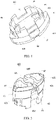
- the atomizing device of the present disclosure includes a cartridge tube 10 provided with a flue 13 and an e-liquid storage cavity 12, a closure member 40 mounted in the cartridge tube 10 and closing the e-liquid storage cavity 12, a sealing member 60 formed in the closure member 40, an atomizing core 30 provided at a lower end of the closure member 40, a base 50 snapped with the closure member 40 to clamp the atomizing core 30, and a cover body 20 sleeving a periphery of the base 50 and snapped with the cartridge tube 10.
- the base 50 and the cover body 20 may be designed into an integrated structure, that is, the base 50 is directly snapped with the cartridge tube 10.
- the cartridge tube 10 includes a tube body 11, a mating end 14 located at a top of the tube body 11, a first snapping portion 141 disposed at two sides of the mating end 14, an e-liquid storage cavity 12 located in the tube body 11, and a flue 13 penetrating through a bottom of the tube body 11.
- a top end of the flue 13 is provided with a connection portion 131.
- An outer diameter of the connection portion 131 is smaller than an outer diameter of the flue 13.
- the flue 13 is located at the middle of the e-liquid storage cavity 12.
- the flue may also be disposed at one side or two sides of the e-liquid storage cavity 12.
- the closure member 40 includes a closure end 41 and an accommodation end 42 extending downward from the closure end 41.
- a top outer edge of the closure end 41 is provided with a closure groove 412.
- the accommodation end 42 is provided with an accommodation cavity 44 toward a direction of the atomizing core 30.
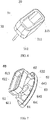
- the closure member 40 further includes: a flow passage 43 vertically penetrating through the closure end 41 and communicated to the accommodation cavity 44, and an air passage 45 independent of the flow passage and not communicated to the accommodation cavity 44.
- the air passage 45 includes: a connection air passage 453 vertically penetrating through the closure end 41, a traverse air passage 451 non-vertically penetrating through the closure end 41, and an outer-side air passage 452 extending downward at an outer wall of the accommodation end 42 from the traverse air passage 451.
- a traverse outer side of the accommodation end 42 is provided with a second snapping portion 421.
- the connection air passage 453 of the closure member 40 extends outward to form a first groove 48 at a position different from the flow passage 43.
- An outer side of the flow passage 43 of the closure member 40 extends to form a second groove 47.
- the sealing member 60 is integrally formed on the closure member 40.
- the sealing member 60 includes a first sealing portion 61 formed in the accommodation cavity 44, a second sealing portion 63 formed on an outer periphery of the closure groove 412 at a top outer edge of the closure end 41, and a third sealing portion 64 formed at an inner wall of the connection air passage 453 of the closure member 40.
- the first sealing portion 61 includes a first fitting portion 611 formed around an inner wall of the accommodation cavity 44, an opening 613 vertically penetrating through the first sealing portion 61, and a second fitting portion 612 formed at an outer periphery of the opening 416 and fitted to a bottom wall of the accommodation cavity 44.
- a plane where the first sealing portion 611 is located is perpendicular with a plane where the second fitting portion 612 is located.
- the second sealing portion 63 includes a third fitting portion 631 fitted to the outer periphery of the closure groove 412 and a fourth fitting portion 632 covering an outer periphery of an end edge of the closure end 41.
- the third sealing portion 64 includes: a fifth fitting portion 641 fitted to an inner wall surface of the connection air passage 453, and a through hole 642 formed at the middle of the third sealing portion 64.
- a first connecting portion 62 is connected between the first sealing portion 61 and the second sealing portion 63.
- the first connecting portion 62 extends upward from an outer side wall of the flow passage 43 to the second groove 47 formed at a top outer side of the flow passage 43 to be connected to the fourth fitting portion 632.
- a second connecting portion 643 is connected between the second sealing portion 63 and the third sealing portion 64. The second connecting portion 643 extends along the first groove 48 and is connected to outer side walls of the fourth fitting portion 632 and the fifth fitting portion 641.
- first, second, and third sealing portions 61, 63, and 64 may also be provided independently, without being connected through the first and second connecting portions 62 and 643.
- the sealing member 60 when the sealing member 60 is injection-molded, three injection points need to be provided respectively corresponding to the first, second, and third sealing portions 61, 63, and 64.
- the configuration of a mold for injection molding is relatively complicated. With the first and second connecting portions 62 and 643 being the flow passage of silica gel liquid, only one injection point needs to be provided.
- first connecting portion 62 may be omitted, only the second connecting portion 643 is remained, the second sealing portion 63 and the third sealing portion 64 are located in a same plane, and the provision of one injection point will not affect a flow rate of the silica gel liquid and will not lead to an unsaturated mold.
- the closure member 40 is injection-molded, and upon completion of the injection molding of the injection-molded part 40, part of the mold for the injection molding may be shared when subsequently injection molding of the sealing member 60. In this case, it only needs to remove mold parts filling a reserved region from a part needing silicone molding, and then the silica gel liquid can be injected to form the sealing member 60.
- the atomizing core 30 is made of porous ceramic, and includes a ceramic matrix 31, a heating element 32 affixed to a bottom of the ceramic matrix 31, and a lead wire 33 connected to the heating element 32.
- the ceramic matrix 31 includes a head 311 and a tail 312 extending from the head 311.
- the head 311 is installed into the first sealing portion 61 of the sealing member 60, and an outer edge of the head 311 mates with an inner wall of the accommodation cavity 44 to clamp the first fitting portion 611 of the first sealing portion 61.
- a top end of the head 311 is further provided with an e-liquid storage tank 313.
- a peripheral top surface of the e-liquid storage tank 313 is fitted to the second fitting portion 612.
- the e-liquid storage tank 313 is communicated to the e-liquid storage cavity 12 of the cartridge tube 10 through the flow passage 43 and the opening 613.
- E-liquid in the e-liquid storage cavity 12 flows into the e-liquid storage tank 313 through the flow passage 43 and the opening 613.
- the e-liquid in the e-liquid storage tank 313 seeps out, by capillarity, through a capillary hole in the ceramic matrix 31 to a surface where the heating element 32 is located for atomization.
- a traverse width of the tail 32 is smaller than a traverse width of the head 31.
- the heating element 32 extends from a bottom surface and two side surfaces of the tail 32, and four lead wires 33 are respectively led out from the bottom surface and the two side surfaces.
- the base 50 includes a body portion 51, a clamping portion 54 extending from two sides of the body portion 51 toward the closure member 40, and a plurality of electrodes 56 formed in the body portion 51.
- the body portion 51 vertically penetrates to form an air inlet hole 531 communicated with the outer-side air passage and a plurality of terminal holes 532 accommodating the electrodes 56.
- the electrodes 56 pass through the terminal holes 532 and are exposed to an end face of the body portion 51.
- the lead wires 33 are respectively electrically connected to the electrodes 56.
- the clamping portion 54 is provided with a third snapping portion 55 snapped with the second snapping portion 421 of the closure member 40.
- the middle of the end face of the body portion 51 protrudes upward to form a protruding portion 53 and a recessed escape groove 52 located at an outer edge of the protruding portion 53.
- the terminal holes 532 and the air inlet hole 531 are formed in the protruding portion 53.
- an elastic contact portion is provided at an end of the electrode 56 facing the atomizing core 30, and the elastic contact portion directly abuts against the heating element 32 at a bottom surface of the atomizing core 30. In this case, the lead wire 33 is no longer needed.
- Four electrodes 56 are provided to select different control programs and flavors corresponding to different cigarette poles.
- the cover body 20 includes a cylindrical body 21, a fourth snapping portion 23 disposed at two sides of the cylindrical body 21 and snapped with the first snapping portion 141, an escape port 22 formed at an end face of the cylindrical body 21, and an edge covering portion 24.
- the protruding portion 53 is exposed from the escape port 22, and the edge covering portion 24 covers the escape groove 52, so that a surface of the protruding portion 53 is flush with a surface of the edge covering portion 24.
- a process of manufacturing the atomizing device of the present disclosure is as follows: In the presence of the lead wires 33: first, the sealing member 60 is integrally formed on the closure member 40; then, the lead wires 33 are inserted into the electrodes 56 for electrical connection; the atomizing core 30 is mounted into the first sealing portion 61 of the sealing member 60; then the base 50 is snapped with the closure member 40 to clamp the atomizing core 30; then e-liquid is injected into the e-liquid storage cavity 12 of the cartridge tube 10, and the closure member 40, the base 50, and the atomizing core 30 therein are inserted into the cartridge tube 10; at this time, the second sealing portion 63 of the sealing member 60 is clamped between the closure member 40 and an inner wall surface of the cartridge tube 10 to prevent seepage; the third sealing portion 64 of the sealing member 60 is clamped between an outer wall surface of an end portion of the flue 13 and an inner wall surface of the connection air passage 453 to prevent seepage; finally, the cover body 20 covers the base 50, and the fourth snapping
- the atomizing core 30 is first combined with the sealing member 60 in the closure member 40, and then the base 50 is snapped with the closure member 40.
- the sealing member 60 is integrally formed on the closure member 40, to avoid the defect that separated silica gel needs to be manually assembled and cannot be automatically assembled.
- the sealing member 60 includes first, second, and third sealing portions 61, 63, and 64 to respectively achieve sealing of the outer periphery of the atomizing core 30, between the closure member 60 and the cartridge tube 10, and between the flue 13 and the e-liquid storage cavity 12p; moreover, the three sealing portions are integrally provided, and are injection-molded in one time in the closure member during injection molding. When molding the sealing member 60, only one injection point needs to be provided, thereby reducing injection molding costs.
- a power supply is connected to the atomizing device, so that a current is conducted to the heating element 33 through the electrodes 56 to heat the heating element 33 and atomize e-liquid attached to a bottom surface of the atomizing core 30 to produce smoke.
- the electronic cigarette of the present disclosure is formed by inserting the atomizing device into an electronic cigarette pole.
- the electronic cigarette pole is integrated with a controller, a control circuit, a power supply, and so on.
- an atomizing core according to Embodiment 2 includes a ceramic matrix 80 and a ceramic core 90 located inside the ceramic matrix 80.
- the ceramic matrix 80 is made of zirconia ceramic, namely a dense ceramic material, and will not seep.
- the ceramic core 90 is made of made of porous ceramic, that is, there is a pore structure inside the ceramic core 90, and capillarity will be generated.
- the ceramic matrix 80 includes a frame body 81 and a core cavity 82 vertically penetrating through the frame body 81. During manufacturing, the ceramic matrix 80 is first formed, then the core cavity 82 is filled with a porous ceramic material, and finally the porous ceramic material is sintered to form the ceramic core 90.
- the atomizing device includes the atomizing core and a closure member 70.
- An outer side surface of the ceramic matrix 80 of the atomizing core is integrally formed on the closure member 70 to prevent liquid leakage, and there is no need to provide a sealing member.
- the closure member 70 is made of a plastic material and includes an outer wall 71 and a cavity 72 enclosed by the outer wall 71. An upper surface of the ceramic core 90 is exposed within the cavity 72.
- An outer side surface of an outer frame body of the ceramic matrix 80 and an inner side surface of the outer wall 71 are integrally injection-molded.
- the treatment on the outer surface of the zirconia ceramic may be obtained with reference to Patent Application No. 201710109397.1 of the People's Republic of China. Certainly, the treatment on the outer surface of the zirconia ceramic will not be limited to the content disclosed in the Patent Application No. 201710109397.1 , and other existing technology for surface treatment on the zirconia ceramic surface may also be adopted.
- a manufacturing method of the atomizing device according to Embodiment 2 is as follows.
- a ceramic matrix 80 with a core cavity 82 is provided, and the core cavity 82 is filled with a porous ceramic material.
- the ceramic matrix 80 is zirconia ceramic, with quite high hardness and density, and will not seep or crack.
- the porous ceramic material in the ceramic matrix 80 and the core cavity 82 is sintered to form a ceramic core 90 located in the core cavity 82.
- the obtained ceramic core 90 is provided with micropores, and the micropores will generate capillarity for e-liquid to pass through.
- an outer surface of the ceramic matrix 80 is corroded to form a plurality of nano holes at the outer surface of the ceramic matrix 80.
- This step is disclosed in previous patent technical documents, mainly to facilitate the subsequent injection molding process.
- the treated ceramic matrix 80 is nano injection-molded to form a closure member 70.
- a bonding surface of the ceramic matrix 80 and the closure member 70 is the surface treated by S30, that is, a plurality of nano-pore structures are formed, by corrosion, at the bonding surface of the ceramic matrix 80.
- the ceramic core 90 made of a porous ceramic material is directly sintered at the middle of the ceramic matrix 80, which solves the technical problem that the porous ceramic is not strong enough and thus is easy to be broken by extrusion.
- the ceramic matrix 80 is directly integrally formed with the closure member 70 by zirconia ceramic, and seepage can be prevented without any sealing member between the closure member 70 and the ceramic matrix 80. Also, removal of the sealing member makes it easier to automatically assemble the atomizing device of the present disclosure.
Landscapes
- Electrostatic Spraying Apparatus (AREA)
Applications Claiming Priority (6)
| Application Number | Priority Date | Filing Date | Title |
|---|---|---|---|
| CN201910440531 | 2019-05-24 | ||
| CN201910666798.6A CN110447960A (zh) | 2019-05-24 | 2019-07-23 | 封闭件及电子雾化器 |
| CN201910667601.0A CN110447961B (zh) | 2019-05-24 | 2019-07-23 | 雾化芯、雾化装置、雾化装置的制造方法及电子烟 |
| CN201910666763.2A CN110403248A (zh) | 2019-05-24 | 2019-07-23 | 电子烟 |
| CN201910666768.5A CN110477455A (zh) | 2019-05-24 | 2019-07-23 | 电子雾化器及组装方法 |
| PCT/CN2020/087466 WO2021012740A1 (fr) | 2019-05-24 | 2020-04-28 | Atomiseur électronique, procédé d'assemblage d'atomiseur électronique et cigarette électronique |
Publications (2)
| Publication Number | Publication Date |
|---|---|
| EP4005418A1 true EP4005418A1 (fr) | 2022-06-01 |
| EP4005418A4 EP4005418A4 (fr) | 2023-08-23 |
Family
ID=68483120
Family Applications (1)
| Application Number | Title | Priority Date | Filing Date |
|---|---|---|---|
| EP20844097.4A Withdrawn EP4005418A4 (fr) | 2019-05-24 | 2020-04-28 | Atomiseur électronique, procédé d'assemblage d'atomiseur électronique et cigarette électronique |
Country Status (4)
| Country | Link |
|---|---|
| US (1) | US12102126B2 (fr) |
| EP (1) | EP4005418A4 (fr) |
| CN (1) | CN110447960A (fr) |
| WO (1) | WO2021012740A1 (fr) |
Families Citing this family (5)
| Publication number | Priority date | Publication date | Assignee | Title |
|---|---|---|---|---|
| CN209546930U (zh) * | 2018-12-13 | 2019-10-29 | 常州市派腾电子技术服务有限公司 | 雾化头、雾化器及电子烟 |
| CN110447960A (zh) * | 2019-05-24 | 2019-11-15 | 东莞市阿尔法电子科技有限公司 | 封闭件及电子雾化器 |
| CN113017152B (zh) * | 2021-03-04 | 2025-03-21 | 深圳麦克韦尔科技有限公司 | 一种雾化器及其电子雾化装置 |
| CN114190602B (zh) * | 2021-11-11 | 2024-07-02 | 立讯精密工业股份有限公司 | 雾化芯及雾化器 |
| CN116919021A (zh) * | 2022-04-08 | 2023-10-24 | 比亚迪精密制造有限公司 | 雾化装置和具有其的电子烟 |
Family Cites Families (40)
| Publication number | Priority date | Publication date | Assignee | Title |
|---|---|---|---|---|
| US20100200008A1 (en) * | 2009-02-09 | 2010-08-12 | Eli Taieb | E-Cigarette With Vitamin Infusion |
| US20120118307A1 (en) * | 2010-11-12 | 2012-05-17 | Martin Tu | Inhalant smoke generator |
| CN203538370U (zh) * | 2013-08-23 | 2014-04-16 | 刘秋明 | 雾化组件及电子烟 |
| CN204120222U (zh) * | 2014-05-30 | 2015-01-28 | 深圳市麦克韦尔科技有限公司 | 电子烟及其雾化器和烟弹管 |
| CN204120224U (zh) | 2014-06-25 | 2015-01-28 | 惠州市吉瑞科技有限公司 | 一种电子烟盒 |
| CN104287096B (zh) * | 2014-10-20 | 2016-06-15 | 深圳麦克韦尔股份有限公司 | 电子烟及其雾化组件安装座 |
| WO2016090426A1 (fr) | 2014-12-08 | 2016-06-16 | Kinchington Holdings Pty Ltd | Cigarette électronique |
| CN107182139B (zh) | 2016-03-11 | 2020-06-09 | 周宏明 | 一种金属膜多孔陶瓷发热体及其应用 |
| CN107173849B (zh) | 2016-03-11 | 2019-11-22 | 周宏明 | 一种导电陶瓷膜多孔陶瓷发热体及其应用 |
| CN205757175U (zh) * | 2016-03-15 | 2016-12-07 | 惠州市吉瑞科技有限公司深圳分公司 | 一种电子烟雾化器及其发热体的成型装置 |
| CN206005949U (zh) * | 2016-08-03 | 2017-03-15 | 卓尔悦欧洲控股有限公司 | 一种电子烟 |
| CN206062138U (zh) * | 2016-09-14 | 2017-04-05 | 昂纳自动化技术(深圳)有限公司 | 雾化芯组件及电子烟雾化装置 |
| CN107010998B (zh) | 2017-02-27 | 2020-07-31 | 广东长盈精密技术有限公司 | 陶瓷的表面处理方法、陶瓷制品及陶瓷塑料复合体 |
| CN107006896B (zh) | 2017-05-05 | 2019-04-09 | 湖北中烟工业有限责任公司 | 一种复合的陶瓷雾化器及其制备方法 |
| CN207185916U (zh) * | 2017-08-25 | 2018-04-06 | 常州市派腾电子技术服务有限公司 | 雾化器及电子烟 |
| CN107650326A (zh) | 2017-09-11 | 2018-02-02 | 歌尔股份有限公司 | 基材和塑料的结合件及其制备方法 |
| CN109531913B (zh) | 2017-09-21 | 2021-02-26 | 谷崧精密工业股份有限公司 | 陶瓷塑料复合体及其制造方法 |
| CN207341185U (zh) | 2017-11-01 | 2018-05-11 | 陈永 | 雾化器及电子烟 |
| CN207784285U (zh) * | 2018-01-12 | 2018-08-31 | 深圳阿尔法科技智能有限公司 | 一种加热不燃烧气雾发生装置 |
| CN108308716B (zh) | 2018-02-13 | 2022-07-12 | 深圳麦克韦尔科技有限公司 | 电子烟及其发热组件 |
| CN108379702B (zh) | 2018-05-11 | 2019-10-15 | 泰安大陆医疗器械有限公司 | 医用雾化器 |
| CN208550032U (zh) | 2018-06-22 | 2019-03-01 | 常州市派腾电子技术服务有限公司 | 雾化器及电子烟 |
| CN109452691B (zh) * | 2018-11-29 | 2024-04-23 | 深圳麦克韦尔科技有限公司 | 雾化装置及电子雾化设备 |
| CN117461891A (zh) * | 2018-09-05 | 2024-01-30 | 深圳麦克韦尔科技有限公司 | 雾化装置及电子烟 |
| CN109393566A (zh) | 2018-09-28 | 2019-03-01 | 深圳市卓力能电子有限公司 | 一种电子烟发热体 |
| CN109527657A (zh) | 2018-12-21 | 2019-03-29 | 深圳市合元科技有限公司 | 雾化组件的制备方法及电子烟雾化器 |
| CN211323052U (zh) | 2019-05-24 | 2020-08-25 | 东莞市阿尔法电子科技有限公司 | 雾化芯、雾化装置及电子烟 |
| CN110403248A (zh) * | 2019-05-24 | 2019-11-05 | 东莞市阿尔法电子科技有限公司 | 电子烟 |
| CN110447961B (zh) * | 2019-05-24 | 2024-06-28 | 东莞市阿尔法电子科技有限公司 | 雾化芯、雾化装置、雾化装置的制造方法及电子烟 |
| CN211020987U (zh) * | 2019-05-24 | 2020-07-17 | 东莞市阿尔法电子科技有限公司 | 封闭件及电子雾化器 |
| CN110477455A (zh) * | 2019-05-24 | 2019-11-22 | 东莞市阿尔法电子科技有限公司 | 电子雾化器及组装方法 |
| CN110447960A (zh) * | 2019-05-24 | 2019-11-15 | 东莞市阿尔法电子科技有限公司 | 封闭件及电子雾化器 |
| CN211021000U (zh) | 2019-05-24 | 2020-07-17 | 东莞市阿尔法电子科技有限公司 | 电子烟 |
| US20220256925A1 (en) * | 2019-06-28 | 2022-08-18 | Shenzhen First Union Technology Co., Ltd. | Electronic cigarette atomiser and electronic cigarette |
| EP3973798B1 (fr) * | 2020-06-09 | 2025-07-30 | Shenzhen Huachengda Precision Industry Co., Ltd. | Dispositif d'atomisation de recyclage de liquide |
| CN213344343U (zh) * | 2020-06-10 | 2021-06-04 | 深圳市合元科技有限公司 | 电子烟雾化器及电子烟 |
| CN214903777U (zh) * | 2020-09-21 | 2021-11-30 | 东莞市阿尔法电子科技有限公司 | 发热组件及烟弹 |
| CN112545064B (zh) * | 2020-12-18 | 2025-06-06 | 深圳麦克韦尔科技有限公司 | 雾化器及电子雾化装置 |
| CN215303020U (zh) * | 2020-12-30 | 2021-12-28 | 江门摩尔科技有限公司 | 雾化器及电子雾化装置 |
| CN214710376U (zh) * | 2020-12-30 | 2021-11-16 | 江门摩尔科技有限公司 | 雾化器及电子雾化装置 |
-
2019
- 2019-07-23 CN CN201910666798.6A patent/CN110447960A/zh active Pending
-
2020
- 2020-04-28 WO PCT/CN2020/087466 patent/WO2021012740A1/fr not_active Ceased
- 2020-04-28 EP EP20844097.4A patent/EP4005418A4/fr not_active Withdrawn
-
2021
- 2021-06-29 US US17/362,281 patent/US12102126B2/en active Active
Also Published As
| Publication number | Publication date |
|---|---|
| WO2021012740A1 (fr) | 2021-01-28 |
| EP4005418A4 (fr) | 2023-08-23 |
| US20210321671A1 (en) | 2021-10-21 |
| CN110447960A (zh) | 2019-11-15 |
| US12102126B2 (en) | 2024-10-01 |
Similar Documents
| Publication | Publication Date | Title |
|---|---|---|
| US12102126B2 (en) | Electronic atomizer, electronic atomizer assembly method, and electronic cigarette | |
| CN110447961B (zh) | 雾化芯、雾化装置、雾化装置的制造方法及电子烟 | |
| CN211021000U (zh) | 电子烟 | |
| CN110477455A (zh) | 电子雾化器及组装方法 | |
| CN211323052U (zh) | 雾化芯、雾化装置及电子烟 | |
| CN214802289U (zh) | 雾化芯及烟弹 | |
| CN203662025U (zh) | 电子烟 | |
| US10512284B2 (en) | Atomizer of electronic cigarette | |
| EP3895562B1 (fr) | Tête d'atomisation, atomiseur et cigarette électronique | |
| CN113197360B (zh) | 强度高的雾化单元、组件和装置 | |
| WO2021062781A1 (fr) | Dispositif d'atomisation électronique et atomiseur associé | |
| CN110403248A (zh) | 电子烟 | |
| CN110338462B (zh) | 烟弹及组装方法 | |
| CN106983177A (zh) | 电子烟及其雾化装置 | |
| CN215873476U (zh) | 封闭体、雾化装置及电子烟 | |
| CN110338463B (zh) | 封闭体及烟弹 | |
| CN211020987U (zh) | 封闭件及电子雾化器 | |
| CN113115999A (zh) | 烟弹及电子烟 | |
| US12219993B2 (en) | Closure body and cartridge | |
| CN215224729U (zh) | 雾化装置及电子烟 | |
| CN206079021U (zh) | 陶瓷复合电子烟加热管及其电子烟雾化芯 | |
| CN216088881U (zh) | 烟弹及电子烟 | |
| CN113116000A (zh) | 封闭体、雾化装置及电子烟 | |
| CN113876039A (zh) | 发热核心组件、雾化装置及雾化设备 | |
| CN218515185U (zh) | 一种雾化组件及其雾化器 |
Legal Events
| Date | Code | Title | Description |
|---|---|---|---|
| STAA | Information on the status of an ep patent application or granted ep patent |
Free format text: STATUS: THE INTERNATIONAL PUBLICATION HAS BEEN MADE |
|
| PUAI | Public reference made under article 153(3) epc to a published international application that has entered the european phase |
Free format text: ORIGINAL CODE: 0009012 |
|
| STAA | Information on the status of an ep patent application or granted ep patent |
Free format text: STATUS: REQUEST FOR EXAMINATION WAS MADE |
|
| 17P | Request for examination filed |
Effective date: 20210630 |
|
| AK | Designated contracting states |
Kind code of ref document: A1 Designated state(s): AL AT BE BG CH CY CZ DE DK EE ES FI FR GB GR HR HU IE IS IT LI LT LU LV MC MK MT NL NO PL PT RO RS SE SI SK SM TR |
|
| DAV | Request for validation of the european patent (deleted) | ||
| DAX | Request for extension of the european patent (deleted) | ||
| REG | Reference to a national code |
Ref country code: DE Ref legal event code: R079 Free format text: PREVIOUS MAIN CLASS: A24F0047000000 Ipc: A24F0040420000 |
|
| A4 | Supplementary search report drawn up and despatched |
Effective date: 20230720 |
|
| RIC1 | Information provided on ipc code assigned before grant |
Ipc: A24F 40/10 20200101ALN20230714BHEP Ipc: A24F 40/46 20200101ALI20230714BHEP Ipc: A24F 40/42 20200101AFI20230714BHEP |
|
| STAA | Information on the status of an ep patent application or granted ep patent |
Free format text: STATUS: THE APPLICATION IS DEEMED TO BE WITHDRAWN |
|
| 18D | Application deemed to be withdrawn |
Effective date: 20240220 |