EP4005488A1 - Stethoskop - Google Patents
Stethoskop Download PDFInfo
- Publication number
- EP4005488A1 EP4005488A1 EP20846462.8A EP20846462A EP4005488A1 EP 4005488 A1 EP4005488 A1 EP 4005488A1 EP 20846462 A EP20846462 A EP 20846462A EP 4005488 A1 EP4005488 A1 EP 4005488A1
- Authority
- EP
- European Patent Office
- Prior art keywords
- piezoelectric film
- measured
- contact
- stethoscope
- stethoscope according
- Prior art date
- Legal status (The legal status is an assumption and is not a legal conclusion. Google has not performed a legal analysis and makes no representation as to the accuracy of the status listed.)
- Withdrawn
Links
Images




Classifications
-
- A—HUMAN NECESSITIES
- A61—MEDICAL OR VETERINARY SCIENCE; HYGIENE
- A61B—DIAGNOSIS; SURGERY; IDENTIFICATION
- A61B7/00—Instruments for auscultation
- A61B7/02—Stethoscopes
- A61B7/04—Electric stethoscopes
-
- A—HUMAN NECESSITIES
- A61—MEDICAL OR VETERINARY SCIENCE; HYGIENE
- A61B—DIAGNOSIS; SURGERY; IDENTIFICATION
- A61B5/00—Measuring for diagnostic purposes; Identification of persons
- A61B5/24—Detecting, measuring or recording bioelectric or biomagnetic signals of the body or parts thereof
- A61B5/25—Bioelectric electrodes therefor
- A61B5/279—Bioelectric electrodes therefor specially adapted for particular uses
- A61B5/28—Bioelectric electrodes therefor specially adapted for particular uses for electrocardiography [ECG]
-
- A—HUMAN NECESSITIES
- A61—MEDICAL OR VETERINARY SCIENCE; HYGIENE
- A61B—DIAGNOSIS; SURGERY; IDENTIFICATION
- A61B5/00—Measuring for diagnostic purposes; Identification of persons
- A61B5/24—Detecting, measuring or recording bioelectric or biomagnetic signals of the body or parts thereof
- A61B5/316—Modalities, i.e. specific diagnostic methods
- A61B5/318—Heart-related electrical modalities, e.g. electrocardiography [ECG]
-
- A—HUMAN NECESSITIES
- A61—MEDICAL OR VETERINARY SCIENCE; HYGIENE
- A61B—DIAGNOSIS; SURGERY; IDENTIFICATION
- A61B5/00—Measuring for diagnostic purposes; Identification of persons
- A61B5/24—Detecting, measuring or recording bioelectric or biomagnetic signals of the body or parts thereof
- A61B5/316—Modalities, i.e. specific diagnostic methods
- A61B5/318—Heart-related electrical modalities, e.g. electrocardiography [ECG]
- A61B5/33—Heart-related electrical modalities, e.g. electrocardiography [ECG] specially adapted for cooperation with other devices
-
- A—HUMAN NECESSITIES
- A61—MEDICAL OR VETERINARY SCIENCE; HYGIENE
- A61B—DIAGNOSIS; SURGERY; IDENTIFICATION
- A61B5/00—Measuring for diagnostic purposes; Identification of persons
- A61B5/74—Details of notification to user or communication with user or patient; User input means
- A61B5/7405—Details of notification to user or communication with user or patient; User input means using sound
-
- B—PERFORMING OPERATIONS; TRANSPORTING
- B06—GENERATING OR TRANSMITTING MECHANICAL VIBRATIONS IN GENERAL
- B06B—METHODS OR APPARATUS FOR GENERATING OR TRANSMITTING MECHANICAL VIBRATIONS OF INFRASONIC, SONIC, OR ULTRASONIC FREQUENCY, e.g. FOR PERFORMING MECHANICAL WORK IN GENERAL
- B06B1/00—Methods or apparatus for generating mechanical vibrations of infrasonic, sonic, or ultrasonic frequency
- B06B1/02—Methods or apparatus for generating mechanical vibrations of infrasonic, sonic, or ultrasonic frequency making use of electrical energy
- B06B1/06—Methods or apparatus for generating mechanical vibrations of infrasonic, sonic, or ultrasonic frequency making use of electrical energy operating with piezoelectric effect or with electrostriction
- B06B1/0644—Methods or apparatus for generating mechanical vibrations of infrasonic, sonic, or ultrasonic frequency making use of electrical energy operating with piezoelectric effect or with electrostriction using a single piezoelectric element
- B06B1/0662—Methods or apparatus for generating mechanical vibrations of infrasonic, sonic, or ultrasonic frequency making use of electrical energy operating with piezoelectric effect or with electrostriction using a single piezoelectric element with an electrode on the sensitive surface
- B06B1/067—Methods or apparatus for generating mechanical vibrations of infrasonic, sonic, or ultrasonic frequency making use of electrical energy operating with piezoelectric effect or with electrostriction using a single piezoelectric element with an electrode on the sensitive surface which is used as, or combined with, an impedance matching layer
-
- G—PHYSICS
- G01—MEASURING; TESTING
- G01H—MEASUREMENT OF MECHANICAL VIBRATIONS OR ULTRASONIC, SONIC OR INFRASONIC WAVES
- G01H11/00—Measuring mechanical vibrations or ultrasonic, sonic or infrasonic waves by detecting changes in electric or magnetic properties
- G01H11/06—Measuring mechanical vibrations or ultrasonic, sonic or infrasonic waves by detecting changes in electric or magnetic properties by electric means
- G01H11/08—Measuring mechanical vibrations or ultrasonic, sonic or infrasonic waves by detecting changes in electric or magnetic properties by electric means using piezoelectric devices
-
- G—PHYSICS
- G10—MUSICAL INSTRUMENTS; ACOUSTICS
- G10K—SOUND-PRODUCING DEVICES; METHODS OR DEVICES FOR PROTECTING AGAINST, OR FOR DAMPING, NOISE OR OTHER ACOUSTIC WAVES IN GENERAL; ACOUSTICS NOT OTHERWISE PROVIDED FOR
- G10K11/00—Methods or devices for transmitting, conducting or directing sound in general; Methods or devices for protecting against, or for damping, noise or other acoustic waves in general
- G10K11/02—Mechanical acoustic impedances; Impedance matching, e.g. by horns; Acoustic resonators
-
- H—ELECTRICITY
- H04—ELECTRIC COMMUNICATION TECHNIQUE
- H04R—LOUDSPEAKERS, MICROPHONES, GRAMOPHONE PICK-UPS OR LIKE ACOUSTIC ELECTROMECHANICAL TRANSDUCERS; ELECTRIC HEARING AIDS; PUBLIC ADDRESS SYSTEMS
- H04R1/00—Details of transducers, loudspeakers or microphones
- H04R1/46—Special adaptations for use as contact microphones, e.g. on musical instrument, on stethoscope
-
- H—ELECTRICITY
- H04—ELECTRIC COMMUNICATION TECHNIQUE
- H04R—LOUDSPEAKERS, MICROPHONES, GRAMOPHONE PICK-UPS OR LIKE ACOUSTIC ELECTROMECHANICAL TRANSDUCERS; ELECTRIC HEARING AIDS; PUBLIC ADDRESS SYSTEMS
- H04R17/00—Piezoelectric transducers; Electrostrictive transducers
- H04R17/005—Piezoelectric transducers; Electrostrictive transducers using a piezoelectric polymer
-
- H—ELECTRICITY
- H04—ELECTRIC COMMUNICATION TECHNIQUE
- H04R—LOUDSPEAKERS, MICROPHONES, GRAMOPHONE PICK-UPS OR LIKE ACOUSTIC ELECTROMECHANICAL TRANSDUCERS; ELECTRIC HEARING AIDS; PUBLIC ADDRESS SYSTEMS
- H04R17/00—Piezoelectric transducers; Electrostrictive transducers
- H04R17/02—Microphones
-
- H—ELECTRICITY
- H10—SEMICONDUCTOR DEVICES; ELECTRIC SOLID-STATE DEVICES NOT OTHERWISE PROVIDED FOR
- H10N—ELECTRIC SOLID-STATE DEVICES NOT OTHERWISE PROVIDED FOR
- H10N30/00—Piezoelectric or electrostrictive devices
- H10N30/80—Constructional details
- H10N30/85—Piezoelectric or electrostrictive active materials
- H10N30/852—Composite materials, e.g. having 1-3 or 2-2 type connectivity
-
- H—ELECTRICITY
- H10—SEMICONDUCTOR DEVICES; ELECTRIC SOLID-STATE DEVICES NOT OTHERWISE PROVIDED FOR
- H10N—ELECTRIC SOLID-STATE DEVICES NOT OTHERWISE PROVIDED FOR
- H10N30/00—Piezoelectric or electrostrictive devices
- H10N30/80—Constructional details
- H10N30/88—Mounts; Supports; Enclosures; Casings
- H10N30/883—Additional insulation means preventing electrical, physical or chemical damage, e.g. protective coatings
-
- B—PERFORMING OPERATIONS; TRANSPORTING
- B06—GENERATING OR TRANSMITTING MECHANICAL VIBRATIONS IN GENERAL
- B06B—METHODS OR APPARATUS FOR GENERATING OR TRANSMITTING MECHANICAL VIBRATIONS OF INFRASONIC, SONIC, OR ULTRASONIC FREQUENCY, e.g. FOR PERFORMING MECHANICAL WORK IN GENERAL
- B06B2201/00—Indexing scheme associated with B06B1/0207 for details covered by B06B1/0207 but not provided for in any of its subgroups
- B06B2201/70—Specific application
- B06B2201/76—Medical, dental
Definitions
- the present disclosure relates to a stethoscope.
- the present disclosure relates to an electronic stethoscope capable of outputting a detected sound as data.
- the present disclosure provides a stethoscope capable of detecting a body sound with a high signal to noise ratio (SN ratio).
- SN ratio signal to noise ratio
- a stethoscope comprising: a support base that has an opening portion; a piezoelectric film that is supported by the support base in a state in which a surface exposed from the opening portion is convexly curved, and that detects a vibration caused by a sound which is generated from an object to be measured; and a protective layer that is disposed on a surface of the piezoelectric film on a side which comes into contact with the object to be measured, and that has an acoustic impedance between an acoustic impedance of the object to be measured and an acoustic impedance of the piezoelectric film.
- a side of the piezoelectric film opposite to the side which comes into contact with the object to be measured may be filled with a gas that supports the piezoelectric film.
- a surface of the protective layer, which comes into contact with the object to be measured may be roughened.
- the surface of the protective layer which comes into contact with the object to be measured, may have an arithmetic average roughness Ra of 0.1 ⁇ m or more and 100 ⁇ m or less.
- the piezoelectric film may include a piezoelectric layer that has a first main surface which is a main surface on a side of the object to be measured and a second main surface which is a main surface opposite to the side of the object to be measured, as two main surfaces facing each other, a first electrode provided on the first main surface, and a second electrode provided on the second main surface.
- the support base 20 has an output terminal 80 on the side surface 25.
- the output terminal 80 is a terminal from which a signal indicating a body sound is output (adjustment signal S3, which will be described later).
- the output terminal 80 includes, for example, an earphone jack to which the terminal of an earphone 14 that is used to listen to the body sound acquired by the stethoscope 10 is connected.
- the output terminal 80 is preferably disposed closer to the rear surface 26 than the neck portion 28 of the side surface 25. With such a configuration, the terminal of the earphone 14 connected to the output terminal 80 does not interfere with a hand of a user in a case where the user holds the neck portion 28 by the hand, so that the operability can be improved.
- the support base 20 has an input unit 82, a display unit 84, and a charging terminal 86 that is used to charge a battery 96, which will be described later, on the rear surface 26.
- the input unit 82 is a portion in which an operation for adjusting a volume level of the body sound heard by using the earphone 14 is performed.
- the input unit 82 includes, for example, a dial-type input component. With the input unit 82 made to be a dial type, it is possible to restrain erroneous operation by the user as compared with the button-type.
- the display unit 84 includes, for example, an LED light and displays a remaining amount of the battery 96 and the like.
- the elastic member 52 may contain, for example, any one of an elastomer material, a silicone resin, a silicone rubber, a urethane rubber, a natural rubber, a styrene-butadiene rubber, a chloroprene rubber, an acrylonitrile rubber, a butyl rubber, an ethylene propylene rubber, a fluoro-rubber, or a chlorosulfonated polyethylene rubber.
- the elastic member 52 containing the materials has higher durability and lower flexibility as the thickness increases and the Young's modulus increases. Low flexibility may cause discomfort due to the hardness in a case where the elastic member 52 is pressed against the living body 12.
- the elastic member 52 preferably has a thickness of 0.5 mm or more and 50 mm or less.
- the thickness is more preferably 3 mm or more and 30 mm or less, and most preferably 5 mm or more and 20 mm or less.
- the elastic member 52 preferably has a Young's modulus of 0.2 MPa or more and 50 MPa or less.
- the elastic member 52 more preferably has a Young's modulus of 0.2 MPa or more and 10 MPa or less.
- the electrocardiographic electrode 50 is preferably attachable to and detachable from the elastic member 52.
- the electrocardiographic electrode 50 and the elastic member 52 may be provided with a pair of coupling members (for example, a snap coupling member).
- a surface of at least one of the electrocardiographic electrode 50 or the elastic member 52, which comes into contact with each other, may be provided with an attachable and detachable adhesive member. With the electrocardiographic electrode 50 made attachable and detachable, the electrocardiographic electrode 50 can be replaced as appropriate.
- an adhesive strength measured by the following measuring method is preferably 0.25 N/mm (3 N/12 mm) or less.
- the electrocardiographic electrode 50 In order for the electrocardiographic electrode 50 to detect the cardiac electrical activity of the living body 12 with sufficient accuracy, it is preferable that the electrocardiographic electrode 50 has a predetermined area. Therefore, in the elastic member 52 in which the electrocardiographic electrode 50 is disposed, the area of the second contact surface 54 is preferably 100 mm 2 or more. With the second contact surface 54 made to have the area in the above-described range, the electrocardiographic electrode 50 having a sufficient area can be disposed, and the cardiac electrical activity can be detected with sufficient accuracy.
- a position of the output terminal 80 will be described.
- a direction of an electrocardiographic signal S5 (details will be described later) that is output varies depending on a positional relationship between the heart of the living body 12, and the positive electrode 50P, the negative electrode 50M, and the reference electrode 50R.
- the direction of the electrocardiographic electrode 50 with respect to the living body 12 is required to be determined so that, for example, the reference electrode 50R faces a side of a head of the living body 12 and the positive electrode 50P and the negative electrode 50M face a side of a leg of the living body 12. Therefore, it is desired that the user can easily determine which functions the three electrocardiographic electrodes 50 have.
- the output terminal 80 is disposed on an axis A-A passing through the center of one predetermined electrocardiographic electrode 50 out of the three electrocardiographic electrodes 50 and the center of the piezoelectric film 30.
- the electrocardiographic electrode 50 disposed on the axis A-A is the reference electrode 50R.
- the positive electrode 50P and the negative electrode 50M are disposed around the piezoelectric film 30 at positions symmetrical with respect to the axis A-A, respectively.
- the user can easily determine which electrocardiographic electrode 50 is the reference electrode 50R on the basis of the position of the output terminal 80. Therefore, the operability of the user can be improved.
- the disposition of the output terminal 80 is not limited to the position which faces the reference electrode 50R with the piezoelectric film 30 interposed therebetween.
- the output terminal 80 may be disposed on the axis A-A and at a position closest to the reference electrode 50R.
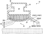
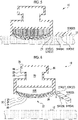
- Figs. 4 and 5 are cross-sectional views taken along the line A-A of Fig. 3 , and Fig. 4 shows a case where the stethoscope 10 is not pressed against the living body 12, and Fig. 5 shows a case where the stethoscope 10 is pressed against the living body 12.
- the electrocardiographic electrode 50 in order for the electrocardiographic electrode 50 to detect the cardiac electrical activity of the living body 12 with sufficient accuracy, the electrocardiographic electrode 50 needs to have a predetermined area. In addition, with the three electrocardiographic electrodes 50 disposed sufficiently apart from each other, a myoelectric influence of the living body 12 can be eliminated, and the cardiac electrical activity can be detected with a high SN ratio.
- the elastic member 52P has a second connection side 57P that is connected to the first connection side 27P of the support base 20, as a side defining the second contact surface 54P.
- the length of the second connection side 57P is equal to the length of the first connection side 27P.
- the elastic member 52M has a second connection side 57M that is connected to the first connection side 27M of the support base 20, as a side defining the second contact surface 54M.
- the length of the second connection side 57M is equal to the length of the first connection side 27M.
- the elastic member 52R has a second connection side 57R that is connected to the first connection side 27R of the support base 20, as a side defining the second contact surface 54R.
- the length of the second connection side 57R is equal to the length of the first connection side 27R.
- the second connection sides 57P, 57M, and 57R are referred to as a second connection side 57.
- the term "equal” is not limited to a case of being completely equal thereto, and the length need only be a length in which the second connection side 57 is stably connected to the first connection side 27, for example, may be a length having a difference of about ⁇ 10%.
- the elastic member 52 has a shape that is tapered in a direction away from the second connection side 57.
- the first contact surface 24 and the second contact surface 54R of the elastic member 52R are formed so as to extend in the same plane, in a case where a pressing force with which the first contact surface 24 of the support base 20 is pressed against the living body 12 is applied to the stethoscope 10.
- the elastic member 52 has a Young's modulus of 0.2 MPa or more and 50 MPa or less, and the support base 20 is formed of a member harder than the elastic member 52. Therefore, the elastic member 52 can be bent such that the first contact surface 24 and the second contact surface 54 extend in the same plane, with the first connection side 27 and the second connection side 57 as a starting point. In this case, since a bias force acts in a direction of pressing the second contact surface 54 against the living body 12, the electrocardiographic electrode 50 and the living body 12 can be brought into close contact with each other, and the cardiac electrical activity can be detected with a high SN ratio.
- the surface of the piezoelectric film 30, which is exposed from the opening portion 22, is convexly curved, it is possible to increase the expansion and contraction of the piezoelectric film 30 in the in-plane direction as compared with a case where the piezoelectric film 30 is provided in a flat shape. That is, with the piezoelectric film 30 supported by the support base 20 in a state in which the surface exposed from the opening portion 22 is convexly curved, it is possible to increase the amplitude of the voltage that is detected by the piezoelectric film 30 and a sound can be collected with a high SN ratio.
- a space between the piezoelectric film 30 and the support base 20 is filled with a cushioning material 38A, and the piezoelectric film 30 is supported by the cushioning material 38A so as to be convexly curved.
- the cushioning material 38A has appropriate elasticity, and supports the piezoelectric film 30 and imparts a constant mechanical bias to the entire surface of the piezoelectric film 30.
- the vibration in the thickness direction, which is generated in the piezoelectric film 30 can be converted into an expansion/contraction motion in the in-plane direction of the piezoelectric film 30, and the electric charge generation efficiency can be improved.
- the filling density of the cushioning material 38A is changed, so that a stethoscope 10 having an appropriate repulsive force can be realized.
- the piezoelectric film 30 comprises a piezoelectric layer 32 that has a first main surface 32A which is a main surface on a side of the living body 12 and a second main surface 32B which is a main surface opposite to the side of the living body 12, as two main surfaces facing each other, a first electrode 34 provided on the first main surface 32A, and a second electrode 36 provided on the second main surface 32B.
- the matrix is preferably a polymer material having viscoelasticity at a room temperature, such as cyanoethylated polyvinyl alcohol (cyanoethylated PVA), polyvinyl acetate, polyvinylidene chloride core acrylonitrile, a polystyrene-vinyl polyisoprene block copolymer, polyvinyl methyl ketone, and polybutyl methacrylate.
- cyanoethylated polyvinyl alcohol cyanoethylated PVA
- polyvinyl acetate polyvinylidene chloride core acrylonitrile
- a polystyrene-vinyl polyisoprene block copolymer polyvinyl methyl ketone
- polybutyl methacrylate cyanoethylated polyvinyl alcohol
- the piezoelectric particle 33 is a particle of a piezoelectric material, and is preferably a ceramic particle having a perovskite-type crystal structure.
- Examples of the piezoelectric particle include lead zirconate titanate, lead lanthanum zirconate titanate, barium titanate, and a solid solution of barium titanate and bismuth ferrite.
- an organic piezoelectric film such as polyvinylidene fluoride (PVDF), vinylidene-ethylene trifluoride copolymer (P(VDF-TrFE)), or polylactic acid may be used.
- PVDF polyvinylidene fluoride
- P(VDF-TrFE) vinylidene-ethylene trifluoride copolymer
- polylactic acid polylactic acid
- an organic material such as a polymer electret material containing, as a main component, a polymer described in JP2018-191394A , JP2014-233688A , and JP2017-12270A may be used.
- the piezoelectric layer 32 instead of the polymer-based piezoelectric composite material, dielectric polarization occurs in the in-plane direction.
- the SN ratio may decrease as compared with the polymer-based piezoelectric composite material in which dielectric polarization occurs in the thickness direction.
- the first electrode 34 and the second electrode 36 detect the expansion and contraction in the in-plane direction, which is generated in the piezoelectric layer 32, as a voltage.
- the thickness of each of the first electrode 34 and the second electrode 36 is not particularly limited, but is preferably thin in order to ensure the flexibility of the piezoelectric film 30, and is preferably 1 ⁇ m or less, for example.
- the thicknesses of the first electrode 34 and the second electrode 36 may be the same or different from each other.
- the material of the first electrode 34 and the second electrode 36 is a thin film of copper (Cu) or aluminum (Al) formed by vacuum deposition in order to ensure the flexibility of the piezoelectric film 30, a conductive polymer, and the like.
- Various conductors may be used as the material of the first electrode 34 and the second electrode 36.
- C, Pd, Fe, Sn, Ni, Pt, Au, Ag, Cr, and Mo, and an alloy thereof may be used.
- a transparent conductive film such as indium tin oxide (ITO), indium zinc oxide (IZO), tin oxide, and zinc oxide may be used.
- an organic conductor such as a conductive polymer may be used.
- a forming method of the electrode is also not particularly limited, and various known methods, for example, film formation by a vapor deposition method (vacuum film forming method) such as vacuum deposition and sputtering, screen printing, and a method of pasting a foil formed of the above-described materials may be used.
- a vapor deposition method vacuum film forming method
- sputtering screen printing
- a method of pasting a foil formed of the above-described materials may be used.
- the size of at least one of the first electrode 34 or the second electrode 36 may be smaller than that of the piezoelectric layer 32.
- the first electrode 34 is preferably provided only in a central portion of the first main surface 32A.
- the first electrode 34 may function as an antenna and take in electromagnetic noise from an outside. In order to restrain the first electrode 34 from taking in electromagnetic noise, it is preferable to reduce the size of the first electrode 34 within a range in which it is difficult to take in electromagnetic noise and a body sound can be sufficiently detected.
- the first electrode 34 provided only in the central portion of the first main surface 32A that comes into contact with the living body 12 it is possible to restrain the first electrode 34 from taking in electromagnetic noise and a sound can be collected with a high SN ratio.
- the piezoelectric film 30 Since the surface of the piezoelectric film 30, which is exposed from the opening portion 22, is convexly curved and protrudes with respect to the first contact surface 24, the piezoelectric film 30 is easily damaged in a case where the piezoelectric film 30 is brought into direct contact with the living body 12, as compared with the case the piezoelectric film 30 is provided in a flat shape. Therefore, it is preferable to dispose the protective layer 40 on the surface of the piezoelectric film 30 on the side that comes into contact with the living body 12. With the protective layer 40 disposed on the surface of the piezoelectric film 30 on the side that comes into contact with the living body 12, damage to the piezoelectric film 30 can be prevented.
- Fig. 9 is a graph in which the SN ratio of a sound signal S2 (details will be described later) that is output from the stethoscope 10 is measured in a case where the acoustic impedance of the protective layer 40 is changed.
- the horizontal axis represents the acoustic impedance (MRayls) of the protective layer 40
- the vertical axis represents the SN ratio (dB) of the sound signal S2.
- the acoustic impedance of the living body 12 is known to be 1.3 to 1.5 MRayls, and the acoustic impedance of the piezoelectric film 30 is 5.0 to 10.0 MRayls.
- the protective layer 40 has an acoustic impedance of 1.3 MRayls or more and 5.0 MRayls or less between the acoustic impedance of the living body 12 and the acoustic impedance of the piezoelectric film 30, as shown in Fig. 9 , the SN ratio of the sound signal S2 that is output from the stethoscope 10 can be stably made to 60 dB or more.
- the protective layer 40 Since the protective layer 40 is directly pressed against the living body 12, it is desired to have abrasion resistance. Therefore, it is preferable that the protective layer 40 has a measured value of 50 or more and 100 or less in a hardness test using a type A durometer conforming to ASTM D2240. A hardness measured by a durometer of another standard or another measuring method may be used to obtain the same hardness as the hardness in the above-described test method. With the protective layer 40 made to have a hardness in the above-described range, appropriate abrasion resistance for use as a stethoscope can be obtained.
- the thickness of the protective layer 40 having the above-described material and hardness may be appropriately set according to performance, handleability, mechanical strength, and the like required for the piezoelectric film 30. Specifically, the thickness need only be about 500 ⁇ m.
- a surface of the protective layer 40, which comes into contact with the living body 12, is preferably roughened. Since the protective layer 40 is directly pressed against the living body 12, it is desirable that the protective layer 40 is easily peeled off from the skin of the living body 12.
- the roughening treatment method is not particularly limited, and various known methods such as mechanical roughening treatment, electrochemical roughening treatment, and chemical roughening treatment may be used.
- an arithmetic average roughness Ra is preferably 0.1 ⁇ m or more and 100 ⁇ m or less, and more preferably 0.1 ⁇ m or more and 10 ⁇ m or less.
- the protective layer 40 may be a layer of which the acoustic impedance is graded so that the acoustic impedance becomes lower toward the side that comes into contact with the living body 12.
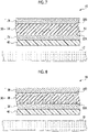
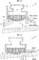
- the protective layer 40 may be formed of a plurality of layers that are laminated so that the acoustic impedance becomes lower toward a layer on the side that comes into contact with the living body 12. For example, as shown in Fig. 10 , in a case where the protective layer 40 is formed of four layers, the acoustic impedance need only become lowered in the order of the protective layers 41, 42, 43, and 44.
- the surface of the protective layer 40 which comes into contact with the living body 12, may consist of a silicone resin, and the silicone resin may have a siloxane skeleton as a main chain skeleton and at least one of a methyl group, a vinyl methyl group, or a phenyl methyl group, as a hydrophobic side chain.
- the surface of the living body 12 may be wet due to sweat or the like. Since the protective layer 40 is directly pressed against the living body 12, it is desired that at least the surface that comes into contact with the living body 12 is made of a material that is not denatured by moisture. Therefore, for example, as shown in Fig.
- the protective layer 40 may be formed of a protective layer 46 of which the acoustic impedance is adjusted, and a protective layer 47 which is a surface that comes into contact with the living body 12 and which consists of a hydrophobic material. With the surface having hydrophobicity, which comes into contact with the living body 12, it is possible to restrain the protective layer 40 and the piezoelectric film 30 from being denatured even in a case where the protective layer 40 is pressed against the wet living body 12.
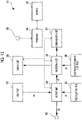
- the stethoscope 10 comprises the piezoelectric film 30, the electrocardiographic electrode 50, the output terminal 80, an input unit 82, the display unit 84, and the charging terminal 86. Further, the stethoscope 10 comprises an output unit 60, a processing unit 90, a communication unit 92, a power unit 94, and a battery 96.
- the output unit 60, the processing unit 90, the communication unit 92, the power unit 94, and the battery 96 may be housed in a housing portion 29, which is a space of the support base 20 (see Fig. 4 ), and may be provided outside the support base 20.
- the piezoelectric film 30 detects the vibration caused by the body sound which is generated from the living body 12, and outputs a vibration signal S1 to the output unit 60 on the basis of the vibration. Specifically, in a case where a surface of the living body 12 is vibrated due to the body sound that is generated from the living body 12, when the living body 12 is brought into contact with the piezoelectric film 30, the piezoelectric film 30 is also vibrated in response to the vibration. The piezoelectric film 30 detects the vibration as a voltage that is generated between the first electrode 34 and the second electrode 36, and outputs the detected voltage to the output unit 60 as the vibration signal S1.
- the input unit 82 receives an adjustment input of a level of the sound signal S2 that is output from the output unit 60, which will be described later, and outputs an adjustment input signal S4 indicating the received adjustment input information, to the output unit 60.
- the output unit 60 outputs the sound signal S2 to the processing unit 90 on the basis of the vibration signal S1. Further, the output unit 60 adjusts the level of the sound signal S2 according to a level change of the vibration signal S1 and the adjustment input signal S4, and outputs the adjusted signal to the output terminal 80 as the adjustment signal S3.
- the output terminal 80 outputs the adjustment signal S3 to the outside.
- the electrocardiographic electrode 50 detects the cardiac electrical activity of the living body 12. Specifically, in a case where the electrocardiographic electrode 50 is brought into contact with the vicinity of the heart of the living body 12, the electrocardiographic electrode 50 detects potential on a body surface of the living body 12 and outputs the detected potential to the processing unit 90 as an electrocardiographic signal S5.
- the processing unit 90 performs predetermined processing on data based on the sound signal S2 and the electrocardiographic signal S5, and outputs the processed data to the communication unit 92.
- the processing unit 90 may comprise an amplifier circuit, a filter circuit, and the like, and may amplify the sound signal S2 and the electrocardiographic signal S5 or extract a specific frequency. Further, the data based on the sound signal S2 and the electrocardiographic signal S5 may be output as analog data or digital data.
- the processing unit 90 may be formed by, for example, a microcomputer including a central processing unit (CPU) 60, a read only memory (ROM), and a random access memory (RAM).
- the communication unit 92 comprises a wired or wireless communication means, and transmits a body sound and electrocardiographic data to an external device.
- the communication means may be, for example, Bluetooth (registered trademark) or infrared communication
- the external device may be, for example, a personal computer or a smartphone.
- the power unit 94 charges the battery 96 with electric power that is supplied from the charging terminal 86. Further, the power unit 94 supplies the electric power with which the battery 96 is charged to the output unit 60, the display unit 84, the processing unit 90, and the communication unit 92.
- the processing unit 90 acquires information indicating the remaining battery level of the battery 96 via the power unit 94, and may perform control, such as making LED light of the display unit 84 turned on or off, or blink on and off, on the basis of the acquired information. In this case, the user can grasp the remaining battery level of the battery 96 from a light emitting state of the LED light.
- the processing unit 90 may control the display unit 84 in a case where the sound signal S2 and the electrocardiographic signal S5 are normally acquired. In this case, the user can grasp an acquisition state of the sound signal S2 and the electrocardiographic signal S5 from a display mode of the display unit 84.
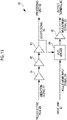
- the output unit 60 comprises a buffer 61, a filter circuit 62, amplifiers 63 and 65, and an automatic level control (ALC) circuit 64.
- ALC automatic level control
- the piezoelectric film 30 is vibrated greatly, and sharp noise (spike noise) may be mixed into the vibration signal S1.
- spike noise is output as the sound signal S2 from the output terminal 80 as it is, the sound heard from the earphone that is connected to the output terminal 80 becomes a harsh sound. Therefore, it is desirable to reduce the spike noise by the ALC circuit 64.
- the sound signal S2 of which the spike noise is reduced and the level is adjusted by the ALC circuit 64 is amplified by the amplifier 65 and output to the output terminal 80 as the adjustment signal S3.
- the piezoelectric film 30 is supported by the support base 20 in a state in which the surface exposed from the opening portion 22 is convexly curved, and a protective layer 40 having an acoustic impedance between the acoustic impedance of the living body 12 and the acoustic impedance of the piezoelectric film 30 is provided on the surface of the piezoelectric film 30 on the side which comes into contact with the living body 12. Therefore, the body sound can be detected with a high SN ratio.
- the output terminal 80 is disposed on the axis passing through the center of the one predetermined electrocardiographic electrode out of the three electrocardiographic electrodes 50, and the center of the piezoelectric film 30. Therefore, the operability of the user can be improved.
- the piezoelectric film 30 can easily detect sounds from the outside, such as environmental sounds and human voices, (hereinafter, referred to as an external sound) as noise, and the SN ratio decreases.
Landscapes
- Health & Medical Sciences (AREA)
- Life Sciences & Earth Sciences (AREA)
- Physics & Mathematics (AREA)
- Engineering & Computer Science (AREA)
- Acoustics & Sound (AREA)
- Veterinary Medicine (AREA)
- Public Health (AREA)
- General Health & Medical Sciences (AREA)
- Biomedical Technology (AREA)
- Heart & Thoracic Surgery (AREA)
- Medical Informatics (AREA)
- Molecular Biology (AREA)
- Surgery (AREA)
- Animal Behavior & Ethology (AREA)
- Pathology (AREA)
- Biophysics (AREA)
- Signal Processing (AREA)
- Cardiology (AREA)
- Multimedia (AREA)
- Mechanical Engineering (AREA)
- General Physics & Mathematics (AREA)
- Chemical & Material Sciences (AREA)
- Composite Materials (AREA)
- Materials Engineering (AREA)
- Measurement And Recording Of Electrical Phenomena And Electrical Characteristics Of The Living Body (AREA)
- Piezo-Electric Transducers For Audible Bands (AREA)
- Measuring Pulse, Heart Rate, Blood Pressure Or Blood Flow (AREA)
Applications Claiming Priority (2)
| Application Number | Priority Date | Filing Date | Title |
|---|---|---|---|
| JP2019138272 | 2019-07-26 | ||
| PCT/JP2020/028081 WO2021020203A1 (ja) | 2019-07-26 | 2020-07-20 | 聴診器 |
Publications (2)
| Publication Number | Publication Date |
|---|---|
| EP4005488A1 true EP4005488A1 (de) | 2022-06-01 |
| EP4005488A4 EP4005488A4 (de) | 2022-08-24 |
Family
ID=74230297
Family Applications (1)
| Application Number | Title | Priority Date | Filing Date |
|---|---|---|---|
| EP20846462.8A Withdrawn EP4005488A4 (de) | 2019-07-26 | 2020-07-20 | Stethoskop |
Country Status (6)
| Country | Link |
|---|---|
| US (1) | US20220142602A1 (de) |
| EP (1) | EP4005488A4 (de) |
| JP (1) | JP7242863B2 (de) |
| CN (1) | CN114206221A (de) |
| TW (1) | TW202114599A (de) |
| WO (1) | WO2021020203A1 (de) |
Families Citing this family (5)
| Publication number | Priority date | Publication date | Assignee | Title |
|---|---|---|---|---|
| WO2020137212A1 (ja) * | 2018-12-26 | 2020-07-02 | 富士フイルム株式会社 | 聴診器および電子聴診装置 |
| CN116867438A (zh) * | 2021-02-26 | 2023-10-10 | 富士胶片株式会社 | 电子听诊器 |
| USD1068081S1 (en) | 2023-04-26 | 2025-03-25 | Eko Health, Inc. | Chestpiece |
| USD1069113S1 (en) * | 2023-04-26 | 2025-04-01 | Eko Health, Inc. | Chestpiece |
| USD1080869S1 (en) * | 2023-04-26 | 2025-06-24 | Eko Health, Inc. | Chestpiece |
Family Cites Families (17)
| Publication number | Priority date | Publication date | Assignee | Title |
|---|---|---|---|---|
| US4903794A (en) * | 1988-03-23 | 1990-02-27 | Klippert Don H | Acoustical amplifying stethoscope |
| KR19990028685A (ko) * | 1995-07-06 | 1999-04-15 | 프레들린 보에쎌,페로이 칼린 | 전자 청진기 |
| JPH10300594A (ja) * | 1997-04-21 | 1998-11-13 | Olympus Optical Co Ltd | 触覚センサ |
| JP2004298619A (ja) | 2003-03-20 | 2004-10-28 | Seiko Instruments Inc | センサデバイスの劣化検出装置、劣化検出方法および劣化検出システム |
| JP4848524B2 (ja) | 2005-10-21 | 2011-12-28 | 国立大学法人山口大学 | 聴診心音信号の処理方法及び聴診装置 |
| JP5603789B2 (ja) | 2011-01-26 | 2014-10-08 | 旭化成株式会社 | 体内音取得装置、及び、それを備えた電子聴診器 |
| JP2014124412A (ja) | 2012-12-27 | 2014-07-07 | Jvc Kenwood Corp | 生体音集音装置、及び生体音集音装置を備える電子聴診装置 |
| JP2014233688A (ja) | 2013-06-04 | 2014-12-15 | 東洋紡株式会社 | エレクトレットフィルター |
| JP6675897B2 (ja) | 2015-03-24 | 2020-04-08 | Jrcs株式会社 | 電子聴診器 |
| JP6520470B2 (ja) | 2015-06-29 | 2019-05-29 | 富士通株式会社 | フィルム型圧力センサ及びその製造方法 |
| WO2017069055A1 (ja) * | 2015-10-21 | 2017-04-27 | 富士フイルム株式会社 | 映像音響システム |
| JP6510148B2 (ja) * | 2016-07-27 | 2019-05-08 | 富士フイルム株式会社 | ピックアップセンサおよび生体センサ |
| US10850308B2 (en) * | 2017-02-24 | 2020-12-01 | Sensus Spectrum, Llc | Ultrasonic device including acoustically matched regions therein |
| JP6915367B2 (ja) | 2017-04-28 | 2021-08-04 | 住友電気工業株式会社 | 発電デバイス |
| US20190069873A1 (en) | 2017-09-06 | 2019-03-07 | Ryan J. Copt | Auscultation of a body |
| CN107456244B (zh) * | 2017-09-15 | 2024-03-26 | 清华大学 | 肠鸣音采集装置 |
| JP6660410B2 (ja) | 2018-02-14 | 2020-03-11 | 株式会社Subaru | パージシステムの故障診断装置 |
-
2020
- 2020-07-20 CN CN202080053676.0A patent/CN114206221A/zh active Pending
- 2020-07-20 WO PCT/JP2020/028081 patent/WO2021020203A1/ja not_active Ceased
- 2020-07-20 JP JP2021536962A patent/JP7242863B2/ja active Active
- 2020-07-20 EP EP20846462.8A patent/EP4005488A4/de not_active Withdrawn
- 2020-07-20 TW TW109124366A patent/TW202114599A/zh unknown
-
2022
- 2022-01-20 US US17/579,616 patent/US20220142602A1/en not_active Abandoned
Also Published As
| Publication number | Publication date |
|---|---|
| JP7242863B2 (ja) | 2023-03-20 |
| CN114206221A (zh) | 2022-03-18 |
| EP4005488A4 (de) | 2022-08-24 |
| US20220142602A1 (en) | 2022-05-12 |
| TW202114599A (zh) | 2021-04-16 |
| WO2021020203A1 (ja) | 2021-02-04 |
| JPWO2021020203A1 (de) | 2021-02-04 |
Similar Documents
| Publication | Publication Date | Title |
|---|---|---|
| US20220142602A1 (en) | Stethoscope | |
| US20230071365A1 (en) | Stethoscope | |
| US20220142604A1 (en) | Stethoscope | |
| EP3903684B1 (de) | Stethoskop und elektronische stethoskopvorrichtung | |
| US9192351B1 (en) | Acoustic respiratory monitoring sensor with probe-off detection | |
| CN101321497B (zh) | 悬臂式生物声学传感器及其使用方法 | |
| US12082935B2 (en) | Disposable health and vital signs monitoring patch and making of same | |
| JP5509422B2 (ja) | 生体音取得端末、電子聴診器および生体音測定装置 | |
| US20190343452A1 (en) | Bruxism monitoring and prevention system | |
| US12507965B2 (en) | Systems and methods for power management of an electronic stethoscope | |
| US20220142603A1 (en) | Stethoscope | |
| CN1172632C (zh) | 拾音传感器 | |
| JP5467265B2 (ja) | 体導音センサ | |
| CN204364227U (zh) | 一种可穿戴柔性电子创可贴及人体健康检测系统 | |
| CN119816251A (zh) | 用于方便收集源自生物体内的声波的管状构件 | |
| JP3187112U (ja) | 生体モニター装置 | |
| CN117379078B (zh) | 一种可贴附式人体声频采集设备及人体声频采集分析系统 | |
| JP7772637B2 (ja) | 電子聴診器 | |
| CN214017583U (zh) | 一种无线baep信号采集装置 |
Legal Events
| Date | Code | Title | Description |
|---|---|---|---|
| STAA | Information on the status of an ep patent application or granted ep patent |
Free format text: STATUS: THE INTERNATIONAL PUBLICATION HAS BEEN MADE |
|
| PUAI | Public reference made under article 153(3) epc to a published international application that has entered the european phase |
Free format text: ORIGINAL CODE: 0009012 |
|
| STAA | Information on the status of an ep patent application or granted ep patent |
Free format text: STATUS: REQUEST FOR EXAMINATION WAS MADE |
|
| 17P | Request for examination filed |
Effective date: 20220124 |
|
| AK | Designated contracting states |
Kind code of ref document: A1 Designated state(s): AL AT BE BG CH CY CZ DE DK EE ES FI FR GB GR HR HU IE IS IT LI LT LU LV MC MK MT NL NO PL PT RO RS SE SI SK SM TR |
|
| A4 | Supplementary search report drawn up and despatched |
Effective date: 20220727 |
|
| RIC1 | Information provided on ipc code assigned before grant |
Ipc: G10K 11/02 20060101ALI20220722BHEP Ipc: A61B 7/04 20060101AFI20220722BHEP |
|
| DAV | Request for validation of the european patent (deleted) | ||
| DAX | Request for extension of the european patent (deleted) | ||
| STAA | Information on the status of an ep patent application or granted ep patent |
Free format text: STATUS: THE APPLICATION HAS BEEN WITHDRAWN |
|
| 18W | Application withdrawn |
Effective date: 20240405 |