EP4005493A1 - Procédé d'obtention de propriétés élastiques d'un solide mou qui fait appel à des vortex acoustiques - Google Patents
Procédé d'obtention de propriétés élastiques d'un solide mou qui fait appel à des vortex acoustiques Download PDFInfo
- Publication number
- EP4005493A1 EP4005493A1 EP20843425.8A EP20843425A EP4005493A1 EP 4005493 A1 EP4005493 A1 EP 4005493A1 EP 20843425 A EP20843425 A EP 20843425A EP 4005493 A1 EP4005493 A1 EP 4005493A1
- Authority
- EP
- European Patent Office
- Prior art keywords
- soft solid
- ultrasound transducer
- transducer
- ultrasound
- wave front
- Prior art date
- Legal status (The legal status is an assumption and is not a legal conclusion. Google has not performed a legal analysis and makes no representation as to the accuracy of the status listed.)
- Withdrawn
Links
Images



Classifications
-
- A—HUMAN NECESSITIES
- A61—MEDICAL OR VETERINARY SCIENCE; HYGIENE
- A61B—DIAGNOSIS; SURGERY; IDENTIFICATION
- A61B8/00—Diagnosis using ultrasonic, sonic or infrasonic waves
- A61B8/44—Constructional features of the ultrasonic, sonic or infrasonic diagnostic device
-
- A—HUMAN NECESSITIES
- A61—MEDICAL OR VETERINARY SCIENCE; HYGIENE
- A61B—DIAGNOSIS; SURGERY; IDENTIFICATION
- A61B8/00—Diagnosis using ultrasonic, sonic or infrasonic waves
- A61B8/48—Diagnostic techniques
- A61B8/485—Diagnostic techniques involving measuring strain or elastic properties
-
- A—HUMAN NECESSITIES
- A61—MEDICAL OR VETERINARY SCIENCE; HYGIENE
- A61B—DIAGNOSIS; SURGERY; IDENTIFICATION
- A61B8/00—Diagnosis using ultrasonic, sonic or infrasonic waves
- A61B8/08—Clinical applications
- A61B8/0833—Clinical applications involving detecting or locating foreign bodies or organic structures
-
- A—HUMAN NECESSITIES
- A61—MEDICAL OR VETERINARY SCIENCE; HYGIENE
- A61B—DIAGNOSIS; SURGERY; IDENTIFICATION
- A61B8/00—Diagnosis using ultrasonic, sonic or infrasonic waves
- A61B8/44—Constructional features of the ultrasonic, sonic or infrasonic diagnostic device
- A61B8/4483—Constructional features of the ultrasonic, sonic or infrasonic diagnostic device characterised by features of the ultrasound transducer
- A61B8/4488—Constructional features of the ultrasonic, sonic or infrasonic diagnostic device characterised by features of the ultrasound transducer the transducer being a phased array
-
- A—HUMAN NECESSITIES
- A61—MEDICAL OR VETERINARY SCIENCE; HYGIENE
- A61B—DIAGNOSIS; SURGERY; IDENTIFICATION
- A61B8/00—Diagnosis using ultrasonic, sonic or infrasonic waves
- A61B8/44—Constructional features of the ultrasonic, sonic or infrasonic diagnostic device
- A61B8/4483—Constructional features of the ultrasonic, sonic or infrasonic diagnostic device characterised by features of the ultrasound transducer
- A61B8/4494—Constructional features of the ultrasonic, sonic or infrasonic diagnostic device characterised by features of the ultrasound transducer characterised by the arrangement of the transducer elements
-
- A—HUMAN NECESSITIES
- A61—MEDICAL OR VETERINARY SCIENCE; HYGIENE
- A61B—DIAGNOSIS; SURGERY; IDENTIFICATION
- A61B8/00—Diagnosis using ultrasonic, sonic or infrasonic waves
- A61B8/48—Diagnostic techniques
- A61B8/488—Diagnostic techniques involving Doppler signals
-
- A—HUMAN NECESSITIES
- A61—MEDICAL OR VETERINARY SCIENCE; HYGIENE
- A61B—DIAGNOSIS; SURGERY; IDENTIFICATION
- A61B8/00—Diagnosis using ultrasonic, sonic or infrasonic waves
- A61B8/52—Devices using data or image processing specially adapted for diagnosis using ultrasonic, sonic or infrasonic waves
- A61B8/5215—Devices using data or image processing specially adapted for diagnosis using ultrasonic, sonic or infrasonic waves involving processing of medical diagnostic data
- A61B8/5223—Devices using data or image processing specially adapted for diagnosis using ultrasonic, sonic or infrasonic waves involving processing of medical diagnostic data for extracting a diagnostic or physiological parameter from medical diagnostic data
-
- A—HUMAN NECESSITIES
- A61—MEDICAL OR VETERINARY SCIENCE; HYGIENE
- A61B—DIAGNOSIS; SURGERY; IDENTIFICATION
- A61B8/00—Diagnosis using ultrasonic, sonic or infrasonic waves
- A61B8/52—Devices using data or image processing specially adapted for diagnosis using ultrasonic, sonic or infrasonic waves
- A61B8/5215—Devices using data or image processing specially adapted for diagnosis using ultrasonic, sonic or infrasonic waves involving processing of medical diagnostic data
- A61B8/5238—Devices using data or image processing specially adapted for diagnosis using ultrasonic, sonic or infrasonic waves involving processing of medical diagnostic data for combining image data of patient, e.g. merging several images from different acquisition modes into one image
- A61B8/5246—Devices using data or image processing specially adapted for diagnosis using ultrasonic, sonic or infrasonic waves involving processing of medical diagnostic data for combining image data of patient, e.g. merging several images from different acquisition modes into one image combining images from the same or different imaging techniques, e.g. color Doppler and B-mode
-
- G—PHYSICS
- G01—MEASURING; TESTING
- G01N—INVESTIGATING OR ANALYSING MATERIALS BY DETERMINING THEIR CHEMICAL OR PHYSICAL PROPERTIES
- G01N29/00—Investigating or analysing materials by the use of ultrasonic, sonic or infrasonic waves; Visualisation of the interior of objects by transmitting ultrasonic or sonic waves through the object
- G01N29/04—Analysing solids
- G01N29/043—Analysing solids in the interior, e.g. by shear waves
-
- G—PHYSICS
- G01—MEASURING; TESTING
- G01N—INVESTIGATING OR ANALYSING MATERIALS BY DETERMINING THEIR CHEMICAL OR PHYSICAL PROPERTIES
- G01N29/00—Investigating or analysing materials by the use of ultrasonic, sonic or infrasonic waves; Visualisation of the interior of objects by transmitting ultrasonic or sonic waves through the object
- G01N29/22—Details, e.g. general constructional or apparatus details
- G01N29/221—Arrangements for directing or focusing the acoustical waves
-
- G—PHYSICS
- G01—MEASURING; TESTING
- G01N—INVESTIGATING OR ANALYSING MATERIALS BY DETERMINING THEIR CHEMICAL OR PHYSICAL PROPERTIES
- G01N29/00—Investigating or analysing materials by the use of ultrasonic, sonic or infrasonic waves; Visualisation of the interior of objects by transmitting ultrasonic or sonic waves through the object
- G01N29/22—Details, e.g. general constructional or apparatus details
- G01N29/24—Probes
- G01N29/2456—Focusing probes
-
- G—PHYSICS
- G01—MEASURING; TESTING
- G01S—RADIO DIRECTION-FINDING; RADIO NAVIGATION; DETERMINING DISTANCE OR VELOCITY BY USE OF RADIO WAVES; LOCATING OR PRESENCE-DETECTING BY USE OF THE REFLECTION OR RERADIATION OF RADIO WAVES; ANALOGOUS ARRANGEMENTS USING OTHER WAVES
- G01S15/00—Systems using the reflection or reradiation of acoustic waves, e.g. sonar systems
- G01S15/88—Sonar systems specially adapted for specific applications
- G01S15/89—Sonar systems specially adapted for specific applications for mapping or imaging
- G01S15/8906—Short-range imaging systems; Acoustic microscope systems using pulse-echo techniques
- G01S15/8909—Short-range imaging systems; Acoustic microscope systems using pulse-echo techniques using a static transducer configuration
-
- G—PHYSICS
- G01—MEASURING; TESTING
- G01S—RADIO DIRECTION-FINDING; RADIO NAVIGATION; DETERMINING DISTANCE OR VELOCITY BY USE OF RADIO WAVES; LOCATING OR PRESENCE-DETECTING BY USE OF THE REFLECTION OR RERADIATION OF RADIO WAVES; ANALOGOUS ARRANGEMENTS USING OTHER WAVES
- G01S15/00—Systems using the reflection or reradiation of acoustic waves, e.g. sonar systems
- G01S15/88—Sonar systems specially adapted for specific applications
- G01S15/89—Sonar systems specially adapted for specific applications for mapping or imaging
- G01S15/8906—Short-range imaging systems; Acoustic microscope systems using pulse-echo techniques
- G01S15/8909—Short-range imaging systems; Acoustic microscope systems using pulse-echo techniques using a static transducer configuration
- G01S15/8915—Short-range imaging systems; Acoustic microscope systems using pulse-echo techniques using a static transducer configuration using a transducer array
-
- G—PHYSICS
- G01—MEASURING; TESTING
- G01S—RADIO DIRECTION-FINDING; RADIO NAVIGATION; DETERMINING DISTANCE OR VELOCITY BY USE OF RADIO WAVES; LOCATING OR PRESENCE-DETECTING BY USE OF THE REFLECTION OR RERADIATION OF RADIO WAVES; ANALOGOUS ARRANGEMENTS USING OTHER WAVES
- G01S15/00—Systems using the reflection or reradiation of acoustic waves, e.g. sonar systems
- G01S15/88—Sonar systems specially adapted for specific applications
- G01S15/89—Sonar systems specially adapted for specific applications for mapping or imaging
- G01S15/8906—Short-range imaging systems; Acoustic microscope systems using pulse-echo techniques
- G01S15/8909—Short-range imaging systems; Acoustic microscope systems using pulse-echo techniques using a static transducer configuration
- G01S15/8915—Short-range imaging systems; Acoustic microscope systems using pulse-echo techniques using a static transducer configuration using a transducer array
- G01S15/8925—Short-range imaging systems; Acoustic microscope systems using pulse-echo techniques using a static transducer configuration using a transducer array the array being a two-dimensional transducer configuration, i.e. matrix or orthogonal linear arrays
-
- G—PHYSICS
- G01—MEASURING; TESTING
- G01S—RADIO DIRECTION-FINDING; RADIO NAVIGATION; DETERMINING DISTANCE OR VELOCITY BY USE OF RADIO WAVES; LOCATING OR PRESENCE-DETECTING BY USE OF THE REFLECTION OR RERADIATION OF RADIO WAVES; ANALOGOUS ARRANGEMENTS USING OTHER WAVES
- G01S7/00—Details of systems according to groups G01S13/00, G01S15/00, G01S17/00
- G01S7/52—Details of systems according to groups G01S13/00, G01S15/00, G01S17/00 of systems according to group G01S15/00
- G01S7/52017—Details of systems according to groups G01S13/00, G01S15/00, G01S17/00 of systems according to group G01S15/00 particularly adapted to short-range imaging
- G01S7/52023—Details of receivers
- G01S7/52036—Details of receivers using analysis of echo signal for target characterisation
- G01S7/52042—Details of receivers using analysis of echo signal for target characterisation determining elastic properties of the propagation medium or of the reflective target
-
- A—HUMAN NECESSITIES
- A61—MEDICAL OR VETERINARY SCIENCE; HYGIENE
- A61B—DIAGNOSIS; SURGERY; IDENTIFICATION
- A61B8/00—Diagnosis using ultrasonic, sonic or infrasonic waves
- A61B8/44—Constructional features of the ultrasonic, sonic or infrasonic diagnostic device
- A61B8/4483—Constructional features of the ultrasonic, sonic or infrasonic diagnostic device characterised by features of the ultrasound transducer
Definitions
- the present invention relates to a method for obtaining elastic properties of a soft solid by means of quasi-omnidirectional transverse waves generated by a focused vortex ultrasound beam.
- Elastography imaging is a medical imaging modality that allows the elastic properties of soft tissues to be evaluated. These properties make it possible to detect changes in the stiffness of the tissues associated with underlying pathologies.
- Elastography methods propose estimating the elastic properties of tissues by measuring the deformations that are produced when certain external mechanical stress is applied to them.
- the tissue is compressed externally in a manner analogous to palpation, or by externally applying oscillatory compression on the tissue.
- a second generation of methods are those that use the acoustic radiation force produced by a focused ultrasound beam as a mechanism to generate the stress field, wherein the transfer of momentum from the wave to the tissue is due to absorption and reflection on the non-homogeneous areas thereof.
- the deformations produced inside the tissue can be detected.
- Such movements are a few micrometres in amplitude.
- the elastic parameters of the tissue can be calculated by measuring the deformations produced in the tissue when the applied radiation force is known.
- ARFI Acoustic Radiation Force Impulse imaging
- HMI Harmonic Motion Imaging
- shear waves that are generated after the transient application of the primary ultrasound beam. Since shear waves propagate through human tissues at a slow speed (about 1-10 m/s), the deformations produced by the same can be measured by a secondary ultrasound beam.
- Shear Wave Elastography Imaging from the document Shear wave elasticity imaging: a new ultrasonic technology of medical diagnostics by Sarvazyan, A. P., Rudenko, O. V., Swanson, S. D., Fowlkes, J. B., & Emelianov, S. Y. Ultrasound in medicine & biology, 24(9), 1419-1435 (1998 ), showing a technique to determine the elastic properties of a tissue based on the use of acoustic radiation force to excite it.
- the acoustic radiation force is exerted in the axial direction, but in this case a spatial excitation pattern is defined, i.e., the tissue is excited at different points.
- Supersonic shear imaging is featured in the document Supersonic Shear Imaging: A New Technique for Soft Tissue Elasticity Mapping by Jéremy Bercoff, Mickäel Tanter, and Mathias Fink; IEEE transactions on ultrasonics, ferroelectrics, and frequency control, vol. 51, no. 4, April 2004 .
- This document proposes a new technique for generating transverse waves in biological tissue.
- the technique consists of using the radiation force exerted by an ultrasound beam that is focused on different points of the tissue at a speed greater than the propagation speed of the transverse waves generated in the tissue. This generates a Mach cone with transverse waves of greater amplitude, due to the constructive interference that is generated in the wave fronts.
- the transverse waves are generated in the direction perpendicular to the primary ultrasound beam. In this way, the area on the axis of the primary beam is left unscanned since transverse waves are not generated in that direction. Since a focused ultrasound beam that only carries linear momentum is used in these techniques, the stresses produced are only produced in the direction of the axial beam.
- spiral grids such as those described in the documents Sharp acoustic vortex focusing by Fresnel-spiral zone plates by Jimenez, N., Romero-Garcia, V., Garc ⁇ a-Raffi, L. M., Camarena, F., & Staliunas, K. Applied Physics Letters, 112(20), 204101. (2018 ) and in the document Formation of high-order acoustic Bessel beams by spiral diffraction gratings by Jimenez, N., Pico, R., Sanchez-Morcillo, V., Romero-Garcia, V., Garcia-Raffi, L. M., & Staliunas, K.; Physical Review E, 94(5), 053004. (2016 ).
- the radiation force applied in all currently available elastography techniques has the direction of the generated excitation beam, so that the radiation pattern of the transverse waves is limited, the excitation frequency cannot be defined and the amplitude of the generated transverse waves is low.
- the present invention provides an improvement with respect to prior methods by broadening the radiation pattern of the generated transverse waves, allowing the excitation frequency of the transverse waves to be defined, and increasing the amplitude of the generated transverse waves.
- the invention is based on the use of a vortex ultrasound beam that produces a torsional stress field, which generates a transverse wave front inside a soft solid, and which is used to determine a series of elastic properties of said soft solid, which is preferably a tissue, such as liver or prostate, from a patient to be diagnosed.
- a quasi-omnidirectional transverse wave front is generated from a focused ultrasound beam, with a helical phase profile, i.e., an acoustic vortex, the wave front propagating through the soft solid, so that all areas of interest around the ultrasound beam are covered.
- the amplitude of the generated waves is greater for one same acoustic intensity, which allows the signal-to-noise ratio of the image to be improved and the amplitude level of the beam to be reduced, thus reducing unwanted effects such as the increase in temperature produced by the primary beam.
- the control of the direction of rotation allows the polarisation of the transverse waves to be controlled, allowing the anisotropy of the tissues to be evaluated, as occurs, for example, in fibrous tissues.
- this method is used to obtain the elastic properties of a patient's tissue.
- the information obtained on the elastic properties of the tissue is used to make a medical diagnosis and detect possible anomalies in said tissue, which may be the consequence of cancer or some other type of injury, and which are accompanied by changes in the elastic properties of the tissues.
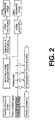
- the first step of the method consists of applying a pulsed or amplitude-modulated signal to an ultrasound transducer that has a surface intended to make contact with the tissue to be studied.
- This signal is comprised in the ultrasound range (with a carrier frequency between 0.2 MHz and 20 MHz). Specifically, it would be a sinusoidal signal with a modulation frequency equal to that of the transverse wave front to be generated.
- a focused vortex ultrasound beam is generated, which in turn generates a quasi-omnidirectional transverse wave front that is transmitted through the soft solid.
- the ultrasound transducer used can be of two different types, and depending on which one is used, the strategy to generate the acoustic vortex will be different.
- a single element transducer comprising a holographic lens.
- Said lens is intended to be positioned on the surface ( x 0 , y 0 ) of the ultrasound transducer.
- the wave front is characterised in that it has a complex amplitude A ( x 0 , y 0 ), which is modified by the lens, such that it is adjusted to that of a focused acoustic vortex.
- a x 0 y 0 exp ⁇ ik 0 x 0 2 + y 0 2 + F 2 ⁇ exp ⁇ im tan ⁇ 1 y 0 x 0 , wherein A ( x 0 , y 0 ) is the complex amplitude along the surface of the ultrasound transducer given by x 0 , y 0 .
- F is the focal length of the lens and m the topological charge of the vortex, which is normally an integer. Depending on the sign of m, the vortex rotates clockwise or anticlockwise.
- the lens therefore, must be capable of producing the phase profile A ( x 0 , y 0 ) .
- one strategy is to divide the lens into pixels and define a height for each pixel as h ( x 0 , y 0 ) so that it fulfills:
- a x 0 y 0 2 Ze ⁇ ik 0 d ⁇ h x 0 2 Z cos k L h x 0 + i Z 2 + 1 sin k L h x 0 ,
- a multi-element (or phased-array) ultrasound transducer can be used.
- each element of the transducer will adjust to an amplitude given by
- the coordinates x 0 and y 0 are given by the spatial positions in Cartesian coordinates of each element of the ultrasound transducer.
- the array is a geometric focusing array, as in the case of a multi-element wherein each element is arranged on the surface of a sphere of radius F , the same method is applied as in the previous case, but the expression to use is:
- a x 0 y 0 exp ⁇ im tan ⁇ 1 x 0 y 0 .
- the emitted ultrasound beam has an acoustic intensity that rotates with respect to the angular coordinate, and transfers to the soft solid both an amount of linear momentum in the direction of the ultrasound beam and an angular momentum in the form of a torus around the ultrasound beam.
- F being the force vector field
- ⁇ ( ⁇ ) the acoustic absorption of the soft solid
- ⁇ 2 ⁇ f the angular frequency
- ⁇ 0 the density
- c 0 the speed of ultrasound longitudinal waves
- P the ultrasound pressure field
- P ⁇ the complex conjugate thereof.
- the transverse wave front is generated which propagates not only in the direction perpendicular to the ultrasound beam, but also in the same direction as the ultrasound beam, i.e., a quasi-omnidirectional wave front.
- Another advantage offered by the present invention is that by being able to control the parameters that define the ultrasound beam, the polarisation of the wave front that is generated inside the soft solid can be controlled. Specifically, by controlling the sign of the topological charge of the ultrasound beam, the direction of rotation of the stress produced (clockwise/anticlockwise) can be controlled.
- the topological charge will preferably be equal to one, although if it becomes greater than one, wider force fields with a greater torque are generated.
- the waves are excited in both positive and negative cycles, which manages to induce positive and negative deformation cycles in the soft solid, increasing the amplitude of the generated wave front and, therefore, the robustness and sensitivity of the technique. In this way, there is no need to wait for the soft solid to relax before pushing it back and continuously generating waves.
- the ultrasound transducer is a single element, there are different strategies that allow the sign of the topological charge to be controlled.
- the first consists of using a lens designed to work with a topological charge at one emission frequency and with another topological charge of the opposite sign at another frequency, to alternate between the two.
- the second strategy consists of using two ultrasound transducers, positioned as two concentric rings, each having a different lens, as well as a different topological charge, of opposite signs, and alternating the emission of one and the other.
- control of the frequency and direction of rotation of the ultrasound beam allows the generated transverse wave front to be controlled, which facilitates the performance of elastography studies at different frequencies.
- the next step of the method consists of acquiring radiofrequency signals that are reflected by the soft solid at different instants in time, while said wave front is propagated.
- a second ultrasound medical imaging transducer can be used, in pulse-echo mode. This secondary transducer is used to obtain a series of ultrasound images at different instants in time taken after or during the activation of the primary transducer.
- the next step of the method consists of calculating the deformations using cross-correlation methods or Doppler techniques between the different images. This provides an image of the deformations produced in the tissue as the transverse waves pass through.
- the propagation speed of the transverse wave front is calculated.
- G being the transverse or shear modulus of elasticity and ⁇ the density of the soft solid.
- the density changes very little with respect to the variation suffered by the transverse modulus of elasticity of the soft solid, such that a difference in speed is fundamentally due to a variation in the transverse modulus of elasticity thereof and, therefore, to some type of alteration in the soft solid analysed.
- the first step of the method consists of applying a pulsed or modulated frequency signal, with a carrier frequency of around 1 MHz, comprised in the ultrasound range, and a modulator frequency in the range from 1 Hz to 1000 Hz, to an ultrasound transducer (1), like the one in Figure 1 , comprising a surface intended to make contact with a soft solid.
- a focused ultrasound beam (5) is generated, with a helical phase profile, i.e., an acoustic vortex, and which generates a quasi-omnidirectional transverse wave front (6) that is transmitted through the soft solid.
- the frequency of the wave front (6) is equal to the modulation frequency of the pulsed signal applied to the ultrasound transducer (1).
- the focused vortex ultrasound beam (5) is generated by means of the ultrasound transducer (1) which is multi-element (or phased-array), the array being a geometric focusing array.
- the emitted ultrasound beam (5) has an acoustic intensity that rotates with respect to the angular coordinate, which transfers to the soft solid both an amount of linear momentum in the direction of the ultrasound beam and an angular momentum in the form of a torus around the ultrasound beam (5).
- Figure 3 shows the acoustic field generated by the ultrasound transducer (1).
- Figure 3 shows how a phase singularity is produced on the axis that gives rise to an acoustic vortex.
- the phase also rotates around the focus an integer number of times.
- F being the force vector field
- ⁇ ( ⁇ ) the absorption of the soft solid
- ⁇ the angular frequency
- ⁇ 0 the density
- c 0 the speed of front transverse waves
- P the pressure field produced
- P ⁇ the complex conjugate thereof.
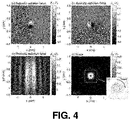
- FIG. 4 This force field is shown in Figure 4 .
- Subgraph e) is the representation of the vector field.
- the next step of the method consists of acquiring radiofrequency signals that are reflected by the soft solid at different instants in time, a process that is repeated while the transverse wave front (6) is propagated.
- a second ultrasound medical imaging transducer (2) is used, in pulse-echo mode.
- G being the transverse or shear modulus of elasticity and ⁇ the density of the soft solid.
Landscapes
- Health & Medical Sciences (AREA)
- Life Sciences & Earth Sciences (AREA)
- Engineering & Computer Science (AREA)
- Physics & Mathematics (AREA)
- General Health & Medical Sciences (AREA)
- Pathology (AREA)
- Public Health (AREA)
- Veterinary Medicine (AREA)
- Animal Behavior & Ethology (AREA)
- Surgery (AREA)
- Biophysics (AREA)
- Nuclear Medicine, Radiotherapy & Molecular Imaging (AREA)
- Molecular Biology (AREA)
- Radiology & Medical Imaging (AREA)
- Biomedical Technology (AREA)
- Heart & Thoracic Surgery (AREA)
- Medical Informatics (AREA)
- Radar, Positioning & Navigation (AREA)
- Remote Sensing (AREA)
- Acoustics & Sound (AREA)
- General Physics & Mathematics (AREA)
- Computer Networks & Wireless Communication (AREA)
- Computer Vision & Pattern Recognition (AREA)
- Analytical Chemistry (AREA)
- Chemical & Material Sciences (AREA)
- Biochemistry (AREA)
- Immunology (AREA)
- Gynecology & Obstetrics (AREA)
- Physiology (AREA)
- Ultra Sonic Daignosis Equipment (AREA)
Applications Claiming Priority (2)
| Application Number | Priority Date | Filing Date | Title |
|---|---|---|---|
| ES201930675A ES2803125B2 (es) | 2019-07-22 | 2019-07-22 | Procedimiento de obtencion de propiedades elasticas de un solido blando que hace uso de vortices acusticos |
| PCT/ES2020/070457 WO2021014040A1 (fr) | 2019-07-22 | 2020-07-14 | Procédé d'obtention de propriétés élastiques d'un solide mou qui fait appel à des vortex acoustiques |
Publications (2)
| Publication Number | Publication Date |
|---|---|
| EP4005493A1 true EP4005493A1 (fr) | 2022-06-01 |
| EP4005493A4 EP4005493A4 (fr) | 2023-01-25 |
Family
ID=74186287
Family Applications (1)
| Application Number | Title | Priority Date | Filing Date |
|---|---|---|---|
| EP20843425.8A Withdrawn EP4005493A4 (fr) | 2019-07-22 | 2020-07-14 | Procédé d'obtention de propriétés élastiques d'un solide mou qui fait appel à des vortex acoustiques |
Country Status (4)
| Country | Link |
|---|---|
| US (1) | US12127887B2 (fr) |
| EP (1) | EP4005493A4 (fr) |
| ES (1) | ES2803125B2 (fr) |
| WO (1) | WO2021014040A1 (fr) |
Families Citing this family (8)
| Publication number | Priority date | Publication date | Assignee | Title |
|---|---|---|---|---|
| TWI803021B (zh) * | 2021-10-20 | 2023-05-21 | 國立成功大學 | 用於生物組織彈性量測的方法、超音波裝置與分析裝置 |
| CN114265048B (zh) * | 2021-11-19 | 2024-12-17 | 中国船舶重工集团公司第七一九研究所 | 一种旋转对称型五模材料低频声波发射装置及试验方法 |
| EP4498922B1 (fr) * | 2022-03-31 | 2025-08-06 | Koninklijke Philips N.V. | Système et procédé de génération d'un indicateur d'interaction d'un dispositif à ultrasons |
| CN114815017A (zh) * | 2022-04-24 | 2022-07-29 | 武汉大学 | 基于声与非均匀流体作用的可调液体透镜及制备方法 |
| CN115372952B (zh) * | 2022-07-08 | 2025-08-22 | 陕西师范大学 | 一种涡旋波束多基地水下目标检测装置与方法 |
| KR102754240B1 (ko) * | 2022-07-14 | 2025-01-15 | 동국대학교 산학협력단 | 청각기능 개선을 위한 에어커플드 볼텍스 초음파 프로브 모듈 및 이를 이용한 초음파 영상화 시스템 |
| CN118483705B (zh) * | 2024-05-11 | 2025-02-14 | 上海交通大学 | 一种基于声涡旋空间相位相关分析的目标探测方法 |
| CN118425321B (zh) * | 2024-07-03 | 2025-01-03 | 四川凯尔迈拓科技有限公司 | 一种相控阵超声检测成像的线性阵列探头布局激励方法 |
Family Cites Families (7)
| Publication number | Priority date | Publication date | Assignee | Title |
|---|---|---|---|---|
| WO2014207668A1 (fr) * | 2013-06-26 | 2014-12-31 | Koninklijke Philips N.V. | Système et procédé de mesure par élastographie |
| JP6430498B2 (ja) * | 2013-06-26 | 2018-11-28 | コーニンクレッカ フィリップス エヌ ヴェKoninklijke Philips N.V. | 超音波剪断波エラストグラフィ測定のマッピングのためのシステムおよび方法 |
| US10775499B2 (en) * | 2014-10-28 | 2020-09-15 | Super Sonic Imagine | Imaging methods and apparatuses for performing shear wave elastography imaging |
| US11103216B2 (en) * | 2014-12-24 | 2021-08-31 | Supersonic Imagine | Shear wave elastography method and apparatus for imaging an anisotropic medium |
| RU2702090C2 (ru) * | 2015-03-31 | 2019-10-04 | Конинклейке Филипс Н.В. | Калибровка ультразвукового, основанного на эластичности, отображения границы очага поражения |
| WO2017223312A1 (fr) * | 2016-06-22 | 2017-12-28 | Duke University | Transducteurs ultrasonores pour interférence constructive par ondes de cisaillement et procédés et systèmes associés |
| CN109261472B (zh) * | 2018-08-30 | 2019-11-08 | 西安交通大学 | 一种空间聚焦涡旋声场的产生装置及方法 |
-
2019
- 2019-07-22 ES ES201930675A patent/ES2803125B2/es active Active
-
2020
- 2020-07-14 EP EP20843425.8A patent/EP4005493A4/fr not_active Withdrawn
- 2020-07-14 WO PCT/ES2020/070457 patent/WO2021014040A1/fr not_active Ceased
- 2020-07-14 US US17/628,785 patent/US12127887B2/en active Active
Also Published As
| Publication number | Publication date |
|---|---|
| US20220330919A1 (en) | 2022-10-20 |
| WO2021014040A1 (fr) | 2021-01-28 |
| ES2803125B2 (es) | 2021-08-13 |
| US12127887B2 (en) | 2024-10-29 |
| ES2803125A1 (es) | 2021-01-22 |
| EP4005493A4 (fr) | 2023-01-25 |
Similar Documents
| Publication | Publication Date | Title |
|---|---|---|
| US12127887B2 (en) | Method for obtaining elastic properties of a soft solid, which uses acoustic vortices | |
| Tanter et al. | Ultrafast compound imaging for 2-D motion vector estimation: Application to transient elastography | |
| US9084559B2 (en) | Imaging method, displacement measurement method and apparatus | |
| Montaldo et al. | Coherent plane-wave compounding for very high frame rate ultrasonography and transient elastography | |
| Chakroun et al. | Time reversal processing in ultrasonic nondestructive testing | |
| EP3729133B1 (fr) | Procédés et instrumentation d'estimation de paramètres de propagation et de diffusion d'ondes | |
| US7753847B2 (en) | Ultrasound vibrometry | |
| CN103492855B (zh) | 使用非聚焦超声的超声测振 | |
| US7785259B2 (en) | Detection of motion in vibro-acoustography | |
| US20140180091A1 (en) | Shear-Modulus Estimation by Application of Spatially Modulated Impulse Acoustic Radiation Force Approximation | |
| Chen et al. | Comparison of stress field forming methods for vibro-acoustography | |
| JP2022048982A (ja) | 媒体の超音波特性評価用の方法とシステム | |
| Callé et al. | Temporal analysis of tissue displacement induced by a transient ultrasound radiation force | |
| JP2022048981A (ja) | 媒体の超音波特性評価用の方法とシステム | |
| JP2022048983A (ja) | 媒体の超音波特性評価用の方法とシステム | |
| Nomura et al. | Feasibility of low-frequency ultrasound imaging using pulse compressed parametric ultrasound | |
| Yamakoshi et al. | Shear wave imaging of breast tissue by color Doppler shear wave elastography | |
| Lu | Limited diffraction array beams | |
| KR20230109615A (ko) | 매질의 초음파 특성화 방법 및 시스템 | |
| Nabavizadeh et al. | Multi-source and multi-directional shear wave generation with intersecting steered ultrasound push beams | |
| US11885917B2 (en) | Methods and instrumentation for estimation of wave propagation and scattering parameters | |
| Archer et al. | Longitudinal motion of focused shear wave beams in soft elastic media | |
| Varslot et al. | Aberration in nonlinear acoustic wave propagation | |
| Graham et al. | Phocospace: an open-source simulation package to implement photoacoustic spatial coherence theory | |
| KR20210105946A (ko) | 재료들의 비선형 벌크 탄성의 초음파 추정 |
Legal Events
| Date | Code | Title | Description |
|---|---|---|---|
| STAA | Information on the status of an ep patent application or granted ep patent |
Free format text: STATUS: THE INTERNATIONAL PUBLICATION HAS BEEN MADE |
|
| PUAI | Public reference made under article 153(3) epc to a published international application that has entered the european phase |
Free format text: ORIGINAL CODE: 0009012 |
|
| STAA | Information on the status of an ep patent application or granted ep patent |
Free format text: STATUS: REQUEST FOR EXAMINATION WAS MADE |
|
| 17P | Request for examination filed |
Effective date: 20220218 |
|
| AK | Designated contracting states |
Kind code of ref document: A1 Designated state(s): AL AT BE BG CH CY CZ DE DK EE ES FI FR GB GR HR HU IE IS IT LI LT LU LV MC MK MT NL NO PL PT RO RS SE SI SK SM TR |
|
| DAV | Request for validation of the european patent (deleted) | ||
| DAX | Request for extension of the european patent (deleted) | ||
| A4 | Supplementary search report drawn up and despatched |
Effective date: 20221223 |
|
| RIC1 | Information provided on ipc code assigned before grant |
Ipc: B06B 3/04 20060101ALI20221219BHEP Ipc: A61B 8/08 20060101AFI20221219BHEP |
|
| STAA | Information on the status of an ep patent application or granted ep patent |
Free format text: STATUS: EXAMINATION IS IN PROGRESS |
|
| 17Q | First examination report despatched |
Effective date: 20231011 |
|
| GRAP | Despatch of communication of intention to grant a patent |
Free format text: ORIGINAL CODE: EPIDOSNIGR1 |
|
| STAA | Information on the status of an ep patent application or granted ep patent |
Free format text: STATUS: GRANT OF PATENT IS INTENDED |
|
| INTG | Intention to grant announced |
Effective date: 20250605 |
|
| STAA | Information on the status of an ep patent application or granted ep patent |
Free format text: STATUS: THE APPLICATION IS DEEMED TO BE WITHDRAWN |
|
| 18D | Application deemed to be withdrawn |
Effective date: 20251007 |