EP4005501B1 - Système de serrage et de transport de type à enveloppe de tête de ligne - Google Patents
Système de serrage et de transport de type à enveloppe de tête de ligne Download PDFInfo
- Publication number
- EP4005501B1 EP4005501B1 EP21825366.4A EP21825366A EP4005501B1 EP 4005501 B1 EP4005501 B1 EP 4005501B1 EP 21825366 A EP21825366 A EP 21825366A EP 4005501 B1 EP4005501 B1 EP 4005501B1
- Authority
- EP
- European Patent Office
- Prior art keywords
- jaw
- tendon
- head
- push
- enveloping
- Prior art date
- Legal status (The legal status is an assumption and is not a legal conclusion. Google has not performed a legal analysis and makes no representation as to the accuracy of the status listed.)
- Active
Links
Images



Classifications
-
- A—HUMAN NECESSITIES
- A61—MEDICAL OR VETERINARY SCIENCE; HYGIENE
- A61B—DIAGNOSIS; SURGERY; IDENTIFICATION
- A61B17/00—Surgical instruments, devices or methods
- A61B17/0057—Implements for plugging an opening in the wall of a hollow or tubular organ, e.g. for sealing a vessel puncture or closing a cardiac septal defect
-
- A—HUMAN NECESSITIES
- A61—MEDICAL OR VETERINARY SCIENCE; HYGIENE
- A61B—DIAGNOSIS; SURGERY; IDENTIFICATION
- A61B17/00—Surgical instruments, devices or methods
- A61B17/00234—Surgical instruments, devices or methods for minimally invasive surgery
-
- A—HUMAN NECESSITIES
- A61—MEDICAL OR VETERINARY SCIENCE; HYGIENE
- A61B—DIAGNOSIS; SURGERY; IDENTIFICATION
- A61B17/00—Surgical instruments, devices or methods
- A61B17/12—Surgical instruments, devices or methods for ligaturing or otherwise compressing tubular parts of the body, e.g. blood vessels or umbilical cord
- A61B17/12022—Occluding by internal devices, e.g. balloons or releasable wires
- A61B17/12099—Occluding by internal devices, e.g. balloons or releasable wires characterised by the location of the occluder
- A61B17/12122—Occluding by internal devices, e.g. balloons or releasable wires characterised by the location of the occluder within the heart
-
- A—HUMAN NECESSITIES
- A61—MEDICAL OR VETERINARY SCIENCE; HYGIENE
- A61B—DIAGNOSIS; SURGERY; IDENTIFICATION
- A61B17/00—Surgical instruments, devices or methods
- A61B17/00234—Surgical instruments, devices or methods for minimally invasive surgery
- A61B2017/00238—Type of minimally invasive operation
- A61B2017/00243—Type of minimally invasive operation cardiac
-
- A—HUMAN NECESSITIES
- A61—MEDICAL OR VETERINARY SCIENCE; HYGIENE
- A61B—DIAGNOSIS; SURGERY; IDENTIFICATION
- A61B17/00—Surgical instruments, devices or methods
- A61B17/0057—Implements for plugging an opening in the wall of a hollow or tubular organ, e.g. for sealing a vessel puncture or closing a cardiac septal defect
- A61B2017/00575—Implements for plugging an opening in the wall of a hollow or tubular organ, e.g. for sealing a vessel puncture or closing a cardiac septal defect for closure at remote site, e.g. closing atrial septum defects
-
- A—HUMAN NECESSITIES
- A61—MEDICAL OR VETERINARY SCIENCE; HYGIENE
- A61B—DIAGNOSIS; SURGERY; IDENTIFICATION
- A61B17/00—Surgical instruments, devices or methods
- A61B17/0057—Implements for plugging an opening in the wall of a hollow or tubular organ, e.g. for sealing a vessel puncture or closing a cardiac septal defect
- A61B2017/00575—Implements for plugging an opening in the wall of a hollow or tubular organ, e.g. for sealing a vessel puncture or closing a cardiac septal defect for closure at remote site, e.g. closing atrial septum defects
- A61B2017/00606—Implements H-shaped in cross-section, i.e. with occluders on both sides of the opening
-
- A—HUMAN NECESSITIES
- A61—MEDICAL OR VETERINARY SCIENCE; HYGIENE
- A61B—DIAGNOSIS; SURGERY; IDENTIFICATION
- A61B17/00—Surgical instruments, devices or methods
- A61B17/0057—Implements for plugging an opening in the wall of a hollow or tubular organ, e.g. for sealing a vessel puncture or closing a cardiac septal defect
- A61B2017/00575—Implements for plugging an opening in the wall of a hollow or tubular organ, e.g. for sealing a vessel puncture or closing a cardiac septal defect for closure at remote site, e.g. closing atrial septum defects
- A61B2017/00623—Introducing or retrieving devices therefor
-
- A—HUMAN NECESSITIES
- A61—MEDICAL OR VETERINARY SCIENCE; HYGIENE
- A61B—DIAGNOSIS; SURGERY; IDENTIFICATION
- A61B17/00—Surgical instruments, devices or methods
- A61B17/12—Surgical instruments, devices or methods for ligaturing or otherwise compressing tubular parts of the body, e.g. blood vessels or umbilical cord
- A61B17/12022—Occluding by internal devices, e.g. balloons or releasable wires
- A61B2017/1205—Introduction devices
Definitions
- the present application relates to a head-end enveloping-type clamping and conveying system, in particular to an auxiliary tool for conveying a degradable occluder in the interventional treatment of congenital heart disease, belonging to the technical field of clinical medical equipment
- the technical problem to be addressed in the present application is: how to make the degradable occluder have a conveying system used together therewith, so as to avoid damage to the degradable occluder.
- the technical solution of the present application is to provide a head-end enveloping-type clamping and conveying system as defined in the claims.
- the present application provides a head-end enveloping-type clamping and conveying system, which can be used in conjunction with a degradable occluder to realize the minimally invasive interventional treatment of the degradable occluder, and to complete the functions of clamping, loading, conveying, locking, release, recovery, etc. of the degradable occluder. It also has good sheath passing ability and good clamping force and stability for degradable occluder. It has high firmness, and is easy to be pushed, released and conveyed, and has strong sheath passing ability and high compatibility with products.
- the push steel cable is internally fitted with the core shaft, which has good linkage and can transmit radial rotation for a long distance, and is suitable for the blood vessels and blood directions of different patients.
- the push handle, push steel cable, connecting tendon and jaw are connected in turn to realize long-distance control;
- it is equipped with an adjustment wire to cooperate with the jaw part, which can realize the adjustment and recovery of the occluder at the lesion position.
- the jaw part has two designs:
- the first design is the enveloping uniform-teeth jaw
- the wall of the enveloping uniform-teeth jaw is cylindrical, which can be well cooperate with the fusion ball of the degradable occluder.
- the enveloping-type structure has a large contact area and is not easy to pinch and damage the product;
- the jaw part is provided with a gap, which can cooperate with a plurality of fusion balls with similar specifications;
- the degradable polymer material has a certain elasticity.
- the quadrangular pyramid short barb structure is used in the jaw part, which can just make the polymer material slightly concave without damage, increase the friction, make the degradable occluder more firm in the transportation process and not easy to shift and pull off.
- the head-end of the crocodile-tooth jaws has a circular opening and a smooth transition curved inner wall, so that it is not easy to scratch the fusion ball, and can make a smooth transition with the increase of force to make the clamping tighter, and has a certain margin, which can adapt to a plurality of fusion balls with similar specifications.
- the crocodile-tooth is at the head-end, which can firmly fix the tail of the fusion ball (the joining part with the occluder network), and can be locked left and right to prevent the displacement of the product, making it more firm in the conveying process and not easy to shift and pull off.
- the present application is a head-end enveloping-type clamping and conveying system, which comprises a jaw part and a pushing part, the pushing part comprises a push handle 1, a push steel cable 2, a core shaft 3, an adjustment wire, a pull wire loader 5, and a connecting tendon 6; one end of the push handle 1 is fixedly connected to one end of the push steel cable 2, the outside of the push steel cable 2 is provided with the pull wire loader 5 for pushing the push steel cable 2 into a sheath, the interior of the push handle 1 is connected to one end of the core shaft 3, and the other end of the core shaft 3 penetrates the interior of the push steel cable 2 and is connected to the connecting tendon 6, and the connecting tendon 6 is connected to the jaw part 7 for clamping and releasing an occluder.
- the other end of the core shaft 3 is connected to two connecting feet of the connecting tendon 6 through a first rotating shaft 6-6, the two connecting feet of the connecting tendon 6 are respectively connected to two connecting feet of the jaw part 7 for clamping and releasing the occluder through a second rotating shaft 6-8, the other end of the push steel cable 2 is fixedly connected to one end of the connecting tendon 6, the other end of the connecting tendon 6 is connected to the jaw part 7 through a third rotating shaft 6-7.
- the adjustment wire provided on the outside of the push steel cable 2 is provided in the pull wire loader 5.
- the adjustment wire When the adjustment wire is in use, the adjustment wire cooperates with the jaw part 7 to adjust the position of the degradable occluder 8 or retract the degradable occluder 8 according to the requirements; one end of the adjustment wire connected to the degradable occluder 8 is loosed to separate the adjustment wire from the degradable occluder 8.
- Two ends of the adjustment wire are the other end 9 of the adjustment wire and one end 4 of the adjustment wire respectively, the other end 9 of the adjustment wire is fixed on the push handle 1; when the push steel cable 2 is provided in the sheath through the pull wire loader 5, one end 4 of the adjustment wire enters the sheath through the pull wire loader 5 and is connected to the degradable occluder 8 through the jaw part 7, and then one end 4 of the adjustment wire passes through the jaw part 7, the sheath, and the pull wire loader 5 in sequence, and returns to the push handle 1.
- the connecting tendon 6 comprises a connecting tendon body 6-5, a fifth connecting foot 6-2, and a sixth connecting foot 6-3; a central hole for the core shaft 3 to pass through is provided in the connecting tendon body 6-5, both sides of the connecting tendon body 6-5 are respectively provided with a long hole 6-4 which communicates with the central hole, one end of each of the fifth connecting foot 6-2 and the sixth connecting foot 6-3 are respectively arranged on both sides of the connecting tendon body 6-5, and are connected to the two connecting feet of the jaw part 7 through the second rotating shaft 6-8, one end of each of the fifth connecting foot 6-2 and the sixth connecting foot 6-3 respectively pass through the long holes 6-4 on both sides of the connecting tendon body 6-5, and are connected to the other end of the core shaft 3 in the center hole of the connecting tendon body 6-5 through the first rotating shaft 6-6, the other end of the connecting tendon 6 is provided with a third shaft hole 6-1, the third shaft hole 6-1 of the connecting tendon 6 is connected to the jaw
- the connecting tendon 6 cooperates with the jaw part 7 to realize long-distance transmission movement, wherein the third rotating shaft 6-7 passes through the third shaft hole 6-1 and the shaft hole on the jaw part 7, so that the two are connected as a whole.
- the fifth connecting foot 6-2 and the sixth connecting foot 6-3 are connected with the two connecting feet of the jaw part 7, and the ends of the fifth connecting foot 6-2 and the sixth connecting foot 6-3 are connected with the core shaft 3 and the push handle 1, so as to control their movement at the far end.
- the end of the push handle 1 can control their movement.
- the push handle 1 When in use, the push handle 1 is connected to the push steel cable 2.
- the push steel cable 2 can be pushed into the sheath through the pull wire loader 5.
- Two ends of the adjustment wire are the other end 9 of the adjustment wire and one end 4 of the adjustment wire respectively, the other end 9 of the adjustment wire is fixed on the push handle 1; one end 4 of the adjustment wire enters the sheath through the pull wire loader 5 and is connected to the degradable occluder 8 through the jaw part 7, and then passes through the jaw part 7, the sheath, and the pull wire loader 5 in sequence, and returns to the push handle 1, that is, one end 4 of the adjustment wire is wrapped around for one circle and then returns to the initial position.
- the adjustment wire only passes through one side of the degradable occlude 8 and penetrates on the other side, so that the adjustment wire can pull the degradable occluder 8 to move together, and the adjustment wire is not fixed with the degradable occluder 8.
- the push handle 1 is internally connected to the core shaft 3, which penetrates the interior of the whole push steel cable 2 and is connected to the connecting tendon 6 to control the movement of the jaw part 7, so as to clamp and release the occluder.
- the core shaft 3 inside the push steel cable 2 is made of special ductile material, which can realize good linkage and radial rotation for long-distance transmission.
- the core shaft 3 is connected to the jaw part 7 through the connecting tendon 6, which can realize long-distance locking and release.
- the adjustment wire is made of special materials, which is very thin and has high strength. It is located outside the push steel cable 2 and can be withdrawn after the treatment; The adjustment wire cooperates with the jaw part 7 to be capable to adjust the position of the degradable occluder 8 according to the requirements during the treatment, which can overcome the disadvantage of being capable to be conveyed only but not being capable to be adjusted in the past, and can retract the degradable occluder 8 in case of emergency, greatly reducing the risk. It can better deal with various problems that may appear in the treatment, and make the treatment process more safe and controllable.
- the push handle 1 comprises a wristband 1-4, a pushing head 1-3, a pushing tendon 1-2, a turnbuckle 1-5, a connecting rod 1-7, and a push-pull block 1-6.
- One end of the wristband 1-4 is connected to one end of the connecting rod 1-7
- the other end of the connecting rod 1-7 is provided with an open threaded head 1-1
- the middle of the connecting rod 1-7 is provided with an open groove
- a push-pull block 1-6 that is capable to slide on the connecting rod 1-7 is sleeved on the connecting rod 1-7
- one end of the core shaft 3 is fixedly connected to the pushing head 1-3 through the open threaded head 1-1
- the pushing head 1-3 is fixed on the pushing tendon 1-2
- the pushing tendon 1-2 is provided in the open groove
- the outside of the pushing tendon 1-2 is connected to the push-pull block 1-6 sleeved on the connecting rod 1-7
- the outside of the open threaded head 1-1 is
- the pushing head 1-3 is connected to the core shaft 3 through the pushing tendon 1-2, which can control the forward and backward movement of the core shaft 3, so as to remotely control the opening and closing of the jaw part 7.
- the turnbuckle 1-5 can be remotely locked after the jaw part 7 is closed, so as to firmly fix the occluder on the jaw part 7 of the conveying device.
- Wristband 1-4 are used to facilitate hand-held push and pull during operation, so as to realize its movement.
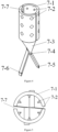
- the jaw part 7 is an enveloping-type jaw structure comprising 18 rivets 7-2 in total located on the inner wall of the semi-cylindrical jaw 7-1, which plays a fixed anti-skid role and can limit the left, right and up, down movement of the degradable occluder 8 during use.
- the two semi-cylindrical jaws 7-1 combine to form an enveloping uniform-teeth jaw, the inner wall of the enveloping uniform-teeth jaw is cylindrical that is capable to cooperate well with a fusion ball of the degradable occluder 8.
- the enveloping-type structure has large contact area and is not easy to pinch and damage the product;
- the integral connector 7-3 is the integral transition part that connects the first connecting foot 7-5, the second connecting foot 7-6 and the semi-cylindrical jaw 7-1, a first shaft hole 7-4 is provided at the connection between the integral connector 7-3 and the connecting foot, the third rotating shaft 6-7 is connected to the other end of the connecting tendon 6 through the first shaft hole 7-4 on the two integral connectors 7-3, so that the jaw can open and close;
- a reserved gap 7-7 is provided between the two semi-cylindrical jaws 7-1, so that the jaw can clamp the product (fusion ball) and can adapt to the specifications and models of products (fusion ball) in a certain size range, that is it can cooperate with a plurality of fusion balls of similar specifications;
- the degradable polymer material has certain elasticity, and the inner wall of the enveloping uniform-teeth jaw uses four-pyramid short-barb structure which can just make the poly
- the jaw part 7 is an alligator tooth jaw structure
- the two jaws form an alligator tooth jaw
- the alligator tooth jaw is composed of two curved walls 7-10 and crocodile teeth 7-8 on the curved wall 7-10
- the head end of the alligator tooth jaw is a top hole 7-9 with a circular opening
- the top hole 7-9 transitions smoothly with the curved wall 7-10, which make it not easily scratch the fusion ball, and can transition smoothly with the increase of force to make the clamping tighter, and has a certain margin, which can adapt to a plurality of fusion balls of similar specifications.
- Crocodile teeth 7-8 surround both sides of the top hole 7-9, the curved wall 7-10 plays the role of fixing the tail end of the fusion ball (there is a boss at the connection between the tail end and the net).
- the top hole 7-9 can clamp the tail part of the fusion ball in the hole, and the crocodile teeth 7-8 act on the tail end of the fusion ball to fix and prevent displacement.
- the third rotating shaft 6-7 passes through the second shaft hole 7-11 in the middle of the two jaw bars and is connected to the other end of the connecting tendon 6, the opening and closing movement is realized by the rotation of the third rotating shaft 6-7.
- the third connecting foot 7-12 and the fourth connecting foot 7-13 are connected to the connecting foot of the connecting tendon 6 of the conveying device, and can carry out long-distance transmission movement through the push handle 1.
- Crocodile teeth 7-8 are at the head end, which can firmly fix the tail part of the fusion ball (the connecting part with the occluder network), and can be locked left and right to prevent product displacement, making it more firm in the conveying process and not easy to shift and pull off.
Landscapes
- Health & Medical Sciences (AREA)
- Surgery (AREA)
- Life Sciences & Earth Sciences (AREA)
- Medical Informatics (AREA)
- Animal Behavior & Ethology (AREA)
- Engineering & Computer Science (AREA)
- Biomedical Technology (AREA)
- Heart & Thoracic Surgery (AREA)
- Veterinary Medicine (AREA)
- Molecular Biology (AREA)
- Nuclear Medicine, Radiotherapy & Molecular Imaging (AREA)
- General Health & Medical Sciences (AREA)
- Public Health (AREA)
- Cardiology (AREA)
- Reproductive Health (AREA)
- Vascular Medicine (AREA)
- Surgical Instruments (AREA)
- Wire Processing (AREA)
- Ropes Or Cables (AREA)
Claims (6)
- Système de serrage et de transport de type enveloppant en extrémité de tête, comprenant une partie mâchoire (7) et une partie poussante,dans lequel la partie poussante comprend une poignée de poussée (1), un câble d'acier de poussée (2), une tige âme (3), un fil d'ajustement, un chargeur de fil de tirage (5), et un câble de liaison (6) ;une extrémité de la poignée de poussée (1) est reliée de façon fixe à une extrémité du câble d'acier de poussée (2), l'extérieur du câble d'acier de poussée (2) est pourvu du chargeur de fil de tirage (5) approprié pour pousser le câble d'acier de poussée (2) dans une gaine, l'intérieur de la poignée de poussée (1) est relié à une extrémité de la tige âme (3), et l'autre extrémité de la tige âme (3) pénètre à l'intérieur du câble d'acier de poussée (2) et est reliée au câble de liaison (6), et le câble de liaison (6) est relié à la partie mâchoire (7) appropriée pour serrer et relâcher un obturateur dégradable (8),caractérisé en ce que la partie mâchoire (7) comprend deux barres de mâchoire, les positions médianes des deux barres de mâchoire sont reliées de façon mobile par l'intermédiaire d'une tige rotative (6-7), une extrémité de chacune des deux barres de mâchoire est pourvue d'un pied de liaison, respectivement, deux pieds de liaison d'une extrémité de chacune des deux barres de mâchoire sont reliés de façon flexible aux deux pieds de liaison des câbles de liaison (6) par l'intermédiaire d'une tige rotative supplémentaire (6-8), l'autre extrémité de chacune des deux barres de mâchoire est pourvue d'une mâchoire, respectivement ; lorsque les deux pieds de liaison d'une extrémité de chacune des deux barres de mâchoire entrent en rotation l'un relativement à l'autre autour de la tige rotative (6-7), les deux mâchoires de l'autre extrémité de chacune des deux barres de mâchoire entrent également en rotation l'une relativement l'autre, ainsi serrant l'obturateur dégradable (8) ; lorsque les deux pieds de liaison d'une extrémité de chacune des deux barres de mâchoire entrent en rotation de façon opposée l'un à l'autre autour de la tige rotative (6-7), les deux barres de mâchoire de l'autre extrémité de chacune des deux barres de mâchoire entrent également en rotation de façon opposée l'une à l'autre, ainsi relâchant l'obturateur dégradable (8),dans lequel la partie mâchoire (7) est une structure de mâchoire de type enveloppant, les deux mâchoires sont deux mâchoires semi-cylindriques (7-1) combinées pour former une mâchoire enveloppante à dents uniformes, la paroi intérieure de la mâchoire enveloppante à dents uniformes est une structure cylindrique qui est capable de coopérer avec une bille de fusion de l'obturateur dégradable (8), une pluralité de rivets (7-2) pour empêcher l'obturateur dégradable (8) d'entrer en mouvement vers la gauche et la droite ou vers le haut et le bas sont uniformément distribués sur la paroi intérieure de chaque mâchoire semi-cylindrique (7-1) ; la barre de mâchoire comprend la mâchoire semi-cylindrique (7-1), une pièce de liaison monobloc (7-3), et le pied de liaison, la pièce de liaison monobloc (7-3) est la partie de transition monobloc qui relie le pied de liaison et la mâchoire semi-cylindrique (7-1) sur les barres de mâchoire, un premier trou de tige (7-4) est prévu au niveau de la liaison entre la pièce de liaison monobloc (7-3) et le pied de liaison sur la barre de mâchoire, la tige rotative (6-7) est reliée à l'autre extrémité du câble de liaison (6) par l'intermédiaire du premier trou de tige (7-4) sur les deux pièces de liaison monoblocs (7-3) ; un espace inversé (7-7) est prévu entre les deux mâchoires semi-cylindriques (7-1) ; oula partie mâchoire (7) est une structure de mâchoires à dents de crocodile, deux mâchoires forment des mâchoires à dents de crocodile, les mâchoires à dents de crocodile sont constituées de deux parois incurvées (7-10) et de dents de crocodile (7-8) sur les parois incurvées (7-10), l'extrémité de tête des mâchoires à dents de crocodile est un trou supérieur (7-9) avec une ouverture circulaire, la transition entre le trou supérieur (7-9) et la paroi incurvée (7-10) est homogène, les dents de crocodile (7-8) entourent les deux côtés du trou supérieur (7-9), les positions médianes des deux barres de mâchoire sont pourvues d'un deuxième trou de tige (7-11), la tige rotative (6-7) est reliée à l'autre extrémité du câble de liaison (6) par l'intermédiaire du deuxième trou de tige (7-11) dans le milieu des deux barres de mâchoire.
- Système de serrage et de transport de type enveloppant en extrémité de tête selon la revendication 1, dans lequel l'autre extrémité de la tige âme (3) est reliée à deux pieds de liaison du câble de liaison (6) par l'intermédiaire d'une tige rotative additionnelle (6-6), l'autre extrémité du câble d'acier de poussée (2) est reliée de façon fixe à une extrémité du câble de liaison (6), l'autre extrémité du câble de liaison (6) est reliée à la partie mâchoire (7) par l'intermédiaire de la tige rotative (6-7).
- Système de serrage et de transport de type enveloppant en extrémité de tête selon la revendication 1 ou 2, dans lequel le fil d'ajustement prévu sur l'extérieur du câble d'acier de poussée (2) est prévu dans le chargeur de fil de tirage (5).
- Système de serrage et de transport de type enveloppant en extrémité de tête selon la revendication 3, dans lequel deux extrémités du fil d'ajustement sont une autre extrémité (9) du fil d'ajustement et une extrémité (4) du fil d'ajustement respectivement, l'autre extrémité (9) du fil d'ajustement est fixée sur la poignée de poussée (1) ; lorsque le câble d'acier de poussée (2) est prévu dans la gaine par l'intermédiaire du chargeur de fil de tirage (5), une extrémité (4) du fil d'ajustement entre dans la gaine par l'intermédiaire du chargeur de fil de tirage (5) et est reliée à l'obturateur dégradable (8) par l'intermédiaire de la partie mâchoire (7), et l'une extrémité (4) du fil d'ajustement passe à travers la partie mâchoire (7), la gaine, et le chargeur de fil de tirage (5) en séquence, et retourne à la poignée de poussée (1).
- Système de serrage et de transport de type enveloppant en extrémité de tête selon la revendication 2, dans lequel le câble de liaison (6) comprend un corps de câble de liaison (6-5), un cinquième pied de liaison (6-2), et un sixième pied de liaison (6-3) ;
dans lequel un trou central pour que la tige âme (3) passe à travers est prévu dans le corps de câble de liaison (6-5), les deux côtés du corps de câble de liaison (6-5) sont respectivement pourvus d'un trou long (6-4) qui communique avec le trou central, une extrémité de chacun du cinquième pied de liaison (6-2) et du sixième pied de liaison (6-3) est respectivement agencée sur les deux côtés du corps de câble de liaison (6-5), et est reliée aux deux pieds de liaison de la partie mâchoire (7) par l'intermédiaire de la tige rotative supplémentaire (6-8), une extrémité de chacun du cinquième pied de liaison (6-2) et du sixième pied de liaison (6-3) passe respectivement à travers les trous longs (6-4) sur les deux côtés du corps de câble de liaison (6-5), et est reliée à l'autre extrémité de la tige âme (3) dans le trou central du corps de câble de liaison (6-5) par l'intermédiaire de la tige rotative additionnelle (6-6), l'autre extrémité du câble de liaison (6) est pourvue d'un troisième trou de tige (6-1), le troisième trou de tige (6-1) du câble de liaison (6) est relié à la partie mâchoire (7) par l'intermédiaire de la tige rotative (6-7). - Système de serrage et de transport de type enveloppant en extrémité de tête selon la revendication 1, dans lequel la poignée de poussée (1) comprend un bracelet (1-4), une tête poussante (1-3), un câble poussant (1-2), un tendeur à vis (1-5), une tringle de liaison (1-7), et un bloc de poussée-tirage (1-6),
dans lequel une extrémité du bracelet (1-4) est reliée à une extrémité de la tringle de liaison (1-7), une extrémité opposée de la tringle de liaison (1-7) est pourvue d'une tête filetée ouverte (1-1), le milieu de la tringle de liaison (1-7) est pourvu d'une rainure ouverte, un bloc de poussée-tirage (1-6) qui est capable de coulisser sur la tringle de liaison (1-7) est emmanché sur la tringle de liaison (1-7), une extrémité de la tige âme (3) est reliée de façon fixe à la tête poussante (1-3) par l'intermédiaire de la tête filetée ouverte (1-1), la tête poussante (1-3) est fixée sur le câble poussant (1-2), le câble poussant (1-2) est prévu dans la rainure ouverte, l'extérieur du câble poussant (1-2) est relié au bloc de poussée-tirage (1-6) emmanché sur la tringle de liaison (1-7), le tendeur à vis (1-5), qui force la tête filetée ouverte (1-1) à serrer la tige âme (3), est emmanché sur l'extérieur de la tête filetée ouverte (1-1), une extrémité du câble d'acier de poussée (2) est reliée à la tête filetée ouverte (1-1).
Applications Claiming Priority (2)
| Application Number | Priority Date | Filing Date | Title |
|---|---|---|---|
| CN202010546781.XA CN111658026B (zh) | 2020-06-16 | 2020-06-16 | 头端环抱式夹紧输送系统 |
| PCT/CN2021/089249 WO2021253980A1 (fr) | 2020-06-16 | 2021-04-23 | Système de serrage et de transport de type à enveloppe de tête de ligne |
Publications (3)
| Publication Number | Publication Date |
|---|---|
| EP4005501A1 EP4005501A1 (fr) | 2022-06-01 |
| EP4005501A4 EP4005501A4 (fr) | 2022-11-16 |
| EP4005501B1 true EP4005501B1 (fr) | 2024-01-24 |
Family
ID=72387831
Family Applications (1)
| Application Number | Title | Priority Date | Filing Date |
|---|---|---|---|
| EP21825366.4A Active EP4005501B1 (fr) | 2020-06-16 | 2021-04-23 | Système de serrage et de transport de type à enveloppe de tête de ligne |
Country Status (5)
| Country | Link |
|---|---|
| EP (1) | EP4005501B1 (fr) |
| CN (1) | CN111658026B (fr) |
| ES (1) | ES2979309T3 (fr) |
| PL (1) | PL4005501T3 (fr) |
| WO (1) | WO2021253980A1 (fr) |
Families Citing this family (3)
| Publication number | Priority date | Publication date | Assignee | Title |
|---|---|---|---|---|
| CN111658026B (zh) * | 2020-06-16 | 2024-11-29 | 上海形状记忆合金材料有限公司 | 头端环抱式夹紧输送系统 |
| CN113413243B (zh) * | 2021-06-22 | 2025-12-09 | 上海形状记忆合金材料有限公司 | 一种可锁紧的无铆生物心房分流装置 |
| CN114027915B (zh) * | 2021-08-26 | 2023-09-08 | 上海形状记忆合金材料有限公司 | 一种带成型线保护的心血管封堵器输送装置 |
Family Cites Families (12)
| Publication number | Priority date | Publication date | Assignee | Title |
|---|---|---|---|---|
| DE29500381U1 (de) * | 1994-08-24 | 1995-07-20 | Schneidt, Bernhard, Ing.(grad.), 63571 Gelnhausen | Vorrichtung zum Verschließen eines Ductus, insbesondere des Ductus arteriosus |
| US7955354B2 (en) * | 2005-11-14 | 2011-06-07 | Occlutech Gmbh | Occlusion device and surgical instrument and method for its implantation/explantation |
| EP2609872B2 (fr) * | 2009-05-06 | 2019-01-02 | Occlutech Holding AG | Dispositif médical pour fournir un implant médical |
| US8956389B2 (en) * | 2009-06-22 | 2015-02-17 | W. L. Gore & Associates, Inc. | Sealing device and delivery system |
| CN201578327U (zh) * | 2009-12-30 | 2010-09-15 | 杭州康基医疗器械有限公司 | 直视微创无损小抓钳 |
| CN201905938U (zh) * | 2010-11-30 | 2011-07-27 | 上海长海医院 | 经导管微创介入术用输送及回收装置 |
| CN103690202B (zh) * | 2013-12-30 | 2016-04-20 | 先健科技(深圳)有限公司 | 植入体的输送装置与植入医疗器械 |
| CN106618664B (zh) * | 2016-12-06 | 2023-04-14 | 上海心玮医疗科技股份有限公司 | 一种左心耳封堵器输送系统 |
| CN109498074A (zh) * | 2019-01-04 | 2019-03-22 | 上海形状记忆合金材料有限公司 | 完全可降解封堵器专用推送装置及其与封堵器连接的方法 |
| CN110876633B (zh) * | 2019-12-03 | 2024-06-14 | 江苏博朗森思医疗器械有限公司 | 一种可降解封堵器的专用输送器 |
| CN111658026B (zh) * | 2020-06-16 | 2024-11-29 | 上海形状记忆合金材料有限公司 | 头端环抱式夹紧输送系统 |
| CN212939808U (zh) * | 2020-06-16 | 2021-04-13 | 上海形状记忆合金材料有限公司 | 一种头端环抱式夹紧输送系统 |
-
2020
- 2020-06-16 CN CN202010546781.XA patent/CN111658026B/zh active Active
-
2021
- 2021-04-23 PL PL21825366.4T patent/PL4005501T3/pl unknown
- 2021-04-23 WO PCT/CN2021/089249 patent/WO2021253980A1/fr not_active Ceased
- 2021-04-23 ES ES21825366T patent/ES2979309T3/es active Active
- 2021-04-23 EP EP21825366.4A patent/EP4005501B1/fr active Active
Also Published As
| Publication number | Publication date |
|---|---|
| EP4005501A1 (fr) | 2022-06-01 |
| CN111658026A (zh) | 2020-09-15 |
| CN111658026B (zh) | 2024-11-29 |
| WO2021253980A1 (fr) | 2021-12-23 |
| ES2979309T3 (es) | 2024-09-25 |
| PL4005501T3 (pl) | 2024-06-10 |
| EP4005501A4 (fr) | 2022-11-16 |
Similar Documents
| Publication | Publication Date | Title |
|---|---|---|
| US20230108042A1 (en) | Hemostatic clipping devices and methods | |
| EP4005501A1 (fr) | Système de serrage et de transport de type à enveloppe de tête de ligne | |
| CN102727276B (zh) | 一种组织止血夹持装置 | |
| CN207871026U (zh) | 一种操作稳定的介入心脏瓣膜可回收输送系统 | |
| CN109953779B (zh) | 夹合装置及固定组织的系统 | |
| EP3247443B1 (fr) | Cathéter de guidage avec mécanismes de guidage | |
| EP2630919B1 (fr) | Dispositif de délivrance intravasculaire, système et implant | |
| WO2007054014A1 (fr) | Dispositif de pose servant a la mise en place d'une endoprothese auto-expansible | |
| CN212939808U (zh) | 一种头端环抱式夹紧输送系统 | |
| US11844911B2 (en) | Vascular access disassembling needle device and method | |
| EP3903744B1 (fr) | Cathéter de pose et dispositif de pose de valve artificielle | |
| WO2013060832A1 (fr) | Combinaison d'appareils pour la connexion d'organes creux (anastomose) | |
| US20210161694A1 (en) | Delivery device | |
| CN202699219U (zh) | 一种组织止血夹持装置 | |
| CN114680992A (zh) | 止血夹用的夹头组件及止血夹 | |
| CN110876633B (zh) | 一种可降解封堵器的专用输送器 | |
| CN109984778A (zh) | 医用缝合装置及缝合系统 | |
| CN215018331U (zh) | 止血夹用的夹头组件及止血夹 | |
| CN217548112U (zh) | 一种用于心房分流器的输送系统 | |
| CN219229967U (zh) | 一种基于电控的心房分流器输送系统 | |
| US20210322192A1 (en) | Medical Device Implantation Apparatus | |
| CN213310062U (zh) | 一种旋转夹子装置 | |
| WO2021129631A1 (fr) | Dispositif de pose et de libération d'endoprothèse et système de pose et de libération d'endoprothèse | |
| CN114869360A (zh) | 一种用于心房分流器的输送系统 | |
| CN120227200A (zh) | 一种具有离合组件的瓣膜修复系统 |
Legal Events
| Date | Code | Title | Description |
|---|---|---|---|
| STAA | Information on the status of an ep patent application or granted ep patent |
Free format text: STATUS: THE INTERNATIONAL PUBLICATION HAS BEEN MADE |
|
| PUAI | Public reference made under article 153(3) epc to a published international application that has entered the european phase |
Free format text: ORIGINAL CODE: 0009012 |
|
| STAA | Information on the status of an ep patent application or granted ep patent |
Free format text: STATUS: REQUEST FOR EXAMINATION WAS MADE |
|
| 17P | Request for examination filed |
Effective date: 20220225 |
|
| AK | Designated contracting states |
Kind code of ref document: A1 Designated state(s): AL AT BE BG CH CY CZ DE DK EE ES FI FR GB GR HR HU IE IS IT LI LT LU LV MC MK MT NL NO PL PT RO RS SE SI SK SM TR |
|
| A4 | Supplementary search report drawn up and despatched |
Effective date: 20221019 |
|
| RIC1 | Information provided on ipc code assigned before grant |
Ipc: A61B 17/12 20060101ALN20221013BHEP Ipc: A61B 17/00 20060101AFI20221013BHEP |
|
| RIC1 | Information provided on ipc code assigned before grant |
Ipc: A61B 17/12 20060101ALN20230628BHEP Ipc: A61B 17/00 20060101AFI20230628BHEP |
|
| GRAP | Despatch of communication of intention to grant a patent |
Free format text: ORIGINAL CODE: EPIDOSNIGR1 |
|
| STAA | Information on the status of an ep patent application or granted ep patent |
Free format text: STATUS: GRANT OF PATENT IS INTENDED |
|
| RIC1 | Information provided on ipc code assigned before grant |
Ipc: A61B 17/12 20060101ALN20230720BHEP Ipc: A61B 17/00 20060101AFI20230720BHEP |
|
| DAV | Request for validation of the european patent (deleted) | ||
| DAX | Request for extension of the european patent (deleted) | ||
| INTG | Intention to grant announced |
Effective date: 20230808 |
|
| GRAS | Grant fee paid |
Free format text: ORIGINAL CODE: EPIDOSNIGR3 |
|
| GRAA | (expected) grant |
Free format text: ORIGINAL CODE: 0009210 |
|
| STAA | Information on the status of an ep patent application or granted ep patent |
Free format text: STATUS: THE PATENT HAS BEEN GRANTED |
|
| AK | Designated contracting states |
Kind code of ref document: B1 Designated state(s): AL AT BE BG CH CY CZ DE DK EE ES FI FR GB GR HR HU IE IS IT LI LT LU LV MC MK MT NL NO PL PT RO RS SE SI SK SM TR |
|
| REG | Reference to a national code |
Ref country code: GB Ref legal event code: FG4D |
|
| REG | Reference to a national code |
Ref country code: CH Ref legal event code: EP |
|
| REG | Reference to a national code |
Ref country code: IE Ref legal event code: FG4D |
|
| REG | Reference to a national code |
Ref country code: DE Ref legal event code: R096 Ref document number: 602021008798 Country of ref document: DE |
|
| REG | Reference to a national code |
Ref country code: NL Ref legal event code: FP |
|
| REG | Reference to a national code |
Ref country code: LT Ref legal event code: MG9D |
|
| PG25 | Lapsed in a contracting state [announced via postgrant information from national office to epo] |
Ref country code: IS Free format text: LAPSE BECAUSE OF FAILURE TO SUBMIT A TRANSLATION OF THE DESCRIPTION OR TO PAY THE FEE WITHIN THE PRESCRIBED TIME-LIMIT Effective date: 20240524 |
|
| PG25 | Lapsed in a contracting state [announced via postgrant information from national office to epo] |
Ref country code: LT Free format text: LAPSE BECAUSE OF FAILURE TO SUBMIT A TRANSLATION OF THE DESCRIPTION OR TO PAY THE FEE WITHIN THE PRESCRIBED TIME-LIMIT Effective date: 20240124 |
|
| PG25 | Lapsed in a contracting state [announced via postgrant information from national office to epo] |
Ref country code: GR Free format text: LAPSE BECAUSE OF FAILURE TO SUBMIT A TRANSLATION OF THE DESCRIPTION OR TO PAY THE FEE WITHIN THE PRESCRIBED TIME-LIMIT Effective date: 20240425 |
|
| REG | Reference to a national code |
Ref country code: AT Ref legal event code: MK05 Ref document number: 1651543 Country of ref document: AT Kind code of ref document: T Effective date: 20240124 |
|
| PG25 | Lapsed in a contracting state [announced via postgrant information from national office to epo] |
Ref country code: HR Free format text: LAPSE BECAUSE OF FAILURE TO SUBMIT A TRANSLATION OF THE DESCRIPTION OR TO PAY THE FEE WITHIN THE PRESCRIBED TIME-LIMIT Effective date: 20240124 Ref country code: RS Free format text: LAPSE BECAUSE OF FAILURE TO SUBMIT A TRANSLATION OF THE DESCRIPTION OR TO PAY THE FEE WITHIN THE PRESCRIBED TIME-LIMIT Effective date: 20240424 |
|
| PG25 | Lapsed in a contracting state [announced via postgrant information from national office to epo] |
Ref country code: AT Free format text: LAPSE BECAUSE OF FAILURE TO SUBMIT A TRANSLATION OF THE DESCRIPTION OR TO PAY THE FEE WITHIN THE PRESCRIBED TIME-LIMIT Effective date: 20240124 |
|
| PG25 | Lapsed in a contracting state [announced via postgrant information from national office to epo] |
Ref country code: RS Free format text: LAPSE BECAUSE OF FAILURE TO SUBMIT A TRANSLATION OF THE DESCRIPTION OR TO PAY THE FEE WITHIN THE PRESCRIBED TIME-LIMIT Effective date: 20240424 Ref country code: NO Free format text: LAPSE BECAUSE OF FAILURE TO SUBMIT A TRANSLATION OF THE DESCRIPTION OR TO PAY THE FEE WITHIN THE PRESCRIBED TIME-LIMIT Effective date: 20240424 Ref country code: LT Free format text: LAPSE BECAUSE OF FAILURE TO SUBMIT A TRANSLATION OF THE DESCRIPTION OR TO PAY THE FEE WITHIN THE PRESCRIBED TIME-LIMIT Effective date: 20240124 Ref country code: IS Free format text: LAPSE BECAUSE OF FAILURE TO SUBMIT A TRANSLATION OF THE DESCRIPTION OR TO PAY THE FEE WITHIN THE PRESCRIBED TIME-LIMIT Effective date: 20240524 Ref country code: HR Free format text: LAPSE BECAUSE OF FAILURE TO SUBMIT A TRANSLATION OF THE DESCRIPTION OR TO PAY THE FEE WITHIN THE PRESCRIBED TIME-LIMIT Effective date: 20240124 Ref country code: GR Free format text: LAPSE BECAUSE OF FAILURE TO SUBMIT A TRANSLATION OF THE DESCRIPTION OR TO PAY THE FEE WITHIN THE PRESCRIBED TIME-LIMIT Effective date: 20240425 Ref country code: FI Free format text: LAPSE BECAUSE OF FAILURE TO SUBMIT A TRANSLATION OF THE DESCRIPTION OR TO PAY THE FEE WITHIN THE PRESCRIBED TIME-LIMIT Effective date: 20240124 Ref country code: BG Free format text: LAPSE BECAUSE OF FAILURE TO SUBMIT A TRANSLATION OF THE DESCRIPTION OR TO PAY THE FEE WITHIN THE PRESCRIBED TIME-LIMIT Effective date: 20240124 Ref country code: AT Free format text: LAPSE BECAUSE OF FAILURE TO SUBMIT A TRANSLATION OF THE DESCRIPTION OR TO PAY THE FEE WITHIN THE PRESCRIBED TIME-LIMIT Effective date: 20240124 |
|
| PG25 | Lapsed in a contracting state [announced via postgrant information from national office to epo] |
Ref country code: PT Free format text: LAPSE BECAUSE OF FAILURE TO SUBMIT A TRANSLATION OF THE DESCRIPTION OR TO PAY THE FEE WITHIN THE PRESCRIBED TIME-LIMIT Effective date: 20240524 |
|
| PG25 | Lapsed in a contracting state [announced via postgrant information from national office to epo] |
Ref country code: SE Free format text: LAPSE BECAUSE OF FAILURE TO SUBMIT A TRANSLATION OF THE DESCRIPTION OR TO PAY THE FEE WITHIN THE PRESCRIBED TIME-LIMIT Effective date: 20240124 Ref country code: PT Free format text: LAPSE BECAUSE OF FAILURE TO SUBMIT A TRANSLATION OF THE DESCRIPTION OR TO PAY THE FEE WITHIN THE PRESCRIBED TIME-LIMIT Effective date: 20240524 Ref country code: LV Free format text: LAPSE BECAUSE OF FAILURE TO SUBMIT A TRANSLATION OF THE DESCRIPTION OR TO PAY THE FEE WITHIN THE PRESCRIBED TIME-LIMIT Effective date: 20240124 |
|
| REG | Reference to a national code |
Ref country code: ES Ref legal event code: FG2A Ref document number: 2979309 Country of ref document: ES Kind code of ref document: T3 Effective date: 20240925 |
|
| PG25 | Lapsed in a contracting state [announced via postgrant information from national office to epo] |
Ref country code: DK Free format text: LAPSE BECAUSE OF FAILURE TO SUBMIT A TRANSLATION OF THE DESCRIPTION OR TO PAY THE FEE WITHIN THE PRESCRIBED TIME-LIMIT Effective date: 20240124 |
|
| PG25 | Lapsed in a contracting state [announced via postgrant information from national office to epo] |
Ref country code: SM Free format text: LAPSE BECAUSE OF FAILURE TO SUBMIT A TRANSLATION OF THE DESCRIPTION OR TO PAY THE FEE WITHIN THE PRESCRIBED TIME-LIMIT Effective date: 20240124 |
|
| PG25 | Lapsed in a contracting state [announced via postgrant information from national office to epo] |
Ref country code: CZ Free format text: LAPSE BECAUSE OF FAILURE TO SUBMIT A TRANSLATION OF THE DESCRIPTION OR TO PAY THE FEE WITHIN THE PRESCRIBED TIME-LIMIT Effective date: 20240124 Ref country code: EE Free format text: LAPSE BECAUSE OF FAILURE TO SUBMIT A TRANSLATION OF THE DESCRIPTION OR TO PAY THE FEE WITHIN THE PRESCRIBED TIME-LIMIT Effective date: 20240124 |
|
| REG | Reference to a national code |
Ref country code: DE Ref legal event code: R097 Ref document number: 602021008798 Country of ref document: DE |
|
| PG25 | Lapsed in a contracting state [announced via postgrant information from national office to epo] |
Ref country code: SK Free format text: LAPSE BECAUSE OF FAILURE TO SUBMIT A TRANSLATION OF THE DESCRIPTION OR TO PAY THE FEE WITHIN THE PRESCRIBED TIME-LIMIT Effective date: 20240124 |
|
| PG25 | Lapsed in a contracting state [announced via postgrant information from national office to epo] |
Ref country code: SM Free format text: LAPSE BECAUSE OF FAILURE TO SUBMIT A TRANSLATION OF THE DESCRIPTION OR TO PAY THE FEE WITHIN THE PRESCRIBED TIME-LIMIT Effective date: 20240124 Ref country code: SK Free format text: LAPSE BECAUSE OF FAILURE TO SUBMIT A TRANSLATION OF THE DESCRIPTION OR TO PAY THE FEE WITHIN THE PRESCRIBED TIME-LIMIT Effective date: 20240124 Ref country code: EE Free format text: LAPSE BECAUSE OF FAILURE TO SUBMIT A TRANSLATION OF THE DESCRIPTION OR TO PAY THE FEE WITHIN THE PRESCRIBED TIME-LIMIT Effective date: 20240124 Ref country code: DK Free format text: LAPSE BECAUSE OF FAILURE TO SUBMIT A TRANSLATION OF THE DESCRIPTION OR TO PAY THE FEE WITHIN THE PRESCRIBED TIME-LIMIT Effective date: 20240124 Ref country code: CZ Free format text: LAPSE BECAUSE OF FAILURE TO SUBMIT A TRANSLATION OF THE DESCRIPTION OR TO PAY THE FEE WITHIN THE PRESCRIBED TIME-LIMIT Effective date: 20240124 |
|
| PG25 | Lapsed in a contracting state [announced via postgrant information from national office to epo] |
Ref country code: MC Free format text: LAPSE BECAUSE OF FAILURE TO SUBMIT A TRANSLATION OF THE DESCRIPTION OR TO PAY THE FEE WITHIN THE PRESCRIBED TIME-LIMIT Effective date: 20240124 |
|
| PG25 | Lapsed in a contracting state [announced via postgrant information from national office to epo] |
Ref country code: MC Free format text: LAPSE BECAUSE OF FAILURE TO SUBMIT A TRANSLATION OF THE DESCRIPTION OR TO PAY THE FEE WITHIN THE PRESCRIBED TIME-LIMIT Effective date: 20240124 |
|
| PLBE | No opposition filed within time limit |
Free format text: ORIGINAL CODE: 0009261 |
|
| STAA | Information on the status of an ep patent application or granted ep patent |
Free format text: STATUS: NO OPPOSITION FILED WITHIN TIME LIMIT |
|
| PG25 | Lapsed in a contracting state [announced via postgrant information from national office to epo] |
Ref country code: LU Free format text: LAPSE BECAUSE OF NON-PAYMENT OF DUE FEES Effective date: 20240423 |
|
| REG | Reference to a national code |
Ref country code: BE Ref legal event code: MM Effective date: 20240430 |
|
| PG25 | Lapsed in a contracting state [announced via postgrant information from national office to epo] |
Ref country code: LU Free format text: LAPSE BECAUSE OF NON-PAYMENT OF DUE FEES Effective date: 20240423 |
|
| 26N | No opposition filed |
Effective date: 20241025 |
|
| PG25 | Lapsed in a contracting state [announced via postgrant information from national office to epo] |
Ref country code: BE Free format text: LAPSE BECAUSE OF NON-PAYMENT OF DUE FEES Effective date: 20240430 |
|
| PG25 | Lapsed in a contracting state [announced via postgrant information from national office to epo] |
Ref country code: BE Free format text: LAPSE BECAUSE OF NON-PAYMENT OF DUE FEES Effective date: 20240430 |
|
| PGFP | Annual fee paid to national office [announced via postgrant information from national office to epo] |
Ref country code: NL Payment date: 20250325 Year of fee payment: 5 |
|
| PGFP | Annual fee paid to national office [announced via postgrant information from national office to epo] |
Ref country code: IE Payment date: 20250320 Year of fee payment: 5 |
|
| PG25 | Lapsed in a contracting state [announced via postgrant information from national office to epo] |
Ref country code: SI Free format text: LAPSE BECAUSE OF FAILURE TO SUBMIT A TRANSLATION OF THE DESCRIPTION OR TO PAY THE FEE WITHIN THE PRESCRIBED TIME-LIMIT Effective date: 20240124 |
|
| PGFP | Annual fee paid to national office [announced via postgrant information from national office to epo] |
Ref country code: PL Payment date: 20250319 Year of fee payment: 5 |
|
| PGFP | Annual fee paid to national office [announced via postgrant information from national office to epo] |
Ref country code: DE Payment date: 20250411 Year of fee payment: 5 |
|
| PGFP | Annual fee paid to national office [announced via postgrant information from national office to epo] |
Ref country code: GB Payment date: 20250417 Year of fee payment: 5 Ref country code: ES Payment date: 20250512 Year of fee payment: 5 |
|
| PGFP | Annual fee paid to national office [announced via postgrant information from national office to epo] |
Ref country code: IT Payment date: 20250409 Year of fee payment: 5 |
|
| PGFP | Annual fee paid to national office [announced via postgrant information from national office to epo] |
Ref country code: FR Payment date: 20250429 Year of fee payment: 5 |
|
| PGFP | Annual fee paid to national office [announced via postgrant information from national office to epo] |
Ref country code: CH Payment date: 20250501 Year of fee payment: 5 |
|
| PGFP | Annual fee paid to national office [announced via postgrant information from national office to epo] |
Ref country code: TR Payment date: 20250409 Year of fee payment: 5 |
|
| PG25 | Lapsed in a contracting state [announced via postgrant information from national office to epo] |
Ref country code: CY Free format text: LAPSE BECAUSE OF FAILURE TO SUBMIT A TRANSLATION OF THE DESCRIPTION OR TO PAY THE FEE WITHIN THE PRESCRIBED TIME-LIMIT; INVALID AB INITIO Effective date: 20210423 |
|
| PG25 | Lapsed in a contracting state [announced via postgrant information from national office to epo] |
Ref country code: RO Free format text: LAPSE BECAUSE OF FAILURE TO SUBMIT A TRANSLATION OF THE DESCRIPTION OR TO PAY THE FEE WITHIN THE PRESCRIBED TIME-LIMIT Effective date: 20240124 |
|
| PG25 | Lapsed in a contracting state [announced via postgrant information from national office to epo] |
Ref country code: HU Free format text: LAPSE BECAUSE OF FAILURE TO SUBMIT A TRANSLATION OF THE DESCRIPTION OR TO PAY THE FEE WITHIN THE PRESCRIBED TIME-LIMIT; INVALID AB INITIO Effective date: 20210423 |