EP4005699A1 - Vorrichtung zur generativen fertigung - Google Patents
Vorrichtung zur generativen fertigung Download PDFInfo
- Publication number
- EP4005699A1 EP4005699A1 EP20845034.6A EP20845034A EP4005699A1 EP 4005699 A1 EP4005699 A1 EP 4005699A1 EP 20845034 A EP20845034 A EP 20845034A EP 4005699 A1 EP4005699 A1 EP 4005699A1
- Authority
- EP
- European Patent Office
- Prior art keywords
- fabricated object
- region
- fabrication
- abnormally
- solidified
- Prior art date
- Legal status (The legal status is an assumption and is not a legal conclusion. Google has not performed a legal analysis and makes no representation as to the accuracy of the status listed.)
- Withdrawn
Links
Images


Classifications
-
- B—PERFORMING OPERATIONS; TRANSPORTING
- B22—CASTING; POWDER METALLURGY
- B22F—WORKING METALLIC POWDER; MANUFACTURE OF ARTICLES FROM METALLIC POWDER; MAKING METALLIC POWDER; APPARATUS OR DEVICES SPECIALLY ADAPTED FOR METALLIC POWDER
- B22F12/00—Apparatus or devices specially adapted for additive manufacturing; Auxiliary means for additive manufacturing; Combinations of additive manufacturing apparatus or devices with other processing apparatus or devices
- B22F12/90—Means for process control, e.g. cameras or sensors
-
- B—PERFORMING OPERATIONS; TRANSPORTING
- B22—CASTING; POWDER METALLURGY
- B22F—WORKING METALLIC POWDER; MANUFACTURE OF ARTICLES FROM METALLIC POWDER; MAKING METALLIC POWDER; APPARATUS OR DEVICES SPECIALLY ADAPTED FOR METALLIC POWDER
- B22F10/00—Additive manufacturing of workpieces or articles from metallic powder
- B22F10/20—Direct sintering or melting
- B22F10/28—Powder bed fusion, e.g. selective laser melting [SLM] or electron beam melting [EBM]
-
- B—PERFORMING OPERATIONS; TRANSPORTING
- B22—CASTING; POWDER METALLURGY
- B22F—WORKING METALLIC POWDER; MANUFACTURE OF ARTICLES FROM METALLIC POWDER; MAKING METALLIC POWDER; APPARATUS OR DEVICES SPECIALLY ADAPTED FOR METALLIC POWDER
- B22F10/00—Additive manufacturing of workpieces or articles from metallic powder
- B22F10/30—Process control
- B22F10/31—Calibration of process steps or apparatus settings, e.g. before or during manufacturing
-
- B—PERFORMING OPERATIONS; TRANSPORTING
- B22—CASTING; POWDER METALLURGY
- B22F—WORKING METALLIC POWDER; MANUFACTURE OF ARTICLES FROM METALLIC POWDER; MAKING METALLIC POWDER; APPARATUS OR DEVICES SPECIALLY ADAPTED FOR METALLIC POWDER
- B22F10/00—Additive manufacturing of workpieces or articles from metallic powder
- B22F10/30—Process control
- B22F10/38—Process control to achieve specific product aspects, e.g. surface smoothness, density, porosity or hollow structures
-
- B—PERFORMING OPERATIONS; TRANSPORTING
- B22—CASTING; POWDER METALLURGY
- B22F—WORKING METALLIC POWDER; MANUFACTURE OF ARTICLES FROM METALLIC POWDER; MAKING METALLIC POWDER; APPARATUS OR DEVICES SPECIALLY ADAPTED FOR METALLIC POWDER
- B22F10/00—Additive manufacturing of workpieces or articles from metallic powder
- B22F10/50—Treatment of workpieces or articles during build-up, e.g. treatments applied to fused layers during build-up
-
- B—PERFORMING OPERATIONS; TRANSPORTING
- B22—CASTING; POWDER METALLURGY
- B22F—WORKING METALLIC POWDER; MANUFACTURE OF ARTICLES FROM METALLIC POWDER; MAKING METALLIC POWDER; APPARATUS OR DEVICES SPECIALLY ADAPTED FOR METALLIC POWDER
- B22F10/00—Additive manufacturing of workpieces or articles from metallic powder
- B22F10/80—Data acquisition or data processing
- B22F10/85—Data acquisition or data processing for controlling or regulating additive manufacturing processes
-
- B—PERFORMING OPERATIONS; TRANSPORTING
- B22—CASTING; POWDER METALLURGY
- B22F—WORKING METALLIC POWDER; MANUFACTURE OF ARTICLES FROM METALLIC POWDER; MAKING METALLIC POWDER; APPARATUS OR DEVICES SPECIALLY ADAPTED FOR METALLIC POWDER
- B22F12/00—Apparatus or devices specially adapted for additive manufacturing; Auxiliary means for additive manufacturing; Combinations of additive manufacturing apparatus or devices with other processing apparatus or devices
- B22F12/40—Radiation means
- B22F12/41—Radiation means characterised by the type, e.g. laser or electron beam
-
- B—PERFORMING OPERATIONS; TRANSPORTING
- B29—WORKING OF PLASTICS; WORKING OF SUBSTANCES IN A PLASTIC STATE IN GENERAL
- B29C—SHAPING OR JOINING OF PLASTICS; SHAPING OF MATERIAL IN A PLASTIC STATE, NOT OTHERWISE PROVIDED FOR; AFTER-TREATMENT OF THE SHAPED PRODUCTS, e.g. REPAIRING
- B29C64/00—Additive manufacturing, i.e. manufacturing of three-dimensional [3D] objects by additive deposition, additive agglomeration or additive layering, e.g. by 3D printing, stereolithography or selective laser sintering
- B29C64/10—Processes of additive manufacturing
- B29C64/141—Processes of additive manufacturing using only solid materials
- B29C64/153—Processes of additive manufacturing using only solid materials using layers of powder being selectively joined, e.g. by selective laser sintering or melting
-
- B—PERFORMING OPERATIONS; TRANSPORTING
- B29—WORKING OF PLASTICS; WORKING OF SUBSTANCES IN A PLASTIC STATE IN GENERAL
- B29C—SHAPING OR JOINING OF PLASTICS; SHAPING OF MATERIAL IN A PLASTIC STATE, NOT OTHERWISE PROVIDED FOR; AFTER-TREATMENT OF THE SHAPED PRODUCTS, e.g. REPAIRING
- B29C64/00—Additive manufacturing, i.e. manufacturing of three-dimensional [3D] objects by additive deposition, additive agglomeration or additive layering, e.g. by 3D printing, stereolithography or selective laser sintering
- B29C64/30—Auxiliary operations or equipment
- B29C64/386—Data acquisition or data processing for additive manufacturing
- B29C64/393—Data acquisition or data processing for additive manufacturing for controlling or regulating additive manufacturing processes
-
- B—PERFORMING OPERATIONS; TRANSPORTING
- B22—CASTING; POWDER METALLURGY
- B22F—WORKING METALLIC POWDER; MANUFACTURE OF ARTICLES FROM METALLIC POWDER; MAKING METALLIC POWDER; APPARATUS OR DEVICES SPECIALLY ADAPTED FOR METALLIC POWDER
- B22F2999/00—Aspects linked to processes or compositions used in powder metallurgy
-
- B—PERFORMING OPERATIONS; TRANSPORTING
- B33—ADDITIVE MANUFACTURING TECHNOLOGY
- B33Y—ADDITIVE MANUFACTURING, i.e. MANUFACTURING OF THREE-DIMENSIONAL [3D] OBJECTS BY ADDITIVE DEPOSITION, ADDITIVE AGGLOMERATION OR ADDITIVE LAYERING, e.g. BY 3D PRINTING, STEREOLITHOGRAPHY OR SELECTIVE LASER SINTERING
- B33Y10/00—Processes of additive manufacturing
-
- B—PERFORMING OPERATIONS; TRANSPORTING
- B33—ADDITIVE MANUFACTURING TECHNOLOGY
- B33Y—ADDITIVE MANUFACTURING, i.e. MANUFACTURING OF THREE-DIMENSIONAL [3D] OBJECTS BY ADDITIVE DEPOSITION, ADDITIVE AGGLOMERATION OR ADDITIVE LAYERING, e.g. BY 3D PRINTING, STEREOLITHOGRAPHY OR SELECTIVE LASER SINTERING
- B33Y30/00—Apparatus for additive manufacturing; Details thereof or accessories therefor
-
- B—PERFORMING OPERATIONS; TRANSPORTING
- B33—ADDITIVE MANUFACTURING TECHNOLOGY
- B33Y—ADDITIVE MANUFACTURING, i.e. MANUFACTURING OF THREE-DIMENSIONAL [3D] OBJECTS BY ADDITIVE DEPOSITION, ADDITIVE AGGLOMERATION OR ADDITIVE LAYERING, e.g. BY 3D PRINTING, STEREOLITHOGRAPHY OR SELECTIVE LASER SINTERING
- B33Y50/00—Data acquisition or data processing for additive manufacturing
- B33Y50/02—Data acquisition or data processing for additive manufacturing for controlling or regulating additive manufacturing processes
-
- Y—GENERAL TAGGING OF NEW TECHNOLOGICAL DEVELOPMENTS; GENERAL TAGGING OF CROSS-SECTIONAL TECHNOLOGIES SPANNING OVER SEVERAL SECTIONS OF THE IPC; TECHNICAL SUBJECTS COVERED BY FORMER USPC CROSS-REFERENCE ART COLLECTIONS [XRACs] AND DIGESTS
- Y02—TECHNOLOGIES OR APPLICATIONS FOR MITIGATION OR ADAPTATION AGAINST CLIMATE CHANGE
- Y02P—CLIMATE CHANGE MITIGATION TECHNOLOGIES IN THE PRODUCTION OR PROCESSING OF GOODS
- Y02P10/00—Technologies related to metal processing
- Y02P10/25—Process efficiency
Definitions
- the present application relates to an AM apparatus.
- the present application claims priority under the Paris Convention to Japanese Patent Application No. 2019-136255 filed on July 24, 2019 .
- the entire disclosure of Japanese Patent Application No. 2019-136255 including the specification, the claims, the drawings, and the abstract is incorporated herein by reference in its entirety.
- each layer of the three-dimensional object is fabricated by, toward the metal powder deposited all over a surface, irradiating a portion thereof to be fabricated with a laser beam or an electron beam serving as a heat source, and melting and solidifying or sintering the metal powder.
- AM Additive Manufacturing
- a desired three-dimensional object can be fabricated by repeating such a process.
- An AM apparatus using the metal powder as the material gradually forms each layer of the fabricated object by causing the beam to scan layer by layer. Therefore, as the size of the fabricated object increases, the time taken for the fabrication also increases. Then, one conceivable measure for reducing the fabrication time is to increase the irradiation energy and the scanning speed of the beam. However, increasing the irradiation energy of the beam is easily accompanied by an excessive increase in the temperature of the surface of the metal powder layer to thus facilitate the occurrence of fume and spatter. The occurrence of fume and spatter during the fabrication can cloud the window or the lens of the beam irradiation system, thereby leading to a reduction in the energy with which the metal powder is irradiated and thus resulting in incomplete melting.
- one of the objects of the present invention is to allow the AM apparatus to reduce the risk of the abnormal stop of the AM apparatus. Further, one of the objects of the present invention is to provide a technique that allows the fabrication to be retried from halfway through without opening the fabrication chamber even when the AM apparatus is stopped halfway through.
- an AM apparatus for manufacturing a fabricated object includes a detector configured to detect a shape of an upper surface of the fabricated object in the middle of fabrication, a determination device configured to determine which applies to a state of the upper surface of the fabricated object, (1) an unmelted region, (2) an abnormally solidified region, or (3) a normally solidified region based on data acquired from the detector, and a repair device configured to repair the region determined to be the abnormally solidified region by the determination device.
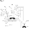
- FIG. 1 schematically illustrates an AM apparatus for manufacturing a fabricated object according to one embodiment.
- an AM apparatus 100 includes a fabrication chamber 102.
- a buildup chamber 106 is attached to a bottom surface 104 of the fabrication chamber 102.
- a lift table 108 is installed in the buildup chamber 106.
- the lift table 108 is movable in the vertical direction (a z direction) by a driving mechanism 110.
- the driving mechanism 110 may be, for example, a pneumatic or hydraulic driving mechanism or may be a driving mechanism including a motor and a ball screw.
- An inlet and an outlet for introducing and discharging protective gas into and out of the fabrication chamber 102 may be provided, although they are not illustrated.
- an XY stage 112 is disposed on the lift table 108 as illustrated in Fig. 1 .
- the XY stage 112 is a stage movable in two directions (an x direction and a y direction) in parallel with the plane of the lift table 108.
- a base plate 114 for supporting a material of the fabricated object is disposed on the XY stage 112.
- a material supply mechanism 150 for supplying the material of the fabricated object is disposed above the buildup chamber 106 in the fabrication chamber 102.
- the material supply mechanism 150 includes a storage container 154 for holding powder 152 used as the material of the fabricated object, such as metal powder, and a movement mechanism 160 for moving the storage container 154.
- the storage container 154 includes an opening 156 for discharging the material powder 152 onto the base plate 114.
- the opening 156 can be, for example, a linear opening 156 longer than one side of the base plate 114.
- the material powder 152 can be supplied to the entire surface of the base plate 114 by configuring the movement mechanism 160 so as to move in a range longer than the other side of the base plate 114 in a direction perpendicular to the line of the opening 156.
- the storage container 154 includes a valve 158 for controlling the opening/closing of the opening 156.
- the material supply mechanism 150 may include a blade 159 for leveling out the material powder 152 supplied from the storage container 154.
- each of the storage containers 154 may be used to hold a different material or may be used to hold the material powder 152 that is the same material but has a different particle diameter.
- the AM apparatus 100 includes a laser light source 170, and a scanning mechanism 174, which guides a laser 172 emitted from the laser light source 170 toward the material powder 152 on the base plate 114, as illustrated in Fig. 1 .
- the AM apparatus 100 illustrated in Fig. 1 includes an adjustment device 171 for adjusting the intensity of the beam to be emitted. This adjustment device 171 can be configured to adjust the power of electricity to be supplied to the laser light source or the electron beam source.
- the AM apparatus 100 illustrated in Fig. 1 includes a beam shaper 173 for adjusting the shape and the profile of the beam to be emitted.
- the laser light source 170, the adjustment device 171, the beam shaper 173, and the scanning mechanism 174 are disposed in the fabrication chamber 102, but all or a part of them may be disposed outside the fabrication chamber 102.
- the scanning mechanism 174 can be formed by an arbitrary optical system, and is configured to be able to irradiate an arbitrary position of a fabrication plane (a focus plane) on the base plate 114 with the laser 172.
- the AM apparatus 100 includes a molten pool monitor 175 for monitoring a molten pool formed by the irradiation of the material powder 152 with the beam.
- the molten pool monitor 175 can include a non-contact type sensor, and may be realized by, for example, employing a method that irradiates the molten pool while superimposing a laser for the measurement on the optical axis of the laser for melting the metal with use of a monochromatic radiation thermometer that works with a measurement wavelength of approximately 650 nm, and receives reflected light on a detection element such as silicon.
- the molten pool monitor 175 may be configured to be able to measure the temperature, the shape of the liquid surface, the depth, and/or the like of the molten pool.
- the laser for the measurement uses a wavelength different from the wavelength of the laser for the melting. Temperature data measured by the molten pool monitor 175 is transmitted to a control device 200. Any molten pool monitor including a known molten pool monitor 175 can be used as the molten pool monitor 175.
- an electron beam source may be used instead of the laser light source 170.
- the scanning mechanism 174 includes a magnet or the like, and is configured to be able to irradiate an arbitrary position of the fabrication plane on the base plate 114 with an electron beam.
- the AM apparatus 100 includes a detector 250 for detecting the shape of the fabricated object.
- the detector 250 can be a 3D camera.
- the detector 250 can three-dimensionally measure the shape of the surface of the fabricated object M1 in the middle of the fabrication.
- the AM apparatus 100 includes a beam monitor 252 for detecting the energy of the emitted beam.
- the beam monitor 252 can be, for example, a light receiving element or a Faraday cup disposed in the route of the beam.
- the beam monitor 252 may be disposed at a position that a reflected beam or a beam transmitted from the route of the beam reaches.
- the AM apparatus 100 includes a thermometer 254 for detecting the temperature of the wall surface of the fabrication chamber 102.
- the AM apparatus 100 includes a concentration meter 255 that measures the concentration of oxygen in the fabrication chamber 102.
- the AM apparatus 100 includes a driving torque monitor (not illustrated) for detecting the driving torque of a movement mechanism of the blade 159 for leveling out the material powder 152 supplied from the storage container 154.
- the AM apparatus 100 includes a vibration meter 258 for detecting a vibration.
- the vibration meter 258 can be disposed at, for example, the support rod or the wall surface of the fabrication chamber 102, an arbitrary location in the AM apparatus 100 such as the scanning mechanism 174, the floor on which the AM apparatus 100 is set up, or the base used to set up the AM apparatus, although the vibration meter 258 can be disposed at any location.
- the AM apparatus 100 includes the control device 200.
- the control device 200 is configured to control the operations of various kinds of operation mechanisms of the AM apparatus 100, such as the above-described driving mechanism 110, movement mechanism 160, laser light source 170, adjustment device 171, beam shaper 173, scanning mechanism 174, and valve 158 of the opening 156. Further, the control device 200 is configured to receive measured values from various kinds of measurement devices, such as the detector 250, the beam monitor 252, the thermometer 254, the driving torque motor, and the vibration meter 258.
- the control device 200 can be formed by a general computer or a dedicated computer.
- the procedure therefor is as outlined below.
- three-dimensional data D1 of a fabrication target is input to the control device 200.
- the control device 200 generates slice data for the fabrication based on the input three-dimensional data D1 of the fabricated object.
- the control device 200 generates execution data including fabrication conditions and the recipe.
- the fabrication conditions and the recipe include, for example, beam conditions, beam scanning conditions, and layering conditions.
- the beam conditions include voltage conditions, a laser output, and the like of the laser light source 170 in the case where the laser is used, or include a beam voltage, a beam current, and the like in the case where the electron beam is used.
- the beam scanning conditions include a scanning pattern, a scanning route, a scanning speed, a scanning interval, and the like.
- Examples of the scanning pattern include a pattern when the beam scans in one direction, a pattern when the beam scans in reciprocating directions, a pattern when the beam scans zigzag, and a pattern when the beam moves transversely while drawing a small circle.
- the scanning route determines, for example, in what order the beam scans.
- the layering conditions include, for example, a material type, an average particle diameter of the powder material, a particle shape, a particle size distribution, a layering thickness (a thickness in which the material powder is deposited all over the surface at the time of the fabrication), and a fabrication thickness coefficient (a ratio between the layering thickness and the thickness of the actually manufactured fabricated object).
- a part of the above-described fabrication conditions and recipe may be generated and changed according to the input three-dimensional data of the fabricated object or may be determined in advance independently of the input three-dimensional data of the fabricated object.
- the material powder 152 of the fabricated object such as metal powder, is loaded into the storage container 154.
- the lift table 108 of the buildup chamber 106 is moved to an upper position, by which the surface of the base plate 114 is adjusted so as to be positioned on the focus plane of the laser 172.
- the valve 158 of the opening 156 of the storage container 154 is opened and the storage container 154 is moved, and then the material powder 152 is evenly supplied onto the base plate 114.
- the material supply mechanism 150 is controlled by the control device 200 so as to supply the material powder 152 onto the focus plane by an amount corresponding to one layer of the fabricated object (corresponding to the above-described "layering thickness").
- a fabricated object M1 corresponding to one layer is created by emitting the laser 172 from the laser light source 170, irradiating a predetermined range of the focus plane with the laser 172 by the scanning mechanism 174, and melting and sintering the material powder at a predetermined position.
- the irradiation position of the laser 172 may be changed by also moving the XY stage 112 disposed on the lift table 108 if necessary.
- the lift table 108 of the buildup chamber 106 is lowered by a distance corresponding to one layer.
- the material powder 152 is supplied onto the focus plane by the material supply mechanism 150 by an amount corresponding to one layer of the fabricated object again.
- the fabricated object M1 corresponding to one layer is created by causing the laser 172 to scan on the focus plane by the scanning mechanism 174 and melting and sintering the material powder 152 at a predetermined position.
- the targeted fabricated object M1 can be entirely created from the powder 152 by repeating these operations.
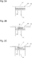
- Fig. 2 is a flowchart illustrating a procedure of a fabrication method according to one embodiment.
- the material powder is supplied to a predetermined position of the AM apparatus 100 and is irradiated with the beam to be melted and solidified in a predetermined region, the melted and solidified surface is imaged by the detector 250.
- the detector 250 is the 3D camera capable of three-dimensionally measuring the shape of the surface of the fabricated object M1 in the middle of the fabrication. Therefore, whether the material powder can be appropriately melted and solidified can be determined by observing the shape of the surface of the fabricated object M1 in the middle of the fabrication with use of the detector 250.
- Figs. 3 each schematically illustrate a cross-sectional shape of the fabricated object in the middle of the fabrication.
- Fig. 3A illustrates a state before the material powder 152 is irradiated with the beam after being supplied.
- a region surrounded by a broken line in Fig. 3A indicates a selected region A1 to be irradiated with the beam.
- Fig. 3B schematically illustrates a state in which the material powder 152 is normally melted and solidified after being irradiated with the beam from the state illustrated in Fig. 3A . Due to the melting and the solidification of the material powder 152, the height of the selected region A1 is lowered compared to the other regions, and the surface is located at a predetermined height if the material powder 152 is normally melted and solidified. Since the detector 250 can three-dimensionally measure the shape of the surface of the fabricated object M1 as described above, whether the material powder 152 is normally melted and solidified in the selected region A1 can be determined by detecting the height and the evenness of the surface of the fabricated object M1.
- Fig. 3C schematically illustrates an example of a state in which the material powder 152 is not normally melted and solidified after being irradiated with the beam from the state illustrated in Fig. 3A .
- a recessed portion is generated on a part of the upper surface of the fabricated object M1. If an abnormality has occurred in the fabricated object, the abnormal portion is repaired as indicated by the flowchart illustrated in Fig. 2 .
- the abnormal portion can be repaired by, for example, filling the recessed portion by directed energy deposition (DED).
- DED directed energy deposition
- the AM apparatus 100 includes a DED nozzle 270, and can repair the recessed portion on the surface of the fabricated object M1 within the fabrication chamber 102 with use of the DED nozzle 270.
- the DED nozzle 270 can be configured to, for example, allow the material powder and a laser to be supplied from the nozzle to a predetermined position, and the material to be directly supplied, melted, and solidified at the predetermined position. Any DED nozzle, such as a known DED nozzle, can be used as the DED nozzle 270.
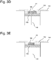
- Fig. 3D schematically illustrates an example of the state in which the material powder 152 is not normally melted and solidified after being irradiated with the beam from the state illustrated in Fig. 3A .
- a protrusion portion is generated on a part of the upper surface of the fabricated object M1. If an abnormality has occurred in the fabricated object, the abnormal portion is repaired as indicated by the flowchart illustrated in Fig. 2 .
- the abnormal portion can be repaired by, for example, removing the protrusion portion by laser ablation.
- the AM apparatus 100 includes an ablation nozzle 272, and can remove the protrusion portion on the surface of the fabricated object M1 within the fabrication chamber 102 with use of a laser emitted from the ablation nozzle 272.
- the ablation nozzle 272 can be configured to, for example, allow a pulse laser to be supplied from the nozzle to a predetermined position, and the solid at the predetermined position to be melted and evaporated, thereby removing it. Any ablation nozzle, such as a known ablation nozzle, can be used as the ablation nozzle 272.
- Fig. 3E schematically illustrates an example of the state in which the material powder 152 is not normally melted and solidified after being irradiated with the beam from the state illustrated in Fig. 3A .
- the material powder 152 partially fails to be melted and solidified in the selected region A1, and remains as the material powder 152. If an abnormality has occurred in the fabricated object, the abnormal portion is repaired as indicated by the flowchart illustrated in Fig. 2 .
- the abnormal portion can be repaired by, for example, melting and solidifying the unmelted region with use of the beam from the laser light source 170.
- the unmelted region, the abnormally solidified region, or the normally solidified region can be determined by using the detector 250. Basically, this determination can be made based on the height of the imaged fabricated object M1.
- the surface of the fabricated object M1 is determined to be the normally solidified region if the height of the fabricated object M1 matches an even height expected when the material powder 152 is normally melted and solidified, or is determined to include the abnormally solidified region if the height of the fabricated object M1 is partially raised or lowered.
- the surface of the fabricated object M1 can be determined to be the unmelted region if the selected region A1 after the irradiation with the beam includes a region having the same height as a non-selected region.
- the AM apparatus 100 can be configured in such a manner that the control device 200 makes the determination about which applies to the surface of the fabricated object M1, the unmelted region, the abnormally solidified region, or the normally solidified region. Further, since the positions of the unmelted region and the abnormally solidified region can be located with use of the detector 250, the unmelted region and the abnormally solidified region can be appropriately repaired by causing the DED nozzle 270, the ablation nozzle 272, the scanning mechanism 174, or the like to scan by the control device 200.
- an abnormality in the fabrication is detected by observing the shape of the fabricated object surface of the fabricated object M1 with use of the detector 250 again. If there is an abnormal portion, the abnormal portion is repaired as described above. If there is no abnormal portion, the fabrication proceeds to a procedure for forming a next layer.
- the detector 250 can three-dimensionally measure the shape of the surface of the fabricated object M1 as described above, whether the material powder 152 is normally melted and solidified in the selected region A1 can be determined by detecting the height and the evenness of the surface of the fabricated object M1. Further, even when there is an abnormal portion in the fabricated object, the abnormal portion can be repaired within the fabrication chamber 102 as described above. Therefore, even when an abnormality has occurred during the fabrication, the abnormal portion can be repaired without opening the fabrication chamber 102. Since the abnormal portion during the fabrication can be repaired within the fabrication chamber, the present configuration can reduce the risk that the AM apparatus is abnormally stopped due to a malfunction of the mechanism for supplying the powder material according to an abnormality in the fabrication.
- the present configuration allows the recovery work to be performed without opening the fabrication chamber 102 by repairing the abnormal portion within the fabrication chamber, thereby being able to reduce the risk that the time and the material are wastefully consumed.
- the AM apparatus 100 includes the various kinds of sensors, such as the molten pool monitor 175, the beam monitor 252, the thermometer 254, the concentration meter 255, the driving torque monitor, and the vibration meter 258. Therefore, the AM apparatus 100 can detect the state of the AM apparatus 100 when an abnormality has occurred in the fabricated object, and, further, record the state of the AM apparatus 100 when the abnormality has occurred in the fabricated object. Analyzing the data acquired from the various kinds of sensors when the abnormality has occurred in the fabricated object is useful to identify the cause for the occurrence of the abnormality.
- sensors such as the molten pool monitor 175, the beam monitor 252, the thermometer 254, the concentration meter 255, the driving torque monitor, and the vibration meter 258. Therefore, the AM apparatus 100 can detect the state of the AM apparatus 100 when an abnormality has occurred in the fabricated object, and, further, record the state of the AM apparatus 100 when the abnormality has occurred in the fabricated object. Analyzing the data acquired from the various kinds of sensors when the abnormality has occurred in the
- the acquired data may be utilized to, for example, set a threshold value for determining an error to the various kinds of sensors based on the state of the AM apparatus when the abnormality has occurred in the fabricated object, and stop the operation of the AM apparatus before an abnormality has actually occurred in the fabricated object and conduct maintenance of the AM apparatus 100 or replace a component of the AM apparatus 100.
- an AM apparatus for manufacturing a fabricated object includes a detector configured to detect a shape of an upper surface of the fabricated object in the middle of fabrication, a determination device configured to determine which applies to a state of the upper surface of the fabricated object, (1) an unmelted region, (2) an abnormally solidified region, or (3) a normally solidified region based on data acquired from the detector, and a repair device configured to repair the region determined to be the abnormally solidified region by the determination device.
- the detector is a 3D camera.
- the determination device is configured to make the determination based on a height of the upper surface of the fabricated object.
- the repair device includes a laser ablation nozzle and/or a directed energy deposition nozzle.
- a method for manufacturing a fabricated object by an AM technique includes the steps of detecting an abnormality in an AM apparatus and interrupting fabrication processing, observing a state of an upper surface of the fabricated object fabricated until the fabrication processing is interrupted, comparing observed data and data for fabrication according to the AM technique and determining which applies to the upper surface of the fabricated object, (1) an unmelted region, (2) an abnormally solidified region, or (3) a normally solidified region, repairing the abnormally solidified region in a case where the upper surface of the fabricated object is determined to include the abnormally solidified region, observing the state of the upper surface of the repaired fabricated object, and restarting the fabrication processing in a case where the upper surface of the repaired fabricated object does not include the unmelted region and the abnormally solidified region.
Landscapes
- Engineering & Computer Science (AREA)
- Chemical & Material Sciences (AREA)
- Materials Engineering (AREA)
- Manufacturing & Machinery (AREA)
- Physics & Mathematics (AREA)
- Automation & Control Theory (AREA)
- Optics & Photonics (AREA)
- Plasma & Fusion (AREA)
- Analytical Chemistry (AREA)
- Mechanical Engineering (AREA)
- Health & Medical Sciences (AREA)
- General Health & Medical Sciences (AREA)
- Toxicology (AREA)
- Powder Metallurgy (AREA)
Applications Claiming Priority (2)
| Application Number | Priority Date | Filing Date | Title |
|---|---|---|---|
| JP2019136225A JP2021020319A (ja) | 2019-07-24 | 2019-07-24 | Am装置 |
| PCT/JP2020/021955 WO2021014779A1 (ja) | 2019-07-24 | 2020-06-03 | Am装置 |
Publications (1)
| Publication Number | Publication Date |
|---|---|
| EP4005699A1 true EP4005699A1 (de) | 2022-06-01 |
Family
ID=74193750
Family Applications (1)
| Application Number | Title | Priority Date | Filing Date |
|---|---|---|---|
| EP20845034.6A Withdrawn EP4005699A1 (de) | 2019-07-24 | 2020-06-03 | Vorrichtung zur generativen fertigung |
Country Status (5)
| Country | Link |
|---|---|
| US (1) | US20220258248A1 (de) |
| EP (1) | EP4005699A1 (de) |
| JP (1) | JP2021020319A (de) |
| CN (1) | CN114144270A (de) |
| WO (1) | WO2021014779A1 (de) |
Families Citing this family (3)
| Publication number | Priority date | Publication date | Assignee | Title |
|---|---|---|---|---|
| JP7096311B2 (ja) * | 2020-11-12 | 2022-07-05 | 株式会社ソディック | 積層造形装置及び積層造形物の製造方法 |
| JP7743321B2 (ja) * | 2022-01-28 | 2025-09-24 | 三菱重工業株式会社 | 三次元積層造形装置の評価システム、及び、三次元積層造形装置の評価方法 |
| WO2024180614A1 (ja) * | 2023-02-27 | 2024-09-06 | 技術研究組合次世代3D積層造形技術総合開発機構 | 3次元積層造形システムおよび3次元積層造形方法 |
Family Cites Families (13)
| Publication number | Priority date | Publication date | Assignee | Title |
|---|---|---|---|---|
| JP3599059B2 (ja) | 2003-02-25 | 2004-12-08 | 松下電工株式会社 | 三次元形状造形物の製造方法及びその装置 |
| WO2013098054A1 (en) * | 2011-12-28 | 2013-07-04 | Arcam Ab | Method and apparatus for detecting defects in freeform fabrication |
| US9931785B2 (en) | 2013-03-15 | 2018-04-03 | 3D Systems, Inc. | Chute for laser sintering systems |
| US20150064047A1 (en) * | 2013-08-28 | 2015-03-05 | Elwha Llc | Systems and methods for additive manufacturing of three dimensional structures |
| CN107428080A (zh) * | 2015-03-12 | 2017-12-01 | 株式会社尼康 | 三维造型物制造装置及构造物的制造方法 |
| WO2017194122A1 (en) * | 2016-05-12 | 2017-11-16 | Hewlett-Packard Development Company, L P | Temperature control prior to fusion |
| CN106404795A (zh) * | 2016-10-26 | 2017-02-15 | 华中科技大学 | 一种基于红外信息的金属增材制造过程控制装置与方法 |
| CN108060417A (zh) * | 2016-11-07 | 2018-05-22 | 东台精机股份有限公司 | 粉末积层制造的检测修补装置及其方法 |
| CN114653972A (zh) * | 2017-05-10 | 2022-06-24 | 莫纳什大学 | 用于添加制造工艺的质量保证和控制的方法和系统 |
| US10710307B2 (en) * | 2017-08-11 | 2020-07-14 | Applied Materials, Inc. | Temperature control for additive manufacturing |
| WO2019111827A1 (ja) * | 2017-12-06 | 2019-06-13 | 日立金属株式会社 | 金属積層造形物の製造方法及び金属積層造形物 |
| JP2019104981A (ja) * | 2017-12-14 | 2019-06-27 | キヤノン株式会社 | 三次元造形装置および三次元造形物の製造方法 |
| JP2019136255A (ja) | 2018-02-08 | 2019-08-22 | 東芝ライフスタイル株式会社 | 自走式電気掃除機 |
-
2019
- 2019-07-24 JP JP2019136225A patent/JP2021020319A/ja active Pending
-
2020
- 2020-06-03 EP EP20845034.6A patent/EP4005699A1/de not_active Withdrawn
- 2020-06-03 CN CN202080052981.8A patent/CN114144270A/zh active Pending
- 2020-06-03 US US17/625,981 patent/US20220258248A1/en not_active Abandoned
- 2020-06-03 WO PCT/JP2020/021955 patent/WO2021014779A1/ja not_active Ceased
Also Published As
| Publication number | Publication date |
|---|---|
| WO2021014779A1 (ja) | 2021-01-28 |
| JP2021020319A (ja) | 2021-02-18 |
| US20220258248A1 (en) | 2022-08-18 |
| CN114144270A (zh) | 2022-03-04 |
Similar Documents
| Publication | Publication Date | Title |
|---|---|---|
| US11344952B2 (en) | Three-dimensional additive manufacturing device, three-dimensional additive manufacturing method, and three-dimensional additive manufactured product | |
| US20220355550A1 (en) | Apparatus for manufacturing three dimensional shaped object, and method for manufacturing structure | |
| JP6189820B2 (ja) | 放射線検出装置を用いた三次元ワークピースの製造装置及び製造方法 | |
| EP4005699A1 (de) | Vorrichtung zur generativen fertigung | |
| CN111867754B (zh) | 用于使多束照射系统对准的方法 | |
| EP3210713A1 (de) | Überwachung der laserleistungs in der generativen fertigung | |
| US20170274599A1 (en) | Additive manufacturing apparatus and additive manufacturing method | |
| US12059744B2 (en) | Laser machining device | |
| EP3412383A1 (de) | Vorrichtung zur generativen fertigung eines produkts mit einer kalibriervorrichtung und verfahren zur kalibrierung solch einer vorrichtung | |
| CN114450584A (zh) | 层叠造形系统 | |
| EP3708341A1 (de) | Vorrichtung zur generativen fertigung dreidimensionaler objekte | |
| US20220234285A1 (en) | Am apparatus | |
| JP2020104524A (ja) | 三次元造形物製造装置 | |
| US11571750B2 (en) | Lamination molding apparatus and method for producing three-dimensional molded object | |
| EP4101564A1 (de) | Verfahren und vorrichtung zur überwachung des betriebs einer pulverbettfusionsmaschine zur generativen fertigung | |
| KR101164523B1 (ko) | 레이저 빔 프로파일러를 구비하는 레이저 가공장치 | |
| US12459039B2 (en) | AM apparatus for manufacturing a fabricated object and method for testing an irradiation position of a beam in the AM apparatus | |
| WO2022218451A1 (en) | Method for monitoring and control of pulsed laser micro-processing and apparatus for carrying out this method |
Legal Events
| Date | Code | Title | Description |
|---|---|---|---|
| STAA | Information on the status of an ep patent application or granted ep patent |
Free format text: STATUS: THE INTERNATIONAL PUBLICATION HAS BEEN MADE |
|
| PUAI | Public reference made under article 153(3) epc to a published international application that has entered the european phase |
Free format text: ORIGINAL CODE: 0009012 |
|
| STAA | Information on the status of an ep patent application or granted ep patent |
Free format text: STATUS: REQUEST FOR EXAMINATION WAS MADE |
|
| 17P | Request for examination filed |
Effective date: 20220124 |
|
| AK | Designated contracting states |
Kind code of ref document: A1 Designated state(s): AL AT BE BG CH CY CZ DE DK EE ES FI FR GB GR HR HU IE IS IT LI LT LU LV MC MK MT NL NO PL PT RO RS SE SI SK SM TR |
|
| DAV | Request for validation of the european patent (deleted) | ||
| DAX | Request for extension of the european patent (deleted) | ||
| STAA | Information on the status of an ep patent application or granted ep patent |
Free format text: STATUS: THE APPLICATION HAS BEEN WITHDRAWN |
|
| 18W | Application withdrawn |
Effective date: 20230420 |