EP4005732B1 - Tragbares werkzeug zur oberflächenbehandlung mit absaugung, das mit einem von einem handschuh getragenen ansatzstück versehen ist, und sein anwendungsverfahren - Google Patents
Tragbares werkzeug zur oberflächenbehandlung mit absaugung, das mit einem von einem handschuh getragenen ansatzstück versehen ist, und sein anwendungsverfahren Download PDFInfo
- Publication number
- EP4005732B1 EP4005732B1 EP21210639.7A EP21210639A EP4005732B1 EP 4005732 B1 EP4005732 B1 EP 4005732B1 EP 21210639 A EP21210639 A EP 21210639A EP 4005732 B1 EP4005732 B1 EP 4005732B1
- Authority
- EP
- European Patent Office
- Prior art keywords
- treatment
- glove
- suction
- block
- container
- Prior art date
- Legal status (The legal status is an assumption and is not a legal conclusion. Google has not performed a legal analysis and makes no representation as to the accuracy of the status listed.)
- Active
Links
Images


Classifications
-
- B—PERFORMING OPERATIONS; TRANSPORTING
- B24—GRINDING; POLISHING
- B24D—TOOLS FOR GRINDING, BUFFING OR SHARPENING
- B24D15/00—Hand tools or other devices for non-rotary grinding, polishing, or stropping
- B24D15/02—Hand tools or other devices for non-rotary grinding, polishing, or stropping rigid; with rigidly-supported operative surface
-
- B—PERFORMING OPERATIONS; TRANSPORTING
- B24—GRINDING; POLISHING
- B24B—MACHINES, DEVICES, OR PROCESSES FOR GRINDING OR POLISHING; DRESSING OR CONDITIONING OF ABRADING SURFACES; FEEDING OF GRINDING, POLISHING, OR LAPPING AGENTS
- B24B55/00—Safety devices for grinding or polishing machines; Accessories fitted to grinding or polishing machines for keeping tools or parts of the machine in good working condition
- B24B55/06—Dust extraction equipment on grinding or polishing machines
- B24B55/10—Dust extraction equipment on grinding or polishing machines specially designed for portable grinding machines, e.g. hand-guided
-
- B—PERFORMING OPERATIONS; TRANSPORTING
- B24—GRINDING; POLISHING
- B24D—TOOLS FOR GRINDING, BUFFING OR SHARPENING
- B24D15/00—Hand tools or other devices for non-rotary grinding, polishing, or stropping
- B24D15/04—Hand tools or other devices for non-rotary grinding, polishing, or stropping resilient; with resiliently-mounted operative surface
- B24D15/045—Glove-shaped abrasive devices
Definitions
- the invention relates to a portable tool for treating surfaces of any type, in particular sanding or sanding, comprising a suction system.
- This tool is particularly suitable for preparing the metal surfaces of aircraft.
- Sanding is light sanding to eliminate defects and machining marks on said part or part of the aircraft structure while preserving a correct surface condition.
- the present invention aims to provide a tool making it possible to overcome these drawbacks and to allow access to confined areas or as close as possible to obstacles.
- the document JPH07313410 discloses a tool for suction of dust which adheres to the leaves of plants.
- the tool comprises a suction body connected to a pipe itself connected with at least one conduit carried by a glove so that the end of the conduit is at the level of the tip of a finger carrying a brush.
- the document US 1012634 describes a vacuum cleaning tool comprising a sheath capable of receiving a user's hand, the sheath having fingers between which are recesses connected to a main pipe at the rear of the glove in connection with a suction pump adapted, branches making communication between the recesses and the main pipe.
- the invention relates to a portable suction surface treatment tool of particles characterized in that it comprises a surface treatment tip comprising a surface adapted to the desired treatment carried by a glove, the tip being in communication with a container housing a suction device through a conduit to allow the suction of particles, the tip comprising at least two bricks, a first brick fixed to the glove and a second surface treatment brick carrying the desired treatment surface, the conduit being connected to one or other of the bricks and the bricks being removably bonded.
- the suction tip of reduced size can approach as closely as possible complex shapes of a surface to be processing, varied reliefs, protruding elements such as panel fixings or other particular shapes.
- the tip is equipped with the elements necessary to carry out the desired treatment.
- the invention provides at least one of the following optional characteristics, taken individually or in combination.
- the tip includes three bricks, a first attachment brick attached to the glove, a second suction brick removably attached thereto and a third surface treatment brick, the second suction brick connected to the conduit and the third surface treatment brick carrying the surface suitable for the desired treatment.
- the tip is positioned at the end of a finger of the glove.
- the container includes means allowing removable attachment to a carrying armband.
- the container is portable over the shoulder.
- the container includes a removable filter capsule for filtering and retaining particles.
- the container includes a non-return valve to prevent vacuumed particles from returning to the conduit.
- the tool includes a set of surface treatment bricks of different shapes chosen according to the shape of the surface to be treated.
- the tip has an abrasive surface for surface treatment such as sanding or ginning.
- the present invention also relates to a method of using the surface treatment tool having at least one of the optional characteristics previous characterized in that it comprises the following steps: - choice of a surface treatment brick according to the shape of the surface to be treated; - placement of the surface treatment brick on the brick(s) already attached to the glove; - placing the glove on an operator's hand; -positioning of the container on a part of the operator's body; activation of the suction.
- the present invention is illustrated in the following by taking the example of a fuselage panel 2 of an aircraft. However, it is not limited to this application and can concern any part, part, structure of an aircraft or even another vehicle such as for example an automobile, a ship, a train or others, or even any other structure.
- the surface treatment tool 4 comprises three parts each ensuring at least one specific function: a part 6 dedicated to surface treatment, suction and guiding of the vacuumed particles called surface treatment part, a part 8 dedicated for the recovery and filtering of particles as well as for housing a suction device 10 properly said, hereinafter called filtering part 8, a part 12 ensuring the connection between the two being in the form illustrated in the form of a conduit 14.
- the conduit is hollow and made of any type of flexible material to allow the threading described below, for example in flexible plastic.
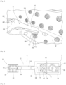
- the surface treatment part 6 must be kept in operation as close as possible to the surface to be treated as shown in the figure 1 .
- the filtering part 8 comprises a portable container 16 to house all of the systems necessary for suction, recovery and filtering of particles.
- These three parts 6, 8 and 12 can each form an independent individual element or be associated at least partially with another part to form only a single block. In the illustrated embodiment, each of the parts is independent to better ensure maintenance and portability.
- the surface treatment tool 4 as a whole is portable by a single operator as shown by the figures 1 and 3 .
- Part 6 dedicated to surface treatment comprises a removable tip 18 having a surface 20 adapted to the desired treatment with which particles are projected into the air in the vicinity of the operator hence the need to suck them up.
- the treatments requiring particle suction are varied: sanding, sanding, brushing, machining such as making mini-scratches, or any other type of treatment.
- surface 20 is an abrasive surface; In the following we use the term sanding to cover both the sanding and ginning operations.
- the surface 20 carries more or less flexible, more or less long fibers, threads, filaments or equivalents.
- the surface is provided with mini-blades or equivalent. It may also be necessary to use a tip to increase the roughness to improve the adhesion of a coating. In conclusion, the tip is equipped with the elements necessary to carry out the desired treatment.
- the tool 4 includes protective equipment in the form of a glove 22 ( figures 1 and 3 ) carrying said end piece 18.
- the end piece 18 can be in one piece, in a single block or comprise several bricks 26 as shown in Figure 5 .
- first brick fixed to the glove and a second surface treatment brick and for example a sanding brick carrying the abrasive surface.
- conduit 14 is connected to one or other of the bricks. Both bricks are removably attached to each other.
- the term removable will be understood throughout the description to mean detachable without damaging the connecting surfaces in contact.
- the removable/detachable attachment can for example be achieved by clipping, Velcro type hook and loop tape (registered trademark) or others.
- the bricks 26 are fixed to each other by light pressure and held together by interlocking with slight interference.
- the tip 18 comprises three bricks 28, 30 and 32, a first 28 fixed to the glove, called the fixing brick, a second 30, called the suction brick fixed removably to this and to a third brick 32 called surface treatment removably attached to the second suction brick 30.
- the second suction brick 30 is connected to the conduit 14 and the third brick 32 for surface treatment and for example sanding carries the surface 20 adapted to the desired treatment, in the example given an abrasive surface.
- the first and second configuration are identical with the only difference that the suction brick and the fixing brick are one in the first.
- Each brick 26 has two connecting faces opposite each other.
- the fixing brick 28 has a face 34A for connection with the glove 22 and an opposite face for connection 34B with the suction brick 30.
- the suction brick 30 has a face 30A for connection with the fixing brick 28 and an opposite face 30B for fixing with the surface treatment brick 32.
- the surface treatment brick 32 has a face 32A connecting with the suction brick 30 and a face 32B corresponding to the surface 20 adapted to the desired treatment and in the example of sanding the abrasive surface.
- the connecting face 34B of the fixing block comprises protruding parts 36 or projections of shape corresponding to cavities 38 provided opening onto the connecting face 30A of the suction block 30.
- the projections 36 and cavities 38 are interlocking with a slight interference to allow their removable attachment to each other.
- the projections 36 and cavities 38 are of parallelepiped shape with a square section but could be of a different shape, for example cylindrical with a circular section.
- the same principle is used for the connecting faces 30B and 32A allowing removable attachment between the suction brick 30 and the surface treatment brick 32. Any shape is possible as long as the bricks are removably attached to each other.
- the bricks 26 are of parallelepiped shape with a generally rectangular section.
- the surface treatment brick 32 is equipped as seen previously with what is necessary to carry out the desired surface treatment.
- the brick 32 includes an abrasive consumable 40, visible on the figures 1 and 3 , one of the faces of which constitutes the face 32B with an abrasive surface.
- the consumable 40 is glued to the other part of the brick 32 by any type of means and for example by gluing.
- the sanding brick can also form a single block made up of said consumable (or of the equipment necessary for the desired operation in the case of another type of surface treatment).
- the panels 2 on which the tool 4 operates can have complex shapes, varied reliefs, be provided with projecting elements such as fixings 41 (visible on the figure 1 ).
- the tool 4 comprises a set of surface treatment bricks 32 and in the illustrated example sanding bricks of different shapes chosen according to the shape of the surface to be treated. Due to being removably attached to another brick and in the second configuration illustrated, to the suction brick 30, the operator can change the shape of the sanding brick 32 depending on the surface to be treated.
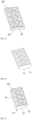
- THE figures 6 to 8 represent several shape examples. There Figure 6 illustrates a brick 32 of parallelepiped shape of rectangular section having a flat abrasive surface 20. There Figure 7 shows a brick 32 whose abrasive surface 20 is rounded in shape.
- FIG 8 illustrates a brick 32 whose section has a rectangular trapezoidal section, the large and small base being in a direction perpendicular to the connecting face 32A: thus the abrasive surface 20 is flat and inclined relative to the face 32A forming an acute angle with lateral face 42 concerned (on the side of the large base of the trapezoid).
- the pointed part 43 formed at this acute angle allows the sanding brick to reach areas that are difficult to access.
- the tool can also include several different surface treatment bricks: it can for example be equipped with a brick for producing mini-scratches, a sanding brick and a brushing brick.
- the suction brick 30 and the surface treatment brick 32 comprise at least one interior channel 44 and in the form illustrated and more particularly visible on the Figure 4 , a network of interior longitudinal 46 and transverse 48 channels 44 making it possible to guide the air sucked in from the face 32B adapted to the desired treatment and for example abrasive to the exterior conduit 14 connecting with the particle evacuation and filtering part 8 24.
- the face 32B adapted to the desired treatment comprises at least one suction opening 50 through which one or more 48 transverse channels suck in air.
- the transverse channels 48 of the surface treatment brick pass through the surface treatment brick 32 and correspond with transverse channels 48 of the suction brick 30.
- each channel 48 of both bricks is positioned so that they join and do not form more than one and the same transverse channel.
- One of the side faces 52 of the suction brick has a side opening 54 in direct communication with the exterior conduit 14.
- a portion 56 of conduit extends outwards around which the outer conduit 14 threads.
- An interior longitudinal channel 46 passes longitudinally through a part of the suction brick 30 to open into said lateral opening 54.
- One of the ends of the aligned transverse channels 48 of the surface treatment and suction bricks corresponds to the suction openings 50 and the other end communicates with the longitudinal channel 46.
- the suction openings 50 communicate with the exterior conduit 14 through the network of transverse 48 and longitudinal 46 channels of the surface treatment and suction bricks.
- the fixing brick 28 is linked in a removable manner or not with the glove 22.
- the principle used can be identical to that used for fixing with the suction brick, namely by interference interlocking. with a brick forming part of the glove or by any other type of known means.
- the tip is positioned at the end of a finger 58 of the glove 22 ( figures 1 and 3 ).
- the glove 22 is taken in its most generic meaning, namely any piece of fabric, leather or other material capable of enveloping a part of the hand which can be reduced to the strict minimum necessary for the use of the tool.
- the glove 22 comprises an envelope 60 of only one finger 58 of the hand and more particularly here the index finger and an extension 62 intended to be applied to the dorsal face of the hand carrying two wrist fixing straps of which only one 64 is visible on the Figure 3 .
- the two straps surround the wrist and attach to each other by any type of removable means. According to one embodiment, they can have different textures at one of their ends, for example loops for one and hooks for the other, of the Velcro type (Registered trademark).
- the glove can be worn by either the right or left hand.
- Particles 24 emitted such as dust, fibers or others contaminate the air ambient, aircraft parts and the working environment.
- the pollution generated on aircraft parts can be harmful for subsequent operations such as, for example, the painting of the parts. While machining, particles must therefore be removed from the surrounding environment as quickly as possible.
- the use of certain particles such as chromates may be subject to regulations and it is recommended to avoid inhaling them.
- Tool 4 and more particularly part 8 allows them to be sucked up and evacuated to a filter 67 which captures them and stores them in container 16.
- the container 16 which can have any type of shape, has in the form illustrated an overall cylindrical shape of circular section.
- the suction device 10 is housed.
- the device 10 will not be described in detail: it is presented in any type of known form and for example that of conventional portable vacuum cleaners.
- the container 16 has a suction orifice 68 through which the particles 24 are sucked in by the device 10.
- a portion 70 of conduit extends outwards around which s thread the outer conduit 14.
- a non-return valve 72 is provided inside the container 16 at the orifice 68.
- the valve 72 makes it possible to avoid the return towards the nozzle 18 and therefore towards the outside of aspirated particles 24 and particularly the particles mentioned above which it is preferable not to inhale.
- a removable filtering capsule 74 provided with filter 67 making it possible to intercept certain particles and in the aforementioned example in particular chromate particles.
- the container 16 can be dismantled or can have a cover allowing access to the interior thereof or any system allowing access to the interior of the container and being able to dismantle the capsule and /or allow maintenance of the suction device 10 or any other part.
- the capsule has a rim 76 entering into a slot 78 provided in the container 16.
- the capsule 74 is positioned between the orifice 68 and the device 10. Conventionally, an evacuation opening 80 is provided on the side opposite to the suction orifice 68, behind the suction device 10.
- the container 16 can be carried in any way by a single operator; two alternatives are illustrated. On the Figure 9 , the container 16 is carried over the shoulder 80 and on the Figure 10 by means of an cuff 82 worn on the arm. Whether in one or other of the alternatives, in the forms illustrated, the container 16 comprises a means 84 for removable attachment to a support 86 carried by the shoulder strap 80 or the armband 82 of known type.
- the support 86 has on its exterior surface means making it possible to removably attach the unused surface treatment bricks 32, and for example using Velcro type hook and loop surfaces (Registered trademark) provided on each surface treatment brick and on the support.
- the shoulder strap 80 is attached to the lateral ends of the support 86 by two hooks, carabiners or equivalent 88, 90.
- the cuff 82 comprises a frame here made of plastic incorporating the support 86.
- the means 84 for fixing the container comprises for example here a support 92 with lugs on the side of the support 86 and a cavity 94 with slots on the side of the container which by superimposing allow the insertion of the support 92 into the cavity 94 of corresponding shape and its locking in position by rotating the container relative to the support.
- a surface treatment brick 32 following the shape of the surface to be treated; - he places the surface treatment brick in place on the brick(s) already attached to the glove; - he places the glove on his hand, in particular here on his index finger; -he then fixes the container on a part of his body, as seen previously for example on the arm using an armband or over the shoulder.
- the operator activates the suction device (by any type of known means such as a button accessible from outside the container) and can treat the surface of the panel 2 concerned using the surface treatment brick carried on your finger.
- the particles 24 are sucked up by the suction device 10. They are guided from the suction opening 50 through the transverse channels 48, longitudinal 46, of the conduit 14 into the container 16 from which they can no longer escape thanks to the non-return valve 72. They are then captured by the filter 67 of the capsule 74. Once the surface treatment is completed, the operator can open the container 16 to access the capsule and dismantle it in order to clean the filter.
- the present invention therefore proposes a simple and handy surface treatment device with suction of particles produced by the operation making it possible to protect the operator, to follow the contours of the surface to be sanded, to get as close as possible to the elements obstructing , and to filter particles and more particularly polluting particles such as chromate.
Landscapes
- Engineering & Computer Science (AREA)
- Mechanical Engineering (AREA)
- Grinding-Machine Dressing And Accessory Apparatuses (AREA)
Claims (10)
- Tragbares Werkzeug zur Oberflächenbehandlung mit Absaugung von Partikeln, mit einem von einem Handschuh (22) getragenen Ansatzstück (18) zur Oberflächenbehandlung, das eine an die gewünschte Behandlung angepasste Fläche (20) umfasst, wobei das Ansatzstück (18) mit einem Behältnis (16), das eine Absaugvorrichtung (10) aufnimmt, über ein Leitungsrohr (14) in Verbindung steht, um die Absaugung der Partikel (24) zu ermöglichen,
dadurch gekennzeichnet, dass das Ansatzstück (18) mindestens zwei Blöcke (26) umfasst, einen ersten Block (28), der am Handschuh befestigt ist, und einen zweiten Block (32) zur Oberflächenbehandlung, der die Fläche (20) zur gewünschten Behandlung trägt, wobei das Leitungsrohr (14) mit dem einen oder dem anderen Block verbunden ist und die Blöcke lösbar miteinander verbunden sind. - Werkzeug nach Anspruch 1, dadurch gekennzeichnet, dass das Ansatzstück drei Blöcke (26) umfasst, einen ersten Befestigungsblock (28), der am Handschuh befestigt ist, einen an diesem lösbar befestigten zweiten Absaugblock (30) und einen dritten Block (32) zur Oberflächenbehandlung, wobei der zweite Absaugblock (30) mit dem Leitungsrohr (14) verbunden ist und der dritte Block (32) zur Oberflächenbehandlung die an die gewünschte Behandlung angepasste Fläche (20) trägt.
- Werkzeug nach einem der Ansprüche 1 bis 2, dadurch gekennzeichnet, dass das Ansatzstück (18) am Ende eines Fingers (58) des Handschuhs positioniert ist.
- Werkzeug nach einem der Ansprüche 1 bis 3, dadurch gekennzeichnet, dass das Behältnis (16) Mittel aufweist, die eine lösbare Befestigung an einem Tragearmband (82) ermöglichen.
- Werkzeug nach einem der Ansprüche 1 bis 4, dadurch gekennzeichnet, dass das Behältnis (16) mit Schulterriemen tragbar ist.
- Werkzeug nach einem der vorhergehenden Ansprüche, dadurch gekennzeichnet, dass das Behältnis (16) eine demontierbare Filtrationskapsel (74) umfasst, welche ermöglicht, Partikel herauszufiltern und zurückzuhalten.
- Werkzeug nach einem der vorhergehenden Ansprüche, dadurch gekennzeichnet, dass das Behältnis (16) ein Rückschlagventil (72) umfasst, welches ermöglicht zu verhindern, dass die abgesaugten Partikel zurück in das Leitungsrohr (14) gelangen.
- Werkzeug nach einem der vorhergehenden Ansprüche, dadurch gekennzeichnet, dass das Werkzeug (4) eine Anordnung von Blöcken (32) zur Oberflächenbehandlung mit unterschiedlichen Formen umfasst, die entsprechend der Form der zu behandelnden Oberfläche gewählt sind.
- Werkzeug nach einem der vorhergehenden Ansprüche, dadurch gekennzeichnet, dass das Ansatzstück (18) eine Reibfläche (20) für eine Oberflächenbehandlung von der Art des Schmirgelns oder Glattschleifens aufweist.
- Verfahren zur Verwendung eines Werkzeugs zur Oberflächenbehandlung nach einem der Ansprüche 1 bis 9, dadurch gekennzeichnet, dass es die folgenden Schritte umfasst:- Wahl eines Blocks zur Oberflächenbehandlung entsprechend der Form der zu behandelnden Oberfläche;- Anbringung des Blocks zur Oberflächenbehandlung auf dem oder den Blöcken, die bereits am Handschuh befestigt sind;- Anbringung des Handschuhs an der Hand eines Bedieners;- Anbringung des Behältnisses an einem Teil des Körpers des Bedieners;- Ingangsetzung der Absaugung.
Applications Claiming Priority (1)
| Application Number | Priority Date | Filing Date | Title |
|---|---|---|---|
| FR2012183A FR3116458A1 (fr) | 2020-11-26 | 2020-11-26 | Outil portable de traitement de surface à aspiration muni d’un embout porté par un gant et procédé d’utilisation |
Publications (2)
| Publication Number | Publication Date |
|---|---|
| EP4005732A1 EP4005732A1 (de) | 2022-06-01 |
| EP4005732B1 true EP4005732B1 (de) | 2023-10-18 |
Family
ID=74125525
Family Applications (1)
| Application Number | Title | Priority Date | Filing Date |
|---|---|---|---|
| EP21210639.7A Active EP4005732B1 (de) | 2020-11-26 | 2021-11-26 | Tragbares werkzeug zur oberflächenbehandlung mit absaugung, das mit einem von einem handschuh getragenen ansatzstück versehen ist, und sein anwendungsverfahren |
Country Status (2)
| Country | Link |
|---|---|
| EP (1) | EP4005732B1 (de) |
| FR (1) | FR3116458A1 (de) |
Family Cites Families (3)
| Publication number | Priority date | Publication date | Assignee | Title |
|---|---|---|---|---|
| US1012634A (en) * | 1911-01-06 | 1911-12-26 | Walter B Guild | Vacuum cleaning implement. |
| JPH07313410A (ja) * | 1994-05-27 | 1995-12-05 | Yasuko Murata | 掃除機および掃除機用ノズル |
| FR3001169B1 (fr) | 2013-01-24 | 2016-02-12 | Airbus Operations Sas | Dispositif d'assistance pour manipuler un outil de poncage |
-
2020
- 2020-11-26 FR FR2012183A patent/FR3116458A1/fr not_active Ceased
-
2021
- 2021-11-26 EP EP21210639.7A patent/EP4005732B1/de active Active
Also Published As
| Publication number | Publication date |
|---|---|
| EP4005732A1 (de) | 2022-06-01 |
| FR3116458A1 (fr) | 2022-05-27 |
Similar Documents
| Publication | Publication Date | Title |
|---|---|---|
| US9877631B2 (en) | Hard surface cleaning devices | |
| EP2926912B1 (de) | Luftdüse für druckluft | |
| WO2012104540A1 (fr) | Mouche-bebe | |
| EP0553024A1 (de) | Blutentnahmevorrichtung von avakuierten Röhrchen | |
| FR2863538A1 (fr) | Scie sauteuse avec agencement de raccord d'aspiration | |
| EP4005732B1 (de) | Tragbares werkzeug zur oberflächenbehandlung mit absaugung, das mit einem von einem handschuh getragenen ansatzstück versehen ist, und sein anwendungsverfahren | |
| EP3503712A1 (de) | Vorrichtung zum markieren der rinde eines baumstammes | |
| BE1025792B1 (fr) | Dispositif d'aération | |
| KR20150141837A (ko) | 블라스팅 장치 | |
| CA2488917C (fr) | Equipements de protection de tete a masque respiratoire et ecran optique | |
| FR3045422B1 (fr) | Dispositif de lissage d'un cordon d’etancheite | |
| US20200338689A1 (en) | Grinding Wheel Guard | |
| FR2999904A1 (fr) | Aspirateur et son sac d'aspirateur | |
| CA2932692A1 (fr) | Dispositif de nettoyage d'un module de turbomachine | |
| FR3093019A1 (fr) | outil de décapage par projection et aspiration | |
| WO2012013890A1 (fr) | Accessoire de nettoyage pour systeme de vision et ensemble de nettoyage correspondant | |
| EP4311465B1 (de) | Reinigungseinheit für einen saugkopf | |
| FR2841744A1 (fr) | Outil pour scarifier des patons | |
| EP4420583A2 (de) | Staubsaugermundstück | |
| BE556166A (de) | ||
| EP2812161A1 (de) | Einheit und verfahren zum automatischen festhaken von teilen auf komplexen trägern | |
| FR2716346A1 (fr) | Gant de ponçage. | |
| FR2950550A1 (fr) | Systeme de percage comportant une aspiration des dechets de percage. | |
| CA1269907A (fr) | Aspiro-guide pour la coupe des cheveux | |
| KR20250091403A (ko) | 집진통을 구비한 전동공구 |
Legal Events
| Date | Code | Title | Description |
|---|---|---|---|
| PUAI | Public reference made under article 153(3) epc to a published international application that has entered the european phase |
Free format text: ORIGINAL CODE: 0009012 |
|
| STAA | Information on the status of an ep patent application or granted ep patent |
Free format text: STATUS: EXAMINATION IS IN PROGRESS |
|
| 17P | Request for examination filed |
Effective date: 20211126 |
|
| AK | Designated contracting states |
Kind code of ref document: A1 Designated state(s): AL AT BE BG CH CY CZ DE DK EE ES FI FR GB GR HR HU IE IS IT LI LT LU LV MC MK MT NL NO PL PT RO RS SE SI SK SM TR |
|
| RBV | Designated contracting states (corrected) |
Designated state(s): AL AT BE BG CH CY CZ DE DK EE ES FI FR GB GR HR HU IE IS IT LI LT LU LV MC MK MT NL NO PL PT RO RS SE SI SK SM TR |
|
| GRAP | Despatch of communication of intention to grant a patent |
Free format text: ORIGINAL CODE: EPIDOSNIGR1 |
|
| STAA | Information on the status of an ep patent application or granted ep patent |
Free format text: STATUS: GRANT OF PATENT IS INTENDED |
|
| INTG | Intention to grant announced |
Effective date: 20230803 |
|
| GRAS | Grant fee paid |
Free format text: ORIGINAL CODE: EPIDOSNIGR3 |
|
| GRAA | (expected) grant |
Free format text: ORIGINAL CODE: 0009210 |
|
| STAA | Information on the status of an ep patent application or granted ep patent |
Free format text: STATUS: THE PATENT HAS BEEN GRANTED |
|
| AK | Designated contracting states |
Kind code of ref document: B1 Designated state(s): AL AT BE BG CH CY CZ DE DK EE ES FI FR GB GR HR HU IE IS IT LI LT LU LV MC MK MT NL NO PL PT RO RS SE SI SK SM TR |
|
| REG | Reference to a national code |
Ref country code: GB Ref legal event code: FG4D Free format text: NOT ENGLISH |
|
| REG | Reference to a national code |
Ref country code: CH Ref legal event code: EP |
|
| REG | Reference to a national code |
Ref country code: IE Ref legal event code: FG4D Free format text: LANGUAGE OF EP DOCUMENT: FRENCH |
|
| REG | Reference to a national code |
Ref country code: DE Ref legal event code: R096 Ref document number: 602021005998 Country of ref document: DE |
|
| REG | Reference to a national code |
Ref country code: LT Ref legal event code: MG9D |
|
| REG | Reference to a national code |
Ref country code: NL Ref legal event code: MP Effective date: 20231018 |
|
| REG | Reference to a national code |
Ref country code: AT Ref legal event code: MK05 Ref document number: 1622000 Country of ref document: AT Kind code of ref document: T Effective date: 20231018 |
|
| PG25 | Lapsed in a contracting state [announced via postgrant information from national office to epo] |
Ref country code: NL Free format text: LAPSE BECAUSE OF FAILURE TO SUBMIT A TRANSLATION OF THE DESCRIPTION OR TO PAY THE FEE WITHIN THE PRESCRIBED TIME-LIMIT Effective date: 20231018 |
|
| PG25 | Lapsed in a contracting state [announced via postgrant information from national office to epo] |
Ref country code: GR Free format text: LAPSE BECAUSE OF FAILURE TO SUBMIT A TRANSLATION OF THE DESCRIPTION OR TO PAY THE FEE WITHIN THE PRESCRIBED TIME-LIMIT Effective date: 20240119 |
|
| PG25 | Lapsed in a contracting state [announced via postgrant information from national office to epo] |
Ref country code: IS Free format text: LAPSE BECAUSE OF FAILURE TO SUBMIT A TRANSLATION OF THE DESCRIPTION OR TO PAY THE FEE WITHIN THE PRESCRIBED TIME-LIMIT Effective date: 20240218 |
|
| PG25 | Lapsed in a contracting state [announced via postgrant information from national office to epo] |
Ref country code: LT Free format text: LAPSE BECAUSE OF FAILURE TO SUBMIT A TRANSLATION OF THE DESCRIPTION OR TO PAY THE FEE WITHIN THE PRESCRIBED TIME-LIMIT Effective date: 20231018 |
|
| PG25 | Lapsed in a contracting state [announced via postgrant information from national office to epo] |
Ref country code: AT Free format text: LAPSE BECAUSE OF FAILURE TO SUBMIT A TRANSLATION OF THE DESCRIPTION OR TO PAY THE FEE WITHIN THE PRESCRIBED TIME-LIMIT Effective date: 20231018 |
|
| PG25 | Lapsed in a contracting state [announced via postgrant information from national office to epo] |
Ref country code: ES Free format text: LAPSE BECAUSE OF FAILURE TO SUBMIT A TRANSLATION OF THE DESCRIPTION OR TO PAY THE FEE WITHIN THE PRESCRIBED TIME-LIMIT Effective date: 20231018 |
|
| PG25 | Lapsed in a contracting state [announced via postgrant information from national office to epo] |
Ref country code: LT Free format text: LAPSE BECAUSE OF FAILURE TO SUBMIT A TRANSLATION OF THE DESCRIPTION OR TO PAY THE FEE WITHIN THE PRESCRIBED TIME-LIMIT Effective date: 20231018 Ref country code: IS Free format text: LAPSE BECAUSE OF FAILURE TO SUBMIT A TRANSLATION OF THE DESCRIPTION OR TO PAY THE FEE WITHIN THE PRESCRIBED TIME-LIMIT Effective date: 20240218 Ref country code: GR Free format text: LAPSE BECAUSE OF FAILURE TO SUBMIT A TRANSLATION OF THE DESCRIPTION OR TO PAY THE FEE WITHIN THE PRESCRIBED TIME-LIMIT Effective date: 20240119 Ref country code: ES Free format text: LAPSE BECAUSE OF FAILURE TO SUBMIT A TRANSLATION OF THE DESCRIPTION OR TO PAY THE FEE WITHIN THE PRESCRIBED TIME-LIMIT Effective date: 20231018 Ref country code: BG Free format text: LAPSE BECAUSE OF FAILURE TO SUBMIT A TRANSLATION OF THE DESCRIPTION OR TO PAY THE FEE WITHIN THE PRESCRIBED TIME-LIMIT Effective date: 20240118 Ref country code: AT Free format text: LAPSE BECAUSE OF FAILURE TO SUBMIT A TRANSLATION OF THE DESCRIPTION OR TO PAY THE FEE WITHIN THE PRESCRIBED TIME-LIMIT Effective date: 20231018 Ref country code: PT Free format text: LAPSE BECAUSE OF FAILURE TO SUBMIT A TRANSLATION OF THE DESCRIPTION OR TO PAY THE FEE WITHIN THE PRESCRIBED TIME-LIMIT Effective date: 20240219 |
|
| PG25 | Lapsed in a contracting state [announced via postgrant information from national office to epo] |
Ref country code: SE Free format text: LAPSE BECAUSE OF FAILURE TO SUBMIT A TRANSLATION OF THE DESCRIPTION OR TO PAY THE FEE WITHIN THE PRESCRIBED TIME-LIMIT Effective date: 20231018 Ref country code: RS Free format text: LAPSE BECAUSE OF FAILURE TO SUBMIT A TRANSLATION OF THE DESCRIPTION OR TO PAY THE FEE WITHIN THE PRESCRIBED TIME-LIMIT Effective date: 20231018 Ref country code: PL Free format text: LAPSE BECAUSE OF FAILURE TO SUBMIT A TRANSLATION OF THE DESCRIPTION OR TO PAY THE FEE WITHIN THE PRESCRIBED TIME-LIMIT Effective date: 20231018 Ref country code: NO Free format text: LAPSE BECAUSE OF FAILURE TO SUBMIT A TRANSLATION OF THE DESCRIPTION OR TO PAY THE FEE WITHIN THE PRESCRIBED TIME-LIMIT Effective date: 20240118 Ref country code: LV Free format text: LAPSE BECAUSE OF FAILURE TO SUBMIT A TRANSLATION OF THE DESCRIPTION OR TO PAY THE FEE WITHIN THE PRESCRIBED TIME-LIMIT Effective date: 20231018 Ref country code: HR Free format text: LAPSE BECAUSE OF FAILURE TO SUBMIT A TRANSLATION OF THE DESCRIPTION OR TO PAY THE FEE WITHIN THE PRESCRIBED TIME-LIMIT Effective date: 20231018 |
|
| PG25 | Lapsed in a contracting state [announced via postgrant information from national office to epo] |
Ref country code: DK Free format text: LAPSE BECAUSE OF FAILURE TO SUBMIT A TRANSLATION OF THE DESCRIPTION OR TO PAY THE FEE WITHIN THE PRESCRIBED TIME-LIMIT Effective date: 20231018 |
|
| PG25 | Lapsed in a contracting state [announced via postgrant information from national office to epo] |
Ref country code: LU Free format text: LAPSE BECAUSE OF NON-PAYMENT OF DUE FEES Effective date: 20231126 |
|
| REG | Reference to a national code |
Ref country code: DE Ref legal event code: R097 Ref document number: 602021005998 Country of ref document: DE |
|
| PG25 | Lapsed in a contracting state [announced via postgrant information from national office to epo] |
Ref country code: CZ Free format text: LAPSE BECAUSE OF FAILURE TO SUBMIT A TRANSLATION OF THE DESCRIPTION OR TO PAY THE FEE WITHIN THE PRESCRIBED TIME-LIMIT Effective date: 20231018 |
|
| PG25 | Lapsed in a contracting state [announced via postgrant information from national office to epo] |
Ref country code: SK Free format text: LAPSE BECAUSE OF FAILURE TO SUBMIT A TRANSLATION OF THE DESCRIPTION OR TO PAY THE FEE WITHIN THE PRESCRIBED TIME-LIMIT Effective date: 20231018 |
|
| PG25 | Lapsed in a contracting state [announced via postgrant information from national office to epo] |
Ref country code: SM Free format text: LAPSE BECAUSE OF FAILURE TO SUBMIT A TRANSLATION OF THE DESCRIPTION OR TO PAY THE FEE WITHIN THE PRESCRIBED TIME-LIMIT Effective date: 20231018 Ref country code: SK Free format text: LAPSE BECAUSE OF FAILURE TO SUBMIT A TRANSLATION OF THE DESCRIPTION OR TO PAY THE FEE WITHIN THE PRESCRIBED TIME-LIMIT Effective date: 20231018 Ref country code: RO Free format text: LAPSE BECAUSE OF FAILURE TO SUBMIT A TRANSLATION OF THE DESCRIPTION OR TO PAY THE FEE WITHIN THE PRESCRIBED TIME-LIMIT Effective date: 20231018 Ref country code: LU Free format text: LAPSE BECAUSE OF NON-PAYMENT OF DUE FEES Effective date: 20231126 Ref country code: IT Free format text: LAPSE BECAUSE OF FAILURE TO SUBMIT A TRANSLATION OF THE DESCRIPTION OR TO PAY THE FEE WITHIN THE PRESCRIBED TIME-LIMIT Effective date: 20231018 Ref country code: EE Free format text: LAPSE BECAUSE OF FAILURE TO SUBMIT A TRANSLATION OF THE DESCRIPTION OR TO PAY THE FEE WITHIN THE PRESCRIBED TIME-LIMIT Effective date: 20231018 Ref country code: DK Free format text: LAPSE BECAUSE OF FAILURE TO SUBMIT A TRANSLATION OF THE DESCRIPTION OR TO PAY THE FEE WITHIN THE PRESCRIBED TIME-LIMIT Effective date: 20231018 Ref country code: CZ Free format text: LAPSE BECAUSE OF FAILURE TO SUBMIT A TRANSLATION OF THE DESCRIPTION OR TO PAY THE FEE WITHIN THE PRESCRIBED TIME-LIMIT Effective date: 20231018 |
|
| REG | Reference to a national code |
Ref country code: BE Ref legal event code: MM Effective date: 20231130 |
|
| PLBE | No opposition filed within time limit |
Free format text: ORIGINAL CODE: 0009261 |
|
| STAA | Information on the status of an ep patent application or granted ep patent |
Free format text: STATUS: NO OPPOSITION FILED WITHIN TIME LIMIT |
|
| PG25 | Lapsed in a contracting state [announced via postgrant information from national office to epo] |
Ref country code: MC Free format text: LAPSE BECAUSE OF FAILURE TO SUBMIT A TRANSLATION OF THE DESCRIPTION OR TO PAY THE FEE WITHIN THE PRESCRIBED TIME-LIMIT Effective date: 20231018 |
|
| PG25 | Lapsed in a contracting state [announced via postgrant information from national office to epo] |
Ref country code: MC Free format text: LAPSE BECAUSE OF FAILURE TO SUBMIT A TRANSLATION OF THE DESCRIPTION OR TO PAY THE FEE WITHIN THE PRESCRIBED TIME-LIMIT Effective date: 20231018 |
|
| REG | Reference to a national code |
Ref country code: IE Ref legal event code: MM4A |
|
| 26N | No opposition filed |
Effective date: 20240719 |
|
| PG25 | Lapsed in a contracting state [announced via postgrant information from national office to epo] |
Ref country code: IE Free format text: LAPSE BECAUSE OF NON-PAYMENT OF DUE FEES Effective date: 20231126 |
|
| PG25 | Lapsed in a contracting state [announced via postgrant information from national office to epo] |
Ref country code: BE Free format text: LAPSE BECAUSE OF NON-PAYMENT OF DUE FEES Effective date: 20231130 |
|
| PG25 | Lapsed in a contracting state [announced via postgrant information from national office to epo] |
Ref country code: SI Free format text: LAPSE BECAUSE OF FAILURE TO SUBMIT A TRANSLATION OF THE DESCRIPTION OR TO PAY THE FEE WITHIN THE PRESCRIBED TIME-LIMIT Effective date: 20231018 |
|
| PG25 | Lapsed in a contracting state [announced via postgrant information from national office to epo] |
Ref country code: SI Free format text: LAPSE BECAUSE OF FAILURE TO SUBMIT A TRANSLATION OF THE DESCRIPTION OR TO PAY THE FEE WITHIN THE PRESCRIBED TIME-LIMIT Effective date: 20231018 Ref country code: IE Free format text: LAPSE BECAUSE OF NON-PAYMENT OF DUE FEES Effective date: 20231126 Ref country code: BE Free format text: LAPSE BECAUSE OF NON-PAYMENT OF DUE FEES Effective date: 20231130 |
|
| REG | Reference to a national code |
Ref country code: CH Ref legal event code: PL |
|
| PG25 | Lapsed in a contracting state [announced via postgrant information from national office to epo] |
Ref country code: FI Free format text: LAPSE BECAUSE OF FAILURE TO SUBMIT A TRANSLATION OF THE DESCRIPTION OR TO PAY THE FEE WITHIN THE PRESCRIBED TIME-LIMIT Effective date: 20231019 |
|
| REG | Reference to a national code |
Ref country code: CH Ref legal event code: PL |
|
| PG25 | Lapsed in a contracting state [announced via postgrant information from national office to epo] |
Ref country code: CH Free format text: LAPSE BECAUSE OF NON-PAYMENT OF DUE FEES Effective date: 20241130 |
|
| PG25 | Lapsed in a contracting state [announced via postgrant information from national office to epo] |
Ref country code: CY Free format text: LAPSE BECAUSE OF FAILURE TO SUBMIT A TRANSLATION OF THE DESCRIPTION OR TO PAY THE FEE WITHIN THE PRESCRIBED TIME-LIMIT; INVALID AB INITIO Effective date: 20211126 |
|
| PG25 | Lapsed in a contracting state [announced via postgrant information from national office to epo] |
Ref country code: TR Free format text: LAPSE BECAUSE OF FAILURE TO SUBMIT A TRANSLATION OF THE DESCRIPTION OR TO PAY THE FEE WITHIN THE PRESCRIBED TIME-LIMIT Effective date: 20231018 |
|
| PGFP | Annual fee paid to national office [announced via postgrant information from national office to epo] |
Ref country code: DE Payment date: 20251119 Year of fee payment: 5 |
|
| PGFP | Annual fee paid to national office [announced via postgrant information from national office to epo] |
Ref country code: GB Payment date: 20251121 Year of fee payment: 5 |
|
| PGFP | Annual fee paid to national office [announced via postgrant information from national office to epo] |
Ref country code: FR Payment date: 20251126 Year of fee payment: 5 |
|
| PG25 | Lapsed in a contracting state [announced via postgrant information from national office to epo] |
Ref country code: HU Free format text: LAPSE BECAUSE OF FAILURE TO SUBMIT A TRANSLATION OF THE DESCRIPTION OR TO PAY THE FEE WITHIN THE PRESCRIBED TIME-LIMIT; INVALID AB INITIO Effective date: 20211126 |