EP4005772B1 - Griffe pour un cadre de drapage et procédé de moulage ou de drapage d'un film plastique - Google Patents
Griffe pour un cadre de drapage et procédé de moulage ou de drapage d'un film plastique Download PDFInfo
- Publication number
- EP4005772B1 EP4005772B1 EP22152520.7A EP22152520A EP4005772B1 EP 4005772 B1 EP4005772 B1 EP 4005772B1 EP 22152520 A EP22152520 A EP 22152520A EP 4005772 B1 EP4005772 B1 EP 4005772B1
- Authority
- EP
- European Patent Office
- Prior art keywords
- film element
- gripper
- draping
- laminating
- carrier part
- Prior art date
- Legal status (The legal status is an assumption and is not a legal conclusion. Google has not performed a legal analysis and makes no representation as to the accuracy of the status listed.)
- Active
Links
Images









Classifications
-
- B—PERFORMING OPERATIONS; TRANSPORTING
- B29—WORKING OF PLASTICS; WORKING OF SUBSTANCES IN A PLASTIC STATE IN GENERAL
- B29C—SHAPING OR JOINING OF PLASTICS; SHAPING OF MATERIAL IN A PLASTIC STATE, NOT OTHERWISE PROVIDED FOR; AFTER-TREATMENT OF THE SHAPED PRODUCTS, e.g. REPAIRING
- B29C55/00—Shaping by stretching, e.g. drawing through a die; Apparatus therefor
- B29C55/02—Shaping by stretching, e.g. drawing through a die; Apparatus therefor of plates or sheets
- B29C55/20—Edge clamps
-
- B—PERFORMING OPERATIONS; TRANSPORTING
- B29—WORKING OF PLASTICS; WORKING OF SUBSTANCES IN A PLASTIC STATE IN GENERAL
- B29C—SHAPING OR JOINING OF PLASTICS; SHAPING OF MATERIAL IN A PLASTIC STATE, NOT OTHERWISE PROVIDED FOR; AFTER-TREATMENT OF THE SHAPED PRODUCTS, e.g. REPAIRING
- B29C63/00—Lining or sheathing, i.e. applying preformed layers or sheathings of plastics; Apparatus therefor
- B29C63/0073—Lining or sheathing, i.e. applying preformed layers or sheathings of plastics; Apparatus therefor of non-flat surfaces, e.g. curved, profiled
-
- B—PERFORMING OPERATIONS; TRANSPORTING
- B29—WORKING OF PLASTICS; WORKING OF SUBSTANCES IN A PLASTIC STATE IN GENERAL
- B29C—SHAPING OR JOINING OF PLASTICS; SHAPING OF MATERIAL IN A PLASTIC STATE, NOT OTHERWISE PROVIDED FOR; AFTER-TREATMENT OF THE SHAPED PRODUCTS, e.g. REPAIRING
- B29C51/00—Shaping by thermoforming, i.e. shaping sheets or sheet like preforms after heating, e.g. shaping sheets in matched moulds or by deep-drawing; Apparatus therefor
- B29C51/26—Component parts, details or accessories; Auxiliary operations
- B29C51/261—Handling means, e.g. transfer means, feeding means
- B29C51/262—Clamping means for the sheets, e.g. clamping frames
-
- B—PERFORMING OPERATIONS; TRANSPORTING
- B29—WORKING OF PLASTICS; WORKING OF SUBSTANCES IN A PLASTIC STATE IN GENERAL
- B29C—SHAPING OR JOINING OF PLASTICS; SHAPING OF MATERIAL IN A PLASTIC STATE, NOT OTHERWISE PROVIDED FOR; AFTER-TREATMENT OF THE SHAPED PRODUCTS, e.g. REPAIRING
- B29C55/00—Shaping by stretching, e.g. drawing through a die; Apparatus therefor
- B29C55/02—Shaping by stretching, e.g. drawing through a die; Apparatus therefor of plates or sheets
- B29C55/10—Shaping by stretching, e.g. drawing through a die; Apparatus therefor of plates or sheets multiaxial
- B29C55/12—Shaping by stretching, e.g. drawing through a die; Apparatus therefor of plates or sheets multiaxial biaxial
- B29C55/16—Shaping by stretching, e.g. drawing through a die; Apparatus therefor of plates or sheets multiaxial biaxial simultaneously
- B29C55/165—Apparatus therefor
-
- B—PERFORMING OPERATIONS; TRANSPORTING
- B29—WORKING OF PLASTICS; WORKING OF SUBSTANCES IN A PLASTIC STATE IN GENERAL
- B29C—SHAPING OR JOINING OF PLASTICS; SHAPING OF MATERIAL IN A PLASTIC STATE, NOT OTHERWISE PROVIDED FOR; AFTER-TREATMENT OF THE SHAPED PRODUCTS, e.g. REPAIRING
- B29C63/00—Lining or sheathing, i.e. applying preformed layers or sheathings of plastics; Apparatus therefor
- B29C63/02—Lining or sheathing, i.e. applying preformed layers or sheathings of plastics; Apparatus therefor using sheet or web-like material
- B29C63/024—Lining or sheathing, i.e. applying preformed layers or sheathings of plastics; Apparatus therefor using sheet or web-like material the sheet or web-like material being supported by a moving carriage
-
- B—PERFORMING OPERATIONS; TRANSPORTING
- B65—CONVEYING; PACKING; STORING; HANDLING THIN OR FILAMENTARY MATERIAL
- B65G—TRANSPORT OR STORAGE DEVICES, e.g. CONVEYORS FOR LOADING OR TIPPING, SHOP CONVEYOR SYSTEMS OR PNEUMATIC TUBE CONVEYORS
- B65G61/00—Use of pick-up or transfer devices or of manipulators for stacking or de-stacking articles not otherwise provided for
-
- B—PERFORMING OPERATIONS; TRANSPORTING
- B29—WORKING OF PLASTICS; WORKING OF SUBSTANCES IN A PLASTIC STATE IN GENERAL
- B29C—SHAPING OR JOINING OF PLASTICS; SHAPING OF MATERIAL IN A PLASTIC STATE, NOT OTHERWISE PROVIDED FOR; AFTER-TREATMENT OF THE SHAPED PRODUCTS, e.g. REPAIRING
- B29C2791/00—Shaping characteristics in general
- B29C2791/004—Shaping under special conditions
- B29C2791/006—Using vacuum
-
- B—PERFORMING OPERATIONS; TRANSPORTING
- B29—WORKING OF PLASTICS; WORKING OF SUBSTANCES IN A PLASTIC STATE IN GENERAL
- B29C—SHAPING OR JOINING OF PLASTICS; SHAPING OF MATERIAL IN A PLASTIC STATE, NOT OTHERWISE PROVIDED FOR; AFTER-TREATMENT OF THE SHAPED PRODUCTS, e.g. REPAIRING
- B29C2793/00—Shaping techniques involving a cutting or machining operation
- B29C2793/0009—Cutting out
-
- B—PERFORMING OPERATIONS; TRANSPORTING
- B29—WORKING OF PLASTICS; WORKING OF SUBSTANCES IN A PLASTIC STATE IN GENERAL
- B29C—SHAPING OR JOINING OF PLASTICS; SHAPING OF MATERIAL IN A PLASTIC STATE, NOT OTHERWISE PROVIDED FOR; AFTER-TREATMENT OF THE SHAPED PRODUCTS, e.g. REPAIRING
- B29C2793/00—Shaping techniques involving a cutting or machining operation
- B29C2793/009—Shaping techniques involving a cutting or machining operation after shaping
-
- B—PERFORMING OPERATIONS; TRANSPORTING
- B29—WORKING OF PLASTICS; WORKING OF SUBSTANCES IN A PLASTIC STATE IN GENERAL
- B29C—SHAPING OR JOINING OF PLASTICS; SHAPING OF MATERIAL IN A PLASTIC STATE, NOT OTHERWISE PROVIDED FOR; AFTER-TREATMENT OF THE SHAPED PRODUCTS, e.g. REPAIRING
- B29C51/00—Shaping by thermoforming, i.e. shaping sheets or sheet like preforms after heating, e.g. shaping sheets in matched moulds or by deep-drawing; Apparatus therefor
- B29C51/10—Forming by pressure difference, e.g. vacuum
-
- B—PERFORMING OPERATIONS; TRANSPORTING
- B29—WORKING OF PLASTICS; WORKING OF SUBSTANCES IN A PLASTIC STATE IN GENERAL
- B29C—SHAPING OR JOINING OF PLASTICS; SHAPING OF MATERIAL IN A PLASTIC STATE, NOT OTHERWISE PROVIDED FOR; AFTER-TREATMENT OF THE SHAPED PRODUCTS, e.g. REPAIRING
- B29C51/00—Shaping by thermoforming, i.e. shaping sheets or sheet like preforms after heating, e.g. shaping sheets in matched moulds or by deep-drawing; Apparatus therefor
- B29C51/16—Lining or labelling
-
- B—PERFORMING OPERATIONS; TRANSPORTING
- B29—WORKING OF PLASTICS; WORKING OF SUBSTANCES IN A PLASTIC STATE IN GENERAL
- B29C—SHAPING OR JOINING OF PLASTICS; SHAPING OF MATERIAL IN A PLASTIC STATE, NOT OTHERWISE PROVIDED FOR; AFTER-TREATMENT OF THE SHAPED PRODUCTS, e.g. REPAIRING
- B29C51/00—Shaping by thermoforming, i.e. shaping sheets or sheet like preforms after heating, e.g. shaping sheets in matched moulds or by deep-drawing; Apparatus therefor
- B29C51/18—Thermoforming apparatus
-
- B—PERFORMING OPERATIONS; TRANSPORTING
- B29—WORKING OF PLASTICS; WORKING OF SUBSTANCES IN A PLASTIC STATE IN GENERAL
- B29C—SHAPING OR JOINING OF PLASTICS; SHAPING OF MATERIAL IN A PLASTIC STATE, NOT OTHERWISE PROVIDED FOR; AFTER-TREATMENT OF THE SHAPED PRODUCTS, e.g. REPAIRING
- B29C51/00—Shaping by thermoforming, i.e. shaping sheets or sheet like preforms after heating, e.g. shaping sheets in matched moulds or by deep-drawing; Apparatus therefor
- B29C51/26—Component parts, details or accessories; Auxiliary operations
- B29C51/266—Auxiliary operations after the thermoforming operation
-
- B—PERFORMING OPERATIONS; TRANSPORTING
- B29—WORKING OF PLASTICS; WORKING OF SUBSTANCES IN A PLASTIC STATE IN GENERAL
- B29C—SHAPING OR JOINING OF PLASTICS; SHAPING OF MATERIAL IN A PLASTIC STATE, NOT OTHERWISE PROVIDED FOR; AFTER-TREATMENT OF THE SHAPED PRODUCTS, e.g. REPAIRING
- B29C51/00—Shaping by thermoforming, i.e. shaping sheets or sheet like preforms after heating, e.g. shaping sheets in matched moulds or by deep-drawing; Apparatus therefor
- B29C51/26—Component parts, details or accessories; Auxiliary operations
- B29C51/42—Heating or cooling
- B29C51/421—Heating or cooling of preforms, specially adapted for thermoforming
-
- B—PERFORMING OPERATIONS; TRANSPORTING
- B29—WORKING OF PLASTICS; WORKING OF SUBSTANCES IN A PLASTIC STATE IN GENERAL
- B29C—SHAPING OR JOINING OF PLASTICS; SHAPING OF MATERIAL IN A PLASTIC STATE, NOT OTHERWISE PROVIDED FOR; AFTER-TREATMENT OF THE SHAPED PRODUCTS, e.g. REPAIRING
- B29C51/00—Shaping by thermoforming, i.e. shaping sheets or sheet like preforms after heating, e.g. shaping sheets in matched moulds or by deep-drawing; Apparatus therefor
- B29C51/26—Component parts, details or accessories; Auxiliary operations
- B29C51/44—Removing or ejecting moulded articles
- B29C51/445—Removing or ejecting moulded articles from a support after moulding, e.g. by cutting
-
- B—PERFORMING OPERATIONS; TRANSPORTING
- B29—WORKING OF PLASTICS; WORKING OF SUBSTANCES IN A PLASTIC STATE IN GENERAL
- B29C—SHAPING OR JOINING OF PLASTICS; SHAPING OF MATERIAL IN A PLASTIC STATE, NOT OTHERWISE PROVIDED FOR; AFTER-TREATMENT OF THE SHAPED PRODUCTS, e.g. REPAIRING
- B29C63/00—Lining or sheathing, i.e. applying preformed layers or sheathings of plastics; Apparatus therefor
- B29C63/0065—Heat treatment
-
- B—PERFORMING OPERATIONS; TRANSPORTING
- B29—WORKING OF PLASTICS; WORKING OF SUBSTANCES IN A PLASTIC STATE IN GENERAL
- B29C—SHAPING OR JOINING OF PLASTICS; SHAPING OF MATERIAL IN A PLASTIC STATE, NOT OTHERWISE PROVIDED FOR; AFTER-TREATMENT OF THE SHAPED PRODUCTS, e.g. REPAIRING
- B29C63/00—Lining or sheathing, i.e. applying preformed layers or sheathings of plastics; Apparatus therefor
- B29C63/0091—Lining or sheathing, i.e. applying preformed layers or sheathings of plastics; Apparatus therefor in particular atmospheres
-
- B—PERFORMING OPERATIONS; TRANSPORTING
- B29—WORKING OF PLASTICS; WORKING OF SUBSTANCES IN A PLASTIC STATE IN GENERAL
- B29C—SHAPING OR JOINING OF PLASTICS; SHAPING OF MATERIAL IN A PLASTIC STATE, NOT OTHERWISE PROVIDED FOR; AFTER-TREATMENT OF THE SHAPED PRODUCTS, e.g. REPAIRING
- B29C63/00—Lining or sheathing, i.e. applying preformed layers or sheathings of plastics; Apparatus therefor
- B29C63/02—Lining or sheathing, i.e. applying preformed layers or sheathings of plastics; Apparatus therefor using sheet or web-like material
- B29C63/04—Lining or sheathing, i.e. applying preformed layers or sheathings of plastics; Apparatus therefor using sheet or web-like material by folding, winding, bending or the like
-
- B—PERFORMING OPERATIONS; TRANSPORTING
- B29—WORKING OF PLASTICS; WORKING OF SUBSTANCES IN A PLASTIC STATE IN GENERAL
- B29L—INDEXING SCHEME ASSOCIATED WITH SUBCLASS B29C, RELATING TO PARTICULAR ARTICLES
- B29L2031/00—Other particular articles
- B29L2031/30—Vehicles, e.g. ships or aircraft, or body parts thereof
- B29L2031/3005—Body finishings
-
- B—PERFORMING OPERATIONS; TRANSPORTING
- B65—CONVEYING; PACKING; STORING; HANDLING THIN OR FILAMENTARY MATERIAL
- B65G—TRANSPORT OR STORAGE DEVICES, e.g. CONVEYORS FOR LOADING OR TIPPING, SHOP CONVEYOR SYSTEMS OR PNEUMATIC TUBE CONVEYORS
- B65G47/00—Article or material-handling devices associated with conveyors; Methods employing such devices
- B65G47/74—Feeding, transfer, or discharging devices of particular kinds or types
- B65G47/90—Devices for picking-up and depositing articles or materials
- B65G47/91—Devices for picking-up and depositing articles or materials incorporating pneumatic, e.g. suction, grippers
Definitions
- a gripper for a draping frame is shown with a gripper chassis and with at least two opposing and mutually movable gripper jaw elements for gripping a film element.
- a further embodiment not according to the invention shows a gripper for a draping frame with at least two opposing and mutually movable gripper jaw elements for gripping a film element.
- the invention relates to a gripper for a device for forming and/or laminating a film element, in particular for a draping frame, with at least two opposing and mutually movable gripper jaw elements for gripping the film element.
- the invention further relates to a draping frame for forming and/or laminating a film element.
- a further embodiment not according to the invention shows a device for forming and/or laminating a film element with a frame part which comprises a plurality of grips and with a forming tool or a laminating tool, in which the forming tool or the laminating tool (51) comprises a lower tool and an upper tool.
- a further embodiment not according to the invention shows a device for forming and/or laminating a film element with a tool which comprises an exchangeable lower tool and an exchangeable upper tool which are exchangeable for a product change.
- a further embodiment not according to the invention shows a device for forming and/or laminating a film element on a carrier part to be laminated.
- a further embodiment not according to the invention shows a device for laminating a film element on a carrier part, with grippers for gripping the film element, with a carrier part receptacle for holding the carrier part relative to the film element and with a laminating space in which the film element is laminated onto the carrier part.
- a further embodiment not according to the invention shows a system for producing a shaped and/or laminated component with at least one processing line and with a device for shaping and/or laminating a film element.
- a further embodiment not according to the invention shows a system for producing a shaped and/or laminated component with an input side, with an output side, with at least one processing line between the input side and the output side, and with a device for shaping and/or laminating a film element.
- the invention further relates to a method for forming and/or laminating a film element, in which the film element is inserted into open grippers and subsequently gripped by the grippers, and in which the film element is further brought into operative contact with a formed part or with a carrier part to be laminated.
- a further embodiment not according to the invention shows a method for converting a device for forming and/or laminating a film element, in which the tool is exchanged for converting the device to another product, wherein the upper tool and/or the lower tool are exchanged.
- a further embodiment not according to the invention shows a method for forming and/or laminating a film element on a carrier part, in which the film element and the carrier part are positioned relative to one another for forming and/or laminating.
- a further embodiment not according to the invention shows a method for producing a laminated component from a film element and a carrier part, in which the film element is laminated onto the carrier part on a laminating device, and in which the laminated component is subsequently removed from the laminating device and made available for further processing.
- devices for forming and/or laminating a film onto a molded part or a carrier part to be laminated are known.
- Such devices usually comprise a clamping frame, by means of which the film is stretched in a film plane relative to the molded part or the carrier part to be laminated.
- the molded part or the carrier part to be laminated is subsequently moved through the film plane in order to form or laminate the film.
- the European patent application EP 2 397 308 A2 A device for stretching and forming a film blank with such a clamping frame in which the film blank is clamped between an upper clamping frame and a lower clamping frame of a clamping frame, and thus held relative to a forming tool.
- the clamping frame can be adjusted translationally in the x, y, and z directions, i.e., along three spatial axes, and can also be rotated around a fixed point, i.e., around exactly one spatial axis, to ensure the film blank slides during the forming process.
- a machine for stretching and vacuum forming a rectangular sheet of plastic material comprising a clamping frame made up of four clamping bars, by means of which one edge of the rectangular plastic sheet can be clamped.
- Two clamping bars are arranged opposite one another in pairs, with each clamping bar comprising a plurality of second clamping devices.
- These second clamping devices are mounted on each clamping bar and can move along the length of the clamping bar with a low coefficient of friction, being pulled along by the material sheet.
- the second clamping devices move proportionally to the movement of the clamping bars in order to counteract edge distortion.
- EP 1 531 036 A1 shows a method and device for folding flexible materials over a workpiece.
- a first step the workpiece with a blank of the material is sucked into a recess of an insert mold, with the edges of the blank being positioned perpendicular to the plane of the insert mold.
- the upstanding edges of the blank are tilted by an angular amount using a force directed from the edge of the recess in the direction of the space defined by it.
- the edges of the edge regions of the blank are further bent perpendicular to the recess and pressed against the workpiece.
- the invention is based on the object of further developing generic devices, components, or component groups thereof, or systems comprising such a device, as well as corresponding methods.
- the object of the invention is to produce molded and/or laminated components of higher quality or at least equivalent quality, despite saving film material.
- a gripper for a device for forming and/or laminating a film element in particular for a draping frame, is shown with a gripper chassis and with at least two opposing and mutually movable gripper jaw elements for gripping a film element, wherein the gripper jaw elements are arranged on a gripper head part of the gripper, and wherein the gripper head part of the gripper is mounted so as to be movable with at least one degree of freedom relative to the gripper chassis.
- the film element can be positioned even more precisely relative to a molded part or a carrier part to be laminated, which significantly reduces the risk of excessive film stretching.
- laminated components with increasingly complex designed or shaped surfaces are being created, such as interior door panels, armrests, seat backs or other vehicle interior trim parts.
- the invention proposed here makes it possible to produce laminated components in particular in a material-saving manner, but still with high quality and at low cost.
- the gripper for gripping the film element can move into a "folding section" of the film element and grip the film element there, whereby a further reduction in the required cutting size of the film element can be achieved.
- the term "gripper” describes a device by means of which the film element, in particular edges of the film element, can be gripped and held in a safe manner.
- the gripper has at least two opposing and mutually movable gripper jaw elements.
- the gripper jaw elements form two gripping surface parts that can be moved relative to one another, by means of which different gripping forces or holding forces can be exerted on the film element to be gripped.
- the grippers may cumulatively or alternatively also comprise a suction device in order to grip the film element in the sense of the present invention.
- the present gripper can be particularly characterized by a gripper chassis on which the gripper jaw elements are not arranged directly rigidly except for their gripping movement possibilities, but on which a gripper head part carrying the gripper jaw elements is arranged in an articulated manner, which is interposed between the gripper chassis and the gripper chassis.
- the gripper head part can be arranged in an articulated manner on the gripper chassis in such a way that the gripper head part has at least one degree of freedom relative to the gripper chassis, while the gripper chassis itself is mounted on a frame part or the like with several, preferably six or more, degrees of freedom.
- gripper jaw elements can also perform a rolling movement around their longitudinal axis to drape or position the film element more precisely against the carrier part in certain areas before the actual lamination process begins using differential pressure.
- the rolling movement can occur independently of any movement of the gripper chassis.
- the gripper chassis can comprise all necessary adjustment mechanisms for adjusting, in particular for spatial adjustment, the gripper, including translation, rotation, pivot axes or the like, or one or more such drive motors for driving the gripper.
- the actual gripper jaw elements which are movable relative to one another, are not attached directly to the gripper chassis, but only indirectly with the inclusion or interposition of the gripper head part.
- gripper jaw elements which can move relative to one another, can be mounted on the gripper head part; and the gripper head part can be moved on the gripper chassis.
- film element preferably describes a prefabricated film, i.e. a film blank cut to size to fit the molded part or the carrier part to be laminated.
- the foil element can also be in the form of an inherently rigid plate element or the like.
- the film element can be realized using a wide variety of materials; in particular, it can also be defined by air-permeable materials, which are also used in particular in press lamination.
- films in the form of a tape from a roll or the like are also conceivable to use films in the form of a tape from a roll or the like.
- support part in this case describes a base body that is preferably three-dimensional.
- the support part is preferably a three-dimensional structure, which allows for the production of three-dimensional components or laminated components.
- degrees of freedom mentioned here are preferably implemented using motorized drive systems, but they can also be manually adjustable as needed. Depending on customer requirements or the required complexity, individual degrees of freedom can be manually adjustable, while others can be adjusted cumulatively or alternatively by motor, particularly automatically.
- a preferred embodiment provides that the gripper head part of the gripper is movable with respect to at least one spatial axis, which is different from the spatial axes of the gripper chassis, and with respect to the gripper chassis. This allows the degrees of freedom achievable by the gripper to be further increased.
- the gripper head part can also be arranged on the gripper chassis of the gripper in a multi-axially adjustable manner.
- multiaxial in the context of the invention describes a multifunctional or multiaxial spatial freedom of movement of the gripper, or in particular of the gripper jaw elements, which is formulated by several translational and/or rotational degrees of freedom along several spatial axes.
- a translational movement and a rotational movement can have a common spatial axis or different spatial axes.
- the gripper head part can be adjusted three-dimensionally relative to the gripper chassis.
- the gripper proposed here allows the film element to be gripped in a more differentiated and effective manner, whereby critical film stretching can be very effectively avoided.
- the film element can be cut to extremely small dimensions. This significantly reduces the amount of film waste around the film element that would otherwise be lost, resulting in a significant overall saving of film waste.
- the articulation between the gripper chassis and the gripper head can be achieved in a variety of ways.
- a structurally simple yet extremely effective implementation of an additional degree of freedom can be achieved by rotating the gripper head around a rotational axis using a rotary drive.
- a rotary drive can be implemented very simply and compactly using a stepper motor or a servo motor, for example.
- the corresponding rotary movement can be achieved with extreme precision if the rotary drive features a worm gear.
- a particularly advantageous additional mobility can be achieved on the gripper if the rotation axis is arranged perpendicular to a front surface of the gripper chassis, i.e., around a horizontal axis. This allows a section of a film element to be unwound particularly precisely relative to a carrier part.
- the gripper head part of the gripper can be rotated relative to the gripper chassis about a vertical axis and/or a horizontal axis. This allows a film element to be applied even more precisely to the contour of a carrier part, particularly without stress.
- a horizontal axis can be easily realized by a rotation axis running transversely to a front surface.
- a gripper for a device for forming and/or laminating a film element in particular for a draping frame, is shown with at least two opposing and mutually movable gripper jaw elements for gripping a film element, wherein at least one of the gripper jaw elements has tempering means by means of which the at least one gripper jaw element can be at least partially tempered.
- These temperature control devices are preferably implemented as active temperature control devices so that desired target temperatures can be actively controlled and adjusted on the gripper jaw elements.
- Such temperature control devices can be designed in a variety of ways.
- the temperature control devices can be designed as heating devices or cooling devices.
- the temperature control media can be operated electrically, for example as heating wires, heating rods or similar.
- the customer can decide whether he wants to use an adhesive application station for partial adhesive application on the film element, or whether he wants to use the existing grippers with cooled gripper jaw elements in order to be able to save on such an adhesive application station, for example for cost and/or space reasons.
- At least one of the gripper jaw elements has connection interfaces for temperature control means, so that the gripper jaw elements can be connected to a cooling and/or heating device.
- electrical connectors are also considered as an alternative in order to be able to supply electrical components located in or on gripper jaw elements with power.
- non-stick contact surface essentially describes those areas which can come into active contact with the film element to be gripped.
- gripping surface parts of gripper jaw elements can be equipped with tempering agents or non-stick contact surfaces.
- the object of the invention is achieved according to a first aspect by a gripper for a device for forming and/or laminating a film element, in particular for a draping frame, with at least two opposing and mutually movable gripper jaw elements for gripping the film element, wherein the gripper has folding means for folding a film edge around an edge of a carrier part laminated with the film element.
- the grippers for laminating and folding can be constructed very compactly.
- the folding means are arranged on a gripper chassis and/or on a gripper head part.
- the grippers in question can be arranged in a variety of ways on a device for forming and/or laminating a film element.
- grippers They can be arranged on any frame of any design. Or on column-like, preferably individually height-adjustable base platforms, each of which has a gripper mounted on it.
- grippers can be integrated into generic devices in a particularly simple manner if they are supported by a frame part, such as the draping frame described here.
- a draping frame for forming and/or laminating a film element having a draping space and having a plurality of motor-driven grippers for gripping the film element, wherein grippers of the draping frame at least partially have at least seven degrees of freedom.
- draping frame in the sense of the invention describes a frame part for arranging a plurality of grippers on or in a draping space in such a way that a film element can be brought into operative contact with a shaped part or with a carrier part to be laminated by means of the grippers or at least by means of some of the grippers and can then be simply unwound on this shaped part or on this carrier part to be laminated, whereby unnecessary stretching, in particular longitudinal and/or transverse stretching, of the film element can be avoided.
- the present draping frame can differ from conventional tentering frames or laminating frames in that the film element is no longer stretched or extended and thus critically stretched before being subjected to a differential pressure, in particular a vacuum, as was previously the case.
- the draping frame can be designed as an open frame part, for example as a type of tubular lattice frame, or closed with a built-in housing.
- the draping space can be a work space at least partially enclosed by the draping frame.
- the draping space is preferably also a laminating space in which a film element can be laminated onto a carrier part.
- the gripper jaw elements can move with seven degrees of freedom relative to the draping frame and, in particular, within the draping space.
- the term "draping" within the meaning of the invention describes the flat holding of a film element in a draping space of a draping frame and in particular in a draping plane in front of a molded part or a carrier part to be laminated and the at least partial application of the film element, in particular also to curved surfaces of the molded part or the carrier part to be laminated.
- the gripper has a gripper chassis which is arranged to be multiaxially adjustable relative to the draping frame with at least two or three, preferably six, degrees of freedom, and the gripper comprises a gripper head part which has at least one further degree of freedom which is different from the degrees of freedom of the gripper chassis.
- This allows a very compact design that allows at least seven degrees of freedom for the gripper jaw elements to be are available, whereby the total number of degrees of freedom is determined by the combination of individual degrees of freedom of the gripper chassis and the gripper head section.
- a draping frame for forming and/or laminating a film element comprising a draping space and a plurality of motor-driven grippers for gripping the film element, wherein the grippers have tempering means by means of which the gripper jaw elements can be at least partially tempered.
- gripper jaw elements of the draping frame can be cooled, allowing even film elements fully coated with adhesive to be draped with the draping frame in front of a molded part or a carrier part to be laminated without the grippers, especially the gripper jaw elements, becoming critically contaminated with adhesive residue.
- grippers cooled in this way also require less frequent cleaning, allowing the draping frame to be used even more reliably.
- the customer can decide whether an adhesive application station for partial adhesive application to the film element should be used in combination with the draping frame, or whether the draping frame should instead be equipped with grippers with cooled gripper jaw elements.
- the draping frame has an at least partially heated draping chamber, so that a film element already draped in the draping chamber can still be heated even when gripped by the grippers. This allows the ideal treatment temperature to be maintained on the film element until shortly before its forming or laminating, thus achieving an improved forming or laminating result.
- the laminating room is designed to be heated.
- the object of the invention is also achieved according to a second aspect by draping frames for forming and/or laminating a film element with a draping space and with a plurality of motor-driven grippers for gripping the film element, wherein the draping frame has folding means for folding a film edge around an edge of a carrier part laminated with the film element.
- a draping frame is equipped with such folding devices, the manufacturing process for a laminated component can also be further streamlined and optimized.
- a preferred embodiment of the present draping frame provides for the folding means to be arranged on at least one of the grippers, on a gripper chassis of the at least one gripper, and/or on a gripper head part of the at least one gripper, and/or on at least one gripper jaw element of the at least one gripper. This allows the folding means to be integrated into the draping frame extremely easily.
- the folding means are arranged on the draping frame or a frame part thereof, whereby the combination of laminating/folding device can also be provided in a very compact design.
- the folding means can be designed in a variety of ways, particularly if they are arranged at different locations on the draping frame in question.
- the invention can be implemented in a very simple manner if the folding means comprise at least one folding slider element for folding the film element or the like.
- the present draping frame can be advantageously further developed by the grippers described here.
- the object of the invention is achieved according to a third aspect by a device for forming and/or laminating a film element with a plurality of grippers and with a forming tool or a laminating tool, in which the forming tool or the laminating tool comprises a lower tool and an upper tool, wherein the device comprises a gripper or a draping frame according to one of the features described here.
- a device for forming and/or laminating a film element comprising a frame part which comprises a plurality of grippers, and comprising a forming tool or a laminating tool comprising a lower tool and an upper tool, wherein the frame part comprises a gripper or a draping frame according to one of the features described here.
- the device for forming a film element on a molded part and/or for laminating a film element on a carrier part is equipped with the present gripper or draping frame, this device can work much more precisely.
- the grippers or draping frames alone have advantageously further developed generic devices, since the device now allows a film element to be unwound from or onto the molded part or carrier part with almost no tension, whereby stretching of the film element can be avoided at least partially.
- the device comprises a feeding and/or insertion device for feeding and/or inserting a film element to grippers or into grippers, in particular of a draping frame of the device.
- a feeding and/or insertion device for feeding and/or inserting a film element to grippers or into grippers, in particular of a draping frame of the device.
- the film element can be moved translationally, but also, for example, rotationally around a vertical axis in order to be able to place it in a suitable and advantageous manner in the draping frame and to insert it into open grippers of the draping frame.
- the present device can be advantageously further developed by a draping frame that can be displaced transversely to a feed and/or insertion section for feeding and/or inserting a film element, by means of which the fed or inserted film element can be fed, for example, to a lower tool.
- This allows the draping frame to be easily displaced between a forming or laminating position and an insertion position.
- the device has a heating unit for heating the film element outside a draping space, in particular a draping frame of the device, which heating unit is movable together with a film element along a feed and/or insertion path for feeding or inserting the film element to grippers or into grippers, or to or into a draping space, in particular a draping frame of the device.
- a heating unit makes it possible to heat a moving film element during its feed movement, so that the film element no longer has to remain stationary at a heating unit until a target temperature is reached on the film element. In this respect, the device can be operated even more time-efficiently.
- the device comprises a heating unit for heating the film element, which can be arranged at least partially temporarily within a draping space, in particular a draping frame of the device. Accordingly, the film element can be heated right into the draping frame or draping space, preferably continuously since it is fed to the feed and/or insertion section.
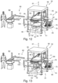
- the device also has a loading station for loading the device with film elements, the degree of automation of the device can be further increased. This allows, in particular, the number of operating personnel on the device to be reduced or used even more effectively.
- a further increase in efficiency can be achieved relatively easily by increasing the degree of automation if the device has an introduction device for introducing a carrier part to be laminated into the device, in particular into a draping space of a draping frame of the device.
- Such an insertion device can be implemented in various ways on the device, for example in the form of linear conveyors or the like.
- the insertion of the carrier part is accomplished by means of a belt conveyor or the like.
- the device has a removal device for removing a molded part or a laminated component from the device, in particular from a draping space of a draping frame or a laminating space of the device, the device can be advantageously further developed not only on the input side, but also on the output side, in that finished laminated components can also be removed from the device in an automated manner.
- Such a removal device can also be implemented in various ways on the device.
- appropriate linear conveyor systems such as belt conveyors or the like, are conceivable.
- the structural complexity of the device in this regard can be significantly reduced if the insertion device and the removal device comprise a common transfer station. This significantly reduces the number of components required for the device. This also significantly reduces the space required for setting up the device.
- a suitable transfer system can be designed as a multi-level conveyor system with different loading and unloading levels.
- a preferred design variant provides for the common transfer station to comprise a common robot device with a preferably multi-axial movable manipulator.
- a robot device can be implemented very compactly on the present device due to its compact design, flexible movement sequences, etc.
- both the insertion device and the removal device can be implemented by such a robot device, if necessary also separately from each other.
- a device for forming and/or laminating a film element with a tool which comprises an exchangeable lower tool and an exchangeable upper tool, which are exchangeable for a product change, wherein the device is characterized in that the tool comprises a draping frame equipped with a plurality of grippers, which is exchangeable for the product change together with the lower tool and/or the upper tool.
- the draping frame can be part of the tool temporarily used on the device and can therefore be used together with the lower and/or upper tool be replaced if necessary during a product change. This allows the present device to be converted to a new product much more quickly than was possible with previous solutions, in which a frame part of a comparable clamping frame is still part of the actual device.
- the carrier part to be laminated can be introduced with the carrier part holder from above into the draping space and/or the draping frame, so that, for example, the robot device described above can be used very well.
- the carrier part to be laminated can alternatively be inserted, for example, from below or from the side into the draping space and/or the draping frame.
- the device has a regulating and/or control device by means of which in particular the grippers for gripping the film element can be individually controlled.
- a tensile force measuring device for measuring the tensile forces acting between the film element and the gripper. This allows the grippers to be controlled very precisely.
- a tensile force measuring device can also be part of the control and/or regulation system.
- a device for forming and/or laminating a film element with a frame part which has a A plurality of grippers is shown, and with a forming tool or a laminating tool comprising a lower tool and an upper tool, wherein the device has tensile force measuring means by means of which tensile forces acting between the film element and the grippers can be measured and monitored.
- Such tensile force measuring devices are particularly effective in reducing the risk of critical film stretching. In particular, they allow for monitoring of unwanted tension or film stretching on a film element gripped by the grippers.
- tensile force measuring devices can be used in a variety of ways.
- tensile forces can be measured simply using strain gauges, to name just one example.
- strain gauges can be arranged, for example, on the gripper head.
- a device for forming and/or laminating a film element on a carrier part to be laminated wherein the device has a device for folding the film element laminated to the carrier part.
- a manufacturing process for a laminated component can also be further streamlined and optimized.
- the folding means of the folding device are arranged on a gripper for gripping the film element, in particular on its gripper chassis, gripper head part, and/or gripper jaw elements, and/or on a draping frame for forming and/or laminating a film element, and/or on another frame or frame part of the laminating station. This results in a wide variety of design possibilities.
- the folding means of the folding device comprise at least one folding slider element for folding the film element or the like, whereby the folding means can be provided in a structurally simple manner.
- the invention can be implemented in a very simple manner if the folding means comprise at least one folding slider element for folding the film element or the like.
- a device for laminating a film element on a carrier part with grippers for gripping the film element, with a carrier part receptacle for holding the carrier part relative to the film element and with a laminating space in which the film element is laminated onto the carrier part, wherein the device has an introduction device for introducing the carrier part receptacle and/or the carrier part into the laminating space, and wherein the introduction device has at least two degrees of freedom in space, in particular in the laminating space.
- the film element and the carrier part which have to be connected to one another, can be positioned significantly better and more differentiated relative to one another, in particular in certain areas and in particular within a laminating space or a draping space.
- the introduction device has a multi-axially movable manipulator, in particular a multi-axially movable manipulator within a laminating space or a draping space.
- manipulator describes a device by means of which a robot or robot device physically interacts with its environment and by means of which mechanical work can be performed automatically.
- a manipulator comprises a multi-jointed robot arm part, by means of which multi-axial movements in space are possible.
- the device can be constructed even more effectively if the insertion device is a discharge device for discharging the laminated component. As already described above, this makes it possible, both structurally and technically, to easily handle a carrier part to be laminated and a laminated carrier part or component.
- the device is characterized by a pressing tool with a first tool half and a second tool half, wherein the first tool half comprises the insertion device, in particular the multi-axially movable manipulator.
- the first tool half is designed as an upper tool, so that a carrier part can be introduced into a draping space or laminating space from above by means of the introduction device.
- the second tool half can accordingly be designed as a lower tool, which then comprises a mold shell part or the like.
- the device comprises a lifting device for the second tool half, by means of which the mold shell part or the like can be pressed against the carrier part receptacle of the insertion device.
- the insertion device comprises an additional support device for absorbing pressing forces.
- Such a support device can relieve the load on the manipulator in particular, so that it can be dimensioned "normally” but can still withstand high pressing forces without being damaged.
- the manipulator has an interface to a press force dissipation device, such as a hydraulic cylinder ram or the like.
- a device for forming and/or laminating a film element on a carrier part comprising grippers for gripping the film element, a carrier part receptacle for holding the carrier part relative to the film element, and a laminating chamber in which the film element is laminated onto the carrier part.
- the device has a punching device for punching the film element. Because the punching device is directly integrated into the laminating device, the finished laminated component can be freed of excess film residue directly in the laminating device, thereby significantly streamlining the manufacturing process for laminated components.
- an appropriately equipped system for producing laminated components can dispense with an additional punching station or the like.
- the term "punching device” describes any device by means of which residual film material can be separated and removed from the laminated film element. In this respect, it is irrelevant whether the film element is punched, cut, and/or torn, or the like.
- An advantageous embodiment in this regard provides for the punching device to have a segmented punching blade with a plurality of punching blade segments. Using such punching blade segments, a separation process on a film element can be carried out successively, which also advantageously reduces the punching forces acting in the laminating device. This is particularly advantageous when the laminated component is held by a manipulator, as this reduces the manipulator's workload and punching forces. This allows the manipulator to be designed with less bulk.
- the device can be constructed particularly compactly if the punching device can be arranged within the laminating space, in particular within a draping space and in particular within a draping frame.
- the device can be made even more compact if the punching device is arranged within a sealing device of a pressure difference device of the device.
- the punching device is arranged within a vacuum chamber of a pressure difference device of the device, residual film material can be removed immediately after a laminating process in the laminating device.
- the punching device is arranged opposite a carrier part holder for receiving a carrier part to be laminated, the punching device or its individual punching knife segments can be placed, for example, directly next to a mold shell part or the like.
- a device for forming and/or laminating a film element on a carrier part with grips for gripping the film element, with a carrier part receptacle for holding the carrier part relative to the film element, with a laminating space in which the film element is laminated onto the carrier part, and with a pressure difference device for generating a vacuum, wherein the pressure difference device comprises a segmented sealing device for sealing vacuum areas with a plurality of sealing slide segments.
- the segmented sealing device a vacuum space on the laminating device can be defined even more narrowly. This in turn has the positive This results in additional material savings, as a sealing device can be arranged right up to the edge-folding area of the foil element. This allows even smaller edge-folding areas or edge-folding flaps to be created on the laminated component.
- the sealing slide segments are arranged in a row, one behind the other, so that the film element can be sealed segment by segment.
- this allows a circumferential sealing device to be successively created.
- the sealing slide segments are arranged around a punching device, the device can be made even more compact.
- a segmental sealing of a vacuum chamber can be improved in particular if the sealing slide segments can be individually controlled and moved.
- a device for forming and/or laminating a film element on a carrier part comprising grippers for gripping the film element, a carrier part receptacle for holding the carrier part relative to the film element, and a laminating chamber in which the film element is laminated onto the carrier part, wherein the device has a correction device for correcting partial positional deviations of individual film element regions.
- the correction device can correct positional deviations that may have arisen after positioning, unwinding, or applying the film element relative to the carrier part. This allows laminated components to be manufactured with even greater precision and higher quality. In particular, this can significantly reduce the otherwise resulting waste of defective parts.
- Such positional deviations can occur particularly partially on the film element.
- the correction device has detection means for detecting partial positional deviations.
- detection means can be implemented very simply, for example, using optical sensors.
- the correction device can be equipped with a camera that optically records the actual position of the film element and compares it with a desired position of the film element relative to the carrier part.
- the correction device has detection means for detecting specially designed film element areas.
- Positional deviations of specially designed film element areas are extremely visually disruptive and therefore unacceptable.
- Such specially designed film element areas can be present, for example, in a blind seam, a 3D seam, two-color film materials, or the like, and are immediately visible, so that a positional deviation in this regard has often led directly to a rejected part.
- an incorrect position of a blind seam is detected by optical detection means, whereby a control unit, for example, controls and moves grippers that grip and hold the film element in such a way that the blind seam is shifted from its incorrect position into the correct position.
- a control unit controls and moves grippers that grip and hold the film element in such a way that the blind seam is shifted from its incorrect position into the correct position.
- the actual lamination process can then take place.
- a manipulator which has a carrier part holder, to which the carrier part is held, can also be manipulated by the present correction device.
- the correction device has a control unit for controlling grippers and/or the carrier part holder, so that the position of the film element relative to the carrier part can be changed at least in some areas before lamination.
- a system for producing a shaped and/or laminated component comprising an input side, an output side, at least one processing line between the input side and the output side, and a device for shaping and/or laminating a film element, the system comprising a device according to one of the features described here.
- laminated components in particular can be manufactured more effectively and cost-effectively.
- the present object is achieved in particular by a system for producing a shaped and/or laminated component with at least one processing line and with a device for shaping and/or laminating a film element, wherein the system has a feeding and/or inserting device for feeding and/or inserting a film element to grippers or into grippers of a draping frame of the device, and/or an insertion device for introducing a carrier part to be laminated to a lower tool of the device, and/or a removal and/or provision device for removing or providing a shaped part or a laminated component from the device.
- a system can also ensure very compact production, in particular of laminated components.
- a supply device is designed to transfer a laminated component to a subsequent processing station of the system, in which the laminated component can then be further processed.
- the system can advantageously be used to produce almost any shaped and/or laminated components, such as automotive components, in particular instrument panels, interior door panels or the like.
- the system can be constructed particularly simply if the insertion device and removal and/or provision device comprise a common robot device with a preferably multi-axial movable manipulator.
- a removal device can simultaneously embody an insertion device for carrier parts and a provision device for laminated components, particularly if the removal device is configured to grip and hold a carrier part on the designated B-side of the laminated component.
- An advantageous embodiment provides for the system to have a loading station for loading the device with film elements, wherein the loading station is located inline in the processing line upstream of the device.
- a loading station can further increase the level of automation of the system, allowing, in particular, laminated components to be manufactured more efficiently.
- a further advantageous embodiment provides for the system to have an adhesive application station for applying adhesive to the film element, with the adhesive application station being located inline upstream of the device in the processing line. This allows the production of laminated components, in particular, to be further compressed in terms of space and time.
- the adhesive application station is installed inline in the processing line downstream of a loading station and/or upstream of a feeding and/or insertion device of the device, it is possible to first place the film elements in an orderly manner on the processing line of the system in order to then precisely coat the film elements with adhesive using the adhesive application station. This can reduce the residence time of film elements prepared with adhesive before they are further processed in the draping frame of the device.
- the processing of the film element can be further streamlined if the system has a heating unit for heating the film element, wherein in particular the heating unit is integrated in a feeding and/or inserting device for feeding and/or inserting a film element to grippers or into grippers of a draping frame of the device.
- the system comprises a discharge station for discharging a molded part or a laminated component, wherein the discharge station is arranged inline downstream of the processing line of a trimming station and/or a punching and/or folding station, whereby the finished components can be automatically removed from the upstream processing stations.
- a system for producing a shaped and/or laminated component comprising an input side, an output side, at least one processing line between the input side and the output side, and a device for shaping and/or laminating a film element, the device comprising a device for folding the film element laminated to the carrier part.
- the device combines a laminating and folding function, a separate folding station with a folding device can be omitted, which means that the system can be built more compactly.
- a method for forming and/or laminating a film element in which the film element is inserted into open grippers and subsequently gripped by the grippers, and in which the film element is further brought into operative contact with a formed part or with a carrier part to be laminated, wherein the film element is at least partially unwound and/or applied by means of grippers only to the contour of the formed part or the carrier part.
- the film element can be brought into active contact or initial contact with the molded part or carrier part almost or preferably entirely without tensile forces or stresses.
- a tensile force-free, stress-free, or stretch-free unwinding or attachment of the film element to the carrier part can be controlled in particular as a function of path parameters, force parameters, speed parameters, and/or temperature parameters.
- the film element is brought into operative contact with the mold and/or carrier part by means of a gripper, avoiding any stretching or drawing of the film element,
- the film element can then be at least partially unwound, in particular by means of a draping frame, more precisely by means of a gripper, without critical tensile forces on the surface of the carrier part to be laminated, in particular before the film element is laminated onto the carrier part with the aid of a differential pressure.
- a particularly advantageous method variant provides for the film element to be applied to the molded part or carrier part at least partially without stretching and/or at least with reduced stretching, with a partial film stretch of less than 10%, preferably less than 5%, particularly before the film element is laminated to the carrier part using differential pressure. This allows critical film stretching to be avoided, particularly before the film element is finally laminated to the carrier part.
- the film element is at least partially applied to the molded part or the carrier part with a partial film stretch of less than 5%, a particularly high optical quality can be achieved if this is required for particularly high-quality products.
- the film element can be processed particularly gently on the corresponding device and, in addition, a desired appearance can be maintained on the film element.
- grippers and in particular gripper jaw elements thereof are moved on and/or in a draping space, in particular of a draping frame, with up to seven degrees of freedom or more in order to unwind and/or form the film element at least partially on the contour of the molded part or the carrier part.
- the film element can be handled particularly gently when it is inserted into the draping space or, in particular, into the draping frame if the film element is inserted into the open grippers without tension.
- the film element can be transferred to the grippers and inserted in a reliable manner if the grippers are moved into an insertion position before the film element is inserted, in which the film element is placed on a lower gripper jaw element of the respective gripper.
- the grippers are closed sequentially after the film element has been inserted, the risk of unwanted distortions or tensions on the film element can be reduced.
- a method for forming and/or laminating a film element in which the film element is gripped by grippers in order to bring it into operative contact with a molded part or a carrier part to be laminated, wherein tensile forces acting between the film element and the grippers are measured and monitored by means of tensile force measuring means when the film element is brought into operative contact with the part to be laminated.
- the risk of critical film stretching can be reduced cumulatively or alternatively, particularly effectively.
- the control of undesired tensions or film stretching on a part gripped by the grippers is essential. Foil element is possible. This is particularly advantageous for a three-dimensional carrier part.
- a particularly advantageous method variant provides for the tensile forces acting between the film element and the grippers to be measured and monitored using tensile force measuring devices when the film element is at least partially unwound and/or applied to the contour of the molded part or the carrier part using the gripper. This is also particularly advantageous for a three-dimensional carrier part. This enables particularly good preparation, especially for a subsequent lamination process, even before the film element is laminated to the carrier part, for example, using a vacuum.
- the grippers can be addressed depending on the determined tensile forces and by the control and/or regulation device described above.
- a method for forming and/or laminating a film element in which the film element is gripped by grippers in order to bring it into operative contact with a molded part or a carrier part to be laminated, wherein the film element gripped by the grippers is heated before and/or during the molding of the film element gripped by the grippers onto the molded part or the carrier part to be laminated.
- the foil element and especially the adhesive applied to it, can be optimally prepared for subsequent lamination.
- the foil element can be relieved of tension within the draping space or frame.
- suitable heating devices of a heating unit are positioned above and/or below the grippers arranged within a draping or laminating space.
- a suitable method variant provides that a heating device is temporarily arranged above the grippers and/or a heating device is temporarily arranged below the grippers in order to heat the film element gripped by the grippers.
- such a heating device can also be moved from outside into a draping room or laminating room, in particular into a draping frame, when the film element has already been gripped by the grippers.
- a method for forming and/or laminating a film element in which the film element is gripped by grippers in order to bring it into operative contact with a molded part or a carrier part to be laminated, wherein the method is characterized in that the film element is fed to the grippers by means of a feeding and/or inserting movement and the film element is heated during the feeding and/or inserting movement.
- a particular advantage here is that the feeding and/or insertion section does not have to be equipped with heating devices over its entire length.
- At least one heating device is moved transversely to a feed direction of a lower tool and/or an upper tool, in particular, is introduced into a draping space defined by a draping frame. This makes it possible to heat the film element almost continuously during or after loading into the feed and/or insertion section and, if necessary, into a draping space or laminating space or into the draping frame.
- the present methods can be further optimized if a film element and/or a heating unit are moved relative to grippers and/or a draping frame while a film element is being formed into a molded part or laminated onto a carrier part.
- a new film element can already be heated while, for example, another film element is already being laminated onto a carrier part.
- the film element is pre-tensioned by means of the grippers only during and/or after heating, at least partially without stretching and/or at least with reduced stretching, with a partial film stretch of less than 10%, preferably less than 5%, lower tensile forces need to be absorbed by the film material in order to be pre-stretched.
- the process can be carried out more efficiently in terms of energy if heating elements of a heating device are switched on depending on the size of the foil element.
- the method can be carried out in a more customer-specific manner if the film element is formed or laminated onto the molded part or the carrier part by means of a first feed movement, in particular a vertical lifting movement, of a lower tool and/or a feed movement, in particular a vertical lowering movement, of an upper tool.
- a first feed movement in particular a vertical lifting movement, of a lower tool and/or a feed movement, in particular a vertical lowering movement, of an upper tool.
- the carrier part can advantageously be brought closer to the film element by means of an upper tool, in particular with a multi-axial movement.
- grippers are actively driven in the feed direction of the lower tool and/or against the feed direction of the lower tool and/or transversely to the feed direction when a lower tool is fed to the film element gripped by the grippers, film stretching can be avoided particularly effectively, especially if the grippers are moved depending on measured tensile forces.
- a further increase in efficiency can be achieved if, after being laminated to the carrier part, the film element is optionally folded at least partially around an edge of the carrier part using a gripper. This allows the film element to be folded within the draping frame.
- this allows the folding to take place at a time when the film element and/or the adhesive still contains more heat energy than at a later time.
- the film element is at least partially folded around the carrier part within the draping frame.
- the laminated carrier part can be further processed as quickly as possible if the formed film element or the carrier part laminated with the film element is made available for further processing by means of a removal device on at least one downstream processing device after being released by the grippers.
- Such a processing machine can be, for example, a folding device, a punching device, or the like. This allows the laminated carrier part to be further processed as quickly as possible.
- a method for converting a device for forming and/or laminating a film element in which method a tool of the device is exchanged for converting the device to a different product, wherein the upper tool train and/or the lower tool of the tool are exchanged, and in which method in addition to the upper and/or lower tool a draping frame including gripper for gripping the film element is also exchanged.
- the draping frame can be part of the tool temporarily installed on the fixture and can therefore be replaced together with the lower and/or upper tool if necessary during a product change. This allows the fixture to be converted to a new product much more quickly than with previous solutions, where a frame part of a comparable clamping frame is still part of the fixture itself.
- a method for forming and/or laminating a film element on a carrier part in which the film element and the carrier part are positioned relative to one another for forming and/or laminating, wherein the carrier part is moved multiaxially in space, in particular in a draping space and/or a laminating space, for positioning relative to the film element.
- the film element and the carrier part which have to be connected to each other, can be positioned significantly better and more differentiated relative to each other, in particular before lamination, in particular in certain areas and in particular within a lamination space or a draping space.
- the carrier part is brought closer to the film element in a multi-axial manner in space, in particular in a draping space and/or a laminating space, for positioning relative to the film element.
- a further improvement in the handling of the film element and the carrier part relative to each other can be achieved if the film element is gripped by grippers for positioning relative to the carrier part, whereby grippers are moved multiaxially in space, in particular relative to the carrier part.
- the carrier part can be moved multiaxially in space in different ways, for example by means of a tool table that can be moved translationally along two axes and on which the carrier part holder is clamped.
- the carrier part holder and thus also the carrier part can be moved particularly flexibly in space and thus positioned relative to the film element if the carrier part is held by means of a multi-axially movable manipulator and moved relative to the film element.
- a carrier part holder of a device for laminating a film element onto a carrier part is moved multiaxially in space, in particular in a draping space and/or a laminating space.
- the object of the invention is also achieved according to a fourth aspect by a method for forming and/or laminating a film element, in which the film element is gripped by grippers in order to bring it into operative contact with a molded part or a carrier part to be laminated, characterized in that the film element gripped by the grippers is heated before and/or during the molding of the film element gripped by the grippers onto the molded part or the carrier part to be laminated, wherein the film element is at least partially folded around an edge of the carrier part by means of grippers after being laminated onto the carrier part.
- a method for producing a laminated component from a film element and a carrier part in which the film element is laminated onto the carrier part on a laminating device, and in which the laminated component is subsequently removed from the laminating device and made available for further processing, wherein the carrier part or the laminated component is held on its B-side by means of a removal device for removal from the laminating device.
- the carrier part or the laminated component is held exclusively on its B-side, the risk of damage to the A-side is significantly reduced and can ideally be completely eliminated.
- a laminated component has an A-side (good side) and a B-side (bad side).
- the B-side can be the back of the laminated component or the carrier part, which is no longer visible when the laminated component is installed and is therefore not fully laminated.
- the A-side on the other hand, can define the visible area in the installed state of the laminated component.
- a preferred method variant provides that the carrier part or the laminated component is removed from the laminating device by means of the removal device held at its B-side and is transferred to a subsequent processing station while being held continuously at its B-side, whereby the A-side can be better protected.
- a preferred method variant advantageously provides that the carrier part or the laminated component held on its B-side is continuously held by the removal device during removal from the laminating station, during transfer from the laminating device to a downstream processing station, in particular to a downstream folding device, and/or during insertion into a processing position at the downstream processing station, in particular into a folding processing position at the downstream folding device.
- the handling process of the carrier part up to the laminated component can be further simplified considerably if the carrier part is gripped and held continuously only once by the removal device, namely on its B-side, from its picking up from a provision position, in particular from a carrier part magazine, into a draping position and a laminating position of the laminating device as well as into a processing position of a downstream processing station.
- the removal device is also the insertion device, with these two devices constituting a common transfer device or transfer station, as already described above.
- This transfer station advantageously comprises a robot device with a multi-axially movable manipulator.
- both critical film material stretching can be prevented and film consumption can be significantly reduced.
- the possibility of using high-precision foil element cutting means that a previously unattainable level of automation can be achieved in devices for forming and/or laminating a foil element and systems for producing a formed and/or laminated component.
- film material consumption can be significantly further reduced if the film element is partially stretched more in designated areas of a laminated component that will not be visible later than in designated visible areas of the laminated component.
- the present invention is applicable to almost all common laminating processes, such as press laminating, vacuum laminating, in-mould graining (IMG) processes or the like.
- the film element after being unwound from the carrier part or placed on the carrier part, is formed onto the molded part or the carrier part to be laminated by applying a differential pressure.
- differential pressure in the meaning of the invention describes a wide variety of pressure loadings of the components involved, in particular of the film element, for example by means of a negative pressure or vacuum, whereby the film element can be brought into active contact with the carrier part in a forming manner, either exclusively or in a supporting manner.
- a corresponding pressure application can also be carried out by pressing devices or the like.
- the invention disclosed here includes not only vacuum lamination, but also press lamination or the like.
- the present device can have a vacuum device with a vacuum tool and/or a pressing device with a pressing tool as a differential pressure generating device.
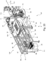
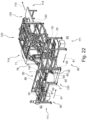
- a draping frame 1 of the invention is shown as an example, which carries a plurality of motor-driven grippers 2.
- the draping frame 1 has a frame part 3 which is surrounded by a housing 8 at least on its four side wall areas 4, 5, 6 and 7.
- the draping frame 1 is at least partially open on the underside 9 and on the top side 10.
- the housing 8 of the draping frame 1 is open above and below a centrally arranged draping space 15 of the draping frame 1, with regard to the illustration according to the Figure 1 the upper side of the housing is dismantled to provide a view of the frame part 3 and the grippers 2 movably mounted on it.
- the frame part 3 of the draping frame 1 is characterized by several longitudinal cross members 16 (numbered here only as an example) and transverse cross members 17 (numbered only as an example), on which the grippers 2 are held within the draping frame 1.
- the individual grippers 2 are each mounted on the draping frame 1 or in the draping space 15 in such a way that the grippers 2 have a total of at least seven degrees of freedom, whereby a film element 20 (see example Figure 3 ) can be grasped in an extremely differentiated manner and can be draped and guided within the draping space 15.
- the draping space 15 is heated by heating devices that can be moved into it (not shown here, see for example from Figure 10 ) can be heated from both the bottom 9 and the top 10.
- Such a heating device can basically be introduced into the draping frame 1 or its draping space 15 from any side area 4, 5, 6 or 7, but the front side area 6 or the rear side area 7 are preferred for this purpose.
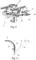
- a gripper 2 of the draping frame 1 is shown as an example, wherein the gripper 2 has a gripper chassis 22, on the front side 23 of which a gripper head part 24 is arranged, on which the actual gripper jaw elements 25 and 26 of the gripper 2 are mounted.
- the gripper head part 25 has at least a further degree of freedom, so that in particular the gripper jaw elements 26 and 27 in the draping space 15 have at least 7 degrees of freedom.
- the gripper head part 25 of the gripper 2 is three-dimensionally adjustable relative to the gripper chassis 22 of the gripper 2, wherein the degrees of freedom achieved at the gripper head part 25 are different from the degrees of freedom of the gripper chassis.
- a further special feature of the gripper 2 is that the gripper 2 has temperature-controlled gripper jaw elements 26 and 27, so that these gripper jaw elements 26 and 27 can adapt to special conditions or requirements in terms of temperature with regard to a film element 20 to be gripped by means of activatable temperature control means 28.
- a cooled gripper jaw element 26 or 27 is particularly advantageous when the film element 20 is to be laminated onto a carrier part 30 (see for example Figure 3 ) is provided with adhesive, since the cooled gripper jaw element 26 or 27 can form a less intensive bond with the adhesive, whereby the cooled gripper jaw element 26 or 27 is significantly less contaminated by the adhesive.
- the lower gripper jaw element 26 can be tempered in the sense of cooling, since only this side of the film element 20 which is covered with adhesive comes into operative contact when this film element 20 is inserted into the gripper 2.
- the gripper 2 is equipped with tensile force measuring devices 29, which are arranged on the gripper head part 25. Using the tensile force measuring devices 29, tensile forces acting between the film part 20 and the gripper 2 can be detected and measured. Depending on the determined tensile forces, the gripper 2 can then be moved within the draping space 15 and relative to the film element 20 in order to avoid critical film stretching in accordance with the invention.
- the film element 20 is even unwound completely free of tensile forces onto the contour 31 of the carrier part 30, so that, on the one hand, the film element 20 can be laminated in a particularly gentle manner to the material and surface.
- the film element 20 can be applied to the carrier part 30 to be laminated by the grippers 2 with their seven degrees of freedom with virtually no stretching or at least with reduced stretching.
- the gripper head part 25 of the gripper and in particular also the gripper jaw elements 26 and 27 pass through an approach curve 32 in order to unwind the film element 20 in the simplest case by a movement of the gripper 2 in the Z and Y directions onto the carrier part in the sense of the invention without any tensile forces.
- the film element 20 can be brought into operative contact with the carrier part 25 to be laminated at least by means of some of the grippers 2, avoiding any stretching or drawing of the film element 20, so that the film element 20 can stretch only very slightly, if at all, at least when being attached to the carrier part 30 to be laminated with the grippers 2, so that even after the film element 20 has been laminated onto the carrier part 30, there is hardly any distortion on the visible surface thereof.
- a first embodiment of an advantageous device 50 for forming and/or laminating a film element 20 onto a carrier part 30 is shown by way of example in accordance with the illustrations according to the Figures 10 to 19 shown and explained here, using the individual Figures 10 to 19 different process steps on the device 50 are shown as examples.
- the basic concept of the device 50 is also relevant for the other embodiments. Therefore, the device 50 will also be described by way of example for the other embodiments to avoid repetition.
- the device 50 is primarily characterized by a frame part 3 of a laminating tool 51, which in this embodiment comprises a draping frame 1 with a plurality of motor-driven grippers 2.
- the device 50 is further characterized by further components of the laminating tool 51, which essentially comprises a lower tool 52 and an upper tool 53 (see in particular also from Figure 15 ) include.
- the draping frame 1 and thus also the grippers 2 are mounted in a frame 56 of the device 50 in a height-adjustable manner by means of a displacement mechanism 55, so that the entire draping frame 1 is mounted on the frame 56 in a height-adjustable manner along a vertical displacement axis 57 of the device 50.
- the lower tool 52 is placed below the draping frame 1 on a base part 58 of the frame 56, wherein the lower tool 52 comprises one or more mold shell parts 59, which in turn are arranged on a base 60 of the base part 58.
- the upper tool 53 comprises a carrier part holder 63, by means of which one or more carrier parts 30 to be laminated can be introduced automatically, in particular into the draping frame 1 of the device 50.
- a corresponding insertion device 65 is provided on the device 50, which in this embodiment comprises a robot device 70 with a multi-axial movable manipulator 71.
- this robot device 70 with its multi-axial movable manipulator 71 serves not only to introduce the carrier part 30 to be laminated into the device 50, in particular into the draping space 15 of the draping frame 1, but also also the removal of the finished laminated component 37, 38 or 39 (cf. Figures 4 to 9), so that the robot device 70 also represents a removal device 75 on the device 50.
- the device 50 also has a feeding and/or insertion device 80, by means of which one or more film elements 20 can be guided into the draping frame 1, in such a way that the film element 20 can be immediately inserted into the opened grippers 2, in particular onto the lower gripper jaw elements 26 of the opened grippers 2.
- the feeding and/or inserting device 80 has a feeding and/or inserting section 81, along which the respective film element 20 can be conveyed from a feeding position 82 into the draping space 15.
- the feed and/or insertion section 80 or its feed and/or insertion section 81 runs transversely to the vertical displacement axis 57 of the device 50.
- the draping frame 1 is arranged to be displaceable transversely to this feed and/or insertion section 81 by means of the displacement mechanism 55.
- the feeding and/or inserting device 80 is characterized in particular by at least one movable heating unit 85 for heating the respective film element 20 outside the draping space 15 of the draping frame 1, which has two heating devices 86 and 87.
- the heating unit 85 is integrated into the feeding and/or inserting device 80 in such a way that the heating unit 85 can be moved continuously, for example, together with the respective film element 20, which is moved along the feeding and/or inserting path 81 in the direction of the draping space 15 of the draping frame 1.
- the upper heating device 86 and the lower heating device 87 of the heating unit 85 are moved together with the film element 20 along the feed and/or insertion path 81, so that the respective film element 20 can be continuously heated both from above and from below.
- the lower heating device 87 is designed such that the respective film element 20 can be transported by means of this lower heating device 87 from the loading position 82 to the draping frame 1 of the device 50.
- a film element 20 is already placed on the lower heating device 87 and is on its way from the loading position 82 to the draping frame 1 with the help of the movable heating unit 85.
- the film element 20 is now heated on both sides by means of the upper heating device 86 and the lower heating device 87, it is simultaneously transported along the feed and/or insertion path 81 with the heating devices 86 and 87.
- the draping frame 1 is located in a feed position 89, in which the film element 20 transported by means of the feed and/or insertion device 80 can be transported into the draping space 15.
- the robot device 70 is still in a starting position 90, in which at least one carrier part 30 to be laminated is received in the carrier part holder 63, specifically from a carrier part magazine 100.
- the heating unit 85 with the film element 20 is shortly before being fed or inserted into the draping frame 1.
- the heating unit 85 together with the foil element 20 heated thereby is completely retracted into the device 50.
- the lower heating device 87 moves upwards towards the draping frame 1, so that in this insertion position 103 the heated film element 20 can be transferred to the grippers 2 of the draping frame 1 or inserted into these grippers 2.
- the heating unit 85 With its heating devices 86 and 87 moves back to the loading position 82 in order to receive one or more new film elements 20 there.
- the robot device 70 After the successful lamination of the carrier part 30 with the film element 20, the robot device 70 removes the finished laminated component 37, 38 or 39 from the draping frame 1 and places it in a preferably cooled trimming station 104 (only shown as an example in Figure 18 indicated), whereby the robot device 70 is in a provision position 105 in which it provides the finished laminated component 37, 38 or 39 for further processing or the like on the device 50.
- the manipulator 71 of the robot device 70 moves the carrier part holder 63 back to the carrier part magazine 102 in order to pick up the carrier part 30 to be laminated again.
- a new film element 20 is transported along the feed and/or insertion path 81 in the direction of the draping frame 1 by means of the feed and/or insertion device 80, which is simultaneously heated on both sides by means of the heating unit 85.
- a first system embodiment is shown with a first system 107 for producing a shaped and/or laminated component 37, 38 or 39, wherein the first system 107 has an alternative, second device 108 integrated for shaping and/or laminating a film element 20. More precisely, the second device 108 is integrated into the processing line 110 of the first system 107, wherein the second device 108 is followed inline by a punching and folding station 114 (not shown).
- the processing line 110 runs from an input side 111 of the first system 107 to an output side 112 of the first system 107.
- the second device 108 has essentially the same structure as the previously described device 50 from the Figures 10 to 19 , and the device 108 accordingly comprises the draping frame 1 with the motor-driven grippers 2 movably arranged thereon for gripping the film element 20, the feeding and/or inserting device 80 and the removal device 85 with the robot device 70 as well as the carrier part magazine 100.
- the device 108 comprises two heating units 85 on its feeding and/or insertion device 80, whereby the cycle times on the alternative device 108 or on the system 107 can be advantageously reduced.
- the cycle times can be less than 40 seconds.
- the film elements 20 are alternately inserted from the respective heating unit 85 into the draping frame 1.
- the respective finished laminated component 37, 38 or 39 (cf. Figures 4 to 9 ) is transferred by the robot device 70 to the inline punching and folding station 114 and stored there for further processing.
- the alternative device 108 otherwise has the same structure as the one shown in the Figures 10 to 19 described device 50, so that for a more detailed structure and operation of the alternative device 108, reference is made to the description of the device 50.
- a second system 116 for producing a molded part or laminated component 37, 38 or 39 with a processing line 110 is shown.
- a third device 117 for forming and/or laminating a film element 20 and a punching and folding station 114 connected downstream of this device 117 are arranged, at which there is additionally a discharge station 119 for discharging the finished laminated components 37, 38 and 39 (cf. Figures 4 to 9 ) with a discharge table 120.
- a discharge station 119 for discharging the finished laminated components 37, 38 and 39 (cf. Figures 4 to 9 ) with a discharge table 120.
- the third device 117 also has essentially the same structure as the previously described device 50 from the Figures 10 to 19 , and the third device 107 accordingly comprises the draping frame 1 with the motor-driven grippers 2 movably arranged thereon for gripping the film element 20, the feeding and/or inserting device 80 and the removal device 85 with the robot device 70 as well as the carrier part magazine 100.
- a third system design example shows the Figure 22 , in which a third system 123 has in its processing line 110 two feeding and/or insertion devices 80 of a fourth device 124 for forming and/or laminating the film element 20.
- the fourth device 124 accordingly also has two heating units 85, so that here too an advantageous reduction in cycle time can be achieved.
- This fourth device 124 has essentially the same structure as the previously described device 50 from the Figures 10 to 19 .
- the fourth device 124 thus comprises the draping frame 1 with the motor-driven grippers 2 movably arranged thereon for gripping the film element 20, the feeding and/or insertion device 80 in duplicate, the removal device 85 with the robot device 70, and the carrier part magazine 100.
- the fourth device 124 is then followed inline by the punching and folding station 114 and the discharge station 119 for discharging the finished laminated components 37, 38 and 39 (cf. Figures 4 to 9 ).
- FIG. 23 is a fourth embodiment of a system with regard to a double system 126 for producing a molded part or a laminated component with two processing lines 110, wherein all machines are present twice on the double system 126.
- the double system 126 has two fifth devices 127, each fifth device 127 having the draping frame 1 with the motor-driven grippers 2 movably arranged thereon for gripping the film element 20, the feeding and/or inserting device 80 and the removal device 85 with the robot device 70 as well as the carrier part magazine 100.
- two punching and folding stations 114 and two discharge stations 119 are connected downstream of the fifth devices 127 inline of the processing lines 110, whereby the output rate can be doubled in the double system 126.
- This further double system 130 also has two processing lines 110, but compared to the first double system 126 from the Figure 23 on the input side 111 of the further double system 130 there is also an adhesive application station 131.
- this adhesive application station 131 includes two adhesive application lines 132, whereby these two adhesive application lines 132 are served by a common adhesive application device 133.
- the adhesive application device 133 is equipped with an adhesive application robot 134 with a corresponding application manipulator 135.
- the adhesive application device 133 with its adhesive application robot 134 is arranged between the two adhesive application lines 132 of the adhesive application station 131, so that both adhesive application lines 132 can be easily reached and operated by the adhesive application manipulator 135.
- sixth devices 136 Downstream of the adhesive application station 131, according to the dual processing lines 110, there are also two sixth devices 136 for forming and/or laminating a film element 20.
- the respective sixth device 136 again comprises the feeding and/or insertion device 80 for feeding and/or inserting the film element 20 into the draping frame 1, with the carrier part magazine 100 being laterally assigned to each sixth device 136.
- the sixth devices 136 each also comprise the removal device 75 in the form of the robot device 70.
- the respective sixth device 136 is again followed by the punching and folding station 114.
- the discharge station 119 is again located on each processing line.
- a fully automated system 140 for producing a molded part or a laminated component 37, 38 or 39 with a processing line 110 and a seventh device 141 for forming and/or laminating a molded element 20 is shown.
- This seventh device 141 again has essentially the same structure as the previously described device 50 from the Figures 10 to 19 .
- the seventh device 141 accordingly comprises the draping frame 1 with the motor-driven grippers 2 movably arranged thereon for gripping the film element 20, the feeding and/or inserting device 80 and the removal device 85 with the robot device 70 as well as the carrier part magazine 100.
- the fully automated system 140 additionally has a feeding station 142 on its input side 111 for feeding the seventh device 141 for forming and/or laminating the shaped element 20.
- the feeding station 141 has a gripping device 143 for picking up film elements 20 and depositing these film elements 20 on the feed and/or insertion line 81.
- film elements 20 can be transferred to the feeding and/or insertion section 81 of the feeding and/or insertion device 80 of the seventh device 141 largely without operating personnel.
- such a loading station 141 can also be installed upstream of all the devices 50, 108, 117, 124, 127 and 136 described above, as well as the corresponding systems 111, 116, 123, 126 and 130, in order to save operating personnel there as well.
- this feeding station 142 is shown as an example only with regard to the fully automated system 140.
- a prefabricated foil element 20, as can be used in the present invention is shown schematically, while according to the Figure 28 an optimized pattern 150 with a multitude of designated foil elements 20 is shown.
- These designated film elements 20 can be placed particularly close to one another and thus with very little residual film grid material 151 in between on the optimized cutting pattern 150, since the film elements 20 cut out therefrom can only be reliably gripped by the grippers 2 according to the invention or the draping frame 1 according to the invention.
- the laminating device is shown with a plurality of folding means 160 or folding sliders, wherein the folding means 160 are provided in a draping space 15 of the device 1.
- the folding means 160 are attached to the draping frame 1 next to the grippers 2.
- the folding means 160 are arranged on the grippers 2.
- the folding means 160 are arranged on a frame (not separately numbered here) of the laminating device.
- the folding means 160 are located on the frame part 3 of the laminating device,
- the gripper 170 has a gripper chassis 171, on the front side 172 or end face 173 of which a gripper head part 174 is arranged, on which the actual gripper jaw elements 175 and 176 of the gripper 170 are mounted, wherein in the top view only the upper gripper jaw element 176 can be seen.
- the gripper 170 faces a draping space 15 with its gripper head part 174.
- the degree of freedom 177 results from the rotational axis 180 of the rotary drive 181, wherein the rotary drive 181 has a worm gear 182.
- the gripper jaw elements 175 and 176 on the gripper head part 174 can be rotated motor-driven and automatically about the rotational axis 180 relative to the gripper chassis 171.
- the rotational axis 180 is perpendicular to the end face 173, so that this is a horizontal axis (not numbered again).
- the further degree of freedom 178 results around the vertical axis 185, around which the gripper jaw elements 175 and 176 can be pivoted manually.
- the device 190 has a draping space 15 or laminating space 15 in which a lower tool 52 is arranged.
- the lower tool 52 can have a mold shell part 59 (not shown).
- the further device 190 or its lower tool 52 has both punching knife segments 191 (numbered here only as an example) of a punching device 192 and sealing slide segments 194 of a sealing device 195 of a pressure difference device not shown further.
Landscapes
- Engineering & Computer Science (AREA)
- Mechanical Engineering (AREA)
- Manufacturing & Machinery (AREA)
- Laminated Bodies (AREA)
- Lining Or Joining Of Plastics Or The Like (AREA)
- Coating Apparatus (AREA)
Claims (10)
- Pince (2 ; 170) pour un dispositif (50 ; 108 ; 117 ; 124 ; 127 ; 136 ; 141 ; 190) de formage et/ou d'application avec laminage d'un élément en feuille (20), en particulier pour un cadre de drapage (1), ayant au moins deux éléments (26, 27 ; 175, 176) formant mâchoires de pince opposés et mobiles l'un par rapport à l'autre pour saisir l'élément en feuille (20), la pince (2 ; 170) présentant des moyens de pliage (160) pour plier un bord de feuille autour d'un bord d'une pièce de support (30) recouverte par l'élément en feuille (20).
- Pince (2 ; 170) selon la revendication 1, caractérisée en ce que les moyens de pliage (160) sont agencés sur lesdits au moins deux éléments (26, 27 ; 175, 176) formant mâchoires de pince opposés et mobiles l'un par rapport à l'autre.
- Pince (2 ; 170) selon la revendication 1 ou la revendication 2, caractérisée en ce que les moyens de pliage (160) sont agencés sur un châssis de pince (22 ; 171) et/ou sur une partie de tête (25 ; 174) de pince.
- Cadre de drapage (1) pour former et/ou appliquer avec laminage un élément en feuille (20), comprenant un espace de drapage (15) et une pluralité de pinces (2 ; 170) entraînées par moteur pour saisir l'élément en feuille (20), le cadre de drapage (1) présentant des moyens de pliage (160) pour plier un bord de feuille autour d'un bord d'une pièce de support (30) recouverte par l'élément en feuille (20).
- Cadre de drapage (1) selon la revendication 4, caractérisé en ce que les moyens de pliage (160) sont prévus sur au moins une des pinces (2 ; 170), sur un châssis (22 ; 171) de pince de ladite au moins une pince (2 ; 170) et/ou sur une partie de tête (25 ; 174) de pince de ladite au moins une pince (2 ; 170) et/ou sur au moins un élément (26, 27 ; 175, 176) formant mâchoire de pince de ladite au moins une pince (2 ; 170).
- Cadre de drapage (1) selon la revendication 4 ou la revendication 5, caractérisé en ce que les moyens de pliage (160) sont agencés sur le cadre de drapage (1) ou sur une partie de cadre (3) de celui-ci.
- Cadre de drapage (1) selon l'une des revendications 4 à 6, caractérisé en ce que les moyens de pliage (160) comprennent au moins un élément coulissant de pliage pour plier l'élément en feuille (20), ou similaire.
- Dispositif (50 ; 108 ; 117 ; 124 ; 127 ; 136 ; 141 ; 190) pour former et/ou appliquer avec laminage un élément en feuille (20) comprenant une pluralité de pinces (2 ; 170) et comprenant un outil de formage ou un outil de laminage (51), l'outil de formage ou l'outil de laminage (51) comprenant un outil inférieur (52) et un outil supérieur (53), le dispositif (50 ; 108 ; 117 ; 124 ; 127 ; 136 ; 141 ; 190) comprenant une pince selon l'une des revendications 1 à 3, le dispositif (50 ; 108 ; 117 ; 124 ; 127 ; 136 ; 141 ; 190) présentant une unité de chauffage (85) pour chauffer l'élément en feuille (20), qui est apte à être agencée au moins partiellement temporairement à l'intérieur d'un espace de drapage (15), en particulier du cadre de drapage (1) du dispositif (50 ; 108 ; 117 ; 124 ; 127 ; 136 ; 141 ; 190).
- Dispositif (50 ; 108 ; 117 ; 124 ; 127 ; 136 ; 141 ; 190) pour former et/ou appliquer avec laminage un élément en feuille (20) comprenant une pluralité de pinces (2 ; 170) et comprenant un outil de formage ou un outil de laminage (51), l'outil de formage ou l'outil de laminage (51) comprenant un outil inférieur (52) et un outil supérieur (53), le dispositif (50 ; 108 ; 117 ; 124 ; 127 ; 136 ; 141 ; 190) comprenant un cadre de drapage selon l'une des revendications 4 à 7, le dispositif (50 ; 108 ; 117 ; 124 ; 127 ; 136 ; 141 ; 190) présentant une unité de chauffage (85) pour chauffer l'élément en feuille (20), qui est apte à être agencée au moins partiellement temporairement à l'intérieur d'un espace de drapage (15), en particulier du cadre de drapage (1) du dispositif (50 ; 108 ; 117 ; 124 ; 127 ; 136 ; 141 ; 190).
- Procédé de formage et/ou d'application avec laminage d'un élément en feuille (20), dans lequel l'élément en feuille (20) est saisi par des pinces (2 ; 170) afin d'être mis en contact actif avec une pièce moulée ou une pièce de support (30) à recouvrir, caractérisé en ce que l'élément en feuille (20) saisi par les pinces (2 ; 170) est chauffé avant et/ou pendant le formage de l'élément en feuille (20) saisi par les pinces (2 ; 170) sur la pièce moulée ou la pièce de support (30) à recouvrir, l'élément en feuille (20) étant plié au moins partiellement autour d'un bord de la pièce de support (30) après avoir été laminé sur la pièce de support (30) au moyen de pinces (2 ; 170).
Applications Claiming Priority (5)
| Application Number | Priority Date | Filing Date | Title |
|---|---|---|---|
| DE102018007401 | 2018-09-19 | ||
| DE102018128459 | 2018-11-13 | ||
| DE102019000300.4A DE102019000300A1 (de) | 2018-09-19 | 2019-01-18 | Greifer für eine vorrichtung zum formen und/oder kaschieren eines folienelements, drapierrahmen, vorrichtung zum formen und/oder kaschieren eines folienelements, anlage zum fertigen eines formteils oder eines kaschierten bauteils, verfahren zum formen oder kaschieren eines folienelements sowie verfahren zum fertigen eines kaschierten bauteils |
| PCT/DE2019/100798 WO2020057692A1 (fr) | 2018-09-19 | 2019-09-09 | Organe de préhension pour un cadre de parement et pour un dispositif, cadre de parement, dispositif et procédé pour façonner et/ou laminer un élément en film, installation pour fabriquer une pièce préformée ou un composant laminé, procédé de transformation d'un tel dispositif, procédé de fabrication d'un composant laminé |
| EP19787147.8A EP3853002A1 (fr) | 2018-09-19 | 2019-09-09 | Organe de préhension pour un cadre de parement et pour un dispositif, cadre de parement, dispositif et procédé pour façonner et/ou laminer un élément en film, installation pour fabriquer une pièce préformée ou un composant laminé, procédé de transformation d'un tel dispositif, procédé de fabrication d'un composant laminé |
Related Parent Applications (1)
| Application Number | Title | Priority Date | Filing Date |
|---|---|---|---|
| EP19787147.8A Division EP3853002A1 (fr) | 2018-09-19 | 2019-09-09 | Organe de préhension pour un cadre de parement et pour un dispositif, cadre de parement, dispositif et procédé pour façonner et/ou laminer un élément en film, installation pour fabriquer une pièce préformée ou un composant laminé, procédé de transformation d'un tel dispositif, procédé de fabrication d'un composant laminé |
Publications (2)
| Publication Number | Publication Date |
|---|---|
| EP4005772A1 EP4005772A1 (fr) | 2022-06-01 |
| EP4005772B1 true EP4005772B1 (fr) | 2025-05-07 |
Family
ID=69646693
Family Applications (3)
| Application Number | Title | Priority Date | Filing Date |
|---|---|---|---|
| EP22152521.5A Active EP4005770B1 (fr) | 2018-09-19 | 2019-09-09 | Appareil de stratification d'un film plastique sur un support |
| EP22152520.7A Active EP4005772B1 (fr) | 2018-09-19 | 2019-09-09 | Griffe pour un cadre de drapage et procédé de moulage ou de drapage d'un film plastique |
| EP19787147.8A Pending EP3853002A1 (fr) | 2018-09-19 | 2019-09-09 | Organe de préhension pour un cadre de parement et pour un dispositif, cadre de parement, dispositif et procédé pour façonner et/ou laminer un élément en film, installation pour fabriquer une pièce préformée ou un composant laminé, procédé de transformation d'un tel dispositif, procédé de fabrication d'un composant laminé |
Family Applications Before (1)
| Application Number | Title | Priority Date | Filing Date |
|---|---|---|---|
| EP22152521.5A Active EP4005770B1 (fr) | 2018-09-19 | 2019-09-09 | Appareil de stratification d'un film plastique sur un support |
Family Applications After (1)
| Application Number | Title | Priority Date | Filing Date |
|---|---|---|---|
| EP19787147.8A Pending EP3853002A1 (fr) | 2018-09-19 | 2019-09-09 | Organe de préhension pour un cadre de parement et pour un dispositif, cadre de parement, dispositif et procédé pour façonner et/ou laminer un élément en film, installation pour fabriquer une pièce préformée ou un composant laminé, procédé de transformation d'un tel dispositif, procédé de fabrication d'un composant laminé |
Country Status (5)
| Country | Link |
|---|---|
| US (2) | US12162205B2 (fr) |
| EP (3) | EP4005770B1 (fr) |
| CN (1) | CN113179633A (fr) |
| DE (1) | DE102019000300A1 (fr) |
| WO (1) | WO2020057692A1 (fr) |
Families Citing this family (4)
| Publication number | Priority date | Publication date | Assignee | Title |
|---|---|---|---|---|
| CN113085147B (zh) * | 2015-09-17 | 2023-06-27 | 本田技研工业株式会社 | 拉伸及弯折机构、树脂成型装置、拉伸及弯折方法以及树脂成型方法 |
| CN114434482B (zh) * | 2021-12-24 | 2024-08-06 | 浙江安浦科技有限公司 | 一种pp机械手吊头及使用该吊头的排版装置 |
| JP7550413B1 (ja) * | 2023-06-19 | 2024-09-13 | 株式会社大気社 | 被覆装置 |
| CN117921959B (zh) * | 2023-12-11 | 2024-11-05 | 江苏钧骋车业有限公司 | 一种汽车仪表板注塑取件夹具 |
Family Cites Families (26)
| Publication number | Priority date | Publication date | Assignee | Title |
|---|---|---|---|---|
| US3466706A (en) * | 1966-11-08 | 1969-09-16 | Kazuo Asano | Clamping device |
| US3600746A (en) * | 1969-02-14 | 1971-08-24 | Comet Ind | Apparatus for molding articles |
| US3827683A (en) * | 1972-03-06 | 1974-08-06 | Greenlee Bros & Co | Clamping frame for plastic sheet material |
| US4018551A (en) * | 1975-07-28 | 1977-04-19 | Shuman Jack N | Table for plastic forming apparatus |
| DE3410550C2 (de) * | 1984-03-22 | 1986-01-23 | Röhm GmbH, 6100 Darmstadt | Verfahren zur Herstellung eines kuppelförmigen Formkörpers mit flachem Rand |
| DE3710949A1 (de) * | 1987-04-01 | 1988-10-20 | Hoernlein Reinhard Gmbh | Verfahren zum festlegen einer deckbahn auf ein plattenfoermiges formteil und vorrichtung zur durchfuehrung dieses verfahrens |
| US5217656A (en) * | 1990-07-12 | 1993-06-08 | The C. A. Lawton Company | Method for making structural reinforcement preforms including energetic basting of reinforcement members |
| JP3125180B2 (ja) * | 1995-10-20 | 2001-01-15 | 新東工業株式会社 | シート状樹脂成型設備 |
| US5843492A (en) | 1996-06-11 | 1998-12-01 | Lear Corporation | Apparatus for multiple sheet line molding |
| US5980231A (en) * | 1997-12-08 | 1999-11-09 | Brown Machine, Llc. | Thermoforming machine with linear recirculation of sheet holding frames |
| US6474975B2 (en) * | 1998-03-27 | 2002-11-05 | Coachmen Industries, Inc. | Press mechanism |
| DE19840957A1 (de) * | 1998-09-08 | 2000-03-09 | Volkswagen Ag | Umbugschieber |
| ATE245521T1 (de) | 1998-12-31 | 2003-08-15 | Preston Associates Europ Lda | Kunststoffstreckverfahren und -vorrichtung zur verwendung im vakuumformen |
| US6382953B1 (en) * | 1999-06-14 | 2002-05-07 | Brown Machine, Llc. | Powered adjustment clamping frame for a thermoforming machine and method for power adjusting a clamping frame size |
| US6790300B2 (en) * | 2000-09-14 | 2004-09-14 | Hitachi Electronics Engineering Co., Ltd. | Method and apparatus for bonding substrate plates together through gap-forming sealer material |
| AT501177B1 (de) * | 2003-11-11 | 2009-02-15 | Huebner Karl Heinz Dkfm | Verfahren und vorrichtung zum einschlagen von flexiblen materialien |
| DE102005039673B4 (de) * | 2005-04-19 | 2013-12-19 | Gerhard Schubert Gmbh | Verfahren und Vorrichtung zum Herstellen von befüllten und dicht versiegelten Kunststoff-Tiefziehbehältern |
| JP2010036467A (ja) * | 2008-08-05 | 2010-02-18 | Sharp Corp | モジュール組立装置およびモジュール組立方法 |
| DE102011101231A1 (de) | 2010-06-15 | 2011-12-15 | Kiefel Gmbh | Verfahren und Vorrichtung zum Recken und Formen eines Folienzuschnitts und hiermit hergestelltes Produkt |
| JP5794430B2 (ja) | 2011-10-21 | 2015-10-14 | 日本碍子株式会社 | 炭素繊維入り樹脂シートの搬送装置 |
| CN103144150B (zh) * | 2013-01-08 | 2014-08-27 | 郑运婷 | 保温板的制造方法 |
| DE102013102984B4 (de) * | 2013-03-22 | 2015-01-22 | Leonhard Kurz Stiftung & Co. Kg | Folienprägeeinrichtung |
| ITMO20130292A1 (it) * | 2013-10-16 | 2015-04-17 | Cms Spa | Metodo per formare una lastra di materiale termoplastico rinforzato |
| JP6034324B2 (ja) * | 2014-03-19 | 2016-11-30 | 日東電工株式会社 | 粘着シート貼付け方法および粘着シート貼付け装置 |
| DE102016012425A1 (de) | 2016-06-12 | 2017-09-07 | Kiefel Gmbh | Vorrichtung und Verfahren zum Recken und/oder Formen und/oder kaschierend Auflegen eines Folienelements sowie Kaschierstation und Anlage zum Kaschieren eines Bauteils |
| CN107443771A (zh) | 2017-06-28 | 2017-12-08 | 北京博简复才技术咨询有限公司 | 一种预浸料的定型系统和方法 |
-
2019
- 2019-01-18 DE DE102019000300.4A patent/DE102019000300A1/de not_active Withdrawn
- 2019-09-09 EP EP22152521.5A patent/EP4005770B1/fr active Active
- 2019-09-09 WO PCT/DE2019/100798 patent/WO2020057692A1/fr not_active Ceased
- 2019-09-09 US US17/278,073 patent/US12162205B2/en active Active
- 2019-09-09 EP EP22152520.7A patent/EP4005772B1/fr active Active
- 2019-09-09 CN CN201980061429.2A patent/CN113179633A/zh active Pending
- 2019-09-09 EP EP19787147.8A patent/EP3853002A1/fr active Pending
-
2024
- 2024-10-28 US US18/928,280 patent/US20250050572A1/en active Pending
Also Published As
| Publication number | Publication date |
|---|---|
| WO2020057692A1 (fr) | 2020-03-26 |
| US20250050572A1 (en) | 2025-02-13 |
| EP3853002A1 (fr) | 2021-07-28 |
| EP4005772A1 (fr) | 2022-06-01 |
| US20220040904A1 (en) | 2022-02-10 |
| DE102019000300A1 (de) | 2020-03-19 |
| EP4005770B1 (fr) | 2025-11-05 |
| EP4005770A1 (fr) | 2022-06-01 |
| CN113179633A (zh) | 2021-07-27 |
| US12162205B2 (en) | 2024-12-10 |
Similar Documents
| Publication | Publication Date | Title |
|---|---|---|
| EP4005772B1 (fr) | Griffe pour un cadre de drapage et procédé de moulage ou de drapage d'un film plastique | |
| EP3468770B1 (fr) | Dispositif et procédé pour étirer et/ou mettre en forme et/ou appliquer un élément en feuille pour former un revêtement, poste de revêtement et système pour revêtir une pièce | |
| EP2969492B1 (fr) | Procédé et systèmes servant à fabriquer des composants composites innovants | |
| EP0838398B1 (fr) | Procédé et dispositif pour l'application de film protecteur auto-adhésif aux carrosseries de véhicules | |
| DE29622887U1 (de) | Vorrichtung zum Applizieren von selbsthaftender Schutzfolie auf Karosserien | |
| DE102015105175B4 (de) | Transfervorrichtung sowie Verfahren zum Betreiben dieser Transfervorrichtung und Transferstraße unter Verwendung der Transfervorrichtung | |
| DE69415263T2 (de) | Verfahren und Vorrichtung zur Schaumkunststoffherstellung | |
| EP3617076A1 (fr) | Machine d'emballage pourvue de plaque d'aspiration | |
| EP0710176B1 (fr) | Procede et dispositif de production de sachets | |
| DE102016101610A1 (de) | Werkzeug zum Drapieren eines Faserzuschnitts und Verfahren zur Herstellung eines dreidimensionalen Vorformlings | |
| DE102010027466B4 (de) | Vorrichtung und Verfahren zum Herstellen einer komplex-dreidimensional geformten endlosfaserverstärkten Preform | |
| DE102015121884B4 (de) | Umform- und/oder Transferpresse mit zwei Stationsreihen und mit einer Transportvorrichtung zum Transport von Werkstücken entlang der aufeinanderfolgenden Bearbeitungstationen sowie Verfahren zum Fertigen von Produkten aus Werkstücken | |
| DE102018202473B4 (de) | Haltevorrichtung zum Halten von Verbundwerkstoffplatten, Werkzeug und Verfahren | |
| DE69318497T2 (de) | Vorrichtung zum Beladen von Kunststoffplatten in die Form einer Formpresse | |
| DE69823773T2 (de) | Verfahren und Maschine zum automatischen Biegen von Blechteilen | |
| DE102009016215A1 (de) | Verfahren zur Herstellung eines Bauteils sowie zur Herstellung des Bauteils verwendbare Spanneinrichtung, Klapprahmen sowie Presswerkzeug | |
| US12157266B2 (en) | Gripper for a draping frame and for a device, draping frame, device and method for the forming of and/or covering using a film element, system for manufacturing a moulded part or a covered component, method for retro-fitting a device of this type, method for manufacturing a covered component | |
| DE19839076A1 (de) | Positionierverfahren und Positioniervorrichtung für Bearbeitungsköpfe einer Mehrkopf-Bearbeitungsmaschine | |
| EP3009247B1 (fr) | Dispositif et procede de traitement d'un materiau en couche | |
| DE10163520A1 (de) | Verfahren zum Einbringen und Ablegen eines Plastifikats in die Matrize einer Formpresse | |
| EP3294533A1 (fr) | Dispositif de préhension muni d'au moins un élément de serrage | |
| DE29918968U1 (de) | Vorrichtung zum Durchlaufbearbeiten von platten- oder streifenförmigen Werkstücken | |
| EP2848389B1 (fr) | Dispositif de formage et procédé de thermoformage | |
| DE20305417U1 (de) | Vorrichtung zum Kaschieren von Trägerteilen mit Dekoren | |
| EP1161335A1 (fr) | Procede pour produire des pieces moulees |
Legal Events
| Date | Code | Title | Description |
|---|---|---|---|
| PUAI | Public reference made under article 153(3) epc to a published international application that has entered the european phase |
Free format text: ORIGINAL CODE: 0009012 |
|
| STAA | Information on the status of an ep patent application or granted ep patent |
Free format text: STATUS: THE APPLICATION HAS BEEN PUBLISHED |
|
| AC | Divisional application: reference to earlier application |
Ref document number: 3853002 Country of ref document: EP Kind code of ref document: P |
|
| AK | Designated contracting states |
Kind code of ref document: A1 Designated state(s): AL AT BE BG CH CY CZ DE DK EE ES FI FR GB GR HR HU IE IS IT LI LT LU LV MC MK MT NL NO PL PT RO RS SE SI SK SM TR |
|
| STAA | Information on the status of an ep patent application or granted ep patent |
Free format text: STATUS: REQUEST FOR EXAMINATION WAS MADE |
|
| 17P | Request for examination filed |
Effective date: 20221118 |
|
| RBV | Designated contracting states (corrected) |
Designated state(s): AL AT BE BG CH CY CZ DE DK EE ES FI FR GB GR HR HU IE IS IT LI LT LU LV MC MK MT NL NO PL PT RO RS SE SI SK SM TR |
|
| GRAP | Despatch of communication of intention to grant a patent |
Free format text: ORIGINAL CODE: EPIDOSNIGR1 |
|
| STAA | Information on the status of an ep patent application or granted ep patent |
Free format text: STATUS: GRANT OF PATENT IS INTENDED |
|
| RIC1 | Information provided on ipc code assigned before grant |
Ipc: B29L 31/30 20060101ALN20241031BHEP Ipc: B65G 47/91 20060101ALI20241031BHEP Ipc: B29C 63/02 20060101ALI20241031BHEP Ipc: B65G 61/00 20060101ALI20241031BHEP Ipc: B29C 51/44 20060101ALI20241031BHEP Ipc: B29C 51/42 20060101ALI20241031BHEP Ipc: B29C 51/18 20060101ALI20241031BHEP Ipc: B29C 51/16 20060101ALI20241031BHEP Ipc: B29C 51/10 20060101ALI20241031BHEP Ipc: B29C 63/04 20060101ALI20241031BHEP Ipc: B29C 63/00 20060101ALI20241031BHEP Ipc: B29C 51/26 20060101AFI20241031BHEP |
|
| RIC1 | Information provided on ipc code assigned before grant |
Ipc: B29L 31/30 20060101ALN20241107BHEP Ipc: B65G 47/91 20060101ALI20241107BHEP Ipc: B29C 63/02 20060101ALI20241107BHEP Ipc: B65G 61/00 20060101ALI20241107BHEP Ipc: B29C 51/44 20060101ALI20241107BHEP Ipc: B29C 51/42 20060101ALI20241107BHEP Ipc: B29C 51/18 20060101ALI20241107BHEP Ipc: B29C 51/16 20060101ALI20241107BHEP Ipc: B29C 51/10 20060101ALI20241107BHEP Ipc: B29C 63/04 20060101ALI20241107BHEP Ipc: B29C 63/00 20060101ALI20241107BHEP Ipc: B29C 51/26 20060101AFI20241107BHEP |
|
| INTG | Intention to grant announced |
Effective date: 20241126 |
|
| GRAS | Grant fee paid |
Free format text: ORIGINAL CODE: EPIDOSNIGR3 |
|
| GRAA | (expected) grant |
Free format text: ORIGINAL CODE: 0009210 |
|
| STAA | Information on the status of an ep patent application or granted ep patent |
Free format text: STATUS: THE PATENT HAS BEEN GRANTED |
|
| AC | Divisional application: reference to earlier application |
Ref document number: 3853002 Country of ref document: EP Kind code of ref document: P |
|
| AK | Designated contracting states |
Kind code of ref document: B1 Designated state(s): AL AT BE BG CH CY CZ DE DK EE ES FI FR GB GR HR HU IE IS IT LI LT LU LV MC MK MT NL NO PL PT RO RS SE SI SK SM TR |
|
| REG | Reference to a national code |
Ref country code: GB Ref legal event code: FG4D Free format text: NOT ENGLISH |
|
| REG | Reference to a national code |
Ref country code: CH Ref legal event code: EP |
|
| REG | Reference to a national code |
Ref country code: DE Ref legal event code: R096 Ref document number: 502019013337 Country of ref document: DE |
|
| REG | Reference to a national code |
Ref country code: IE Ref legal event code: FG4D Free format text: LANGUAGE OF EP DOCUMENT: GERMAN |
|
| REG | Reference to a national code |
Ref country code: NL Ref legal event code: MP Effective date: 20250507 |
|
| PG25 | Lapsed in a contracting state [announced via postgrant information from national office to epo] |
Ref country code: FI Free format text: LAPSE BECAUSE OF FAILURE TO SUBMIT A TRANSLATION OF THE DESCRIPTION OR TO PAY THE FEE WITHIN THE PRESCRIBED TIME-LIMIT Effective date: 20250507 Ref country code: PT Free format text: LAPSE BECAUSE OF FAILURE TO SUBMIT A TRANSLATION OF THE DESCRIPTION OR TO PAY THE FEE WITHIN THE PRESCRIBED TIME-LIMIT Effective date: 20250908 Ref country code: ES Free format text: LAPSE BECAUSE OF FAILURE TO SUBMIT A TRANSLATION OF THE DESCRIPTION OR TO PAY THE FEE WITHIN THE PRESCRIBED TIME-LIMIT Effective date: 20250507 |
|
| REG | Reference to a national code |
Ref country code: LT Ref legal event code: MG9D |
|
| PG25 | Lapsed in a contracting state [announced via postgrant information from national office to epo] |
Ref country code: NO Free format text: LAPSE BECAUSE OF FAILURE TO SUBMIT A TRANSLATION OF THE DESCRIPTION OR TO PAY THE FEE WITHIN THE PRESCRIBED TIME-LIMIT Effective date: 20250807 Ref country code: GR Free format text: LAPSE BECAUSE OF FAILURE TO SUBMIT A TRANSLATION OF THE DESCRIPTION OR TO PAY THE FEE WITHIN THE PRESCRIBED TIME-LIMIT Effective date: 20250808 |
|
| PG25 | Lapsed in a contracting state [announced via postgrant information from national office to epo] |
Ref country code: NL Free format text: LAPSE BECAUSE OF FAILURE TO SUBMIT A TRANSLATION OF THE DESCRIPTION OR TO PAY THE FEE WITHIN THE PRESCRIBED TIME-LIMIT Effective date: 20250507 Ref country code: PL Free format text: LAPSE BECAUSE OF FAILURE TO SUBMIT A TRANSLATION OF THE DESCRIPTION OR TO PAY THE FEE WITHIN THE PRESCRIBED TIME-LIMIT Effective date: 20250507 |
|
| PG25 | Lapsed in a contracting state [announced via postgrant information from national office to epo] |
Ref country code: BG Free format text: LAPSE BECAUSE OF FAILURE TO SUBMIT A TRANSLATION OF THE DESCRIPTION OR TO PAY THE FEE WITHIN THE PRESCRIBED TIME-LIMIT Effective date: 20250507 |
|
| PG25 | Lapsed in a contracting state [announced via postgrant information from national office to epo] |
Ref country code: HR Free format text: LAPSE BECAUSE OF FAILURE TO SUBMIT A TRANSLATION OF THE DESCRIPTION OR TO PAY THE FEE WITHIN THE PRESCRIBED TIME-LIMIT Effective date: 20250507 |
|
| PG25 | Lapsed in a contracting state [announced via postgrant information from national office to epo] |
Ref country code: RS Free format text: LAPSE BECAUSE OF FAILURE TO SUBMIT A TRANSLATION OF THE DESCRIPTION OR TO PAY THE FEE WITHIN THE PRESCRIBED TIME-LIMIT Effective date: 20250807 |
|
| PG25 | Lapsed in a contracting state [announced via postgrant information from national office to epo] |
Ref country code: IS Free format text: LAPSE BECAUSE OF FAILURE TO SUBMIT A TRANSLATION OF THE DESCRIPTION OR TO PAY THE FEE WITHIN THE PRESCRIBED TIME-LIMIT Effective date: 20250907 |
|
| PG25 | Lapsed in a contracting state [announced via postgrant information from national office to epo] |
Ref country code: LV Free format text: LAPSE BECAUSE OF FAILURE TO SUBMIT A TRANSLATION OF THE DESCRIPTION OR TO PAY THE FEE WITHIN THE PRESCRIBED TIME-LIMIT Effective date: 20250507 |
|
| PG25 | Lapsed in a contracting state [announced via postgrant information from national office to epo] |
Ref country code: DK Free format text: LAPSE BECAUSE OF FAILURE TO SUBMIT A TRANSLATION OF THE DESCRIPTION OR TO PAY THE FEE WITHIN THE PRESCRIBED TIME-LIMIT Effective date: 20250507 Ref country code: SM Free format text: LAPSE BECAUSE OF FAILURE TO SUBMIT A TRANSLATION OF THE DESCRIPTION OR TO PAY THE FEE WITHIN THE PRESCRIBED TIME-LIMIT Effective date: 20250507 |
|
| PG25 | Lapsed in a contracting state [announced via postgrant information from national office to epo] |
Ref country code: CZ Free format text: LAPSE BECAUSE OF FAILURE TO SUBMIT A TRANSLATION OF THE DESCRIPTION OR TO PAY THE FEE WITHIN THE PRESCRIBED TIME-LIMIT Effective date: 20250507 |
|
| PG25 | Lapsed in a contracting state [announced via postgrant information from national office to epo] |
Ref country code: EE Free format text: LAPSE BECAUSE OF FAILURE TO SUBMIT A TRANSLATION OF THE DESCRIPTION OR TO PAY THE FEE WITHIN THE PRESCRIBED TIME-LIMIT Effective date: 20250507 |
|
| PG25 | Lapsed in a contracting state [announced via postgrant information from national office to epo] |
Ref country code: RO Free format text: LAPSE BECAUSE OF FAILURE TO SUBMIT A TRANSLATION OF THE DESCRIPTION OR TO PAY THE FEE WITHIN THE PRESCRIBED TIME-LIMIT Effective date: 20250507 Ref country code: SK Free format text: LAPSE BECAUSE OF FAILURE TO SUBMIT A TRANSLATION OF THE DESCRIPTION OR TO PAY THE FEE WITHIN THE PRESCRIBED TIME-LIMIT Effective date: 20250507 |
|
| PG25 | Lapsed in a contracting state [announced via postgrant information from national office to epo] |
Ref country code: IT Free format text: LAPSE BECAUSE OF FAILURE TO SUBMIT A TRANSLATION OF THE DESCRIPTION OR TO PAY THE FEE WITHIN THE PRESCRIBED TIME-LIMIT Effective date: 20250507 |
|
| REG | Reference to a national code |
Ref country code: DE Ref legal event code: R097 Ref document number: 502019013337 Country of ref document: DE |
|
| PLBE | No opposition filed within time limit |
Free format text: ORIGINAL CODE: 0009261 |
|
| STAA | Information on the status of an ep patent application or granted ep patent |
Free format text: STATUS: NO OPPOSITION FILED WITHIN TIME LIMIT |
|
| REG | Reference to a national code |
Ref country code: CH Ref legal event code: L10 Free format text: ST27 STATUS EVENT CODE: U-0-0-L10-L00 (AS PROVIDED BY THE NATIONAL OFFICE) Effective date: 20260318 |
|
| PGFP | Annual fee paid to national office [announced via postgrant information from national office to epo] |
Ref country code: DE Payment date: 20260226 Year of fee payment: 7 |
|
| 26N | No opposition filed |
Effective date: 20260210 |