EP4005804A1 - Procédé de commande d'une imprimante numérique avec compensation de défaillance - Google Patents
Procédé de commande d'une imprimante numérique avec compensation de défaillance Download PDFInfo
- Publication number
- EP4005804A1 EP4005804A1 EP20209883.6A EP20209883A EP4005804A1 EP 4005804 A1 EP4005804 A1 EP 4005804A1 EP 20209883 A EP20209883 A EP 20209883A EP 4005804 A1 EP4005804 A1 EP 4005804A1
- Authority
- EP
- European Patent Office
- Prior art keywords
- recording medium
- strategy
- printing
- scanning direction
- Prior art date
- Legal status (The legal status is an assumption and is not a legal conclusion. Google has not performed a legal analysis and makes no representation as to the accuracy of the status listed.)
- Granted
Links
Images



Classifications
-
- B—PERFORMING OPERATIONS; TRANSPORTING
- B41—PRINTING; LINING MACHINES; TYPEWRITERS; STAMPS
- B41J—TYPEWRITERS; SELECTIVE PRINTING MECHANISMS, i.e. MECHANISMS PRINTING OTHERWISE THAN FROM A FORME; CORRECTION OF TYPOGRAPHICAL ERRORS
- B41J2/00—Typewriters or selective printing mechanisms characterised by the printing or marking process for which they are designed
- B41J2/005—Typewriters or selective printing mechanisms characterised by the printing or marking process for which they are designed characterised by bringing liquid or particles selectively into contact with a printing material
- B41J2/01—Ink jet
- B41J2/21—Ink jet for multi-colour printing
- B41J2/2132—Print quality control characterised by dot disposition, e.g. for reducing white stripes or banding
- B41J2/2139—Compensation for malfunctioning nozzles creating dot place or dot size errors
-
- B—PERFORMING OPERATIONS; TRANSPORTING
- B41—PRINTING; LINING MACHINES; TYPEWRITERS; STAMPS
- B41J—TYPEWRITERS; SELECTIVE PRINTING MECHANISMS, i.e. MECHANISMS PRINTING OTHERWISE THAN FROM A FORME; CORRECTION OF TYPOGRAPHICAL ERRORS
- B41J2/00—Typewriters or selective printing mechanisms characterised by the printing or marking process for which they are designed
- B41J2/005—Typewriters or selective printing mechanisms characterised by the printing or marking process for which they are designed characterised by bringing liquid or particles selectively into contact with a printing material
- B41J2/01—Ink jet
- B41J2/015—Ink jet characterised by the jet generation process
- B41J2/04—Ink jet characterised by the jet generation process generating single droplets or particles on demand
- B41J2/045—Ink jet characterised by the jet generation process generating single droplets or particles on demand by pressure, e.g. electromechanical transducers
- B41J2/04501—Control methods or devices therefor, e.g. driver circuits, control circuits
- B41J2/0451—Control methods or devices therefor, e.g. driver circuits, control circuits for detecting failure, e.g. clogging, malfunctioning actuator
-
- B—PERFORMING OPERATIONS; TRANSPORTING
- B41—PRINTING; LINING MACHINES; TYPEWRITERS; STAMPS
- B41J—TYPEWRITERS; SELECTIVE PRINTING MECHANISMS, i.e. MECHANISMS PRINTING OTHERWISE THAN FROM A FORME; CORRECTION OF TYPOGRAPHICAL ERRORS
- B41J2/00—Typewriters or selective printing mechanisms characterised by the printing or marking process for which they are designed
- B41J2/005—Typewriters or selective printing mechanisms characterised by the printing or marking process for which they are designed characterised by bringing liquid or particles selectively into contact with a printing material
- B41J2/01—Ink jet
- B41J2/015—Ink jet characterised by the jet generation process
- B41J2/04—Ink jet characterised by the jet generation process generating single droplets or particles on demand
- B41J2/045—Ink jet characterised by the jet generation process generating single droplets or particles on demand by pressure, e.g. electromechanical transducers
- B41J2/04501—Control methods or devices therefor, e.g. driver circuits, control circuits
- B41J2/04586—Control methods or devices therefor, e.g. driver circuits, control circuits controlling heads of a type not covered by groups B41J2/04575 - B41J2/04585, or of an undefined type
-
- B—PERFORMING OPERATIONS; TRANSPORTING
- B41—PRINTING; LINING MACHINES; TYPEWRITERS; STAMPS
- B41J—TYPEWRITERS; SELECTIVE PRINTING MECHANISMS, i.e. MECHANISMS PRINTING OTHERWISE THAN FROM A FORME; CORRECTION OF TYPOGRAPHICAL ERRORS
- B41J2/00—Typewriters or selective printing mechanisms characterised by the printing or marking process for which they are designed
- B41J2/005—Typewriters or selective printing mechanisms characterised by the printing or marking process for which they are designed characterised by bringing liquid or particles selectively into contact with a printing material
- B41J2/01—Ink jet
- B41J2/21—Ink jet for multi-colour printing
- B41J2/2132—Print quality control characterised by dot disposition, e.g. for reducing white stripes or banding
-
- B—PERFORMING OPERATIONS; TRANSPORTING
- B41—PRINTING; LINING MACHINES; TYPEWRITERS; STAMPS
- B41J—TYPEWRITERS; SELECTIVE PRINTING MECHANISMS, i.e. MECHANISMS PRINTING OTHERWISE THAN FROM A FORME; CORRECTION OF TYPOGRAPHICAL ERRORS
- B41J2/00—Typewriters or selective printing mechanisms characterised by the printing or marking process for which they are designed
- B41J2/005—Typewriters or selective printing mechanisms characterised by the printing or marking process for which they are designed characterised by bringing liquid or particles selectively into contact with a printing material
- B41J2/01—Ink jet
- B41J2/21—Ink jet for multi-colour printing
- B41J2/2132—Print quality control characterised by dot disposition, e.g. for reducing white stripes or banding
- B41J2/2142—Detection of malfunctioning nozzles
-
- G—PHYSICS
- G06—COMPUTING OR CALCULATING; COUNTING
- G06K—GRAPHICAL DATA READING; PRESENTATION OF DATA; RECORD CARRIERS; HANDLING RECORD CARRIERS
- G06K15/00—Arrangements for producing a permanent visual presentation of the output data, e.g. computer output printers
- G06K15/02—Arrangements for producing a permanent visual presentation of the output data, e.g. computer output printers using printers
- G06K15/10—Arrangements for producing a permanent visual presentation of the output data, e.g. computer output printers using printers by matrix printers
- G06K15/102—Arrangements for producing a permanent visual presentation of the output data, e.g. computer output printers using printers by matrix printers using ink jet print heads
- G06K15/105—Multipass or interlaced printing
- G06K15/107—Mask selection
-
- B—PERFORMING OPERATIONS; TRANSPORTING
- B41—PRINTING; LINING MACHINES; TYPEWRITERS; STAMPS
- B41J—TYPEWRITERS; SELECTIVE PRINTING MECHANISMS, i.e. MECHANISMS PRINTING OTHERWISE THAN FROM A FORME; CORRECTION OF TYPOGRAPHICAL ERRORS
- B41J19/00—Character- or line-spacing mechanisms
- B41J19/14—Character- or line-spacing mechanisms with means for effecting line or character spacing in either direction
- B41J19/142—Character- or line-spacing mechanisms with means for effecting line or character spacing in either direction with a reciprocating print head printing in both directions across the paper width
Definitions
- the invention relates to a method of controlling a digital printer having a print head with an array of printing elements, the print head being arranged to scan a recording medium in a main scanning direction, and the print head and the recording medium being arranged to be moved relative to one another in a sub-scanning direction normal to the main scanning direction in predetermined steps of relatively advancing the recording medium between passes of scanning the recording medium in the main scanning direction, the printer being arranged to operate in a selected first print strategy which is characterized by a first pattern of a constant number of scan passes per area unit of the recording medium in which scan passes the array of printing elements moves over the recording medium in the main scanning direction resulting in print swaths on the recording medium, and a constant number of advance steps in the sub-scanning direction, wherein for each of the advance steps a moving distance is prescribed, and the printer comprising a print condition detection system arranged to detect a change of at least one print condition for printing by the digital printer.
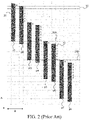
- FIG. 2 and FIG. 3 Examples of print strategies of a 4-pass mode according to the art are shown in FIG. 2 and FIG. 3 .
- the method according to the present invention comprises steps of:
- the printer is able to detect print condition changes. Based on the kind of print condition change a best print strategy is selected that offers the highest print speed while maintain proper print quality. To maintain the print quality a number of print passes per unit area of the recording medium will be unchanged. For example, if the image to be printed was started printing in a 4-pass print mode in the first print strategy, the printer will continue to print in a 4-pass mode in the second print strategy.
- the method comprises the step of selecting the boundary line above a next interweave area of the recording medium in which next interweave area successive print swaths overlap or touch each other in order to create a continuous print.
- the method comprises the step of adapting a distance of a step in the sub-scanning direction in order to position the print head such that a switch from the first print strategy to the second print strategy is possible.
- the distance of the step is smaller than a largest step in the sub-scanning direction according to the second print strategy.
- the print condition detection system is a failure detection system arranged to detect malfunctioning printing elements during printing, and the method comprises the steps of receiving the trigger from the failure detection system that a printing element has started malfunctioning during printing and that the malfunctioning printing element is aligned with another malfunctioning printing element in one of the subsequent scan passes in the main scanning direction, and step d2) comprises the sub-step of selecting the second print strategy in which the malfunctioning printing element is not aligned with the other malfunctioning printing element.
- the method comprises the steps of receiving the trigger from the failure detection system that a malfunctioning printing element has started functioning again, and step d2) comprises the sub-step of selecting the second print strategy to be the print strategy which was in place before receiving the trigger of the malfunctioning printing element.
- the print condition detection system comprises at least one sensor out of a temperature sensor, a pressure sensor and an air humidity sensor, and the method comprises the step of receiving the trigger from the print condition detection system that environmental conditions of the printer are changed which have an impact on the print quality of a printed end product.
- the method comprises the step of receiving the trigger from the print condition detection system of a drift of the recording medium during printing or of a shrinkage of the recording medium.
- the present invention also relates to a digital printer having a print head with an array of printing elements, the print head being arranged to scan a recording medium in a main scanning direction, and the print head and the recording medium being arranged to be moved relative to one another in a sub-scanning direction normal to the main scanning direction in predetermined steps of relatively advancing the recording medium between passes of scanning the recording medium in the main scanning direction, the printer being arranged to operate in a selected print strategy which is characterized by a first pattern of a constant number of scan passes per area unit of the recording medium in which scan passes the array of printing elements moves over the recording medium in the main scanning direction resulting in print swaths on the recording medium, and a constant number of advance steps in the sub-scanning direction, wherein for each of the advance steps a moving distance is prescribed, the digital printer further having an electronic processing unit arranged to control the movements of the print head and the recording medium as well as the operation of the printing elements, the processing system including a print condition detection system arranged to a change of at least
- the print condition detection system is a failure detection system arranged to detect malfunctioning printing elements, characterized in that the processing unit is configured to control the printer in accordance with the method according to the invention.
- the present invention also relates to a software product comprising program code on a machine-readable medium, which program code, when loaded into an electronic processing unit of a digital printer, causes the processing unit to control the printer in accordance with the method according to the invention.
- an ink jet printer comprises a platen 10 which serves for transporting a recording medium (paper) 12 in a sub-scanning direction (arrow A) past a print head unit 14.
- the print head unit 14 is mounted on a carriage 16 that is guided on guide rails 18 and is movable back and forth in a main scanning direction (arrow B) relative to the recording medium 12.
- the print head unit 14 comprises four print heads 20, one for each of the basic colors cyan, magenta, yellow and black.
- Each print head has a linear array of nozzles 22 (printing elements) extending in the sub-scanning direction.
- the nozzles 22 of the print heads 20 can be energized individually to eject ink droplets onto the recording medium 12, thereby to print a pixel on the paper.
- a swath of an image can be printed.
- the number of pixel rows of the swath corresponds to the number of nozzles 22 of each print head.
- the carriage 16 has completed one path, the recording medium 12 is advanced by the width of the swath, so that the next swath can be printed.
- the feed distance of the recording medium will be smaller than the width of the swath, and the pixels and pixel rows printed in different passes may be interleaved.
- the print heads 20 are controlled by a processing unit 24 which processes the print data and generates control signals for controlling the printing elements in the print heads 20 as is well known in the art.
- the processing unit 24 comprises a print condition detection system 24a for detecting a print condition change during printing.
- the print condition detection system 24a is a failure detection system for detecting nozzle failures.
- FIG. 2 and FIG. 3 show different print strategies for a multi-pass print mode according to prior art, i.e. in this example a 4-pass print mode.
- the discussion will be focused on printing in a single color, but is equivalently valid for printing in multiple colors.
- FIG. 2 shows a simplified example of the first print strategy according to the prior art.
- a print head 20 is shown with a linear array of (only) fourteen nozzles.
- the nozzles are fired periodically in order to print an image consisting of a solid image area composed of parallel pixel lines 30.
- Each pixel row 30 is composed of ink dots which are printed in all pixel positions, so that the dots in each row are placed directly adjacent to one another, and the individual pixel rows 30 are also directly adjacent to one another (at least in the respective parts on the recording medium 12 where the print process is completed), so that the image area has a maximum dot coverage (of 100 %).
- FIG. 2 shows a number of eight scan passes p1 - p8 in which the print head 20 moves from left to right and/or from right to left in the main scanning direction (as indicated by a double sided arrow B). Between the scan passes in the main scanning direction B, the print head also moves in the sub-scanning direction (as indicated by the single sided arrow A). The steps of the print head in the sub-scanning direction A are indicated by small downward directed arrows 27. For convenience reasons the distance of each step 27 in the sub-scanning direction A is set equal to the pitch between the nozzles of the print head 20 in the sub-scanning direction A. In practice the step of the print head 20 relative to the recording medium 12 is much larger than the pitch between the nozzles, i.e. the step is equal to a manifold of the pitch between the nozzles.
- a scan pass p1 illustrated in FIG. 2 may be designated as the "first pass", although some of the pixel rows 30 in the top part of the image have been printed already in earlier cycles of the print process.
- FIG. 2 shows a 4-pass print mode. After every scan pass, a swath is completed on the recording medium 12. For example, after the sixth scan pass p6 a swath is completed which is situated between the lines 28A and 28B. The swath width is equal to a seven steps distance in the sub-scanning direction A.
- the shown first print strategy is characterized by a first pattern of a constant number of four scan passes per area unit of the recording medium 12 in which scan passes the array 20 of printing elements moves over the recording medium 12 in the main scanning direction B resulting in print swaths p1 - p8 on the recording medium 12, and a constant number of 4 advance steps in the sub-scanning direction A, wherein for each of the advance steps a moving distance is prescribed.
- the moving distances of the advance steps described for the first print strategy shown in FIG. 2 are respectively 1, 6, 1 and 6 steps.
- the distances of the moving steps may be chosen in such a way that the print quality of the image on the recording medium 12 is assured.
- the process unit 24 of the printer may be configured in such a way that the scan passes p1, p3, p5, p7 are directed from left to right in the main scanning direction B, while the scan passes p2, p4, p6, p8 are directed from right to left in the main scanning direction B, but other configurations of the process unit 24 may be envisioned which lead to other scan directions for the scan passes p1 - p8.
- the scan passes p1 - p8 may also be applied according to an interweave pattern wherein in a subsequent scan pass a part of the nozzles are filling gaps between pixel rows that have been printed in a previous scan pass.
- a swath (consisting of seven pixel rows in this example) of a solid image area is completed as soon as the print head 20 has moved over that swath in four successive passes which constitute one print cycle.
- a nozzle failure in one row can be compensated by activating a nozzle in the other row, provided of course that the nozzle that is needed for the compensation does not fail itself.
- a nozzle failure in a print head for one color is compensated by printing an extra dot in another color.
- FIG. 3 shows a simplified example of the second print strategy according to the prior art.
- the print head 20 is shown with a linear array of (only) fourteen nozzles of which twelve nozzles are actually used in printing the swaths.
- the not used nozzles 31 are grey-shaded.
- a number of eight scan passes r1 - r8 are shown in which the print head 20 moves from left to right and/or from right to left in the main scanning direction (as indicated by a double sided arrow B).
- FIG. 3 also shows a 4-pass print mode. After every scan pass, a swath is completed on the recording medium 12. For example, after the sixth scan pass r6 a swath is completed which is situated between the lines 38A and 38B.
- the swath width is equal to a six steps distance in the sub-scanning direction A.
- the second print strategy is characterized by a second pattern of a constant number of four scan passes per area unit of the recording medium 12 in which scan passes the array 20 of printing elements moves over the recording medium 12 in the main scanning direction B resulting in print swaths r1 - r8 on the recording medium 12, and a constant number of 4 advance steps in the sub-scanning direction A, wherein for each of the advance steps a moving distance is prescribed.
- the moving distances of the advance steps described for the second print strategy shown in FIG. 3 are respectively 2, 4, 2 and 4 steps.
- the distances of the moving steps may be chosen in such a way that the print quality of the image on the recording medium 12 is assured.
- FIG. 4 illustrates a switch of print strategies during printing from the first print strategy shown in FIG. 2 to the second print strategy shown in FIG. 3 .
- the print head 20 is again shown with a linear array of (only) fourteen nozzles of which fourteen nozzles are used in printing the swaths according to the first print strategy and twelve nozzles are used in printing the swaths according to the second print strategy.
- the not used nozzles 31 are grey-shaded.
- a number of fourteen scan passes s1 - s14 are shown in which the print head 20 moves from left to right and/or from right to left in the main scanning direction (as indicated by a double sided arrow B).
- FIG. 4 also shows a 4-pass print mode.
- a swath is completed on the recording medium 12. For example, after the sixth scan pass s6 a swath is completed which is situated between the lines 46A and 46B.
- the swath width is equal to a seven steps distance in the sub-scanning direction A according to the first print strategy.
- the moving distances of the advance steps according to the first print strategy are respectively 1, 6, 1 and 6 steps.
- the moving distances of the advance steps according to the second print strategy are respectively 2, 4, 2 and 4 steps.
- the print condition detection system 24a is a failure detection system for detecting failing nozzles of the print head 20 which is in use in the case presented in FIG. 4 . From the beginning of the passes s1 - s14 there is present a first failing nozzle A which has been detected by the failure detection system 24a before the first pass s1. During the sixth pass s6 a second failing nozzle B is detected by the failure detection system. As can be seen in the pixel row 41 the failing nozzles B and A are going to be aligned in the passes s7 and s8 and also in subsequent passes if there would be no change of print strategy.
- the detection of the second failing nozzle B during the sixth pass s6 is a trigger to change the print strategy during runtime according to the present invention.
- the second print strategy shown in FIG. 3 is selected to replace the first print strategy.
- the nozzles A and B are not aligned anymore which is illustrated in the passes s9 - s14.
- a boundary between the first print strategy and the second print strategy is indicated by the line L.
- the boundary is selected to be a line below the swath at which the second failing nozzle B is detected, i.e. during the sixth pass s6.
- the method according to the invention also works when the boundary is selected to be positioned within the interweave area.
- a media step (6 advance steps) between the sixth pass s6 and seventh pass s7 and a media step (1 advance step) between the seventh pass s7 and the eighth pass s8 are still according to the first print strategy.
- the nozzles of the print head 20 which are positioned above the boundary line L keep printing according to the first print strategy, whereas the nozzles of the print head 20 which are positioned below the boundary line L start printing according to the second print strategy.
- a media step (in this example 3 advance steps) between the eighth pass s8 and the ninth pass s9 is an adaptation step that positions the carriage such that a switch can be made from the first print strategy to the second print strategy.
- the adaptation step is needed to get the bottom of the carriage in proper position to make the switch from the first print strategy to the second print strategy in case of an alignment of failing nozzles.
- Such an adaptation step is typically smaller than the largest step (4 advance steps) of the second print strategy to avoid complexity at the top of a new swath.
- Such a trigger may be for example a trigger from a temperature sensor, a pressure sensor and/or an air humidity sensor of a temperature change, a pressure change and/or an air humidity change respectively, having an impact on the print quality of an end product.
- a nozzle of the print head In the light-green shaded area 43 is printing data according to the second print strategy, but by means of another nozzle number than in the second print strategy.
- a nozzle of the print head in the light-green shaded area 44 is printing data according to the first print strategy, but by means of another nozzle number than in the first print strategy.
- the nozzles that are positioned above the boundary line L keep printing according to the first print strategy, whereas the nozzles that are positioned below the boundary line L start printing according to the second print strategy.
- the eleventh pass s11 and further passes s12 - s14 the media steps follow the second print strategy. In other words, as long as the carriage has not fully passed the boundary line L, the nozzles that re positioned above the boundary line L keep printing according to the first print strategy, whereas the nozzles that are positioned below the boundary line L start printing according to the second print strategy. Once the carriage has fully passed the boundary line L, the switch from the first print strategy to the second print strategy is completed.
- switching between the print strategies is possible at runtime, using a hard split (i.e. boundary line L) between the areas of strategy before and after the switch.
- a hard split i.e. boundary line L
- the switch between the strategies is not reflected in print quality, other than due to the absence of interactions between failing nozzles A, B. Since the first and second strategy produce equivalent print quality due to the same number of passes per swath, both print strategies look the same in normal situations. Therefore the switch between the first and second print strategy is hardly or not noticeable in the end product.
- the average number of steps in during a switch of print strategies may be the same but may also deviate from each other.
- the patterns of media steps, i.e. the media step sizes, in the first and second print strategy are not mandatory and may be chosen in another way in order to avoid alignment of failing nozzles in subsequent passes.
- the selection of the second print strategy is dependent on which nozzle (B in FIG. 4 ) is failing, i.e. the selection of the second print strategy is dependent on print condition information that becomes available only during printing and not before printing is started.
- the method comprises the steps of receiving the trigger from the failure detection system 24a that the malfunctioning nozzle B has started functioning again, and selecting a first print strategy again for further printing.
- FIG. 5 is a flow diagram of the method according to the present invention.
- the method starts in a starting point C leading to a first step S1.
- the print head is starting to move according to the first print strategy.
- step S2 a trigger from the print condition detection system 24a is received by the processing unit 24 that a print condition has changed during printing.
- a third step S3 it is determined if an adaptation of the first print strategy is needed due to the changed print condition. Upon a negative determination the method returns to the first step S1. Upon a positive determination the method proceeds to a fourth step S4.
- step S4 the current scan pass in the main scanning direction B is finished.
- a second print strategy is selected in which the changed printing condition is taken care of, the second print strategy comprising at least one other moving distance for an advance step in the sub-scanning direction A than the first print strategy.
- a boundary line is determined on the recording medium 12 until which the first print strategy is applied and after which the second print strategy is applied.
- the boundary line is determined to be a line on the recording medium 12 below a print swath created by the current scan pass finished in the fourth step S4.
- a seventh step S7 in the next scan passes printing elements 22 of the print head 20 positioned above the boundary line printing according to the first print strategy and printing elements 22 of the print head 20 below the boundary line printing according to the second print strategy.
- a gradual switch from the first print strategy to the second print strategy is performed while the print head 20 is passing the boundary line L in the sub-scanning direction A.
- the method ends in an end point D.
Landscapes
- Engineering & Computer Science (AREA)
- Quality & Reliability (AREA)
- Physics & Mathematics (AREA)
- Mathematical Physics (AREA)
- General Engineering & Computer Science (AREA)
- General Physics & Mathematics (AREA)
- Theoretical Computer Science (AREA)
- Ink Jet (AREA)
Priority Applications (2)
| Application Number | Priority Date | Filing Date | Title |
|---|---|---|---|
| EP20209883.6A EP4005804B1 (fr) | 2020-11-25 | 2020-11-25 | Procédé de commande d'une imprimante numérique avec compensation de défaillance |
| US17/525,168 US11745498B2 (en) | 2020-11-25 | 2021-11-12 | Method of controlling a digital printer with failure compensation |
Applications Claiming Priority (1)
| Application Number | Priority Date | Filing Date | Title |
|---|---|---|---|
| EP20209883.6A EP4005804B1 (fr) | 2020-11-25 | 2020-11-25 | Procédé de commande d'une imprimante numérique avec compensation de défaillance |
Publications (3)
| Publication Number | Publication Date |
|---|---|
| EP4005804A1 true EP4005804A1 (fr) | 2022-06-01 |
| EP4005804B1 EP4005804B1 (fr) | 2025-07-23 |
| EP4005804C0 EP4005804C0 (fr) | 2025-07-23 |
Family
ID=73597992
Family Applications (1)
| Application Number | Title | Priority Date | Filing Date |
|---|---|---|---|
| EP20209883.6A Active EP4005804B1 (fr) | 2020-11-25 | 2020-11-25 | Procédé de commande d'une imprimante numérique avec compensation de défaillance |
Country Status (2)
| Country | Link |
|---|---|
| US (1) | US11745498B2 (fr) |
| EP (1) | EP4005804B1 (fr) |
Citations (3)
| Publication number | Priority date | Publication date | Assignee | Title |
|---|---|---|---|---|
| US6460963B1 (en) * | 1999-03-09 | 2002-10-08 | Seiko Epson Corporation | Bidirectional printing with dot dropout inspection |
| US7104626B2 (en) | 2003-02-26 | 2006-09-12 | Oce-Technologies B.V. | Printing method and printer with failure compensation |
| US20160144613A1 (en) * | 2014-11-25 | 2016-05-26 | Seiko Epson Corporation | Recording method and recording apparatus |
Family Cites Families (5)
| Publication number | Priority date | Publication date | Assignee | Title |
|---|---|---|---|---|
| JP3900896B2 (ja) * | 2001-11-12 | 2007-04-04 | セイコーエプソン株式会社 | プラテンを汚すことなく印刷媒体の端部まで行う印刷 |
| DE602004032369D1 (de) * | 2003-10-31 | 2011-06-01 | Seiko Epson Corp | Druckverfahren und drucksystem |
| US7455378B2 (en) * | 2006-03-16 | 2008-11-25 | Eastman Kodak Company | Printer control system and method for changing print mask height |
| JP5623192B2 (ja) * | 2010-08-31 | 2014-11-12 | キヤノン株式会社 | 画像処理装置および画像処理方法 |
| EP3000602B1 (fr) * | 2014-09-26 | 2020-07-22 | Agfa Nv | Procédé d'éjection à viscosité élevée |
-
2020
- 2020-11-25 EP EP20209883.6A patent/EP4005804B1/fr active Active
-
2021
- 2021-11-12 US US17/525,168 patent/US11745498B2/en active Active
Patent Citations (3)
| Publication number | Priority date | Publication date | Assignee | Title |
|---|---|---|---|---|
| US6460963B1 (en) * | 1999-03-09 | 2002-10-08 | Seiko Epson Corporation | Bidirectional printing with dot dropout inspection |
| US7104626B2 (en) | 2003-02-26 | 2006-09-12 | Oce-Technologies B.V. | Printing method and printer with failure compensation |
| US20160144613A1 (en) * | 2014-11-25 | 2016-05-26 | Seiko Epson Corporation | Recording method and recording apparatus |
Also Published As
| Publication number | Publication date |
|---|---|
| EP4005804B1 (fr) | 2025-07-23 |
| US11745498B2 (en) | 2023-09-05 |
| EP4005804C0 (fr) | 2025-07-23 |
| US20220161550A1 (en) | 2022-05-26 |
Similar Documents
| Publication | Publication Date | Title |
|---|---|---|
| US6942308B2 (en) | Compensation of lateral position changes in printing | |
| JP3245957B2 (ja) | インクジェット記録装置及び記録方法 | |
| JP4434325B2 (ja) | 微小帯状模様を補償するプリント方法 | |
| EP2280831B1 (fr) | Réglage d' une matrice d' impression et d' un substrat dans un dispositif d' impression | |
| US8251477B2 (en) | Multipass printing method | |
| JP4006786B2 (ja) | テスト用ドット記録方法およびプリンタ | |
| US7407251B2 (en) | Printing method, computer-readable medium, printing apparatus, printing system, and pattern for correction | |
| JP5656480B2 (ja) | 記録装置及びその記録位置調整方法 | |
| US20140111815A1 (en) | Printing apparatus and method for correcting print position displacement | |
| JP2001130112A (ja) | ドット間の形成位置ずれを調整する印刷装置 | |
| EP2684700B1 (fr) | Procédé de formation d'un motif d'ajustement d'éjection d'encre, procédé d'ajustement d'éjection d'encre pour tête d'impression à jet d'encre et imprimante à jet d'encre | |
| JP5176846B2 (ja) | 印刷装置および印刷方法 | |
| CN101518995B (zh) | 喷墨打印机 | |
| US20100231644A1 (en) | Liquid ejection apparatus | |
| US7118191B2 (en) | Apparatus and method for ink jet printing using variable interlacing | |
| CN113147178A (zh) | 具有互补不规则边界的拼接条带的打印方法 | |
| US11745498B2 (en) | Method of controlling a digital printer with failure compensation | |
| US6464335B2 (en) | Ink jet printer for reducing dot shift | |
| US20090237740A1 (en) | Method for Obtaining Correction Values and Liquid Ejecting Apparatus | |
| JP5603703B2 (ja) | 記録装置及びその記録位置調整方法 | |
| JP7366590B2 (ja) | 記録装置および記録方法 | |
| JP2003053951A (ja) | プリンタシステム | |
| JP4148279B2 (ja) | テスト用ドット記録方法およびプリンタ | |
| JP3293707B2 (ja) | インクジェット記録装置 | |
| WO2015117925A1 (fr) | Procédé d'impression par jet d'encre et imprimante à jet d'encre |
Legal Events
| Date | Code | Title | Description |
|---|---|---|---|
| PUAI | Public reference made under article 153(3) epc to a published international application that has entered the european phase |
Free format text: ORIGINAL CODE: 0009012 |
|
| STAA | Information on the status of an ep patent application or granted ep patent |
Free format text: STATUS: THE APPLICATION HAS BEEN PUBLISHED |
|
| AK | Designated contracting states |
Kind code of ref document: A1 Designated state(s): AL AT BE BG CH CY CZ DE DK EE ES FI FR GB GR HR HU IE IS IT LI LT LU LV MC MK MT NL NO PL PT RO RS SE SI SK SM TR |
|
| STAA | Information on the status of an ep patent application or granted ep patent |
Free format text: STATUS: REQUEST FOR EXAMINATION WAS MADE |
|
| 17P | Request for examination filed |
Effective date: 20221201 |
|
| RBV | Designated contracting states (corrected) |
Designated state(s): AL AT BE BG CH CY CZ DE DK EE ES FI FR GB GR HR HU IE IS IT LI LT LU LV MC MK MT NL NO PL PT RO RS SE SI SK SM TR |
|
| STAA | Information on the status of an ep patent application or granted ep patent |
Free format text: STATUS: EXAMINATION IS IN PROGRESS |
|
| 17Q | First examination report despatched |
Effective date: 20240730 |
|
| GRAP | Despatch of communication of intention to grant a patent |
Free format text: ORIGINAL CODE: EPIDOSNIGR1 |
|
| STAA | Information on the status of an ep patent application or granted ep patent |
Free format text: STATUS: GRANT OF PATENT IS INTENDED |
|
| RIC1 | Information provided on ipc code assigned before grant |
Ipc: G06K 15/10 20060101ALI20250217BHEP Ipc: B41J 19/14 20060101ALI20250217BHEP Ipc: B41J 2/045 20060101ALI20250217BHEP Ipc: B41J 2/21 20060101AFI20250217BHEP |
|
| INTG | Intention to grant announced |
Effective date: 20250226 |
|
| GRAS | Grant fee paid |
Free format text: ORIGINAL CODE: EPIDOSNIGR3 |
|
| GRAA | (expected) grant |
Free format text: ORIGINAL CODE: 0009210 |
|
| STAA | Information on the status of an ep patent application or granted ep patent |
Free format text: STATUS: THE PATENT HAS BEEN GRANTED |
|
| AK | Designated contracting states |
Kind code of ref document: B1 Designated state(s): AL AT BE BG CH CY CZ DE DK EE ES FI FR GB GR HR HU IE IS IT LI LT LU LV MC MK MT NL NO PL PT RO RS SE SI SK SM TR |
|
| REG | Reference to a national code |
Ref country code: GB Ref legal event code: FG4D |
|
| REG | Reference to a national code |
Ref country code: CH Ref legal event code: EP |
|
| REG | Reference to a national code |
Ref country code: IE Ref legal event code: FG4D |
|
| REG | Reference to a national code |
Ref country code: DE Ref legal event code: R096 Ref document number: 602020054931 Country of ref document: DE |
|
| U01 | Request for unitary effect filed |
Effective date: 20250808 |
|
| U07 | Unitary effect registered |
Designated state(s): AT BE BG DE DK EE FI FR IT LT LU LV MT NL PT RO SE SI Effective date: 20250820 |
|
| U20 | Renewal fee for the european patent with unitary effect paid |
Year of fee payment: 6 Effective date: 20251201 |
|
| PG25 | Lapsed in a contracting state [announced via postgrant information from national office to epo] |
Ref country code: IS Free format text: LAPSE BECAUSE OF FAILURE TO SUBMIT A TRANSLATION OF THE DESCRIPTION OR TO PAY THE FEE WITHIN THE PRESCRIBED TIME-LIMIT Effective date: 20251123 |
|
| PGFP | Annual fee paid to national office [announced via postgrant information from national office to epo] |
Ref country code: GB Payment date: 20251121 Year of fee payment: 6 |
|
| PG25 | Lapsed in a contracting state [announced via postgrant information from national office to epo] |
Ref country code: NO Free format text: LAPSE BECAUSE OF FAILURE TO SUBMIT A TRANSLATION OF THE DESCRIPTION OR TO PAY THE FEE WITHIN THE PRESCRIBED TIME-LIMIT Effective date: 20251023 |
|
| PG25 | Lapsed in a contracting state [announced via postgrant information from national office to epo] |
Ref country code: HR Free format text: LAPSE BECAUSE OF FAILURE TO SUBMIT A TRANSLATION OF THE DESCRIPTION OR TO PAY THE FEE WITHIN THE PRESCRIBED TIME-LIMIT Effective date: 20250723 |
|
| PG25 | Lapsed in a contracting state [announced via postgrant information from national office to epo] |
Ref country code: GR Free format text: LAPSE BECAUSE OF FAILURE TO SUBMIT A TRANSLATION OF THE DESCRIPTION OR TO PAY THE FEE WITHIN THE PRESCRIBED TIME-LIMIT Effective date: 20251024 |
|
| PG25 | Lapsed in a contracting state [announced via postgrant information from national office to epo] |
Ref country code: PL Free format text: LAPSE BECAUSE OF FAILURE TO SUBMIT A TRANSLATION OF THE DESCRIPTION OR TO PAY THE FEE WITHIN THE PRESCRIBED TIME-LIMIT Effective date: 20250723 |
|
| PG25 | Lapsed in a contracting state [announced via postgrant information from national office to epo] |
Ref country code: RS Free format text: LAPSE BECAUSE OF FAILURE TO SUBMIT A TRANSLATION OF THE DESCRIPTION OR TO PAY THE FEE WITHIN THE PRESCRIBED TIME-LIMIT Effective date: 20251023 |
|
| PG25 | Lapsed in a contracting state [announced via postgrant information from national office to epo] |
Ref country code: ES Free format text: LAPSE BECAUSE OF FAILURE TO SUBMIT A TRANSLATION OF THE DESCRIPTION OR TO PAY THE FEE WITHIN THE PRESCRIBED TIME-LIMIT Effective date: 20250723 |
|
| PG25 | Lapsed in a contracting state [announced via postgrant information from national office to epo] |
Ref country code: SM Free format text: LAPSE BECAUSE OF FAILURE TO SUBMIT A TRANSLATION OF THE DESCRIPTION OR TO PAY THE FEE WITHIN THE PRESCRIBED TIME-LIMIT Effective date: 20250723 |
|
| PG25 | Lapsed in a contracting state [announced via postgrant information from national office to epo] |
Ref country code: CZ Free format text: LAPSE BECAUSE OF FAILURE TO SUBMIT A TRANSLATION OF THE DESCRIPTION OR TO PAY THE FEE WITHIN THE PRESCRIBED TIME-LIMIT Effective date: 20250723 |
|
| PG25 | Lapsed in a contracting state [announced via postgrant information from national office to epo] |
Ref country code: SK Free format text: LAPSE BECAUSE OF FAILURE TO SUBMIT A TRANSLATION OF THE DESCRIPTION OR TO PAY THE FEE WITHIN THE PRESCRIBED TIME-LIMIT Effective date: 20250723 |