EP4005824A1 - Motorradreifen - Google Patents
Motorradreifen Download PDFInfo
- Publication number
- EP4005824A1 EP4005824A1 EP21203482.1A EP21203482A EP4005824A1 EP 4005824 A1 EP4005824 A1 EP 4005824A1 EP 21203482 A EP21203482 A EP 21203482A EP 4005824 A1 EP4005824 A1 EP 4005824A1
- Authority
- EP
- European Patent Office
- Prior art keywords
- ply
- belt ply
- band
- angle
- layer
- Prior art date
- Legal status (The legal status is an assumption and is not a legal conclusion. Google has not performed a legal analysis and makes no representation as to the accuracy of the status listed.)
- Granted
Links
Images


Classifications
-
- B—PERFORMING OPERATIONS; TRANSPORTING
- B60—VEHICLES IN GENERAL
- B60C—VEHICLE TYRES; TYRE INFLATION; TYRE CHANGING; CONNECTING VALVES TO INFLATABLE ELASTIC BODIES IN GENERAL; DEVICES OR ARRANGEMENTS RELATED TO TYRES
- B60C9/00—Reinforcements or ply arrangement of pneumatic tyres
- B60C9/18—Structure or arrangement of belts or breakers, crown-reinforcing or cushioning layers
- B60C9/1821—Structure or arrangement of belts or breakers, crown-reinforcing or cushioning layers comprising discrete fibres or filaments
-
- B—PERFORMING OPERATIONS; TRANSPORTING
- B60—VEHICLES IN GENERAL
- B60C—VEHICLE TYRES; TYRE INFLATION; TYRE CHANGING; CONNECTING VALVES TO INFLATABLE ELASTIC BODIES IN GENERAL; DEVICES OR ARRANGEMENTS RELATED TO TYRES
- B60C9/00—Reinforcements or ply arrangement of pneumatic tyres
- B60C9/02—Carcasses
- B60C9/04—Carcasses the reinforcing cords of each carcass ply arranged in a substantially parallel relationship
- B60C9/08—Carcasses the reinforcing cords of each carcass ply arranged in a substantially parallel relationship the cords extend transversely from bead to bead, i.e. radial ply
- B60C9/09—Carcasses the reinforcing cords of each carcass ply arranged in a substantially parallel relationship the cords extend transversely from bead to bead, i.e. radial ply combined with other carcass plies having cords extending diagonally from bead to bead, i.e. combined radial ply and bias angle ply
-
- B—PERFORMING OPERATIONS; TRANSPORTING
- B60—VEHICLES IN GENERAL
- B60C—VEHICLE TYRES; TYRE INFLATION; TYRE CHANGING; CONNECTING VALVES TO INFLATABLE ELASTIC BODIES IN GENERAL; DEVICES OR ARRANGEMENTS RELATED TO TYRES
- B60C9/00—Reinforcements or ply arrangement of pneumatic tyres
- B60C9/18—Structure or arrangement of belts or breakers, crown-reinforcing or cushioning layers
-
- B—PERFORMING OPERATIONS; TRANSPORTING
- B60—VEHICLES IN GENERAL
- B60C—VEHICLE TYRES; TYRE INFLATION; TYRE CHANGING; CONNECTING VALVES TO INFLATABLE ELASTIC BODIES IN GENERAL; DEVICES OR ARRANGEMENTS RELATED TO TYRES
- B60C9/00—Reinforcements or ply arrangement of pneumatic tyres
- B60C9/02—Carcasses
- B60C9/0238—Carcasses characterised by special physical properties of the carcass ply
- B60C2009/0246—Modulus of the ply
-
- B—PERFORMING OPERATIONS; TRANSPORTING
- B60—VEHICLES IN GENERAL
- B60C—VEHICLE TYRES; TYRE INFLATION; TYRE CHANGING; CONNECTING VALVES TO INFLATABLE ELASTIC BODIES IN GENERAL; DEVICES OR ARRANGEMENTS RELATED TO TYRES
- B60C9/00—Reinforcements or ply arrangement of pneumatic tyres
- B60C9/18—Structure or arrangement of belts or breakers, crown-reinforcing or cushioning layers
- B60C9/20—Structure or arrangement of belts or breakers, crown-reinforcing or cushioning layers built-up from rubberised plies each having all cords arranged substantially parallel
- B60C2009/2012—Structure or arrangement of belts or breakers, crown-reinforcing or cushioning layers built-up from rubberised plies each having all cords arranged substantially parallel with particular configuration of the belt cords in the respective belt layers
- B60C2009/2019—Structure or arrangement of belts or breakers, crown-reinforcing or cushioning layers built-up from rubberised plies each having all cords arranged substantially parallel with particular configuration of the belt cords in the respective belt layers comprising cords at an angle of 30 to 60 degrees to the circumferential direction
-
- B—PERFORMING OPERATIONS; TRANSPORTING
- B60—VEHICLES IN GENERAL
- B60C—VEHICLE TYRES; TYRE INFLATION; TYRE CHANGING; CONNECTING VALVES TO INFLATABLE ELASTIC BODIES IN GENERAL; DEVICES OR ARRANGEMENTS RELATED TO TYRES
- B60C9/00—Reinforcements or ply arrangement of pneumatic tyres
- B60C9/18—Structure or arrangement of belts or breakers, crown-reinforcing or cushioning layers
- B60C9/20—Structure or arrangement of belts or breakers, crown-reinforcing or cushioning layers built-up from rubberised plies each having all cords arranged substantially parallel
- B60C2009/2012—Structure or arrangement of belts or breakers, crown-reinforcing or cushioning layers built-up from rubberised plies each having all cords arranged substantially parallel with particular configuration of the belt cords in the respective belt layers
- B60C2009/2022—Structure or arrangement of belts or breakers, crown-reinforcing or cushioning layers built-up from rubberised plies each having all cords arranged substantially parallel with particular configuration of the belt cords in the respective belt layers comprising cords at an angle of 60 to 90 degrees to the circumferential direction
-
- B—PERFORMING OPERATIONS; TRANSPORTING
- B60—VEHICLES IN GENERAL
- B60C—VEHICLE TYRES; TYRE INFLATION; TYRE CHANGING; CONNECTING VALVES TO INFLATABLE ELASTIC BODIES IN GENERAL; DEVICES OR ARRANGEMENTS RELATED TO TYRES
- B60C9/00—Reinforcements or ply arrangement of pneumatic tyres
- B60C9/18—Structure or arrangement of belts or breakers, crown-reinforcing or cushioning layers
- B60C9/20—Structure or arrangement of belts or breakers, crown-reinforcing or cushioning layers built-up from rubberised plies each having all cords arranged substantially parallel
- B60C9/22—Structure or arrangement of belts or breakers, crown-reinforcing or cushioning layers built-up from rubberised plies each having all cords arranged substantially parallel the plies being arranged with all cords disposed along the circumference of the tyre
- B60C2009/2238—Physical properties or dimensions of the ply coating rubber
- B60C2009/2242—Modulus; Hardness; Loss modulus or "tangens delta"
-
- B—PERFORMING OPERATIONS; TRANSPORTING
- B60—VEHICLES IN GENERAL
- B60C—VEHICLE TYRES; TYRE INFLATION; TYRE CHANGING; CONNECTING VALVES TO INFLATABLE ELASTIC BODIES IN GENERAL; DEVICES OR ARRANGEMENTS RELATED TO TYRES
- B60C2200/00—Tyres specially adapted for particular applications
- B60C2200/10—Tyres specially adapted for particular applications for motorcycles, scooters or the like
Definitions
- the present disclosure relates to a motorcycle tire capable of exhibiting excellent turning performance.
- Patent Document 1 discloses a motorcycle tire provided with a tread reinforcing layer composed of two belt plies disposed radially outside the carcass, and one band ply disposed radially outside two belt plies.
- Patent Document 1 Japanese Patent Application Publication No. 2018-111375
- the motorcycle tire of Patent Document 1 generates a large cornering force due to the hoop effect of the two belt plies, and there is a tendency that a force to raise the leant motorcycle becomes large when the centrifugal force is small, for example, from a straight running state to a turning state with small lean angles. Therefore, the motorcycle tire of Patent Document 1 has been desired to have further improvement in turning performance when the centrifugal force is small.
- the present disclosure was made in view of the above circumstances, and a primary object of the present disclosure is to provide a motorcycle tire capable of exhibiting excellent turning performance even when the centrifugal force is small, for example, from a straight running state to a turning state with small lean angles.
- a motorcycle tire comprises a tread portion, a pair of sidewall portions, a pair of bead portions, a carcass extending between the bead portions through the tread portion and the sidewall portions, and a tread reinforcing layer disposed radially outside the carcass in the tread portion, wherein
- the band layer is disposed between the radially inner belt ply and the radially outer belt ply and adjacently to both of the radially inner belt ply and the radially outer belt ply.
- such motorcycle tires can moderate the hoop effect of the radially inner and outer belt plies, and suppress the generation of excessive cornering force when the centrifugal force is small, for example, from a straight running state to a turning state with small lean angles. Therefore, the motorcycle tire according to the present disclosure can exhibit excellent turning performance even when the centrifugal force is small, for example, from a straight running state to a turning state with small lean angles.
- Fig. 1 is a meridian cross-sectional view of a motorcycle tire 1 under its normal state.
- the "normal state” is a state in which the tire 1 is mounted on a normal rim, and inflated to a normal internal pressure, and loaded with no tire load.
- the "normal rim” is a rim specified for the tire in the standard system including the standard on which the tire 1 is based, for example, the "standard rim” in JATMA, "Design Rim” in TRA, and “Measuring Rim” in ETRTO.
- the "normal internal pressure” is the air pressure specified for the tire in the standard system including the standard on which the tire 1 is based, for example, the “maximum air pressure” in JATMA, maximum value described in the table “TIRE LOAD LIMITS AT VARIOUS COLD INFLATION PRESSURES" in TRA, and "INFLATION PRESSURE” in ETRTO.
- the tire 1 in the present embodiment comprises a tread portion 2, a pair of sidewall portions 3 extending radially inwardly from respective tread edges of the tread portion 2, and a pair of bead portions 4 located at radially inner ends of the respective sidewall portions 3.
- a bead core 5 is embedded in this embodiment.
- the tread surface 2s which is the radially outer surface of the tread portion 2, extends from one to the other of the tread edges Te through the tire equator C, while curving convexly toward the radial outside, for example, in an arc shape.
- the tire 1 is therefore, possible to make turn with a large camber angle.
- the maximum tire cross-section width occurs between the tread edges Te.
- the tread edges Te are the ends in the tire axial direction of the tread portion 2.
- the tire equator C is the center in the tire axial direction between the tread edges Te.
- the length measured along the tread surface 2s between the tread edges Tes is the developed tread width Twe.
- the tire 1 in the present embodiment comprises a carcass 6 extending between the bead portions 4 through the tread portion 2 and the sidewall portions 3.
- the carcass 6 is turned up in each bead portion 4 around a bead core 5 disposed therein so that the carcass 6 comprises a pair of turned-up portions 6b and a main portion 6a therebetween.
- the carcass 6 comprises at least one carcass ply, in this embodiment two carcass plies 6A and 6B.
- Each of the carcass plies 6A and 6B comprises, for example, carcass cords arranged at an angle in a range from 75 to 90 degrees with respect to the tire circumferential direction.
- the tire 1 in the present embodiment is provided with a tread reinforcing layer 7 disposed radially outside the carcass 6 in the tread portion 2.
- the tread reinforcing layer 7 in the present embodiment includes a belt layer 8 and a band layer 9.
- Fig. 2 is a developed view of the tread reinforcing layer 7 in the present embodiment.
- the belt layer 8 is an array of a plurality of belt cords 8a as shown in Figs. 1 and 2
- the band layer 9 is an array of a plurality of band codes 9a.
- the belt layer 8 in the present embodiment comprises one radially inner belt ply 8A disposed adjacently to the carcass 6, and one radially outer belt ply 8B disposed radially outside the radially inner belt ply 8A.
- the radially inner belt ply 8A in the present embodiment is formed from the belt cords 8a arranged at a first angle ⁇ 1 with respect to the tire circumferential direction.
- the radially outer belt ply 8B in the present embodiment is formed from the belt cords 8b arranged at a second angle ⁇ 2 different from the first angle ⁇ 1.
- Such belt layer 8 is useful for improving the rigidity of the tread portion 2 and generating a large cornering force by the hoop effect of the radially inner belt ply 8A and the radially outer belt ply 8B.
- the turning of the motorcycle is performed by leaning the motorcycle.
- the lateral force on the tire 1 is expressed as the sum of the camber thrust generated by the leaning of the tire 1 and the cornering force generated by the slip angle of the tire 1.
- the motorcycle can turn stably and thus can be said to be excellent in the turning performance or cornering performance.
- the centrifugal force of a motorcycle is relatively small from straight running to turning with small lean angles, and becomes larger during cornering with large lean angles. Therefore, by suppressing the generation of the cornering force from the straight running to the turning with small lean angles, and increasing the cornering force during cornering with large lean angles, it is possible to improve the turning/cornering performance of the tire 1.
- the cornering force is increased by the belt layer 8, therefore, the lateral force acting on the tire 1 is also increased.
- the centrifugal force is large such as during cornering with large lean angles.
- the band layer 9 is composed of at least one, in the present embodiment only one band ply 9A of made of band cords 9a arranged at an angle of 5 degrees or less with respect to the tire circumferential direction.
- the band ply 9A is disposed between the radially inner belt ply 8A and the radially outer belt ply 8B, and adjacently to the radially inner belt ply 8A and the radially outer belt ply 8B.
- the hoop effect by the radially inner belt ply 8A and the radially outer belt ply 8B can be alleviated, and it is possible to suppress the generation of excessive cornering force when the centrifugal force is small such as from a straight running state to a turning state with small lean angles. Therefore, the tire 1 in the present embodiment can exhibit excellent turning performance even when the centrifugal force is small such as from a straight running state to a turning state with small lean angles.
- the developed width W1 of the band ply 9A is smaller than the developed width w2 of the radially inner belt ply 8A and the developed width w3 of the radially outer belt ply 8B.
- such tread reinforcing layer 7 can moderate the hoop effect of the radially inner belt ply 8A and the radially outer belt ply 8B from a straight running state to a turning state with small lean angles, and can exert the hoop effect in a turning state with large lean angles.
- the tire 1 in the present embodiment can suppress the generation of an excessive cornering force from a straight running state to a turning state with small lean angles, and can generate a large cornering force in a turning state with large lean angles.
- the turning/cornering performance from a straight running state to a turning state with large lean angles can be improved.
- the developed width w1 of the band ply 9A is preferably 30% to 90% of the developed tread width TWe.
- the developed width W1 of the band ply 9A is 30% or more of the developed tread width TWe, even if the tread portion 2 is deformed during braking in a straight-running state, the band ply 9A can surely locate within the ground contact patch, and the cornering force can be reduced.
- the tire 1 in the present embodiment can surely improve the turning/cornering performance from the straight running state to the turning state with large lean angles.
- the developed width w2 of the radially inner belt ply 8A is preferably set in a range from 90% to 100% of the developed tread width TWe.
- the developed width W3 of the radially outer belt ply 8B is preferably set in a range from 85% to 95% of the developed tread width TWe.
- the developed width W3 of the radially outer belt ply 8B in the present embodiment is smaller than the developed width w2 of the radially inner belt ply 8A. such belt layer 8 can further improve the rigidity of the tread portion 2.
- the first angle ⁇ 1 of the belt cords 8a of the radially inner belt ply 8A with respect to the tire circumferential direction is preferably set in a range from 50 to 80 degrees.
- the first angle ⁇ 1 is 50 degrees or more, it is possible to suppress an excessive hoop effect, and generate a good cornering force, and improve the turning performance.
- the first angle ⁇ 1 is 80 degrees or less, an angle difference can be surely provided between the belt cords 8a of the radially outer belt ply 8B and the belt cords 8a of the radially inner belt ply 8A, and the hoop effect can be enhanced.
- the second angle ⁇ 2 of the belt cords 8a of the radially outer belt ply 8B with respect to the tire circumferential direction is preferably set in a range from 70 to 90 degrees.
- the second angle ⁇ 2 is 70 degrees or more, it is possible to suppress an excessive hoop effect, and generate a good cornering force, and improve the turning performance.
- the direction of inclination is the same as that of the belt cords 8a of the radially inner belt ply 8A so that an arrangement error during manufacturing can be reduced.
- ) between the second angle ⁇ 2 and the first angle ⁇ 1 is preferably set in a range from 10 to 40 degrees.
- ) is 10 degrees or more, the hoop effect of the radially inner belt ply 8A and the radially outer belt ply 8B can be exhibited.
- ) is 40 degrees or less, it is possible to reduce the difference in the magnitude of the cornering force between the presence and absence of the band ply 9A, and improve the transient characteristics at the boundary position of the band ply 9A.
- the second angle ⁇ 2 in the present embodiment is larger than the first angle ⁇ 1.
- the rigidity of the tread portion 2 can be improved which helps to generate a larger cornering force.
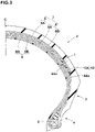
- Fig. 3 is a cross-sectional view of the tread portion 2 in the present embodiment.
- the tread portion 2 in the present embodiment comprises a rubber layer 10 disposed on the axially outer side of the band ply 9A.
- the rubber layer 10 is disposed on each side of the band ply 9A in the tire axial direction.
- Each of the rubber layers 10 is composed of at least one, in this embodiment, only one rubber sheet 10A.
- the state in which the rubber layer 10 composed of the rubber sheet 10A is included means such a state that the distance between members which are arranged so as to sandwich the rubber layer 10 is kept substantially constant.
- a substantially constant distance means that the variation with respect to the average value of the distance is within +- 15%.
- tread portion 2 is improved in torsional rigidity by the rubber sheet 10A, and can increase the cornering force during cornering with large lean angles.
- the tire 1 in the present embodiment can improve the turning performance during cornering with large lean angles.
- the rubber layer 10 is composed of a plurality of rubber sheets 10A
- the rubber sheets 10A may be arranged in the tire radial direction in piles, or the rubber sheets 10A may be arranged in the tire axial direction side-by-side.
- the rubber layer 10 in the present embodiment is arranged between the radially inner belt ply 8A and the radially outer belt ply 8B.
- the distance "t" between the radially inner belt ply 8A and the radially outer belt ply 8B measured at the position where the rubber layer 10 is arranged, is preferably 0.5 to 3.0 mm and substantially constant.
- the distance "t" between the radially inner belt ply 8A and the radially outer belt ply 8B is the shortest distance between the radially outer surface 8As of the radially inner belt ply 8A and the radially inner surface 8Bs of the radially outer belt ply 8B.
- the sum (W1 + W4 ⁇ 2) of the developed width W1 of the band ply 9A and the developed width W4 of the rubber layers 10 on both sides is smaller than the developed width W2 of the radially inner belt ply 8A, but larger than the developed width W3 of the radially outer belt ply 8B.
- such rubber layer 10 can further improve the torsional rigidity of the tread portion 2.
- the complex elastic modulus G* of the rubber layer 10 at 70 degrees C. is preferably 500 kPa or more.
- Such rubber layer 10 more reliably exert the twisting effect and increase the cornering force in a turning state with large lean angles.
- the complex elastic modulus G* of the rubber layer 10 at 70 degrees C. is measured according to Japanese Industrial Standard JIS-K6394 under the following conditions, for example, using a dynamic viscoelasticity measuring device (EPLEXOR series) manufactured by GABO.
- EPLEXOR series dynamic viscoelasticity measuring device manufactured by GABO.
- test tires were mounted on the front and rear wheels of a large-size motorcycle, and tested for the moderate turning performance from the upright state to the turning state with small lean angles, the steep cornering performance during cornering with large lean angles, and the transient characteristics from the moderate turning state to the steep cornering state. These performances and transient characteristics were evaluated by the test rider.
- the working example tires were improved in moderate turning performance while maintaining the steep cornering performance.
- the tires according to the present disclosure can exhibit good turning performance even when the centrifugal force is small, for example, from the straight running state to the moderate turning state.
Landscapes
- Engineering & Computer Science (AREA)
- Mechanical Engineering (AREA)
- Tires In General (AREA)
Applications Claiming Priority (1)
| Application Number | Priority Date | Filing Date | Title |
|---|---|---|---|
| JP2020195351A JP7615633B2 (ja) | 2020-11-25 | 2020-11-25 | 自動二輪車用タイヤ |
Publications (2)
| Publication Number | Publication Date |
|---|---|
| EP4005824A1 true EP4005824A1 (de) | 2022-06-01 |
| EP4005824B1 EP4005824B1 (de) | 2023-07-12 |
Family
ID=78516538
Family Applications (1)
| Application Number | Title | Priority Date | Filing Date |
|---|---|---|---|
| EP21203482.1A Active EP4005824B1 (de) | 2020-11-25 | 2021-10-19 | Motorradreifen |
Country Status (4)
| Country | Link |
|---|---|
| US (1) | US20220161600A1 (de) |
| EP (1) | EP4005824B1 (de) |
| JP (1) | JP7615633B2 (de) |
| CN (1) | CN114537048B (de) |
Cited By (1)
| Publication number | Priority date | Publication date | Assignee | Title |
|---|---|---|---|---|
| EP4253087B1 (de) * | 2022-03-28 | 2025-06-04 | Sumitomo Rubber Industries, Ltd. | Motorradreifen |
Families Citing this family (1)
| Publication number | Priority date | Publication date | Assignee | Title |
|---|---|---|---|---|
| JP2023183269A (ja) * | 2022-06-15 | 2023-12-27 | 住友ゴム工業株式会社 | 自動二輪車用タイヤ |
Citations (5)
| Publication number | Priority date | Publication date | Assignee | Title |
|---|---|---|---|---|
| US5441093A (en) * | 1990-06-27 | 1995-08-15 | Sumitomo Rubber Industries, Ltd. | Motorcycle radial tire with folded breaker ply and spirally wound band ply |
| EP1242252B1 (de) * | 1999-12-21 | 2003-11-26 | THE GOODYEAR TIRE & RUBBER COMPANY | Verstärkungsgürtel-paket für reifen |
| US20070113946A1 (en) * | 2005-11-22 | 2007-05-24 | Sumitomo Rubber Industries, Ltd. | Heavy duty radial tire |
| JP2018111375A (ja) | 2017-01-11 | 2018-07-19 | 住友ゴム工業株式会社 | 自動二輪車用タイヤ |
| FR3084014A3 (fr) * | 2018-07-19 | 2020-01-24 | Michelin & Cie | Pneumatique avec un sommet comportant une couche de rigidification et une bande de roulement a forte adherence |
Family Cites Families (21)
| Publication number | Priority date | Publication date | Assignee | Title |
|---|---|---|---|---|
| JP2702835B2 (ja) * | 1990-10-29 | 1998-01-26 | 住友ゴム工業株式会社 | 自動二輪車用ラジアルタイヤ |
| JPH06286417A (ja) * | 1993-03-31 | 1994-10-11 | Bridgestone Corp | 空気入りタイヤ |
| US5605589A (en) * | 1995-03-06 | 1997-02-25 | The Goodyear Tire & Rubber Company | Pneumatic tire with specified spacing between cords of inner and outer belts |
| JP2001253207A (ja) * | 2000-03-09 | 2001-09-18 | Bridgestone Corp | 空気入りタイヤ |
| JP4377110B2 (ja) * | 2002-06-28 | 2009-12-02 | 株式会社ブリヂストン | 空気入りタイヤ |
| US20040163748A1 (en) * | 2003-02-24 | 2004-08-26 | Kiyoshi Ueyoko | Tire having a composite belt structure |
| US8505601B2 (en) * | 2005-05-31 | 2013-08-13 | The Yokohama Rubber Co., Ltd. | Pneumatic radial tire |
| WO2007058116A1 (ja) * | 2005-11-18 | 2007-05-24 | Bridgestone Corporation | 自動二輪車用ラジアルタイヤ |
| JP4758764B2 (ja) * | 2005-12-28 | 2011-08-31 | 住友ゴム工業株式会社 | 重荷重用ラジアルタイヤ |
| JP2007283802A (ja) * | 2006-04-12 | 2007-11-01 | Bridgestone Corp | 二輪車用空気入りタイヤ |
| JP2008162448A (ja) * | 2006-12-28 | 2008-07-17 | Bridgestone Corp | 自動二輪車用空気入りタイヤ |
| JP2010120436A (ja) * | 2008-11-17 | 2010-06-03 | Bridgestone Corp | 自動二輪車用空気入りタイヤ |
| JP5327957B2 (ja) * | 2008-11-21 | 2013-10-30 | 株式会社ブリヂストン | 自動二輪車用空気入りタイヤ |
| FR2939721B1 (fr) * | 2008-12-17 | 2010-12-31 | Michelin Soc Tech | Pneumatique pour vehicules a carcasse interrompue et comportant une couche d'elements de renforcement circonferentiels |
| JP2010260417A (ja) * | 2009-04-30 | 2010-11-18 | Bridgestone Corp | 空気入りタイヤ |
| JP2013180703A (ja) * | 2012-03-02 | 2013-09-12 | Bridgestone Corp | 自動二輪車用空気入りタイヤ |
| WO2014010352A1 (ja) * | 2012-07-13 | 2014-01-16 | 横浜ゴム株式会社 | 空気入りタイヤ |
| JP2015116893A (ja) * | 2013-12-17 | 2015-06-25 | 住友ゴム工業株式会社 | 自動二輪車用タイヤ |
| US10336139B2 (en) * | 2014-02-27 | 2019-07-02 | Compagnie Generale Des Etablissements Michelin | Body ply shape for a tire |
| JP6331606B2 (ja) * | 2014-04-04 | 2018-05-30 | 横浜ゴム株式会社 | 空気入りタイヤ |
| JP2018039334A (ja) * | 2016-09-06 | 2018-03-15 | 住友ゴム工業株式会社 | 二輪自動車用タイヤ |
-
2020
- 2020-11-25 JP JP2020195351A patent/JP7615633B2/ja active Active
-
2021
- 2021-10-19 EP EP21203482.1A patent/EP4005824B1/de active Active
- 2021-11-09 CN CN202111319234.9A patent/CN114537048B/zh active Active
- 2021-11-10 US US17/523,254 patent/US20220161600A1/en not_active Abandoned
Patent Citations (5)
| Publication number | Priority date | Publication date | Assignee | Title |
|---|---|---|---|---|
| US5441093A (en) * | 1990-06-27 | 1995-08-15 | Sumitomo Rubber Industries, Ltd. | Motorcycle radial tire with folded breaker ply and spirally wound band ply |
| EP1242252B1 (de) * | 1999-12-21 | 2003-11-26 | THE GOODYEAR TIRE & RUBBER COMPANY | Verstärkungsgürtel-paket für reifen |
| US20070113946A1 (en) * | 2005-11-22 | 2007-05-24 | Sumitomo Rubber Industries, Ltd. | Heavy duty radial tire |
| JP2018111375A (ja) | 2017-01-11 | 2018-07-19 | 住友ゴム工業株式会社 | 自動二輪車用タイヤ |
| FR3084014A3 (fr) * | 2018-07-19 | 2020-01-24 | Michelin & Cie | Pneumatique avec un sommet comportant une couche de rigidification et une bande de roulement a forte adherence |
Cited By (1)
| Publication number | Priority date | Publication date | Assignee | Title |
|---|---|---|---|---|
| EP4253087B1 (de) * | 2022-03-28 | 2025-06-04 | Sumitomo Rubber Industries, Ltd. | Motorradreifen |
Also Published As
| Publication number | Publication date |
|---|---|
| CN114537048B (zh) | 2025-12-05 |
| EP4005824B1 (de) | 2023-07-12 |
| JP7615633B2 (ja) | 2025-01-17 |
| CN114537048A (zh) | 2022-05-27 |
| JP2022083810A (ja) | 2022-06-06 |
| US20220161600A1 (en) | 2022-05-26 |
Similar Documents
| Publication | Publication Date | Title |
|---|---|---|
| US11331963B2 (en) | Run-flat tire | |
| EP2724871B1 (de) | Personenkraftwagen | |
| US8925599B2 (en) | Heavy duty tire | |
| EP2990225A1 (de) | Luftreifen | |
| US11254167B2 (en) | Pneumatic tyre | |
| US11780268B2 (en) | Tyre | |
| EP4005824B1 (de) | Motorradreifen | |
| EP2261060B1 (de) | Motorradreifen | |
| EP3925794B1 (de) | Luftreifen | |
| EP4253087B1 (de) | Motorradreifen | |
| JP7230479B2 (ja) | 二輪自動車用タイヤ | |
| EP3895916B1 (de) | Luftreifen | |
| JP6825475B2 (ja) | 二輪自動車用タイヤ | |
| EP4292834B1 (de) | Motorradreifen | |
| US12030347B2 (en) | Motorcycle tire set | |
| EP3944967B1 (de) | Motorradreifen | |
| EP4005823B1 (de) | Diagonalreifen für zweiradfahrzeuge | |
| JP7472527B2 (ja) | 二輪車用バイアスタイヤ | |
| EP3521061B1 (de) | Reifen | |
| JP2023096719A (ja) | 自動二輪車用タイヤ |
Legal Events
| Date | Code | Title | Description |
|---|---|---|---|
| PUAI | Public reference made under article 153(3) epc to a published international application that has entered the european phase |
Free format text: ORIGINAL CODE: 0009012 |
|
| STAA | Information on the status of an ep patent application or granted ep patent |
Free format text: STATUS: THE APPLICATION HAS BEEN PUBLISHED |
|
| AK | Designated contracting states |
Kind code of ref document: A1 Designated state(s): AL AT BE BG CH CY CZ DE DK EE ES FI FR GB GR HR HU IE IS IT LI LT LU LV MC MK MT NL NO PL PT RO RS SE SI SK SM TR |
|
| STAA | Information on the status of an ep patent application or granted ep patent |
Free format text: STATUS: REQUEST FOR EXAMINATION WAS MADE |
|
| 17P | Request for examination filed |
Effective date: 20220801 |
|
| RBV | Designated contracting states (corrected) |
Designated state(s): AL AT BE BG CH CY CZ DE DK EE ES FI FR GB GR HR HU IE IS IT LI LT LU LV MC MK MT NL NO PL PT RO RS SE SI SK SM TR |
|
| RIC1 | Information provided on ipc code assigned before grant |
Ipc: B60C 9/22 20060101ALI20230324BHEP Ipc: B60C 9/20 20060101ALI20230324BHEP Ipc: B60C 9/18 20060101AFI20230324BHEP |
|
| GRAP | Despatch of communication of intention to grant a patent |
Free format text: ORIGINAL CODE: EPIDOSNIGR1 |
|
| STAA | Information on the status of an ep patent application or granted ep patent |
Free format text: STATUS: GRANT OF PATENT IS INTENDED |
|
| GRAS | Grant fee paid |
Free format text: ORIGINAL CODE: EPIDOSNIGR3 |
|
| INTG | Intention to grant announced |
Effective date: 20230512 |
|
| GRAA | (expected) grant |
Free format text: ORIGINAL CODE: 0009210 |
|
| STAA | Information on the status of an ep patent application or granted ep patent |
Free format text: STATUS: THE PATENT HAS BEEN GRANTED |
|
| AK | Designated contracting states |
Kind code of ref document: B1 Designated state(s): AL AT BE BG CH CY CZ DE DK EE ES FI FR GB GR HR HU IE IS IT LI LT LU LV MC MK MT NL NO PL PT RO RS SE SI SK SM TR |
|
| REG | Reference to a national code |
Ref country code: CH Ref legal event code: EP |
|
| REG | Reference to a national code |
Ref country code: IE Ref legal event code: FG4D |
|
| REG | Reference to a national code |
Ref country code: DE Ref legal event code: R096 Ref document number: 602021003424 Country of ref document: DE |
|
| REG | Reference to a national code |
Ref country code: LT Ref legal event code: MG9D |
|
| REG | Reference to a national code |
Ref country code: NL Ref legal event code: MP Effective date: 20230712 |
|
| REG | Reference to a national code |
Ref country code: AT Ref legal event code: MK05 Ref document number: 1586751 Country of ref document: AT Kind code of ref document: T Effective date: 20230712 |
|
| PG25 | Lapsed in a contracting state [announced via postgrant information from national office to epo] |
Ref country code: NL Free format text: LAPSE BECAUSE OF FAILURE TO SUBMIT A TRANSLATION OF THE DESCRIPTION OR TO PAY THE FEE WITHIN THE PRESCRIBED TIME-LIMIT Effective date: 20230712 |
|
| PG25 | Lapsed in a contracting state [announced via postgrant information from national office to epo] |
Ref country code: GR Free format text: LAPSE BECAUSE OF FAILURE TO SUBMIT A TRANSLATION OF THE DESCRIPTION OR TO PAY THE FEE WITHIN THE PRESCRIBED TIME-LIMIT Effective date: 20231013 |
|
| PG25 | Lapsed in a contracting state [announced via postgrant information from national office to epo] |
Ref country code: ES Free format text: LAPSE BECAUSE OF FAILURE TO SUBMIT A TRANSLATION OF THE DESCRIPTION OR TO PAY THE FEE WITHIN THE PRESCRIBED TIME-LIMIT Effective date: 20230712 |
|
| PG25 | Lapsed in a contracting state [announced via postgrant information from national office to epo] |
Ref country code: IS Free format text: LAPSE BECAUSE OF FAILURE TO SUBMIT A TRANSLATION OF THE DESCRIPTION OR TO PAY THE FEE WITHIN THE PRESCRIBED TIME-LIMIT Effective date: 20231112 |
|
| PG25 | Lapsed in a contracting state [announced via postgrant information from national office to epo] |
Ref country code: SE Free format text: LAPSE BECAUSE OF FAILURE TO SUBMIT A TRANSLATION OF THE DESCRIPTION OR TO PAY THE FEE WITHIN THE PRESCRIBED TIME-LIMIT Effective date: 20230712 Ref country code: RS Free format text: LAPSE BECAUSE OF FAILURE TO SUBMIT A TRANSLATION OF THE DESCRIPTION OR TO PAY THE FEE WITHIN THE PRESCRIBED TIME-LIMIT Effective date: 20230712 Ref country code: PT Free format text: LAPSE BECAUSE OF FAILURE TO SUBMIT A TRANSLATION OF THE DESCRIPTION OR TO PAY THE FEE WITHIN THE PRESCRIBED TIME-LIMIT Effective date: 20231113 Ref country code: NO Free format text: LAPSE BECAUSE OF FAILURE TO SUBMIT A TRANSLATION OF THE DESCRIPTION OR TO PAY THE FEE WITHIN THE PRESCRIBED TIME-LIMIT Effective date: 20231012 Ref country code: LV Free format text: LAPSE BECAUSE OF FAILURE TO SUBMIT A TRANSLATION OF THE DESCRIPTION OR TO PAY THE FEE WITHIN THE PRESCRIBED TIME-LIMIT Effective date: 20230712 Ref country code: LT Free format text: LAPSE BECAUSE OF FAILURE TO SUBMIT A TRANSLATION OF THE DESCRIPTION OR TO PAY THE FEE WITHIN THE PRESCRIBED TIME-LIMIT Effective date: 20230712 Ref country code: IS Free format text: LAPSE BECAUSE OF FAILURE TO SUBMIT A TRANSLATION OF THE DESCRIPTION OR TO PAY THE FEE WITHIN THE PRESCRIBED TIME-LIMIT Effective date: 20231112 Ref country code: HR Free format text: LAPSE BECAUSE OF FAILURE TO SUBMIT A TRANSLATION OF THE DESCRIPTION OR TO PAY THE FEE WITHIN THE PRESCRIBED TIME-LIMIT Effective date: 20230712 Ref country code: GR Free format text: LAPSE BECAUSE OF FAILURE TO SUBMIT A TRANSLATION OF THE DESCRIPTION OR TO PAY THE FEE WITHIN THE PRESCRIBED TIME-LIMIT Effective date: 20231013 Ref country code: FI Free format text: LAPSE BECAUSE OF FAILURE TO SUBMIT A TRANSLATION OF THE DESCRIPTION OR TO PAY THE FEE WITHIN THE PRESCRIBED TIME-LIMIT Effective date: 20230712 Ref country code: ES Free format text: LAPSE BECAUSE OF FAILURE TO SUBMIT A TRANSLATION OF THE DESCRIPTION OR TO PAY THE FEE WITHIN THE PRESCRIBED TIME-LIMIT Effective date: 20230712 Ref country code: AT Free format text: LAPSE BECAUSE OF FAILURE TO SUBMIT A TRANSLATION OF THE DESCRIPTION OR TO PAY THE FEE WITHIN THE PRESCRIBED TIME-LIMIT Effective date: 20230712 |
|
| PG25 | Lapsed in a contracting state [announced via postgrant information from national office to epo] |
Ref country code: PL Free format text: LAPSE BECAUSE OF FAILURE TO SUBMIT A TRANSLATION OF THE DESCRIPTION OR TO PAY THE FEE WITHIN THE PRESCRIBED TIME-LIMIT Effective date: 20230712 |
|
| REG | Reference to a national code |
Ref country code: DE Ref legal event code: R097 Ref document number: 602021003424 Country of ref document: DE |
|
| PG25 | Lapsed in a contracting state [announced via postgrant information from national office to epo] |
Ref country code: SM Free format text: LAPSE BECAUSE OF FAILURE TO SUBMIT A TRANSLATION OF THE DESCRIPTION OR TO PAY THE FEE WITHIN THE PRESCRIBED TIME-LIMIT Effective date: 20230712 Ref country code: RO Free format text: LAPSE BECAUSE OF FAILURE TO SUBMIT A TRANSLATION OF THE DESCRIPTION OR TO PAY THE FEE WITHIN THE PRESCRIBED TIME-LIMIT Effective date: 20230712 Ref country code: EE Free format text: LAPSE BECAUSE OF FAILURE TO SUBMIT A TRANSLATION OF THE DESCRIPTION OR TO PAY THE FEE WITHIN THE PRESCRIBED TIME-LIMIT Effective date: 20230712 Ref country code: DK Free format text: LAPSE BECAUSE OF FAILURE TO SUBMIT A TRANSLATION OF THE DESCRIPTION OR TO PAY THE FEE WITHIN THE PRESCRIBED TIME-LIMIT Effective date: 20230712 Ref country code: CZ Free format text: LAPSE BECAUSE OF FAILURE TO SUBMIT A TRANSLATION OF THE DESCRIPTION OR TO PAY THE FEE WITHIN THE PRESCRIBED TIME-LIMIT Effective date: 20230712 Ref country code: SK Free format text: LAPSE BECAUSE OF FAILURE TO SUBMIT A TRANSLATION OF THE DESCRIPTION OR TO PAY THE FEE WITHIN THE PRESCRIBED TIME-LIMIT Effective date: 20230712 |
|
| PLBE | No opposition filed within time limit |
Free format text: ORIGINAL CODE: 0009261 |
|
| STAA | Information on the status of an ep patent application or granted ep patent |
Free format text: STATUS: NO OPPOSITION FILED WITHIN TIME LIMIT |
|
| PG25 | Lapsed in a contracting state [announced via postgrant information from national office to epo] |
Ref country code: IT Free format text: LAPSE BECAUSE OF FAILURE TO SUBMIT A TRANSLATION OF THE DESCRIPTION OR TO PAY THE FEE WITHIN THE PRESCRIBED TIME-LIMIT Effective date: 20230712 Ref country code: MC Free format text: LAPSE BECAUSE OF FAILURE TO SUBMIT A TRANSLATION OF THE DESCRIPTION OR TO PAY THE FEE WITHIN THE PRESCRIBED TIME-LIMIT Effective date: 20230712 |
|
| REG | Reference to a national code |
Ref country code: BE Ref legal event code: MM Effective date: 20231031 |
|
| 26N | No opposition filed |
Effective date: 20240415 |
|
| PG25 | Lapsed in a contracting state [announced via postgrant information from national office to epo] |
Ref country code: LU Free format text: LAPSE BECAUSE OF NON-PAYMENT OF DUE FEES Effective date: 20231019 |
|
| PG25 | Lapsed in a contracting state [announced via postgrant information from national office to epo] |
Ref country code: LU Free format text: LAPSE BECAUSE OF NON-PAYMENT OF DUE FEES Effective date: 20231019 |
|
| PG25 | Lapsed in a contracting state [announced via postgrant information from national office to epo] |
Ref country code: SI Free format text: LAPSE BECAUSE OF FAILURE TO SUBMIT A TRANSLATION OF THE DESCRIPTION OR TO PAY THE FEE WITHIN THE PRESCRIBED TIME-LIMIT Effective date: 20230712 |
|
| PG25 | Lapsed in a contracting state [announced via postgrant information from national office to epo] |
Ref country code: BE Free format text: LAPSE BECAUSE OF NON-PAYMENT OF DUE FEES Effective date: 20231031 |
|
| PG25 | Lapsed in a contracting state [announced via postgrant information from national office to epo] |
Ref country code: IE Free format text: LAPSE BECAUSE OF NON-PAYMENT OF DUE FEES Effective date: 20231019 |
|
| PG25 | Lapsed in a contracting state [announced via postgrant information from national office to epo] |
Ref country code: IE Free format text: LAPSE BECAUSE OF NON-PAYMENT OF DUE FEES Effective date: 20231019 |
|
| PG25 | Lapsed in a contracting state [announced via postgrant information from national office to epo] |
Ref country code: BG Free format text: LAPSE BECAUSE OF FAILURE TO SUBMIT A TRANSLATION OF THE DESCRIPTION OR TO PAY THE FEE WITHIN THE PRESCRIBED TIME-LIMIT Effective date: 20230712 |
|
| P01 | Opt-out of the competence of the unified patent court (upc) registered |
Free format text: CASE NUMBER: UPC_APP_118628/2023 Effective date: 20230510 |
|
| PG25 | Lapsed in a contracting state [announced via postgrant information from national office to epo] |
Ref country code: BG Free format text: LAPSE BECAUSE OF FAILURE TO SUBMIT A TRANSLATION OF THE DESCRIPTION OR TO PAY THE FEE WITHIN THE PRESCRIBED TIME-LIMIT Effective date: 20230712 |
|
| REG | Reference to a national code |
Ref country code: CH Ref legal event code: PL |
|
| PG25 | Lapsed in a contracting state [announced via postgrant information from national office to epo] |
Ref country code: CH Free format text: LAPSE BECAUSE OF NON-PAYMENT OF DUE FEES Effective date: 20241031 |
|
| PG25 | Lapsed in a contracting state [announced via postgrant information from national office to epo] |
Ref country code: CY Free format text: LAPSE BECAUSE OF FAILURE TO SUBMIT A TRANSLATION OF THE DESCRIPTION OR TO PAY THE FEE WITHIN THE PRESCRIBED TIME-LIMIT; INVALID AB INITIO Effective date: 20211019 |
|
| PGFP | Annual fee paid to national office [announced via postgrant information from national office to epo] |
Ref country code: FR Payment date: 20250908 Year of fee payment: 5 |
|
| PG25 | Lapsed in a contracting state [announced via postgrant information from national office to epo] |
Ref country code: TR Free format text: LAPSE BECAUSE OF FAILURE TO SUBMIT A TRANSLATION OF THE DESCRIPTION OR TO PAY THE FEE WITHIN THE PRESCRIBED TIME-LIMIT Effective date: 20230712 |
|
| PGFP | Annual fee paid to national office [announced via postgrant information from national office to epo] |
Ref country code: DE Payment date: 20250902 Year of fee payment: 5 |
|
| PG25 | Lapsed in a contracting state [announced via postgrant information from national office to epo] |
Ref country code: HU Free format text: LAPSE BECAUSE OF FAILURE TO SUBMIT A TRANSLATION OF THE DESCRIPTION OR TO PAY THE FEE WITHIN THE PRESCRIBED TIME-LIMIT; INVALID AB INITIO Effective date: 20211019 |