EP4005832A1 - Système d'alimentation en énergie pendant un déplacement - Google Patents
Système d'alimentation en énergie pendant un déplacement Download PDFInfo
- Publication number
- EP4005832A1 EP4005832A1 EP20848123.4A EP20848123A EP4005832A1 EP 4005832 A1 EP4005832 A1 EP 4005832A1 EP 20848123 A EP20848123 A EP 20848123A EP 4005832 A1 EP4005832 A1 EP 4005832A1
- Authority
- EP
- European Patent Office
- Prior art keywords
- coil
- relay
- power
- circuit
- power transmission
- Prior art date
- Legal status (The legal status is an assumption and is not a legal conclusion. Google has not performed a legal analysis and makes no representation as to the accuracy of the status listed.)
- Granted
Links
Images









Classifications
-
- B—PERFORMING OPERATIONS; TRANSPORTING
- B60—VEHICLES IN GENERAL
- B60M—POWER SUPPLY LINES, AND DEVICES ALONG RAILS, FOR ELECTRICALLY- PROPELLED VEHICLES
- B60M7/00—Power lines or rails specially adapted for electrically-propelled vehicles of special types, e.g. suspension tramway, ropeway, underground railway
- B60M7/003—Power lines or rails specially adapted for electrically-propelled vehicles of special types, e.g. suspension tramway, ropeway, underground railway for vehicles using stored power (e.g. charging stations)
-
- B—PERFORMING OPERATIONS; TRANSPORTING
- B60—VEHICLES IN GENERAL
- B60C—VEHICLE TYRES; TYRE INFLATION; TYRE CHANGING; CONNECTING VALVES TO INFLATABLE ELASTIC BODIES IN GENERAL; DEVICES OR ARRANGEMENTS RELATED TO TYRES
- B60C13/00—Tyre sidewalls; Protecting, decorating, marking, or the like, thereof
-
- B—PERFORMING OPERATIONS; TRANSPORTING
- B60—VEHICLES IN GENERAL
- B60C—VEHICLE TYRES; TYRE INFLATION; TYRE CHANGING; CONNECTING VALVES TO INFLATABLE ELASTIC BODIES IN GENERAL; DEVICES OR ARRANGEMENTS RELATED TO TYRES
- B60C19/00—Tyre parts or constructions not otherwise provided for
-
- B—PERFORMING OPERATIONS; TRANSPORTING
- B60—VEHICLES IN GENERAL
- B60C—VEHICLE TYRES; TYRE INFLATION; TYRE CHANGING; CONNECTING VALVES TO INFLATABLE ELASTIC BODIES IN GENERAL; DEVICES OR ARRANGEMENTS RELATED TO TYRES
- B60C9/00—Reinforcements or ply arrangement of pneumatic tyres
- B60C9/0007—Reinforcements made of metallic elements, e.g. cords, yarns, filaments or fibres made from metal
-
- B—PERFORMING OPERATIONS; TRANSPORTING
- B60—VEHICLES IN GENERAL
- B60C—VEHICLE TYRES; TYRE INFLATION; TYRE CHANGING; CONNECTING VALVES TO INFLATABLE ELASTIC BODIES IN GENERAL; DEVICES OR ARRANGEMENTS RELATED TO TYRES
- B60C9/00—Reinforcements or ply arrangement of pneumatic tyres
- B60C9/18—Structure or arrangement of belts or breakers, crown-reinforcing or cushioning layers
-
- B—PERFORMING OPERATIONS; TRANSPORTING
- B60—VEHICLES IN GENERAL
- B60C—VEHICLE TYRES; TYRE INFLATION; TYRE CHANGING; CONNECTING VALVES TO INFLATABLE ELASTIC BODIES IN GENERAL; DEVICES OR ARRANGEMENTS RELATED TO TYRES
- B60C9/00—Reinforcements or ply arrangement of pneumatic tyres
- B60C9/18—Structure or arrangement of belts or breakers, crown-reinforcing or cushioning layers
- B60C9/20—Structure or arrangement of belts or breakers, crown-reinforcing or cushioning layers built-up from rubberised plies each having all cords arranged substantially parallel
- B60C9/2003—Structure or arrangement of belts or breakers, crown-reinforcing or cushioning layers built-up from rubberised plies each having all cords arranged substantially parallel characterised by the materials of the belt cords
- B60C9/2006—Structure or arrangement of belts or breakers, crown-reinforcing or cushioning layers built-up from rubberised plies each having all cords arranged substantially parallel characterised by the materials of the belt cords consisting of steel cord plies only
-
- B—PERFORMING OPERATIONS; TRANSPORTING
- B60—VEHICLES IN GENERAL
- B60L—PROPULSION OF ELECTRICALLY-PROPELLED VEHICLES; SUPPLYING ELECTRIC POWER FOR AUXILIARY EQUIPMENT OF ELECTRICALLY-PROPELLED VEHICLES; ELECTRODYNAMIC BRAKE SYSTEMS FOR VEHICLES IN GENERAL; MAGNETIC SUSPENSION OR LEVITATION FOR VEHICLES; MONITORING OPERATING VARIABLES OF ELECTRICALLY-PROPELLED VEHICLES; ELECTRIC SAFETY DEVICES FOR ELECTRICALLY-PROPELLED VEHICLES
- B60L50/00—Electric propulsion with power supplied within the vehicle
- B60L50/50—Electric propulsion with power supplied within the vehicle using propulsion power supplied by batteries or fuel cells
- B60L50/53—Electric propulsion with power supplied within the vehicle using propulsion power supplied by batteries or fuel cells in combination with an external power supply, e.g. from overhead contact lines
-
- B—PERFORMING OPERATIONS; TRANSPORTING
- B60—VEHICLES IN GENERAL
- B60L—PROPULSION OF ELECTRICALLY-PROPELLED VEHICLES; SUPPLYING ELECTRIC POWER FOR AUXILIARY EQUIPMENT OF ELECTRICALLY-PROPELLED VEHICLES; ELECTRODYNAMIC BRAKE SYSTEMS FOR VEHICLES IN GENERAL; MAGNETIC SUSPENSION OR LEVITATION FOR VEHICLES; MONITORING OPERATING VARIABLES OF ELECTRICALLY-PROPELLED VEHICLES; ELECTRIC SAFETY DEVICES FOR ELECTRICALLY-PROPELLED VEHICLES
- B60L53/00—Methods of charging batteries, specially adapted for electric vehicles; Charging stations or on-board charging equipment therefor; Exchange of energy storage elements in electric vehicles
- B60L53/10—Methods of charging batteries, specially adapted for electric vehicles; Charging stations or on-board charging equipment therefor; Exchange of energy storage elements in electric vehicles characterised by the energy transfer between the charging station and the vehicle
- B60L53/12—Inductive energy transfer
- B60L53/122—Circuits or methods for driving the primary coil, e.g. supplying electric power to the coil
-
- B—PERFORMING OPERATIONS; TRANSPORTING
- B60—VEHICLES IN GENERAL
- B60L—PROPULSION OF ELECTRICALLY-PROPELLED VEHICLES; SUPPLYING ELECTRIC POWER FOR AUXILIARY EQUIPMENT OF ELECTRICALLY-PROPELLED VEHICLES; ELECTRODYNAMIC BRAKE SYSTEMS FOR VEHICLES IN GENERAL; MAGNETIC SUSPENSION OR LEVITATION FOR VEHICLES; MONITORING OPERATING VARIABLES OF ELECTRICALLY-PROPELLED VEHICLES; ELECTRIC SAFETY DEVICES FOR ELECTRICALLY-PROPELLED VEHICLES
- B60L9/00—Electric propulsion with power supply external to the vehicle
- B60L9/16—Electric propulsion with power supply external to the vehicle using AC induction motors
-
- H—ELECTRICITY
- H02—GENERATION; CONVERSION OR DISTRIBUTION OF ELECTRIC POWER
- H02J—ELECTRIC POWER NETWORKS; CIRCUIT ARRANGEMENTS OR SYSTEMS FOR SUPPLYING OR DISTRIBUTING ELECTRIC POWER; SYSTEMS FOR STORING ELECTRIC ENERGY
- H02J50/00—Circuit arrangements or systems for wireless supply or distribution of electric power
- H02J50/005—Mechanical details of housing or structure aiming to accommodate the power transfer means, e.g. mechanical integration of coils, antennas or transducers into emitting or receiving devices
-
- H—ELECTRICITY
- H02—GENERATION; CONVERSION OR DISTRIBUTION OF ELECTRIC POWER
- H02J—ELECTRIC POWER NETWORKS; CIRCUIT ARRANGEMENTS OR SYSTEMS FOR SUPPLYING OR DISTRIBUTING ELECTRIC POWER; SYSTEMS FOR STORING ELECTRIC ENERGY
- H02J50/00—Circuit arrangements or systems for wireless supply or distribution of electric power
- H02J50/10—Circuit arrangements or systems for wireless supply or distribution of electric power using inductive coupling
- H02J50/12—Circuit arrangements or systems for wireless supply or distribution of electric power using inductive coupling of the resonant type
-
- H—ELECTRICITY
- H02—GENERATION; CONVERSION OR DISTRIBUTION OF ELECTRIC POWER
- H02J—ELECTRIC POWER NETWORKS; CIRCUIT ARRANGEMENTS OR SYSTEMS FOR SUPPLYING OR DISTRIBUTING ELECTRIC POWER; SYSTEMS FOR STORING ELECTRIC ENERGY
- H02J50/00—Circuit arrangements or systems for wireless supply or distribution of electric power
- H02J50/40—Circuit arrangements or systems for wireless supply or distribution of electric power using two or more transmitting or receiving devices
- H02J50/402—Circuit arrangements or systems for wireless supply or distribution of electric power using two or more transmitting or receiving devices the two or more transmitting or the two or more receiving devices being integrated in the same unit, e.g. power mats with several coils or antennas with several sub-antennas
-
- H—ELECTRICITY
- H02—GENERATION; CONVERSION OR DISTRIBUTION OF ELECTRIC POWER
- H02J—ELECTRIC POWER NETWORKS; CIRCUIT ARRANGEMENTS OR SYSTEMS FOR SUPPLYING OR DISTRIBUTING ELECTRIC POWER; SYSTEMS FOR STORING ELECTRIC ENERGY
- H02J50/00—Circuit arrangements or systems for wireless supply or distribution of electric power
- H02J50/50—Circuit arrangements or systems for wireless supply or distribution of electric power using additional energy repeaters between transmitting devices and receiving devices
-
- H—ELECTRICITY
- H02—GENERATION; CONVERSION OR DISTRIBUTION OF ELECTRIC POWER
- H02J—ELECTRIC POWER NETWORKS; CIRCUIT ARRANGEMENTS OR SYSTEMS FOR SUPPLYING OR DISTRIBUTING ELECTRIC POWER; SYSTEMS FOR STORING ELECTRIC ENERGY
- H02J7/00—Circuit arrangements for charging or discharging batteries or for supplying loads from batteries
- H02J7/02—Circuit arrangements for charging or discharging batteries or for supplying loads from batteries for charging batteries from AC mains by converters
-
- H—ELECTRICITY
- H02—GENERATION; CONVERSION OR DISTRIBUTION OF ELECTRIC POWER
- H02J—ELECTRIC POWER NETWORKS; CIRCUIT ARRANGEMENTS OR SYSTEMS FOR SUPPLYING OR DISTRIBUTING ELECTRIC POWER; SYSTEMS FOR STORING ELECTRIC ENERGY
- H02J2105/00—Networks for supplying or distributing electric power characterised by their spatial reach or by the load
- H02J2105/30—Networks for supplying or distributing electric power characterised by their spatial reach or by the load the load networks being external to vehicles, i.e. exchanging power with vehicles
- H02J2105/33—Networks for supplying or distributing electric power characterised by their spatial reach or by the load the load networks being external to vehicles, i.e. exchanging power with vehicles exchanging power with road vehicles
- H02J2105/37—Networks for supplying or distributing electric power characterised by their spatial reach or by the load the load networks being external to vehicles, i.e. exchanging power with vehicles exchanging power with road vehicles exchanging power with electric vehicles [EV] or with hybrid electric vehicles [HEV]
-
- Y—GENERAL TAGGING OF NEW TECHNOLOGICAL DEVELOPMENTS; GENERAL TAGGING OF CROSS-SECTIONAL TECHNOLOGIES SPANNING OVER SEVERAL SECTIONS OF THE IPC; TECHNICAL SUBJECTS COVERED BY FORMER USPC CROSS-REFERENCE ART COLLECTIONS [XRACs] AND DIGESTS
- Y02—TECHNOLOGIES OR APPLICATIONS FOR MITIGATION OR ADAPTATION AGAINST CLIMATE CHANGE
- Y02T—CLIMATE CHANGE MITIGATION TECHNOLOGIES RELATED TO TRANSPORTATION
- Y02T10/00—Road transport of goods or passengers
- Y02T10/60—Other road transportation technologies with climate change mitigation effect
- Y02T10/70—Energy storage systems for electromobility, e.g. batteries
-
- Y—GENERAL TAGGING OF NEW TECHNOLOGICAL DEVELOPMENTS; GENERAL TAGGING OF CROSS-SECTIONAL TECHNOLOGIES SPANNING OVER SEVERAL SECTIONS OF THE IPC; TECHNICAL SUBJECTS COVERED BY FORMER USPC CROSS-REFERENCE ART COLLECTIONS [XRACs] AND DIGESTS
- Y02—TECHNOLOGIES OR APPLICATIONS FOR MITIGATION OR ADAPTATION AGAINST CLIMATE CHANGE
- Y02T—CLIMATE CHANGE MITIGATION TECHNOLOGIES RELATED TO TRANSPORTATION
- Y02T10/00—Road transport of goods or passengers
- Y02T10/60—Other road transportation technologies with climate change mitigation effect
- Y02T10/7072—Electromobility specific charging systems or methods for batteries, ultracapacitors, supercapacitors or double-layer capacitors
-
- Y—GENERAL TAGGING OF NEW TECHNOLOGICAL DEVELOPMENTS; GENERAL TAGGING OF CROSS-SECTIONAL TECHNOLOGIES SPANNING OVER SEVERAL SECTIONS OF THE IPC; TECHNICAL SUBJECTS COVERED BY FORMER USPC CROSS-REFERENCE ART COLLECTIONS [XRACs] AND DIGESTS
- Y02—TECHNOLOGIES OR APPLICATIONS FOR MITIGATION OR ADAPTATION AGAINST CLIMATE CHANGE
- Y02T—CLIMATE CHANGE MITIGATION TECHNOLOGIES RELATED TO TRANSPORTATION
- Y02T90/00—Enabling technologies or technologies with a potential or indirect contribution to GHG emissions mitigation
- Y02T90/10—Technologies relating to charging of electric vehicles
- Y02T90/12—Electric charging stations
-
- Y—GENERAL TAGGING OF NEW TECHNOLOGICAL DEVELOPMENTS; GENERAL TAGGING OF CROSS-SECTIONAL TECHNOLOGIES SPANNING OVER SEVERAL SECTIONS OF THE IPC; TECHNICAL SUBJECTS COVERED BY FORMER USPC CROSS-REFERENCE ART COLLECTIONS [XRACs] AND DIGESTS
- Y02—TECHNOLOGIES OR APPLICATIONS FOR MITIGATION OR ADAPTATION AGAINST CLIMATE CHANGE
- Y02T—CLIMATE CHANGE MITIGATION TECHNOLOGIES RELATED TO TRANSPORTATION
- Y02T90/00—Enabling technologies or technologies with a potential or indirect contribution to GHG emissions mitigation
- Y02T90/10—Technologies relating to charging of electric vehicles
- Y02T90/14—Plug-in electric vehicles
Definitions
- the present disclosure relates to a dynamic wireless power transfer system that supplies electric power to a moving body such as a vehicle that is traveling.
- PTL 1 discloses a dynamic wireless power transfer system.
- electric power is transferred from a power transmission coil that is embedded on a ground side to a power reception coil that is mounted under a floor of a vehicle.
- An aspect of the present disclosure provides a dynamic wireless power transfer system.
- This dynamic wireless power transfer system includes: a power transmission coil that is provided in a road; a power transmission circuit that supplies electric power to the power transmission coil; a power reception coil that is provided in a vehicle; a power reception circuit that is connected to the power reception coil; and a relay circuit that transfers electric power between the power transmission coil and the power reception coil in a contactless manner.
- a distance between the power transmission coil and the power reception coil need not be considered.
- An issue in that the distance between the power transmission coil and the power reception coil changes depending on the vehicle also need not be considered.
- a dynamic wireless power transfer system 500 includes a power transmission system 100 that is provided in a road 105 and a power reception system 200 on a vehicle 202 side.
- the dynamic wireless power transfer system 500 is a system that is capable of supplying electric power from the power transmission system 100 to the vehicle 202 while the vehicle 202 is traveling.
- the vehicle 202 may be configured as an electric vehicle or a hybrid vehicle.
- the power transmission system 100 on the road 105 side includes a plurality of power transmission coils 40, a plurality of power transmission circuits 30 that apply an alternating-current voltage to each of the plurality of power transmission coils 40 and supply electric power, an external power supply 10 (shortened hereafter to a power supply 10) that supplies electric power to the plurality of power transmission circuits 30, a coil position detecting unit 20, and a control apparatus 50.
- the plurality of power transmission coils 40 are set along an advancing direction of the road 105.
- the power transmission circuit 30 is a circuit that converts a direct-current voltage that is supplied from the power supply 10 to a high-frequency alternating-current voltage, and applies the alternating-current voltage to the power transmission coil 40.
- the power transmission circuit 30 includes an inverter circuit, a filter circuit, and a resonance circuit. According to the present embodiment, the inverter circuit, the filter circuit, and the resonance circuit are known. Therefore, descriptions thereof are omitted.
- the power supply 10 is a circuit that supplies a direct-current voltage to the power transmission circuit 30.
- the power supply 10 may supply the direct-current voltage to the power transmission circuit 30 from a system power supply through a power factor correction circuit (PFC). Illustration of the PFC is omitted.
- the direct-current voltage that is outputted from the power supply 10 may not be a full direct-current voltage and may include variations (ripples) to a certain extent.
- the coil position detecting unit 20 detects a relative position of a relay circuit 70 that is mounted in a tire 60 of the vehicle 202 to the power transmission coil 40.
- the coil position detecting unit 20 may detect the position of the relay circuit 70 based on a magnitude of transmitted power or transmitted current in the plurality of power transmission circuits 30.
- the coil position detecting unit 20 may detect the position of the relay circuit 70 using wireless communication with the vehicle 202 or a position sensor that detects a position of the vehicle 202.
- the control apparatus 50 makes one or more power transmission circuits 30 circuits and power transmission coils 40 that are close to the relay circuit 70 perform power transmission based on the position of the relay circuit 70 that is detected by the coil position detecting unit 20.
- the vehicle 202 includes a main battery 210, an auxiliary battery 215, a control apparatus 220, a power reception circuit 230, a power reception coil 240, a direct-current/direct-current (DC/DC) converter circuit 260, an inverter circuit 270, a motor generator 280, an auxiliary machine 290, and the tire 60.
- the power reception coil 240 is connected to the power reception circuit 230.
- the main battery 210, a high voltage side of the DC/DC converter circuit 260, and the inverter circuit 270 are connected to an output of the power reception circuit 230.
- the auxiliary battery 215 and the auxiliary machine 290 are connected on a low voltage side of the DC/DC converter circuit 260.
- the motor generator 280 is connected to the inverter circuit 270.
- the tire 60 includes the relay circuit 70.
- the relay circuit 70 has a relay coil described hereafter.
- the relay coil will be described hereafter.
- the relay coil generates induced electromotive force by electromagnetic induction between the relay coil and the power transmission coil 40.
- the power reception coil 240 is arranged in a position in which inductive coupling with the relay coil in the tire 60 can be performed.
- the power reception coil 240 generates induced electromotive force by electromagnetic induction between the relay coil and the power reception coil 240. That is, the relay circuit 70 relays power supply from the power transmission coil 40 to the power reception coil 240.
- the power reception circuit 230 includes a rectifier circuit that converts an alternating-current voltage that is outputted from the power reception coil 240 to a direct-current voltage.
- the power reception circuit 230 may include a DC/DC converter circuit that converts the direct-current voltage that is generated in the rectifier circuit to a voltage that is suitable for charging of the main battery 210.
- the direct-current voltage that is outputted from the power reception circuit 230 can be used for charging of the main battery 210 and driving of the motor generator 280 through the inverter circuit 270.
- the direct-current voltage can also be used for charging of the auxiliary battery 215 and driving of the auxiliary machine 290.
- the main battery 210 is a secondary battery that outputs a relatively high direct-current voltage for driving the motor generator 280.
- the motor generator 280 operates as a three-phase alternating-current motor and generates driving force for traveling of the vehicle 202.
- the motor generator 280 operates as a generator during deceleration of the vehicle 202 and generates a three-phase alternating-current voltage.
- the inverter circuit 270 converts the direct-current voltage of the main battery 210 to a three-phase alternating-current voltage and supplies the motor generator 280 with the three-phase alternating-current voltage.
- the inverter circuit 270 converts the three-phase alternating-current voltage that is outputted from the motor generator 280 to a direct-current voltage and supplies the main battery 210 with the direct-current voltage.
- the DC/DC converter circuit 260 converts the direct-current voltage of the main battery 210 to a direct-current voltage that is suitable for driving of the auxiliary machine 290 and supplies the auxiliary battery 215 and the auxiliary machine 290 with the direct-current voltage.
- the auxiliary battery 215 is a secondary battery that outputs a direct-current voltage for driving the auxiliary machine 290.
- the auxiliary machine 290 includes peripheral apparatuses such as an air-conditioning apparatus, an electric power steering apparatus, headlights, a turn signal, and windshield wipers of the vehicle 202 and various accessories of the vehicle 202.
- the DC/DC converter circuit 260 may not be provided.
- the control apparatus 220 controls each section within the vehicle 202.
- the control apparatus 220 controls the power reception circuit 230 and performs power reception when dynamic wireless power transfer is received.
- the relay circuit 70 includes relay coils 71a1 and 71a2 that are connected in series.
- a varying magnetic flux ⁇ 1 is generated.
- the tire 60 rotates and the power transmission coil 40 and the relay coil 71a1 oppose each other, the varying magnetic flux ⁇ 1 that is generated in the power transmission coil 40 penetrates the relay coil 71a1 and an induced current I1 that is an alternating current is generated in the relay coil 71a1.
- the induced current I1 also flows to the relay coil 71a2 that is connected in series, and a varying magnetic flux ⁇ 2 is generated in the relay coil 71a2.
- the varying magnetic flux ⁇ 2 that is generated in the relay coil 71a2 penetrates the power reception coil 240 and an induced current 12 that is an alternating current is generated in the power reception coil 240. In this manner, electric power is transferred from the power transmission coil 40 to the power reception coil 240 through the relay circuit 70.
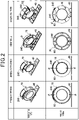
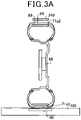
- Fig. 2 shows variations in a position in the tire 60 in which the relay circuit 70 is arranged.
- a tread portion type is a type in which the relay circuit 70 is provided on an outer circumference of the tire 60.
- the tread portion type allows a shortest distance between the power transmission coil 40 and the relay circuit 70.
- a distance between the relay circuit 70 and the power reception coil 240 can be shortened. Can be.
- the tread portion type includes the relay coils 71a1 and 71a2.
- the tire 60 ordinarily includes a steel belt 64 to enhance rigidity.
- the relay coils 71a1 and 71a2 are arranged on an inner side of the steel belt 64 of the tire 60.
- the steel belt 64 is formed from a non-conductive material. If the steel belt 64 is formed from a non-conductive material, eddy currents can be suppressed from being generated in the steel belt 64 due to variations in the magnetic fluxes ⁇ that pass through the relay coils 71a1 and 71a2.
- the relay coils 71a1 and 71a2 may be formed as a portion of the steel belt 64 and used as a member that provides functions of the steel belt 64. Because the relay coils 71a1 and 71a2 and the steel belt 64 can be used in combination, the tire 60 can be reduced in weight and unsprung weight can be reduced.
- the relay circuit 70 is arranged along a circumference of a wheel rather than the tire 60 itself. It can be said that the relay circuit 70 is arranged on an outer circumference of the tire 60 in the tread portion type, and the relay circuit 70 is arranged on an inner circumference of the tire 60 in the wheel-attached type.
- the wheel-attached type is advantageous in that, even when the tire 60 that is a consumable item is replaced, the relay circuit 70 can be used as is if the wheel is not replaced.
- the wheel-attached type includes relay coils 72a1 and 72a2.
- the relay coils 72a1 and 72a2 are arranged along an outer circumference of a wheel 66.
- the power reception coil 240 is arranged vertically above the tire 60.
- the relay circuit 70 is provided in a side wall of the tire 60.
- a gap between the relay circuit 70 and the power transmission coil 40 is midway between the gaps in a tread portion arrangement and wheel attachment.
- a plurality of power transmission coils 40 are arrayed along the road 105.
- An orientation of the magnetic flux of the power transmission coils 40 is the same in a direction along the road 105, but opposite that of the power transmission coils 40 that are adjacent in a direction intersecting the road 105.
- the magnetic flux that is emitted from the power transmission coil 40 of a certain row passes through the relay circuit 70 and enters the power transmission circuit 40 of an adjacent row. Therefore, the magnetic flux is easily closed.
- the magnetic flux that passes through the relay circuit does not pass through the wheel 66, eddy currents are not generated in the wheel 66, and loss due to eddy currents can be reduced.
- the side wall type includes relay coils 73a1 and 73a2.
- the relay coils 73a1 and 73a2 are arranged on a surface of the tire 60 on an inner side of the vehicle 202.
- the side wall type may be configured to include relay coils 74a1 and 74a2 shown in Fig. 3D instead of the relay coils 73a1 and 73a2 or in addition to the relay coils 73a1 and 73a2.
- the relay coils 74a1 and 74a2 are arranged on a surface of the tire 60 on an outer side of the vehicle 202.
- a power reception coil 241 is arranged on a surface of a tire house 67 that faces the tire 60.
- a plane that is formed by the relay circuit 70 is in a radial direction of a front wheel tire.
- the orientation of the magnetic flux of adjacent power transmission coils 40 alternates along the road 105.
- the power reception coil 240 is also preferably divided into two. The magnetic flux that passes through the relay circuit 70 passes through the two divided power reception coils 240. In addition, the magnetic flux can be easily closed.
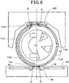
- the tire 60 includes six relay coils 71a1, 71a2, 71b1, 71b2, 71c1, and 71c2.
- a single relay circuit 70 is configured by the relay coils 71a1 and 71a2.
- the relay coils 71b1 and 71b2 and the relay coils 71c1 and 71c2 also respectively configure the relay circuits 70.
- the relay coil is referred to as a relay coil 71.
- the relay coils 71a1 and 71a2 are in point symmetrical positions relative to a rotation center O of the tire 60.
- the relay coils 71b1 and 71b2 and the relay coils 71c1 and 71c2 are also similarly in point symmetrical positions relative to the rotational center O of the tire 60.
- the other relay coil 71a2 opposes the power reception coil 240. This similarly applies to the relay coils 71b1 and
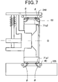
- the relay coils 71a1 and 71a2 are connected in series.
- the relay coil 71a1 opposes the power transmission coil 40
- the relay coil 71a2 opposes the power reception coil 240.
- the magnetic flux ⁇ that is generated in the power transmission coil 40 penetrates the relay coil 71a1.
- the relay coil 71a1 generates an induced current and electric power is transferred from the power transmission coil 40 to the relay coil 71a1.
- the current also flows to the relay coil 71a2 that is connected in series to the relay coil 71a1, and the magnetic flux ⁇ is generated.
- the magnetic flux ⁇ that is generated in the relay coil 71a2 passes through the power reception coil 240, and electric power is transferred from the relay coil 71a2 to the power reception coil 240. That is, when the tire 60 rotates 180° and the relay coil 71a2 opposes the power transmission coil 40, the relay coil 71a1 that is in a symmetrical position opposes the power reception coil 240. This similarly applies to the relay coils 71b1 and 71b2 and the relay coils 71c1 and 71c2 as well.
- Fig. 8 shows the relay circuit 70 shown in Fig. 2 in further detail.
- the relay coils 71a1 and 71a2 may configure a single relay circuit 70 by being connected in series with two resonance capacitors C2 therebetween.
- illustration of the capacitors is omitted.
- the relay coils 71b1 and 71b2 and the relay coils 71c1 and 71c2 similarly respectively configure the relay circuits 70 by being connected in series with two resonance capacitors C2 therebetween. That is, a single tire 60 includes three relay circuits 70.
- a number of relay circuits 70 that are provided in the tire 60 is not limited to three and is merely required to be one or more.
- a resonance capacitor C1 is connected in series to the power transmission coil 40, and a resonance capacitor C3 is connected in series to the power reception coil 240.
- the resonance capacitor may be connected in parallel to the coil.
- a filter or the like may be provided in an earlier stage from the power transmission coil and a later stage from the power reception coil.
- ⁇ 1 is an angular frequency
- Ma is mutual inductance between the power transmission coil 40 and the relay coil 71a
- ka is a coupling coefficient of the power transmission coil 40 and the relay coil 71a1.
- the mutual inductance Ma and the coupling coefficient ka are values that vary based on a rotation angle of the tire 60.
- the [ ⁇ ] sign before the mutual inductance Ma is [+] when winding directions of the two coils around the penetrating magnetic flux ⁇ are the same, and [-] when the winding directions are opposite.
- Lc L 2 + L 3 ⁇ 2
- Mc L 2 + L3 ⁇ 2 kc L 2 ⁇ L 3 1 / 2 .
- inductance of the relay coils 71a1 and 71a2 is L2
- electrical resistance of the relay coils 71a1 and 71a2 and wiring is R2
- inductance of the power reception coil 240 is L3
- the frequencies f1, f2, and f3 need not completely match and may be frequencies that are within a fixed range that is centered on a resonance frequency at which the inductance Lb of the relay circuit 70 that includes the relay coils 71a1 and 71a2 described hereafter is a local maximum.
- a difference between the inductance when the power transmission coil 40 and the relay coil 71a1 oppose each other and the inductance when the relay coil 71a2 and the power reception coil 240 oppose each other may be equal to or less than an amount that is prescribed in advance.
- Fig. 9 shows the inductance Lb of the relay circuit 70 that includes the relay coils 71a1 and 71a2.
- the inductance Lb is a local maximum when the relay coils 71a1 and 71a2 are in the positions that oppose the power transmission coil 40 and the power reception coil 240. This is because, as shown in Fig. 6 and Fig. 7 , the magnetic flux ⁇ that passes through the power transmission coil 40 and the relay coil 71a1 is a local maximum and the magnetic flux ⁇ that passes through the relay coil 71a2 and the power reception coil 240 is a local maximum when the relay coil 71a1 is in the position that opposes the power transmission coil 40.
- the inductance Lb decreases. Subsequently, when the tire 60 rotates to a position in which the relay coil 71a1 opposes the power reception coil 240 and the relay coil 71a2 opposes the power transmission coil 40, the inductance Lb becomes a local maximum. This is because the magnetic flux ⁇ that passes through the power transmission coil 40 and the relay coil 71a2 becomes a local maximum, and the magnetic flux ⁇ that passes through the relay coil 71a1 and the power reception circuit 240 becomes a local maximum.
- a capacitance of the resonance capacitor C2 is set to a local maximum Lmax of the inductance Lb or a capacitance that is within a range from the local maximum Lmax of the inductance Lb to a design value W.
- the design value W is determined in a following manner.
- the design value W is 2Lmax / N.
- the capacitance of the resonance capacitor C2 is a capacitance in which the inductance Lb falls within a range from Lmax to Lmax (1 - 2 / N).
- the value of N is 6. Therefore, the capacitance of the resonance capacitor C2 is a capacitance in which the inductance Lb falls within a range from Lmax to 2Lmax / 3.
- the capacitance of the resonance capacitor C2 is a capacitance in which the resonance frequency of the power transmission coil 40, the power reception coil 240, and the relay coils 71a1 to 71c2 is a frequency within a fixed range that is centered on a frequency that is prescribed in advance, loss can be reduced and power transfer efficiency can be improved.
- a size in a circumferential direction of the relay coils 71a1, 71b1, and 71c1 may be slightly smaller than half a circumference, and portions thereof may overlap.
- illustration of the relay coils 71a2, 71b2, and 71c2 is omitted.
- the size in the circumferential direction is slightly smaller than half the circumference, portions thereof overlap, and the relay coils 71a2, 71b2, and 71c2 are provided in positions that are point-symmetrical to the relay coils 71a1, 71b1, and 71c1 relative to the rotational center O of the tire 60.
- the relay coils 71a1 and 71a2 are electrically connected by being connected by wiring.
- the relay coils 71a1 and 71a2 may not be connected by wiring and may not be electrically connected.
- the relay coil 71a1 opposes the power transmission coil 40
- electrical energy is accumulated in the relay coil 71a1 and the resonance coil C2.
- the tire 60 rotates and the relay coil 71a1 opposes the power reception coil 240
- the electrical energy that is accumulated in the relay coil 71a1 and the resonance coil C2 is transferred to the power reception coil 240.
- the relay coils 71a1 and 71a2 being connected by wiring is preferable because electrical energy can be transferred from the relay coil 71a2 to the power reception coil 240 simultaneously with the relay coil 71a1 receiving the transfer of electrical energy from the power transmission coil 40.
- each relay circuit 70 includes two relay coils, such as the relay coils 71a1 and 71a2.
- the relay circuit 70 may be configured to include a single relay coil 71d.
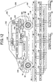
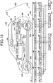
- the relay circuit 20 may be provided in a wheel cap 68 of the tire 60. Electric power can be similarly transferred from the power transmission coil 40 to the power reception coil 240 through the relay circuit 70.
- the vehicle 202 may include a fender cover 208 that covers a tire from an outer side and be configured such that the power reception coil 240 is provided on the tire 60 side of the fender cover 208.
- the power reception coil 240 may be provided in only the fender cover of the tire 60 that is not a steering wheel. This is because power transfer is not easily affected by steering of the tire 60.
- a shape pattern that indicates a shape of the relay coil 71 is identical to a shape pattern of a tread portion 69 of the tire 60.
- the relay coil 71 is arranged such as to match the shape pattern of the tread portion 69.
- Fig. 15 shows a cross-section of the tire in Fig. 14 .
- the relay coil 71 is provided in the tread portion 69 further toward the outer circumferential side than the steel belt 64 is.
- the steel belt 64 may be covered by a conductive shield.
- a yoke may be provided between the relay coil 71 and the steel belt 71. The magnetic flux is blocked by the yoke and does not penetrate the steel belt 64.
- the power reception coil 240 is provided in correspondence to front and rear tires 60, only the power reception coil 240 that corresponds to the tire 60 of a front wheel or only the power reception coil 240 that corresponds to the tire 60 of a rear wheel may be provided.
- the number of relay coils 71 is described as being six. However, the number may be a plurality that is two or more. In addition, according to the above-described embodiments, two relay coils 71 that are in point symmetrical positions are connected in series. However, for example, the number of relay coils 71 may be 3n, and three relay coils 71 that are in three rotationally symmetrical positions may be connected in series.
- control apparatus and the method thereof described in the present disclosure may be actualized by a dedicated computer that is provided such as to be configured by a processor and a memory, the processor being programmed to provide one or a plurality of functions that are realized by a computer program.
- the control apparatus and the method thereof described in the present disclosure may be actualized by a dedicated computer that is provided by a processor being configured by a single dedicated hardware logic circuit or more.
- the control apparatus and the method thereof described in the present disclosure may be actualized by a single dedicated computer or more, the dedicated computer being configured by a combination of a processor that is programmed to provide one or a plurality of functions, a memory, and a processor that is configured by a single hardware logic circuit or more.
- the computer program may be stored in a non-transitory computer-readable storage medium that can be read by a computer as instructions performed by the computer.
Landscapes
- Engineering & Computer Science (AREA)
- Power Engineering (AREA)
- Mechanical Engineering (AREA)
- Computer Networks & Wireless Communication (AREA)
- Transportation (AREA)
- Life Sciences & Earth Sciences (AREA)
- Sustainable Development (AREA)
- Sustainable Energy (AREA)
- Current-Collector Devices For Electrically Propelled Vehicles (AREA)
- Electric Propulsion And Braking For Vehicles (AREA)
- Tires In General (AREA)
- Charge And Discharge Circuits For Batteries Or The Like (AREA)
Applications Claiming Priority (2)
| Application Number | Priority Date | Filing Date | Title |
|---|---|---|---|
| JP2019137399A JP7057326B2 (ja) | 2019-07-26 | 2019-07-26 | 走行中給電システム |
| PCT/JP2020/026557 WO2021020046A1 (fr) | 2019-07-26 | 2020-07-07 | Système d'alimentation en énergie pendant un déplacement |
Publications (3)
| Publication Number | Publication Date |
|---|---|
| EP4005832A1 true EP4005832A1 (fr) | 2022-06-01 |
| EP4005832A4 EP4005832A4 (fr) | 2022-10-05 |
| EP4005832B1 EP4005832B1 (fr) | 2023-11-01 |
Family
ID=74229919
Family Applications (1)
| Application Number | Title | Priority Date | Filing Date |
|---|---|---|---|
| EP20848123.4A Active EP4005832B1 (fr) | 2019-07-26 | 2020-07-07 | Système d'alimentation en énergie pendant un déplacement |
Country Status (5)
| Country | Link |
|---|---|
| US (1) | US11984735B2 (fr) |
| EP (1) | EP4005832B1 (fr) |
| JP (1) | JP7057326B2 (fr) |
| CN (1) | CN114269592B (fr) |
| WO (1) | WO2021020046A1 (fr) |
Families Citing this family (12)
| Publication number | Priority date | Publication date | Assignee | Title |
|---|---|---|---|---|
| JP7388629B2 (ja) * | 2019-07-25 | 2023-11-29 | 国立大学法人 東京大学 | 無線受電システム、移動体、及び車輪 |
| JP7057326B2 (ja) | 2019-07-26 | 2022-04-19 | 株式会社デンソー | 走行中給電システム |
| JP7172900B2 (ja) | 2019-07-26 | 2022-11-16 | 株式会社デンソー | 走行中給電システム |
| JP2021098384A (ja) * | 2019-12-19 | 2021-07-01 | 株式会社ブリヂストン | タイヤ・ホイール組立体 |
| US11845347B2 (en) | 2021-05-12 | 2023-12-19 | David Alan Copeland | Precision charging control of an untethered vehicle with a modular vehicle charging roadway |
| WO2022254954A1 (fr) * | 2021-05-31 | 2022-12-08 | 株式会社デンソー | Système d'alimentation électrique |
| CN117413446A (zh) * | 2021-05-31 | 2024-01-16 | 株式会社电装 | 供电系统 |
| WO2023069908A1 (fr) * | 2021-10-18 | 2023-04-27 | Hevo Inc. | Systèmes et procédés de recharge dynamique le long d'une route |
| JP7731107B2 (ja) * | 2022-05-18 | 2025-08-29 | 株式会社デンソー | 給電装置および給電システム |
| JP2024007234A (ja) * | 2022-07-05 | 2024-01-18 | 株式会社デンソー | 監視システム、監視装置、自律走行車両、監視方法、監視プログラム |
| DE112023002191T5 (de) * | 2022-07-07 | 2025-04-17 | The Yokohama Rubber Co., Ltd. | Reifen und stromzufuhrsystem |
| JP2024118520A (ja) * | 2023-02-21 | 2024-09-02 | 株式会社デンソー | 受電装置 |
Family Cites Families (33)
| Publication number | Priority date | Publication date | Assignee | Title |
|---|---|---|---|---|
| USRE19633E (en) | 1935-07-09 | Railway traffic controlling | ||
| US7352290B2 (en) | 2002-09-09 | 2008-04-01 | Eskridge Gregory S | Aware patrol vehicle |
| US20080084285A1 (en) | 2006-10-05 | 2008-04-10 | Kulvir Singh Bhogal | System and method for autonomic detection of tire tread wear |
| JP4453741B2 (ja) | 2007-10-25 | 2010-04-21 | トヨタ自動車株式会社 | 電動車両および車両用給電装置 |
| JP2009184521A (ja) | 2008-02-06 | 2009-08-20 | Bridgestone Corp | 空気入りタイヤ |
| US9601261B2 (en) | 2008-09-27 | 2017-03-21 | Witricity Corporation | Wireless energy transfer using repeater resonators |
| US20110031047A1 (en) | 2009-08-04 | 2011-02-10 | Tarr Energy Group, Llc | In-motion inductive charging system having a wheel-mounted secondary coil |
| JP5487944B2 (ja) | 2009-12-18 | 2014-05-14 | 日産自動車株式会社 | 非接触給電装置 |
| EP2543535A4 (fr) | 2010-03-04 | 2014-05-14 | Honda Motor Co Ltd | Véhicule électrique |
| US8725330B2 (en) | 2010-06-02 | 2014-05-13 | Bryan Marc Failing | Increasing vehicle security |
| WO2012074670A1 (fr) | 2010-11-04 | 2012-06-07 | Blackbird Technology Holdings, Inc. | Procédé et appareil pour la surveillance de la pression des pneus |
| JP2012157231A (ja) | 2011-01-25 | 2012-08-16 | Yoshiaki Kashiwade | 電気自動車の電源供給 |
| EP2996123B1 (fr) | 2011-06-27 | 2017-06-14 | Toyota Jidosha Kabushiki Kaisha | Dispositif de réception de puissance, dispositif de transmission de puissance et système de transfert de puissance |
| JP5691939B2 (ja) | 2011-08-30 | 2015-04-01 | 三菱自動車工業株式会社 | ワイヤレス給電システム |
| KR101217655B1 (ko) | 2011-11-04 | 2013-01-02 | 포항공과대학교 산학협력단 | 차량용 무선 전력 전송 시스템 |
| JP6263934B2 (ja) * | 2013-10-03 | 2018-01-24 | 日産自動車株式会社 | 非接触給電装置 |
| MY161712A (en) * | 2014-01-31 | 2017-05-15 | Nissan Motor | Wireless power supply system and power transmission device |
| US20160023557A1 (en) | 2014-07-25 | 2016-01-28 | Qualcomm Incorporated | Devices, systems, and method for dynamic electric vehicle charging with position detection |
| WO2016132560A1 (fr) | 2015-02-20 | 2016-08-25 | 富士通株式会社 | Récepteur de puissance et système de transmission de puissance |
| JP6541425B2 (ja) | 2015-05-18 | 2019-07-10 | 株式会社テクノバ | 非接触給電システム |
| JP2016226072A (ja) | 2015-05-27 | 2016-12-28 | Tdk株式会社 | ワイヤレス給電装置およびワイヤレス電力伝送システム |
| JP2017093113A (ja) * | 2015-11-09 | 2017-05-25 | 船井電機株式会社 | 電動車 |
| KR102048652B1 (ko) * | 2016-05-23 | 2019-11-25 | 닛산 지도우샤 가부시키가이샤 | 비접촉 급전 시스템의 코일 위치 검출 방법 및 비접촉 급전 시스템 |
| CN106143185A (zh) | 2016-06-28 | 2016-11-23 | 浙江大学 | 一种基于轮胎的新型电动汽车行驶中无线供电系统 |
| CN106451822A (zh) * | 2016-12-13 | 2017-02-22 | 北京理工大学 | 一种用于无线电能传输的智能充电装置 |
| US20200130437A1 (en) | 2018-10-25 | 2020-04-30 | Applied Mechatronic Products, Llc | Apparatus and method for automatic tire inflation system |
| US20220063415A1 (en) | 2018-12-17 | 2022-03-03 | Bridgestone Corporation | Tire, vehicle power feeding apparatus and automobile |
| JP6781797B2 (ja) | 2019-05-07 | 2020-11-04 | 三菱重工サーマルシステムズ株式会社 | 冷凍機制御システム、サーバ端末装置、冷凍機ユニットの制御方法およびプログラム |
| US11641053B2 (en) | 2019-07-19 | 2023-05-02 | The Goodyear Tire & Rubber Company | Reader system for tire with an integrated RFID and TPMS sensor |
| JP2021020514A (ja) | 2019-07-25 | 2021-02-18 | 株式会社ブリヂストン | タイヤ・ホイール組立体及びタイヤ |
| JP7057326B2 (ja) | 2019-07-26 | 2022-04-19 | 株式会社デンソー | 走行中給電システム |
| JP7172900B2 (ja) | 2019-07-26 | 2022-11-16 | 株式会社デンソー | 走行中給電システム |
| CN110549799B (zh) | 2019-09-11 | 2022-02-08 | 肇庆中晶实业有限公司 | 一种胎压监测控制方法和系统 |
-
2019
- 2019-07-26 JP JP2019137399A patent/JP7057326B2/ja active Active
-
2020
- 2020-07-07 EP EP20848123.4A patent/EP4005832B1/fr active Active
- 2020-07-07 WO PCT/JP2020/026557 patent/WO2021020046A1/fr not_active Ceased
- 2020-07-07 CN CN202080053777.8A patent/CN114269592B/zh active Active
-
2022
- 2022-01-26 US US17/585,195 patent/US11984735B2/en active Active
Also Published As
| Publication number | Publication date |
|---|---|
| JP7057326B2 (ja) | 2022-04-19 |
| JP2021023002A (ja) | 2021-02-18 |
| CN114269592A (zh) | 2022-04-01 |
| CN114269592B (zh) | 2024-06-14 |
| US20220149666A1 (en) | 2022-05-12 |
| EP4005832A4 (fr) | 2022-10-05 |
| WO2021020046A1 (fr) | 2021-02-04 |
| US11984735B2 (en) | 2024-05-14 |
| EP4005832B1 (fr) | 2023-11-01 |
Similar Documents
| Publication | Publication Date | Title |
|---|---|---|
| EP4005832B1 (fr) | Système d'alimentation en énergie pendant un déplacement | |
| EP4005851B1 (fr) | Système d'alimentation électrique pendant le déplacement | |
| EP2407338B1 (fr) | Véhicule électrique | |
| US10202045B2 (en) | Vehicle with shielded power receiving coil | |
| CN112400267B (zh) | 非接触供电装置及非接触供电系统 | |
| KR101717393B1 (ko) | 비접촉 급전 장치 | |
| US20150266385A1 (en) | Energy transmission device and energy transmission arrangement | |
| JP6146121B2 (ja) | 非接触給電システム | |
| JP6135425B2 (ja) | 非接触受電装置の車載構造 | |
| JP6110758B2 (ja) | 車両誘導装置 | |
| KR20150125991A (ko) | 비접촉 급전 장치 | |
| US12151570B2 (en) | Contactless power supply system and coil unit thereof | |
| EP3282556B1 (fr) | Système d'alimentation électrique sans contact | |
| JP5276421B2 (ja) | 自動車 | |
| US11850952B2 (en) | System for power feeding during traveling | |
| JP6232699B2 (ja) | 非接触給電システム | |
| US12292485B2 (en) | Magnetic detection system | |
| JP7715659B2 (ja) | 異常診断システム及び異常判定方法 | |
| JP2011244641A (ja) | 車両用非接触受電装置 | |
| JP2024081965A (ja) | 受電装置及び非接触給電システム | |
| JP5962613B2 (ja) | 非接触受電装置 |
Legal Events
| Date | Code | Title | Description |
|---|---|---|---|
| STAA | Information on the status of an ep patent application or granted ep patent |
Free format text: STATUS: THE INTERNATIONAL PUBLICATION HAS BEEN MADE |
|
| PUAI | Public reference made under article 153(3) epc to a published international application that has entered the european phase |
Free format text: ORIGINAL CODE: 0009012 |
|
| STAA | Information on the status of an ep patent application or granted ep patent |
Free format text: STATUS: REQUEST FOR EXAMINATION WAS MADE |
|
| 17P | Request for examination filed |
Effective date: 20220207 |
|
| AK | Designated contracting states |
Kind code of ref document: A1 Designated state(s): AL AT BE BG CH CY CZ DE DK EE ES FI FR GB GR HR HU IE IS IT LI LT LU LV MC MK MT NL NO PL PT RO RS SE SI SK SM TR |
|
| STAA | Information on the status of an ep patent application or granted ep patent |
Free format text: STATUS: EXAMINATION IS IN PROGRESS |
|
| A4 | Supplementary search report drawn up and despatched |
Effective date: 20220905 |
|
| RIC1 | Information provided on ipc code assigned before grant |
Ipc: B60M 7/00 20060101ALI20220830BHEP Ipc: B60L 53/38 20190101ALI20220830BHEP Ipc: B60L 50/53 20190101ALI20220830BHEP Ipc: H02J 7/00 20060101ALI20220830BHEP Ipc: H02J 50/50 20160101ALI20220830BHEP Ipc: H02J 50/12 20160101ALI20220830BHEP Ipc: B60L 5/00 20060101ALI20220830BHEP Ipc: B60C 19/00 20060101AFI20220830BHEP |
|
| 17Q | First examination report despatched |
Effective date: 20220919 |
|
| DAV | Request for validation of the european patent (deleted) | ||
| DAX | Request for extension of the european patent (deleted) | ||
| GRAP | Despatch of communication of intention to grant a patent |
Free format text: ORIGINAL CODE: EPIDOSNIGR1 |
|
| STAA | Information on the status of an ep patent application or granted ep patent |
Free format text: STATUS: GRANT OF PATENT IS INTENDED |
|
| INTG | Intention to grant announced |
Effective date: 20230601 |
|
| GRAS | Grant fee paid |
Free format text: ORIGINAL CODE: EPIDOSNIGR3 |
|
| GRAA | (expected) grant |
Free format text: ORIGINAL CODE: 0009210 |
|
| STAA | Information on the status of an ep patent application or granted ep patent |
Free format text: STATUS: THE PATENT HAS BEEN GRANTED |
|
| AK | Designated contracting states |
Kind code of ref document: B1 Designated state(s): AL AT BE BG CH CY CZ DE DK EE ES FI FR GB GR HR HU IE IS IT LI LT LU LV MC MK MT NL NO PL PT RO RS SE SI SK SM TR |
|
| REG | Reference to a national code |
Ref country code: GB Ref legal event code: FG4D |
|
| REG | Reference to a national code |
Ref country code: CH Ref legal event code: EP |
|
| REG | Reference to a national code |
Ref country code: IE Ref legal event code: FG4D |
|
| REG | Reference to a national code |
Ref country code: DE Ref legal event code: R096 Ref document number: 602020020467 Country of ref document: DE |
|
| REG | Reference to a national code |
Ref country code: LT Ref legal event code: MG9D |
|
| REG | Reference to a national code |
Ref country code: NL Ref legal event code: MP Effective date: 20231101 |
|
| PG25 | Lapsed in a contracting state [announced via postgrant information from national office to epo] |
Ref country code: GR Free format text: LAPSE BECAUSE OF FAILURE TO SUBMIT A TRANSLATION OF THE DESCRIPTION OR TO PAY THE FEE WITHIN THE PRESCRIBED TIME-LIMIT Effective date: 20240202 |
|
| PG25 | Lapsed in a contracting state [announced via postgrant information from national office to epo] |
Ref country code: IS Free format text: LAPSE BECAUSE OF FAILURE TO SUBMIT A TRANSLATION OF THE DESCRIPTION OR TO PAY THE FEE WITHIN THE PRESCRIBED TIME-LIMIT Effective date: 20240301 |
|
| PG25 | Lapsed in a contracting state [announced via postgrant information from national office to epo] |
Ref country code: LT Free format text: LAPSE BECAUSE OF FAILURE TO SUBMIT A TRANSLATION OF THE DESCRIPTION OR TO PAY THE FEE WITHIN THE PRESCRIBED TIME-LIMIT Effective date: 20231101 |
|
| REG | Reference to a national code |
Ref country code: AT Ref legal event code: MK05 Ref document number: 1626811 Country of ref document: AT Kind code of ref document: T Effective date: 20231101 |
|
| PG25 | Lapsed in a contracting state [announced via postgrant information from national office to epo] |
Ref country code: NL Free format text: LAPSE BECAUSE OF FAILURE TO SUBMIT A TRANSLATION OF THE DESCRIPTION OR TO PAY THE FEE WITHIN THE PRESCRIBED TIME-LIMIT Effective date: 20231101 |
|
| PG25 | Lapsed in a contracting state [announced via postgrant information from national office to epo] |
Ref country code: AT Free format text: LAPSE BECAUSE OF FAILURE TO SUBMIT A TRANSLATION OF THE DESCRIPTION OR TO PAY THE FEE WITHIN THE PRESCRIBED TIME-LIMIT Effective date: 20231101 |
|
| PG25 | Lapsed in a contracting state [announced via postgrant information from national office to epo] |
Ref country code: ES Free format text: LAPSE BECAUSE OF FAILURE TO SUBMIT A TRANSLATION OF THE DESCRIPTION OR TO PAY THE FEE WITHIN THE PRESCRIBED TIME-LIMIT Effective date: 20231101 |
|
| PG25 | Lapsed in a contracting state [announced via postgrant information from national office to epo] |
Ref country code: NL Free format text: LAPSE BECAUSE OF FAILURE TO SUBMIT A TRANSLATION OF THE DESCRIPTION OR TO PAY THE FEE WITHIN THE PRESCRIBED TIME-LIMIT Effective date: 20231101 Ref country code: LT Free format text: LAPSE BECAUSE OF FAILURE TO SUBMIT A TRANSLATION OF THE DESCRIPTION OR TO PAY THE FEE WITHIN THE PRESCRIBED TIME-LIMIT Effective date: 20231101 Ref country code: IS Free format text: LAPSE BECAUSE OF FAILURE TO SUBMIT A TRANSLATION OF THE DESCRIPTION OR TO PAY THE FEE WITHIN THE PRESCRIBED TIME-LIMIT Effective date: 20240301 Ref country code: GR Free format text: LAPSE BECAUSE OF FAILURE TO SUBMIT A TRANSLATION OF THE DESCRIPTION OR TO PAY THE FEE WITHIN THE PRESCRIBED TIME-LIMIT Effective date: 20240202 Ref country code: ES Free format text: LAPSE BECAUSE OF FAILURE TO SUBMIT A TRANSLATION OF THE DESCRIPTION OR TO PAY THE FEE WITHIN THE PRESCRIBED TIME-LIMIT Effective date: 20231101 Ref country code: BG Free format text: LAPSE BECAUSE OF FAILURE TO SUBMIT A TRANSLATION OF THE DESCRIPTION OR TO PAY THE FEE WITHIN THE PRESCRIBED TIME-LIMIT Effective date: 20240201 Ref country code: AT Free format text: LAPSE BECAUSE OF FAILURE TO SUBMIT A TRANSLATION OF THE DESCRIPTION OR TO PAY THE FEE WITHIN THE PRESCRIBED TIME-LIMIT Effective date: 20231101 Ref country code: PT Free format text: LAPSE BECAUSE OF FAILURE TO SUBMIT A TRANSLATION OF THE DESCRIPTION OR TO PAY THE FEE WITHIN THE PRESCRIBED TIME-LIMIT Effective date: 20240301 |
|
| PG25 | Lapsed in a contracting state [announced via postgrant information from national office to epo] |
Ref country code: SE Free format text: LAPSE BECAUSE OF FAILURE TO SUBMIT A TRANSLATION OF THE DESCRIPTION OR TO PAY THE FEE WITHIN THE PRESCRIBED TIME-LIMIT Effective date: 20231101 Ref country code: RS Free format text: LAPSE BECAUSE OF FAILURE TO SUBMIT A TRANSLATION OF THE DESCRIPTION OR TO PAY THE FEE WITHIN THE PRESCRIBED TIME-LIMIT Effective date: 20231101 Ref country code: PL Free format text: LAPSE BECAUSE OF FAILURE TO SUBMIT A TRANSLATION OF THE DESCRIPTION OR TO PAY THE FEE WITHIN THE PRESCRIBED TIME-LIMIT Effective date: 20231101 Ref country code: NO Free format text: LAPSE BECAUSE OF FAILURE TO SUBMIT A TRANSLATION OF THE DESCRIPTION OR TO PAY THE FEE WITHIN THE PRESCRIBED TIME-LIMIT Effective date: 20240201 Ref country code: LV Free format text: LAPSE BECAUSE OF FAILURE TO SUBMIT A TRANSLATION OF THE DESCRIPTION OR TO PAY THE FEE WITHIN THE PRESCRIBED TIME-LIMIT Effective date: 20231101 Ref country code: HR Free format text: LAPSE BECAUSE OF FAILURE TO SUBMIT A TRANSLATION OF THE DESCRIPTION OR TO PAY THE FEE WITHIN THE PRESCRIBED TIME-LIMIT Effective date: 20231101 |
|
| PG25 | Lapsed in a contracting state [announced via postgrant information from national office to epo] |
Ref country code: DK Free format text: LAPSE BECAUSE OF FAILURE TO SUBMIT A TRANSLATION OF THE DESCRIPTION OR TO PAY THE FEE WITHIN THE PRESCRIBED TIME-LIMIT Effective date: 20231101 |
|
| PG25 | Lapsed in a contracting state [announced via postgrant information from national office to epo] |
Ref country code: CZ Free format text: LAPSE BECAUSE OF FAILURE TO SUBMIT A TRANSLATION OF THE DESCRIPTION OR TO PAY THE FEE WITHIN THE PRESCRIBED TIME-LIMIT Effective date: 20231101 |
|
| PG25 | Lapsed in a contracting state [announced via postgrant information from national office to epo] |
Ref country code: SK Free format text: LAPSE BECAUSE OF FAILURE TO SUBMIT A TRANSLATION OF THE DESCRIPTION OR TO PAY THE FEE WITHIN THE PRESCRIBED TIME-LIMIT Effective date: 20231101 |
|
| PG25 | Lapsed in a contracting state [announced via postgrant information from national office to epo] |
Ref country code: SM Free format text: LAPSE BECAUSE OF FAILURE TO SUBMIT A TRANSLATION OF THE DESCRIPTION OR TO PAY THE FEE WITHIN THE PRESCRIBED TIME-LIMIT Effective date: 20231101 Ref country code: SK Free format text: LAPSE BECAUSE OF FAILURE TO SUBMIT A TRANSLATION OF THE DESCRIPTION OR TO PAY THE FEE WITHIN THE PRESCRIBED TIME-LIMIT Effective date: 20231101 Ref country code: IT Free format text: LAPSE BECAUSE OF FAILURE TO SUBMIT A TRANSLATION OF THE DESCRIPTION OR TO PAY THE FEE WITHIN THE PRESCRIBED TIME-LIMIT Effective date: 20231101 Ref country code: EE Free format text: LAPSE BECAUSE OF FAILURE TO SUBMIT A TRANSLATION OF THE DESCRIPTION OR TO PAY THE FEE WITHIN THE PRESCRIBED TIME-LIMIT Effective date: 20231101 Ref country code: DK Free format text: LAPSE BECAUSE OF FAILURE TO SUBMIT A TRANSLATION OF THE DESCRIPTION OR TO PAY THE FEE WITHIN THE PRESCRIBED TIME-LIMIT Effective date: 20231101 Ref country code: CZ Free format text: LAPSE BECAUSE OF FAILURE TO SUBMIT A TRANSLATION OF THE DESCRIPTION OR TO PAY THE FEE WITHIN THE PRESCRIBED TIME-LIMIT Effective date: 20231101 |
|
| REG | Reference to a national code |
Ref country code: DE Ref legal event code: R097 Ref document number: 602020020467 Country of ref document: DE |
|
| PLBE | No opposition filed within time limit |
Free format text: ORIGINAL CODE: 0009261 |
|
| STAA | Information on the status of an ep patent application or granted ep patent |
Free format text: STATUS: NO OPPOSITION FILED WITHIN TIME LIMIT |
|
| 26N | No opposition filed |
Effective date: 20240802 |
|
| PG25 | Lapsed in a contracting state [announced via postgrant information from national office to epo] |
Ref country code: SI Free format text: LAPSE BECAUSE OF FAILURE TO SUBMIT A TRANSLATION OF THE DESCRIPTION OR TO PAY THE FEE WITHIN THE PRESCRIBED TIME-LIMIT Effective date: 20231101 |
|
| PG25 | Lapsed in a contracting state [announced via postgrant information from national office to epo] |
Ref country code: SI Free format text: LAPSE BECAUSE OF FAILURE TO SUBMIT A TRANSLATION OF THE DESCRIPTION OR TO PAY THE FEE WITHIN THE PRESCRIBED TIME-LIMIT Effective date: 20231101 |
|
| PG25 | Lapsed in a contracting state [announced via postgrant information from national office to epo] |
Ref country code: MC Free format text: LAPSE BECAUSE OF FAILURE TO SUBMIT A TRANSLATION OF THE DESCRIPTION OR TO PAY THE FEE WITHIN THE PRESCRIBED TIME-LIMIT Effective date: 20231101 |
|
| REG | Reference to a national code |
Ref country code: CH Ref legal event code: PL |
|
| PG25 | Lapsed in a contracting state [announced via postgrant information from national office to epo] |
Ref country code: LU Free format text: LAPSE BECAUSE OF NON-PAYMENT OF DUE FEES Effective date: 20240707 |
|
| GBPC | Gb: european patent ceased through non-payment of renewal fee |
Effective date: 20240707 |
|
| PG25 | Lapsed in a contracting state [announced via postgrant information from national office to epo] |
Ref country code: LU Free format text: LAPSE BECAUSE OF NON-PAYMENT OF DUE FEES Effective date: 20240707 |
|
| PG25 | Lapsed in a contracting state [announced via postgrant information from national office to epo] |
Ref country code: BE Free format text: LAPSE BECAUSE OF NON-PAYMENT OF DUE FEES Effective date: 20240731 Ref country code: CH Free format text: LAPSE BECAUSE OF NON-PAYMENT OF DUE FEES Effective date: 20240731 |
|
| PG25 | Lapsed in a contracting state [announced via postgrant information from national office to epo] |
Ref country code: GB Free format text: LAPSE BECAUSE OF NON-PAYMENT OF DUE FEES Effective date: 20240707 |
|
| REG | Reference to a national code |
Ref country code: BE Ref legal event code: MM Effective date: 20240731 |
|
| PG25 | Lapsed in a contracting state [announced via postgrant information from national office to epo] |
Ref country code: IE Free format text: LAPSE BECAUSE OF NON-PAYMENT OF DUE FEES Effective date: 20240707 |
|
| PG25 | Lapsed in a contracting state [announced via postgrant information from national office to epo] |
Ref country code: FI Free format text: LAPSE BECAUSE OF FAILURE TO SUBMIT A TRANSLATION OF THE DESCRIPTION OR TO PAY THE FEE WITHIN THE PRESCRIBED TIME-LIMIT Effective date: 20231101 |
|
| PGFP | Annual fee paid to national office [announced via postgrant information from national office to epo] |
Ref country code: DE Payment date: 20250722 Year of fee payment: 6 |
|
| PGFP | Annual fee paid to national office [announced via postgrant information from national office to epo] |
Ref country code: FR Payment date: 20250725 Year of fee payment: 6 |
|
| PG25 | Lapsed in a contracting state [announced via postgrant information from national office to epo] |
Ref country code: RO Free format text: LAPSE BECAUSE OF FAILURE TO SUBMIT A TRANSLATION OF THE DESCRIPTION OR TO PAY THE FEE WITHIN THE PRESCRIBED TIME-LIMIT Effective date: 20231101 |
|
| PG25 | Lapsed in a contracting state [announced via postgrant information from national office to epo] |
Ref country code: CY Free format text: LAPSE BECAUSE OF FAILURE TO SUBMIT A TRANSLATION OF THE DESCRIPTION OR TO PAY THE FEE WITHIN THE PRESCRIBED TIME-LIMIT; INVALID AB INITIO Effective date: 20200707 |
|
| PG25 | Lapsed in a contracting state [announced via postgrant information from national office to epo] |
Ref country code: HU Free format text: LAPSE BECAUSE OF FAILURE TO SUBMIT A TRANSLATION OF THE DESCRIPTION OR TO PAY THE FEE WITHIN THE PRESCRIBED TIME-LIMIT; INVALID AB INITIO Effective date: 20200707 |