EP4005839A1 - Bâche à précontrainte pouvant être ajustée et bandes de maintien en tant que protection contre les coupures et les surcharges mécaniques - Google Patents
Bâche à précontrainte pouvant être ajustée et bandes de maintien en tant que protection contre les coupures et les surcharges mécaniques Download PDFInfo
- Publication number
- EP4005839A1 EP4005839A1 EP21000251.5A EP21000251A EP4005839A1 EP 4005839 A1 EP4005839 A1 EP 4005839A1 EP 21000251 A EP21000251 A EP 21000251A EP 4005839 A1 EP4005839 A1 EP 4005839A1
- Authority
- EP
- European Patent Office
- Prior art keywords
- tarpaulin
- retaining strip
- retaining
- strips
- strip
- Prior art date
- Legal status (The legal status is an assumption and is not a legal conclusion. Google has not performed a legal analysis and makes no representation as to the accuracy of the status listed.)
- Granted
Links
Images

Classifications
-
- B—PERFORMING OPERATIONS; TRANSPORTING
- B60—VEHICLES IN GENERAL
- B60P—VEHICLES ADAPTED FOR LOAD TRANSPORTATION OR TO TRANSPORT, TO CARRY, OR TO COMPRISE SPECIAL LOADS OR OBJECTS
- B60P7/00—Securing or covering of load on vehicles
- B60P7/06—Securing of load
- B60P7/08—Securing to the vehicle floor or sides
- B60P7/0876—Securing to the vehicle floor or sides using restraining net or tarpaulin in contact with the load
-
- B—PERFORMING OPERATIONS; TRANSPORTING
- B60—VEHICLES IN GENERAL
- B60J—WINDOWS, WINDSCREENS, NON-FIXED ROOFS, DOORS, OR SIMILAR DEVICES FOR VEHICLES; REMOVABLE EXTERNAL PROTECTIVE COVERINGS SPECIALLY ADAPTED FOR VEHICLES
- B60J5/00—Doors
- B60J5/04—Doors arranged at the vehicle sides
- B60J5/06—Doors arranged at the vehicle sides slidable; foldable
- B60J5/062—Doors arranged at the vehicle sides slidable; foldable for utility vehicles or public transport
- B60J5/065—Doors arranged at the vehicle sides slidable; foldable for utility vehicles or public transport with non-rigid elements, e.g. side curtains
Definitions
- the invention relates to an elastic tarpaulin for closing an open space in the structure of a vehicle or building, the tarpaulin being slit manually with a knife and several flexible, elongated and cut-resistant retaining strips being attached to the tarpaulin, each retaining strip being connected at its ends to the body is connected and a lower end is detachably connected to the body via a clamping lever and when the tarpaulin is open the length of at least one retaining strip between two adjacent connection points to the tarpaulin is greater than the distance between the two complementary fastening areas in the adjoining partial area of the tension-free and smoothly laid out on one level and in the closed state of the open area at least one retaining strip is tensioned by being connected to the structure at both ends and the adjacent partial area of the tarpaulin between adjacent connection points so far apart is pulled and prestressed in that it lies flat on the retaining strip.
- the structure of many trucks or railway wagons, containers, warehouses or other structures is a frame made of metal profiles, the large open areas of which are covered and closed with tarpaulins on the long sides. This protects them from the weather and unwanted views.
- the DE 101 50 102 A1 a grid-like, very coarse-meshed network of steel cables that extends across the tarpaulin, which are held in place by glued or welded strips, also made of the plastic fabric of the tarpaulin.
- These steel cables limit the maximum possible cutting length of a cutting knife to the grid size of the steel net. If the elastic tarpaulin and thus also the elastic fabric strips attached to it lengthen under load, the hardly elastic steel cables retain their length and slide on the textile surfaces. Therefore, the disadvantage of the steel cords is that they can only offer very little resistance to forces that impinge from the side. The glued strips themselves can only make a very small contribution to absorbing an additional loading force.
- the EP 1 777 336 A2 explains a double-layered tarpaulin in which the two layers are not connected to one another along spaced strips crossing in a grid-like manner across the tarpaulin, but instead form tube-like tunnels into which steel cables are inserted to prevent cuts. If the elastic tarpaulin and thus the tube-like tunnel lengthen under load, the less elastic steel cables slide on it. Despite this sliding, the steel cables can stop cutting knife blades. However, they can hardly compensate for forces acting from the side, since the support of the ropes in relation to the tarpaulin is severely restricted by the sliding.
- a tarp according to DE 10 2017 001 675 A1 distributes mechanical stresses firstly on a number of very inelastic and cut-resistant vertical strips, for example made of metal, which are arranged at a distance from one another, and secondly on the elastic fabric of the tarpaulin itself, which allows the tarpaulin to close when the free surface of the body is closed is biased.
- a number of very inelastic and cut-resistant vertical strips for example made of metal, which are arranged at a distance from one another, and secondly on the elastic fabric of the tarpaulin itself, which allows the tarpaulin to close when the free surface of the body is closed is biased.
- One limitation is that if the elasticity of the tarpaulin changes, for example due to aging and/or an otherwise reversible industrial accident, there is no provision for appropriate adjustment.
- the invention has set itself the task of reducing these disadvantageous effects and creating a tarpaulin made of elastic fabric, which is reinforced with cut-resistant strips, for example made of steel Strips not only protect against vandalism, slitting with a knife, but also help to achieve the prescribed strength of the tarpaulin against lateral forces and to enable this strength to be maintained over a longer period of time and/or under stressful operating conditions.
- the protection against slashing and the readiness of the tarpaulin to bear lateral loads should also be retained across the entire area when the tarpaulin has temporarily expanded and lengthened under the influence of lateral forces and then contracts again.
- the effort should be as little as possible.
- the willingness of the tarpaulin to bear lateral loads should still be effective over a longer period of time after repeated winding and unwinding or folding and unfolding of the tarpaulin and not require difficult to understand and complex steps in care and maintenance.
- the tarpaulin should be as light, inexpensive and flexible as possible.
- the number of work steps in production should be as low as possible.
- the invention teaches that the distance between the connection points of at least one retaining strip and/or between the fastening areas of the tarpaulin can be changed by means of an adjustment element in order to retension the tarpaulin.
- the invention is based on the principle of significantly improving the transmission and dissipation of a force acting laterally on the tarpaulin to the retaining strips by having a tarpaulin made of elastic fabric not only close the free space in the body, but also to such an extent at the same time as closing it is pretensioned so that the retaining strips, which are hardly elastic compared to the tarpaulin, are influenced by the forces to be absorbed in significantly relieved. This allows the retaining strips to be dimensioned more easily, which reduces the overall cost and weight of the tarpaulin. If the holding strips remain the same, the retaining effect of the tarpaulin against loosened loads is increased.
- This effect is illustrated, for example, by a trampoline in which a fabric similar to that of a truck tarpaulin, which is also elastic, is used. Only through the appropriate all-round pretensioning with tension springs is it tightened to such an extent that it only deforms by a relatively small distance when a jumping person hits it. Thanks to the pretension, the movement of each individual fiber is passed on to the neighboring and crossing other fibers in a shorter time and with a greater amount. As a result, the pressure from the directly touched area is distributed over a large area, so that a jumper can jump surprisingly high on the pre-stressed trampoline.
- PVC is subject to photooxidation when exposed to light through photolysis. This creates various radicals that attack the material by breaking the main chains of the polymer, resulting in the formation and incorporation of various polar compounds, such as peroxides, into the material. As a result of this conversion, the bonds between individual molecules are broken in many places and the finest micro-cracks, including small cracks, form which can be seen on the outer surface of the filaments. Neighboring filaments that are not yet affected take over part of the load, but overall the resilience decreases.
- the basic value of the pretension is achieved in that the retaining strip is connected to the tarpaulin at only two points, each near its two ends. They are called “connection points” in the following and are connected to the so-called “attachment areas” on the tarpaulin. Between the two connection points, the flexible retaining strip runs in a very slight S-curve when the tarpaulin is in the open, i.e. unstretched state, when the adjacent section of the tarpaulin has already been stretched out smoothly. Or in other words: each strap is connected to a slightly "too short" section of the tarpaulin.
- the retaining strips are permanently connected at their upper end to the upper edge of the open space in the structure and at their lower end by a - detachable - clamping lever with the lower edge of the open space. If a retaining strip is tightened by turning its tensioning lever, then it runs straight and consequently the distance between the connection points on the retaining strip and the corresponding fastening areas of the tarpaulin increases. Because the tarpaulin is "too short" and the connection with the retaining strip is sufficiently resilient, the tarpaulin is not torn off, but stretched and stretched until it flies flat on the retaining strip. This achieves an effective pretension in the vertical direction, as is well known, for example, from trampolines.
- the tarpaulin can also absorb greater forces when pre-tensioned, as the fabric distributes them over a larger area, so that the derived forces hit the retaining strips and are distributed from there over the structure.
- the retaining strips must be flexible and cut-resistant. To meet this requirement, they can be made of spring steel or of another metal, or of parallel or intertwined wires, or of aramid, or of intertwined aramid fibers, or of some other material that is less elastic and less resistant to tension than the tarpaulin.
- connection points of each retaining strip and the respective complementary fastening area on the tarpaulin As a connection between the connection points of each retaining strip and the respective complementary fastening area on the tarpaulin, the fact that both are in each case an opening, colloquially referred to as a “hole”, will primarily prove to be the case in practice.
- a screw or other connecting element is passed through these two openings and permanently secured in such a way that sufficient contact pressure is guaranteed between the retaining strip and the tarpaulin.
- washers or bearing plates can further increase the bearing surface. It is an alternative or additional design variant to form widenings on the screw heads, which effectively expand the contact surface.
- the decisive feature of the invention is that the relevant distance between the connection points of at least one retaining strip and/or between the fastening areas of the tarpaulin can be changed by the adjustment element according to the invention.
- connection points and/or the fastening areas consist of two or more longitudinally of the retaining strips or approximately circular openings spaced apart from one another in the vertical direction of the tarpaulin.
- the openings described can be created in a fabric by e.g. displacing warp and weft threads or by punching out and sewing or gluing the cut filaments.
- the openings can be made in a metal strip, e.g. by drilling, punching or cutting out with a laser beam.
- the openings can also be created in any shape with a correspondingly irregularly shaped punching tool or with a laser beam. In particular, if the metal strip is still hardened after cutting, recesses and teeth can be formed within the opening, which can be subjected to relatively high loads.
- a slot can be cut out of the retaining strip, which extends in the longitudinal direction of the retaining strip and in one of its long sides two or more bulges, each pointing obliquely downwards, are made in a sawtooth-like manner to accommodate the screws.
- the shank of the screw connection is pushed into one of these bulges.
- the screw connection on the retaining strip is hooked into the innermost bulge. If the tarpaulin has to be tightened later, then the screw connection between the retaining strip and tarpaulin is only loosened to the extent that the shank of the screw is loosened from its previous position Bulge can be pushed out and into another, closer to the end of the retaining strip arranged bulge. Then the screw is tightened again.
- An alternative embodiment of an adjustment element according to the invention in the retaining strip is also a slot that extends in the longitudinal direction of the retaining strip.
- the upper area of this elongated hole is closed by spacer plates during production, so that only a circular part of the elongated hole remains open at the bottom.
- the spacer plate can also be divided into several sections, which are then removed piece by piece with each retightening.
- the spacer plates can only be held so firmly by gluing or by very thin metal bars in the elongated hole that they can be pulled out or broken out if the screw connection is loose.
- the thread of the screw can be used as a tool.
- adjustment element in the retaining strip made of resilient steel is also shaped as a slot that extends in the longitudinal direction of the retaining strip.
- One or both longitudinal edges of the elongated hole are designed as a row of teeth.
- a complementary gear wheel is formed onto or attached to the shaft of the screw connection, which engages in the row of teeth of the elongated hole and is supported either directly on the opposite, smooth edge of the elongated hole or indirectly via an intermediate plate and small sliding pieces.
- turning the screw causes the gear wheel to roll on the row of teeth in the elongated hole, thereby moving the retaining strip in relation to the tarpaulin.
- the screw connection must be tightened with a nut.
- additional anti-twist devices that are known in principle should be integrated into the screw connection.
- a pivoting lever is attached to or formed on the gear wheel, which rolls on the row of teeth in the slot.
- the gear wheel is rotatably mounted on the shaft of the screw connection. By pivoting the lever, the gear wheel rotates and moves the tarpaulin in relation to the retaining strip, so that the pretension of the tarpaulin increases.
- the elongated hole is toothed on both longitudinal edges.
- a perforated plate is inserted into it, which is provided with complementary teeth on two opposite, parallel edges and can therefore be inserted in different positions in the elongated hole.
- connection points on the retaining strips and the complementary fastening areas on the tarpaulin be spaced apart from one another in the longitudinal direction of the retaining strips. This small distance is bridged by an adjustment element that allows the length of the retaining strips to be adjusted in the longitudinal direction.
- a very finely adjustable change is made possible, for example, by a threaded rod that engages in a corresponding threaded nut.
- Alternatives are a swiveling lever with a spiral link and a pin sliding along it, or a toothed rack and pliers that can be locked in different positions.
- the invention proposes that a short textile belt serves. This allows the retaining strip to move in two directions in relation to "its" guide roller, which greatly facilitates the opening and closing of a side curtain.
- the upper ends of the retaining strips can also be connected to a horizontal winding shaft which is rotatably mounted in the open area of the body.
- This winding shaft determines the required flexibility of the retaining strips.
- the winding shaft and its bearing must be able to withstand the sum of the maximum forces acting on the tarpaulin.
- the invention proposes in a further embodiment that the retaining strips are covered by a strip made of the material of the tarpaulin.
- This strip can be connected to the tarpaulin at its edge areas by welding, sewing, gluing or by another connection method. It is very important that this additional strip is spaced apart from the tarpaulin between its edge regions, so that there is room for movement for the “too long” retaining strip when the tarpaulin is open and relieved.
- the invention proposes the application of a further strip of the material of the tarpaulin.
- the two aforementioned strips then form a pocket in which a holding strip is guided.
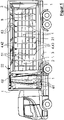
- the figure 1 shows a vehicle 3 in a vanishing perspective from the side, the frame-like structure 2 of which offers free spaces 21 on both longitudinal sides, which can be closed with tarpaulins 1.
- the tarpaulin 1 on the left in the direction of travel is open.
- the open area 21 on the right in the direction of travel, which is remote from the viewer, is closed with a tarpaulin 1 pretensioned according to the invention.
- Covers 51 which are aligned parallel to one another and are made of the same or similar, elastic plastic fabric as the tarpaulin 1, are welded onto the tarpaulin 1. They each form vertical pockets, in each of which a retaining strip 4 is inserted, which protrudes from the top and bottom of the pocket.
- a knife 8 can be seen above the wheels of the semi-trailer from the articulated lorry 3 that has been pierced into the right-hand tarpaulin 1 and has already left a cut there. Another cut of the knife 8 is, however, prevented by the retaining strip 4 behind the cover 51 against which the knife 8 just abuts.
- on the in figure 1 illustrated variant of a tarpaulin 1 according to the invention are additionally horizontal - welded straps made of flexible fabric - not specified. Although these straps can be severed by the knife 8 with an increased expenditure of cutting force and an additional expenditure of time for the reversing movement of the knife, this additional expenditure nevertheless inhibits the hasty incision of a nervous thief who is out for very quick prey.
- the figure 1 thus shows that the risk of an unwelcome cut with a knife 8 in the tarpaulin 1 is limited to narrow, vertical strips by means of the vertical retaining strips 4. Additional straps can be used to divide this strip into several rectangles, the diagonal of which will most likely limit the maximum length of an incision that is still likely.
- the upper ends 42 of the retaining strips 4 protrude from the covers 51 in the upper area of the structure 2 .
- Four black dots can be seen near the upper ends 42 . Two of them represent the - in figure 1 unspecified - represents screws 7, which are connected to a short textile belt 63.
- the two other dots represent two pieces of openings 9, but on the scale of the overview drawing figure 1 are hardly recognizable and therefore not labeled. These openings 9 are in the figure 4 shown on an enlarged scale.
- the figure 1 shows an example of the open tarpaulin 1 pushed together on the left that each textile belt 63 hangs on a guide roller 62. All guide rollers 62 can be moved horizontally within the rail 22 and thus enable the tarpaulin 1 to be opened and closed easily. In order to make the guide rollers 62 visible, figure 1 the rail 22 cut open in the drawing.
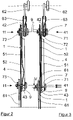
- the figure 2 shows a cross section through an open tarpaulin 1 with a not (yet) stretched retaining strip 4.
- the figure 3 in the closed and thus stretched state of the tarpaulin 1.
- the vertically aligned components such as the tarpaulin 1, the intermediate layer 52, the retaining strip 4 and the cover 51 are compressed in length and drawn apart in width.
- the small parts and other components on the two screws 7 are shown laterally pulled apart to such an extent that they no longer touch. The nuts on the screws 7 must therefore still be tightened before actual use.
- a screw 7 connects the retaining strip 4 at its upper end 42 through openings 9 both to the tarpaulin 1 and to the textile belt 63. Another screw 7 connects the lower end 43 of the retaining strip 4 through other openings 9 to the the tarpaulin 1 and the clamping lever 61.
- the retaining strip 4 is therefore only connected to the tarpaulin 1 at two locations.
- the connection locations on the retaining strip 4 are its two connection points 41.
- the connection locations on the tarpaulin 1 are the two fastening areas 11. In Figure 2 and Figure 3 each of these connection points is indicated by an arrow. This makes it easy to see that in the slack state the distance between the connection points on the tarpaulin 1 is smaller than the distance between the connection points on the retaining strip 4.
- the figure 3 shows the identical cross section through the tarpaulin 1 as in figure 2 , but in the closed and thus clamped state.
- the upper attachment portion 11 of the tarpaulin 1 and the complementary upper connection point 41 of the retaining strip 4 with the textile belt 63 and the guide rollers 62 are in the Figures 2 and 3 shown at exactly the same height, which is emphasized by a dot-dash line through the guide rollers 62.
- the Figures 2 and 3 present a surprisingly simple embodiment of the adjustment element according to the invention as a solution to this problem.
- the screw 7 protrudes through a first opening 9 in the retaining strip 4 and a second opening 9 in the tarpaulin 1 therethrough.
- a further opening 9 is introduced in the holding strip 4 above and below the two openings 9 that are in use in the illustrated state. These further openings 9 are shown in black on the cross section of the retaining strips 4 as small white ones recognizable rectangles. You are in the operating state of the Figures 2 and 3 the still unused part of the adjustment element according to the invention, which is waiting for later use.
- An essential advantage of this embodiment of the inventive adjustment element is that the additional openings 9 in the production of the retaining strip 4 require only extremely little additional effort.
- the figure 4 shows the embodiment of Figures 2 and 3 in the front view of the upper end 42 of a retaining strip 4.
- two openings 9 are arranged side by side, through which two screws 7 are then passed.
- two further openings 9 are drilled out of the retaining strip 4, punched out or cut out. They are in operating condition according to figure 4 , as well as with the Figures 2 and 3 still unused and waiting to be used at a later date.
- FIGS. 5 to 7 show embodiments of the inventive adjustment element in the form of elongated holes as an opening 9, in which the screw 7 only loosened, but not loosened at a sufficient length of the screw 7.
- the upper end 42 of a retaining strip 4 has only a single opening 9 in the form of an elongated hole.
- Three bulges 44 are formed in its left longitudinal side.
- the shank of a screw 7 snaps into one of them.
- the screw 7 has already been pushed out of the lower bulge 44 initially used as the connection point 41 and into the middle bulge 44 for the purpose of a first increase in the prestressing of the tarpaulin 1 . It can be tightened again by pushing the screw 7 into the highest bulge 7 .
- the merit of the embodiment according to figure 5 is that the prestressing of the tarpaulin 1 can be increased twice in its closed state without necessarily having to loosen the screw connection 7.
- the opening 9 is an elongated hole, in each of which two longitudinal edges parallel to one another a row of teeth 45 is formed.
- a row of teeth 45 is formed.
- the two opposing teeth of a perforated plate 46 are the two opposing teeth of a perforated plate 46, through the central opening of which a screw 7 can be inserted.
- the screw connection 7 only has to be loosened to such an extent that the perforated plate 46 can be lifted out of the rows of teeth 45 and reinserted in a higher position. In this position, the perforated plate 46 is pressed onto it by sufficiently large support plates 72 and washers 73 on the shank of the screw 7 or held by widenings 71 of the head of the screw 7.
- the advantage of this variant is that the preload can be increased very finely.
- the opening 9 has a row of teeth 45 on only one edge, on which a toothed wheel 74 rolls.
- the gearwheel 74 can be turned by means of a pivoting lever 75 and thereby lowers the retaining strip 4 further and further.
- the gear wheel 74 is pivoted on a small intermediate plate on which are fixed or molded two small slides 76 which slide on the smooth edge of the opening 9 and bear against it.
- the intermediate plate and a washer 73 are then placed on the shank of the screw 7 and take the gear wheel 74 in the middle like pliers, so that it continues to mesh with the row of teeth 74 when the preload is adjusted and does not jump out of it.
- the aim of the invention is achieved, namely to pretension the elastic tarpaulin 1 in the closed state even after a longer period of operation by stretching it by an increased path V, so that the tarpaulin 1 has an unchanged high resistance to lateral forces even in old age applies, which relieves the retaining strips 4 significantly. Thanks to this pretensioning, the resulting load will be distributed both to the tarpaulin 1 itself and to the retaining strips 4 even after prolonged use of the tarpaulin 1, for example if a load slips and hits the tarpaulin 1. In the ideal case, both elements will still be equally involved in the transfer of these forces to the structure 2.
- the retaining strips 4 can be dimensioned to be weaker because the prestressed tarpaulin 1 takes some of the load off them and carries it along. This reduces material costs and weight.
- the supporting effect of the supporting tarpaulin 1 achieves greater overall strength, i.e. improved securing of, for example, loosened cargo.
- An advantageous side effect of the pre-tensioning is that the fluttering of the tarpaulin 1 due to the relative wind is reduced when driving, which postpones the fatigue of the material from changing loads to a much later point in time, i.e. extends the service life of the tarpaulin 1.
- connection points 41 and the fastening areas 11 are designed as an opening 9 through which screws 7 are passed.
- a widening 71 is formed on each screw 7 . It presses the cover 51 onto the lower end 43 of the retaining strip 4. This in turn is pressed onto the tarpaulin 1 via the intermediate layer 52. From the other side of the tarpaulin 1, the nut presses a washer 73 onto the screw 7 either directly or by means of the visible part of the clamping lever 61 to the tarpaulin 1.
- This Metal elements significantly increase the effective pressure area on the textile components and thus increase the safety of the screw connection 7.
- the widening 71 presses the textile strap 63 onto a “support plate 72”, which in turn is supported on an adjacent section of the textile strap 63 with its other side.
- the support plate 72 preferably has a flat underside with straight edges around which the textile belt 63 is folded so that it rests flat on it. With its friction on the surfaces of the support plate 72, it relieves the holes in the textile belt 63 for the passage of the screws 7 from absorbing the tensile forces when the retaining strip 4 is loaded.
Landscapes
- Engineering & Computer Science (AREA)
- Mechanical Engineering (AREA)
- Transportation (AREA)
- Tents Or Canopies (AREA)
Applications Claiming Priority (1)
| Application Number | Priority Date | Filing Date | Title |
|---|---|---|---|
| DE102020005379.3A DE102020005379B4 (de) | 2020-09-02 | 2020-09-02 | Plane mit justierbarer Vorspannung und Haltestreifen als Sicherung gegen Einschneiden und mechanische Überlastung |
Publications (2)
| Publication Number | Publication Date |
|---|---|
| EP4005839A1 true EP4005839A1 (fr) | 2022-06-01 |
| EP4005839B1 EP4005839B1 (fr) | 2022-12-07 |
Family
ID=80221338
Family Applications (1)
| Application Number | Title | Priority Date | Filing Date |
|---|---|---|---|
| EP21000251.5A Active EP4005839B1 (fr) | 2020-09-02 | 2021-09-02 | Bâche à précontrainte pouvant être ajustée et bandes de maintien en tant que protection contre les coupures et les surcharges mécaniques |
Country Status (3)
| Country | Link |
|---|---|
| EP (1) | EP4005839B1 (fr) |
| DE (1) | DE102020005379B4 (fr) |
| PL (1) | PL4005839T3 (fr) |
Families Citing this family (1)
| Publication number | Priority date | Publication date | Assignee | Title |
|---|---|---|---|---|
| CN115104564B (zh) * | 2022-07-25 | 2024-05-10 | 罗耀明 | 一种用于黄条鰤深水养殖用网箱设备 |
Citations (3)
| Publication number | Priority date | Publication date | Assignee | Title |
|---|---|---|---|---|
| DE3345970A1 (de) * | 1983-12-20 | 1985-06-27 | Schröder Fahrzeug-Technik GmbH, 2964 Wiesmoor | Schiebeplane zur abdeckung eines transportfahrzeugs |
| DE102017001675A1 (de) * | 2017-02-22 | 2018-08-23 | Thorald Keim | Plane mit elastischen Verstärkungsgurten und Sicherungselementen |
| BE1027081A1 (nl) * | 2019-02-27 | 2020-09-18 | Versus Omega Bvba | Opstaande versteviging |
Family Cites Families (6)
| Publication number | Priority date | Publication date | Assignee | Title |
|---|---|---|---|---|
| DE10150102A1 (de) | 2001-09-14 | 2003-04-03 | Gerhard Vitt | Abdeckplane |
| FR2832366B1 (fr) | 2001-11-19 | 2004-03-12 | Fair Internat | Dispositif de tension pour paroi souple de vehicule de transport |
| ITPD20050085U1 (it) | 2005-10-20 | 2007-04-21 | Plastiveneta Spa | Struttura di tessuto spalmato |
| FR2903935B1 (fr) | 2006-07-18 | 2010-11-12 | F A I R Internat | Paroi souple securisee de type bache, en particulier pour carrosserie de vehicule |
| DE102016011006B4 (de) | 2016-09-14 | 2020-08-06 | Thorald Keim | Plane mit gewebten Gurtbändern und integriertem Draht |
| DE202018103500U1 (de) | 2018-06-21 | 2018-10-31 | Roland International B.V. | Verbindungsorgan oder Gurtspanner für ein Verdeck auf einem Fahrzeug zur Beförderung von Lasten und Verdeck |
-
2020
- 2020-09-02 DE DE102020005379.3A patent/DE102020005379B4/de active Active
-
2021
- 2021-09-02 EP EP21000251.5A patent/EP4005839B1/fr active Active
- 2021-09-02 PL PL21000251.5T patent/PL4005839T3/pl unknown
Patent Citations (3)
| Publication number | Priority date | Publication date | Assignee | Title |
|---|---|---|---|---|
| DE3345970A1 (de) * | 1983-12-20 | 1985-06-27 | Schröder Fahrzeug-Technik GmbH, 2964 Wiesmoor | Schiebeplane zur abdeckung eines transportfahrzeugs |
| DE102017001675A1 (de) * | 2017-02-22 | 2018-08-23 | Thorald Keim | Plane mit elastischen Verstärkungsgurten und Sicherungselementen |
| BE1027081A1 (nl) * | 2019-02-27 | 2020-09-18 | Versus Omega Bvba | Opstaande versteviging |
Also Published As
| Publication number | Publication date |
|---|---|
| DE102020005379B4 (de) | 2023-05-25 |
| EP4005839B1 (fr) | 2022-12-07 |
| PL4005839T3 (pl) | 2023-01-16 |
| DE102020005379A1 (de) | 2022-03-03 |
Similar Documents
| Publication | Publication Date | Title |
|---|---|---|
| DE19739919C2 (de) | Sonnenrollo für ein Kraftfahrzeugdach | |
| EP2794997B1 (fr) | Structure de protection | |
| DE102017001675B4 (de) | Plane mit elastischen Verstärkungsgurten und Sicherungselementen | |
| EP4005839B1 (fr) | Bâche à précontrainte pouvant être ajustée et bandes de maintien en tant que protection contre les coupures et les surcharges mécaniques | |
| DE202008008651U1 (de) | Nutzfahrzeug-Aufbau und Halteelement für einen Nutzfahrzeug-Aufbau | |
| DE19504700A1 (de) | Tor, insbesondere Deckensektionaltor | |
| EP0389831B1 (fr) | Dispositif pour ligaturer des éléments allongés | |
| EP3106333B1 (fr) | Carrosserie de vehicule, en particulier pour vehicules utilitaires, vehicule utilitaire comprenant une telle carrosserie et procede de fabrication | |
| DE2637997A1 (de) | Gitter fuer ein sieb | |
| DE69706497T2 (de) | Hagelschutz | |
| EP0919117A1 (fr) | Transporteur incliné pour machines de récolte agricoles | |
| EP3666567B1 (fr) | Rideau latéral pour camion-remorque, camion-remorque et camion avec camion-remorque | |
| EP2428397B1 (fr) | Rail de profilé perforé | |
| DE3318174C2 (fr) | ||
| DE2638099C2 (de) | Lademulde, vorzugsweise für Schüttgut wie Erze oder Schlagschotter | |
| EP3309299B1 (fr) | Ouvrage de protection | |
| EP3064385A1 (fr) | Structure de vehicule dotée d'une bache coulissante | |
| DE102019132564B4 (de) | Positioniereinrichtung und Sonnen-oder Blickschutzeinrichtung mit einer solchen Positioniereinrichtung | |
| DE3348204C2 (en) | Frame for belt conveyor apparatuses | |
| DE112008002875B4 (de) | Versteifungselement für die Fahrzeugkarosserie | |
| DE102018104706A1 (de) | Auffahrschiene | |
| DE202025101895U1 (de) | Abdeckung für ein Kraftfahrzeug | |
| EP3162960A1 (fr) | Systeme de frein a cable | |
| DE202021103605U1 (de) | Zaunelement | |
| DE1534539C (de) | Blendschutzzaun |
Legal Events
| Date | Code | Title | Description |
|---|---|---|---|
| PUAI | Public reference made under article 153(3) epc to a published international application that has entered the european phase |
Free format text: ORIGINAL CODE: 0009012 |
|
| STAA | Information on the status of an ep patent application or granted ep patent |
Free format text: STATUS: THE APPLICATION HAS BEEN PUBLISHED |
|
| STAA | Information on the status of an ep patent application or granted ep patent |
Free format text: STATUS: REQUEST FOR EXAMINATION WAS MADE |
|
| AK | Designated contracting states |
Kind code of ref document: A1 Designated state(s): AL AT BE BG CH CY CZ DE DK EE ES FI FR GB GR HR HU IE IS IT LI LT LU LV MC MK MT NL NO PL PT RO RS SE SI SK SM TR |
|
| 17P | Request for examination filed |
Effective date: 20220519 |
|
| RBV | Designated contracting states (corrected) |
Designated state(s): AL AT BE BG CH CY CZ DE DK EE ES FI FR GB GR HR HU IE IS IT LI LT LU LV MC MK MT NL NO PL PT RO RS SE SI SK SM TR |
|
| GRAP | Despatch of communication of intention to grant a patent |
Free format text: ORIGINAL CODE: EPIDOSNIGR1 |
|
| STAA | Information on the status of an ep patent application or granted ep patent |
Free format text: STATUS: GRANT OF PATENT IS INTENDED |
|
| GRAS | Grant fee paid |
Free format text: ORIGINAL CODE: EPIDOSNIGR3 |
|
| INTG | Intention to grant announced |
Effective date: 20220920 |
|
| GRAA | (expected) grant |
Free format text: ORIGINAL CODE: 0009210 |
|
| STAA | Information on the status of an ep patent application or granted ep patent |
Free format text: STATUS: THE PATENT HAS BEEN GRANTED |
|
| AK | Designated contracting states |
Kind code of ref document: B1 Designated state(s): AL AT BE BG CH CY CZ DE DK EE ES FI FR GB GR HR HU IE IS IT LI LT LU LV MC MK MT NL NO PL PT RO RS SE SI SK SM TR |
|
| REG | Reference to a national code |
Ref country code: GB Ref legal event code: FG4D Free format text: NOT ENGLISH |
|
| REG | Reference to a national code |
Ref country code: CH Ref legal event code: EP Ref country code: AT Ref legal event code: REF Ref document number: 1536099 Country of ref document: AT Kind code of ref document: T Effective date: 20221215 |
|
| REG | Reference to a national code |
Ref country code: DE Ref legal event code: R096 Ref document number: 502021000293 Country of ref document: DE |
|
| REG | Reference to a national code |
Ref country code: NL Ref legal event code: FP Ref country code: IE Ref legal event code: FG4D Free format text: LANGUAGE OF EP DOCUMENT: GERMAN |
|
| REG | Reference to a national code |
Ref country code: LT Ref legal event code: MG9D |
|
| PG25 | Lapsed in a contracting state [announced via postgrant information from national office to epo] |
Ref country code: SE Free format text: LAPSE BECAUSE OF FAILURE TO SUBMIT A TRANSLATION OF THE DESCRIPTION OR TO PAY THE FEE WITHIN THE PRESCRIBED TIME-LIMIT Effective date: 20221207 Ref country code: NO Free format text: LAPSE BECAUSE OF FAILURE TO SUBMIT A TRANSLATION OF THE DESCRIPTION OR TO PAY THE FEE WITHIN THE PRESCRIBED TIME-LIMIT Effective date: 20230307 Ref country code: LT Free format text: LAPSE BECAUSE OF FAILURE TO SUBMIT A TRANSLATION OF THE DESCRIPTION OR TO PAY THE FEE WITHIN THE PRESCRIBED TIME-LIMIT Effective date: 20221207 Ref country code: FI Free format text: LAPSE BECAUSE OF FAILURE TO SUBMIT A TRANSLATION OF THE DESCRIPTION OR TO PAY THE FEE WITHIN THE PRESCRIBED TIME-LIMIT Effective date: 20221207 Ref country code: ES Free format text: LAPSE BECAUSE OF FAILURE TO SUBMIT A TRANSLATION OF THE DESCRIPTION OR TO PAY THE FEE WITHIN THE PRESCRIBED TIME-LIMIT Effective date: 20221207 |
|
| PG25 | Lapsed in a contracting state [announced via postgrant information from national office to epo] |
Ref country code: RS Free format text: LAPSE BECAUSE OF FAILURE TO SUBMIT A TRANSLATION OF THE DESCRIPTION OR TO PAY THE FEE WITHIN THE PRESCRIBED TIME-LIMIT Effective date: 20221207 Ref country code: LV Free format text: LAPSE BECAUSE OF FAILURE TO SUBMIT A TRANSLATION OF THE DESCRIPTION OR TO PAY THE FEE WITHIN THE PRESCRIBED TIME-LIMIT Effective date: 20221207 Ref country code: HR Free format text: LAPSE BECAUSE OF FAILURE TO SUBMIT A TRANSLATION OF THE DESCRIPTION OR TO PAY THE FEE WITHIN THE PRESCRIBED TIME-LIMIT Effective date: 20221207 Ref country code: GR Free format text: LAPSE BECAUSE OF FAILURE TO SUBMIT A TRANSLATION OF THE DESCRIPTION OR TO PAY THE FEE WITHIN THE PRESCRIBED TIME-LIMIT Effective date: 20230308 |
|
| PG25 | Lapsed in a contracting state [announced via postgrant information from national office to epo] |
Ref country code: SM Free format text: LAPSE BECAUSE OF FAILURE TO SUBMIT A TRANSLATION OF THE DESCRIPTION OR TO PAY THE FEE WITHIN THE PRESCRIBED TIME-LIMIT Effective date: 20221207 Ref country code: RO Free format text: LAPSE BECAUSE OF FAILURE TO SUBMIT A TRANSLATION OF THE DESCRIPTION OR TO PAY THE FEE WITHIN THE PRESCRIBED TIME-LIMIT Effective date: 20221207 Ref country code: PT Free format text: LAPSE BECAUSE OF FAILURE TO SUBMIT A TRANSLATION OF THE DESCRIPTION OR TO PAY THE FEE WITHIN THE PRESCRIBED TIME-LIMIT Effective date: 20230410 Ref country code: EE Free format text: LAPSE BECAUSE OF FAILURE TO SUBMIT A TRANSLATION OF THE DESCRIPTION OR TO PAY THE FEE WITHIN THE PRESCRIBED TIME-LIMIT Effective date: 20221207 Ref country code: CZ Free format text: LAPSE BECAUSE OF FAILURE TO SUBMIT A TRANSLATION OF THE DESCRIPTION OR TO PAY THE FEE WITHIN THE PRESCRIBED TIME-LIMIT Effective date: 20221207 |
|
| PG25 | Lapsed in a contracting state [announced via postgrant information from national office to epo] |
Ref country code: SK Free format text: LAPSE BECAUSE OF FAILURE TO SUBMIT A TRANSLATION OF THE DESCRIPTION OR TO PAY THE FEE WITHIN THE PRESCRIBED TIME-LIMIT Effective date: 20221207 Ref country code: IS Free format text: LAPSE BECAUSE OF FAILURE TO SUBMIT A TRANSLATION OF THE DESCRIPTION OR TO PAY THE FEE WITHIN THE PRESCRIBED TIME-LIMIT Effective date: 20230407 Ref country code: AL Free format text: LAPSE BECAUSE OF FAILURE TO SUBMIT A TRANSLATION OF THE DESCRIPTION OR TO PAY THE FEE WITHIN THE PRESCRIBED TIME-LIMIT Effective date: 20221207 |
|
| REG | Reference to a national code |
Ref country code: DE Ref legal event code: R097 Ref document number: 502021000293 Country of ref document: DE |
|
| PLBE | No opposition filed within time limit |
Free format text: ORIGINAL CODE: 0009261 |
|
| STAA | Information on the status of an ep patent application or granted ep patent |
Free format text: STATUS: NO OPPOSITION FILED WITHIN TIME LIMIT |
|
| PG25 | Lapsed in a contracting state [announced via postgrant information from national office to epo] |
Ref country code: DK Free format text: LAPSE BECAUSE OF FAILURE TO SUBMIT A TRANSLATION OF THE DESCRIPTION OR TO PAY THE FEE WITHIN THE PRESCRIBED TIME-LIMIT Effective date: 20221207 |
|
| 26N | No opposition filed |
Effective date: 20230908 |
|
| PG25 | Lapsed in a contracting state [announced via postgrant information from national office to epo] |
Ref country code: SI Free format text: LAPSE BECAUSE OF FAILURE TO SUBMIT A TRANSLATION OF THE DESCRIPTION OR TO PAY THE FEE WITHIN THE PRESCRIBED TIME-LIMIT Effective date: 20221207 |
|
| PG25 | Lapsed in a contracting state [announced via postgrant information from national office to epo] |
Ref country code: LU Free format text: LAPSE BECAUSE OF NON-PAYMENT OF DUE FEES Effective date: 20230902 |
|
| REG | Reference to a national code |
Ref country code: BE Ref legal event code: MM Effective date: 20230930 |
|
| PG25 | Lapsed in a contracting state [announced via postgrant information from national office to epo] |
Ref country code: LU Free format text: LAPSE BECAUSE OF NON-PAYMENT OF DUE FEES Effective date: 20230902 Ref country code: IT Free format text: LAPSE BECAUSE OF FAILURE TO SUBMIT A TRANSLATION OF THE DESCRIPTION OR TO PAY THE FEE WITHIN THE PRESCRIBED TIME-LIMIT Effective date: 20221207 Ref country code: MC Free format text: LAPSE BECAUSE OF FAILURE TO SUBMIT A TRANSLATION OF THE DESCRIPTION OR TO PAY THE FEE WITHIN THE PRESCRIBED TIME-LIMIT Effective date: 20221207 |
|
| REG | Reference to a national code |
Ref country code: IE Ref legal event code: MM4A |
|
| PG25 | Lapsed in a contracting state [announced via postgrant information from national office to epo] |
Ref country code: IE Free format text: LAPSE BECAUSE OF NON-PAYMENT OF DUE FEES Effective date: 20230902 |
|
| PG25 | Lapsed in a contracting state [announced via postgrant information from national office to epo] |
Ref country code: IE Free format text: LAPSE BECAUSE OF NON-PAYMENT OF DUE FEES Effective date: 20230902 |
|
| PG25 | Lapsed in a contracting state [announced via postgrant information from national office to epo] |
Ref country code: BE Free format text: LAPSE BECAUSE OF NON-PAYMENT OF DUE FEES Effective date: 20230930 |
|
| PG25 | Lapsed in a contracting state [announced via postgrant information from national office to epo] |
Ref country code: BG Free format text: LAPSE BECAUSE OF FAILURE TO SUBMIT A TRANSLATION OF THE DESCRIPTION OR TO PAY THE FEE WITHIN THE PRESCRIBED TIME-LIMIT Effective date: 20221207 |
|
| PG25 | Lapsed in a contracting state [announced via postgrant information from national office to epo] |
Ref country code: BG Free format text: LAPSE BECAUSE OF FAILURE TO SUBMIT A TRANSLATION OF THE DESCRIPTION OR TO PAY THE FEE WITHIN THE PRESCRIBED TIME-LIMIT Effective date: 20221207 |
|
| PG25 | Lapsed in a contracting state [announced via postgrant information from national office to epo] |
Ref country code: CY Free format text: LAPSE BECAUSE OF FAILURE TO SUBMIT A TRANSLATION OF THE DESCRIPTION OR TO PAY THE FEE WITHIN THE PRESCRIBED TIME-LIMIT; INVALID AB INITIO Effective date: 20210902 |
|
| PG25 | Lapsed in a contracting state [announced via postgrant information from national office to epo] |
Ref country code: HU Free format text: LAPSE BECAUSE OF FAILURE TO SUBMIT A TRANSLATION OF THE DESCRIPTION OR TO PAY THE FEE WITHIN THE PRESCRIBED TIME-LIMIT; INVALID AB INITIO Effective date: 20210902 |
|
| REG | Reference to a national code |
Ref country code: CH Ref legal event code: U11 Free format text: ST27 STATUS EVENT CODE: U-0-0-U10-U11 (AS PROVIDED BY THE NATIONAL OFFICE) Effective date: 20251001 |
|
| PGFP | Annual fee paid to national office [announced via postgrant information from national office to epo] |
Ref country code: DE Payment date: 20250901 Year of fee payment: 5 |
|
| PGFP | Annual fee paid to national office [announced via postgrant information from national office to epo] |
Ref country code: TR Payment date: 20250805 Year of fee payment: 5 Ref country code: PL Payment date: 20250831 Year of fee payment: 5 Ref country code: NL Payment date: 20250903 Year of fee payment: 5 |
|
| PGFP | Annual fee paid to national office [announced via postgrant information from national office to epo] |
Ref country code: GB Payment date: 20250905 Year of fee payment: 5 |
|
| PGFP | Annual fee paid to national office [announced via postgrant information from national office to epo] |
Ref country code: AT Payment date: 20251020 Year of fee payment: 5 Ref country code: FR Payment date: 20250909 Year of fee payment: 5 |
|
| PGFP | Annual fee paid to national office [announced via postgrant information from national office to epo] |
Ref country code: CH Payment date: 20251001 Year of fee payment: 5 |