EP4005848A1 - Elektrofahrzeug - Google Patents
Elektrofahrzeug Download PDFInfo
- Publication number
- EP4005848A1 EP4005848A1 EP20843073.6A EP20843073A EP4005848A1 EP 4005848 A1 EP4005848 A1 EP 4005848A1 EP 20843073 A EP20843073 A EP 20843073A EP 4005848 A1 EP4005848 A1 EP 4005848A1
- Authority
- EP
- European Patent Office
- Prior art keywords
- power
- voltage
- output
- power converter
- line
- Prior art date
- Legal status (The legal status is an assumption and is not a legal conclusion. Google has not performed a legal analysis and makes no representation as to the accuracy of the status listed.)
- Pending
Links
Images






Classifications
-
- B—PERFORMING OPERATIONS; TRANSPORTING
- B60—VEHICLES IN GENERAL
- B60L—PROPULSION OF ELECTRICALLY-PROPELLED VEHICLES; SUPPLYING ELECTRIC POWER FOR AUXILIARY EQUIPMENT OF ELECTRICALLY-PROPELLED VEHICLES; ELECTRODYNAMIC BRAKE SYSTEMS FOR VEHICLES IN GENERAL; MAGNETIC SUSPENSION OR LEVITATION FOR VEHICLES; MONITORING OPERATING VARIABLES OF ELECTRICALLY-PROPELLED VEHICLES; ELECTRIC SAFETY DEVICES FOR ELECTRICALLY-PROPELLED VEHICLES
- B60L50/00—Electric propulsion with power supplied within the vehicle
- B60L50/50—Electric propulsion with power supplied within the vehicle using propulsion power supplied by batteries or fuel cells
- B60L50/60—Electric propulsion with power supplied within the vehicle using propulsion power supplied by batteries or fuel cells using power supplied by batteries
- B60L50/61—Electric propulsion with power supplied within the vehicle using propulsion power supplied by batteries or fuel cells using power supplied by batteries by batteries charged by engine-driven generators, e.g. series hybrid electric vehicles
-
- B—PERFORMING OPERATIONS; TRANSPORTING
- B60—VEHICLES IN GENERAL
- B60K—ARRANGEMENT OR MOUNTING OF PROPULSION UNITS OR OF TRANSMISSIONS IN VEHICLES; ARRANGEMENT OR MOUNTING OF PLURAL DIVERSE PRIME-MOVERS IN VEHICLES; AUXILIARY DRIVES FOR VEHICLES; INSTRUMENTATION OR DASHBOARDS FOR VEHICLES; ARRANGEMENTS IN CONNECTION WITH COOLING, AIR INTAKE, GAS EXHAUST OR FUEL SUPPLY OF PROPULSION UNITS IN VEHICLES
- B60K6/00—Arrangement or mounting of plural diverse prime-movers for mutual or common propulsion, e.g. hybrid propulsion systems comprising electric motors and internal combustion engines
- B60K6/20—Arrangement or mounting of plural diverse prime-movers for mutual or common propulsion, e.g. hybrid propulsion systems comprising electric motors and internal combustion engines the prime-movers consisting of electric motors and internal combustion engines, e.g. HEVs
- B60K6/42—Arrangement or mounting of plural diverse prime-movers for mutual or common propulsion, e.g. hybrid propulsion systems comprising electric motors and internal combustion engines the prime-movers consisting of electric motors and internal combustion engines, e.g. HEVs characterised by the architecture of the hybrid electric vehicle
- B60K6/46—Series type
-
- H—ELECTRICITY
- H02—GENERATION; CONVERSION OR DISTRIBUTION OF ELECTRIC POWER
- H02M—APPARATUS FOR CONVERSION BETWEEN AC AND AC, BETWEEN AC AND DC, OR BETWEEN DC AND DC, AND FOR USE WITH MAINS OR SIMILAR POWER SUPPLY SYSTEMS; CONVERSION OF DC OR AC INPUT POWER INTO SURGE OUTPUT POWER; CONTROL OR REGULATION THEREOF
- H02M1/00—Details of apparatus for conversion
- H02M1/32—Means for protecting converters other than automatic disconnection
- H02M1/327—Means for protecting converters other than automatic disconnection against abnormal temperatures
-
- B—PERFORMING OPERATIONS; TRANSPORTING
- B60—VEHICLES IN GENERAL
- B60L—PROPULSION OF ELECTRICALLY-PROPELLED VEHICLES; SUPPLYING ELECTRIC POWER FOR AUXILIARY EQUIPMENT OF ELECTRICALLY-PROPELLED VEHICLES; ELECTRODYNAMIC BRAKE SYSTEMS FOR VEHICLES IN GENERAL; MAGNETIC SUSPENSION OR LEVITATION FOR VEHICLES; MONITORING OPERATING VARIABLES OF ELECTRICALLY-PROPELLED VEHICLES; ELECTRIC SAFETY DEVICES FOR ELECTRICALLY-PROPELLED VEHICLES
- B60L1/00—Supplying electric power to auxiliary equipment of vehicles
- B60L1/003—Supplying electric power to auxiliary equipment of vehicles to auxiliary motors, e.g. for pumps, compressors
-
- B—PERFORMING OPERATIONS; TRANSPORTING
- B60—VEHICLES IN GENERAL
- B60L—PROPULSION OF ELECTRICALLY-PROPELLED VEHICLES; SUPPLYING ELECTRIC POWER FOR AUXILIARY EQUIPMENT OF ELECTRICALLY-PROPELLED VEHICLES; ELECTRODYNAMIC BRAKE SYSTEMS FOR VEHICLES IN GENERAL; MAGNETIC SUSPENSION OR LEVITATION FOR VEHICLES; MONITORING OPERATING VARIABLES OF ELECTRICALLY-PROPELLED VEHICLES; ELECTRIC SAFETY DEVICES FOR ELECTRICALLY-PROPELLED VEHICLES
- B60L15/00—Methods, circuits, or devices for controlling the traction-motor speed of electrically-propelled vehicles
- B60L15/20—Methods, circuits, or devices for controlling the traction-motor speed of electrically-propelled vehicles for control of the vehicle or its driving motor to achieve a desired performance, e.g. speed, torque, programmed variation of speed
- B60L15/2009—Methods, circuits, or devices for controlling the traction-motor speed of electrically-propelled vehicles for control of the vehicle or its driving motor to achieve a desired performance, e.g. speed, torque, programmed variation of speed for braking
-
- B—PERFORMING OPERATIONS; TRANSPORTING
- B60—VEHICLES IN GENERAL
- B60L—PROPULSION OF ELECTRICALLY-PROPELLED VEHICLES; SUPPLYING ELECTRIC POWER FOR AUXILIARY EQUIPMENT OF ELECTRICALLY-PROPELLED VEHICLES; ELECTRODYNAMIC BRAKE SYSTEMS FOR VEHICLES IN GENERAL; MAGNETIC SUSPENSION OR LEVITATION FOR VEHICLES; MONITORING OPERATING VARIABLES OF ELECTRICALLY-PROPELLED VEHICLES; ELECTRIC SAFETY DEVICES FOR ELECTRICALLY-PROPELLED VEHICLES
- B60L15/00—Methods, circuits, or devices for controlling the traction-motor speed of electrically-propelled vehicles
- B60L15/20—Methods, circuits, or devices for controlling the traction-motor speed of electrically-propelled vehicles for control of the vehicle or its driving motor to achieve a desired performance, e.g. speed, torque, programmed variation of speed
- B60L15/2045—Methods, circuits, or devices for controlling the traction-motor speed of electrically-propelled vehicles for control of the vehicle or its driving motor to achieve a desired performance, e.g. speed, torque, programmed variation of speed for optimising the use of energy
-
- B—PERFORMING OPERATIONS; TRANSPORTING
- B60—VEHICLES IN GENERAL
- B60L—PROPULSION OF ELECTRICALLY-PROPELLED VEHICLES; SUPPLYING ELECTRIC POWER FOR AUXILIARY EQUIPMENT OF ELECTRICALLY-PROPELLED VEHICLES; ELECTRODYNAMIC BRAKE SYSTEMS FOR VEHICLES IN GENERAL; MAGNETIC SUSPENSION OR LEVITATION FOR VEHICLES; MONITORING OPERATING VARIABLES OF ELECTRICALLY-PROPELLED VEHICLES; ELECTRIC SAFETY DEVICES FOR ELECTRICALLY-PROPELLED VEHICLES
- B60L3/00—Electric devices on electrically-propelled vehicles for safety purposes; Monitoring operating variables, e.g. speed, deceleration or energy consumption
- B60L3/0023—Detecting, eliminating, remedying or compensating for drive train abnormalities, e.g. failures within the drive train
- B60L3/003—Detecting, eliminating, remedying or compensating for drive train abnormalities, e.g. failures within the drive train relating to inverters
-
- B—PERFORMING OPERATIONS; TRANSPORTING
- B60—VEHICLES IN GENERAL
- B60L—PROPULSION OF ELECTRICALLY-PROPELLED VEHICLES; SUPPLYING ELECTRIC POWER FOR AUXILIARY EQUIPMENT OF ELECTRICALLY-PROPELLED VEHICLES; ELECTRODYNAMIC BRAKE SYSTEMS FOR VEHICLES IN GENERAL; MAGNETIC SUSPENSION OR LEVITATION FOR VEHICLES; MONITORING OPERATING VARIABLES OF ELECTRICALLY-PROPELLED VEHICLES; ELECTRIC SAFETY DEVICES FOR ELECTRICALLY-PROPELLED VEHICLES
- B60L3/00—Electric devices on electrically-propelled vehicles for safety purposes; Monitoring operating variables, e.g. speed, deceleration or energy consumption
- B60L3/04—Cutting off the power supply under fault conditions
-
- B—PERFORMING OPERATIONS; TRANSPORTING
- B60—VEHICLES IN GENERAL
- B60L—PROPULSION OF ELECTRICALLY-PROPELLED VEHICLES; SUPPLYING ELECTRIC POWER FOR AUXILIARY EQUIPMENT OF ELECTRICALLY-PROPELLED VEHICLES; ELECTRODYNAMIC BRAKE SYSTEMS FOR VEHICLES IN GENERAL; MAGNETIC SUSPENSION OR LEVITATION FOR VEHICLES; MONITORING OPERATING VARIABLES OF ELECTRICALLY-PROPELLED VEHICLES; ELECTRIC SAFETY DEVICES FOR ELECTRICALLY-PROPELLED VEHICLES
- B60L50/00—Electric propulsion with power supplied within the vehicle
- B60L50/10—Electric propulsion with power supplied within the vehicle using propulsion power supplied by engine-driven generators, e.g. generators driven by combustion engines
- B60L50/13—Electric propulsion with power supplied within the vehicle using propulsion power supplied by engine-driven generators, e.g. generators driven by combustion engines using AC generators and AC motors
-
- B—PERFORMING OPERATIONS; TRANSPORTING
- B60—VEHICLES IN GENERAL
- B60L—PROPULSION OF ELECTRICALLY-PROPELLED VEHICLES; SUPPLYING ELECTRIC POWER FOR AUXILIARY EQUIPMENT OF ELECTRICALLY-PROPELLED VEHICLES; ELECTRODYNAMIC BRAKE SYSTEMS FOR VEHICLES IN GENERAL; MAGNETIC SUSPENSION OR LEVITATION FOR VEHICLES; MONITORING OPERATING VARIABLES OF ELECTRICALLY-PROPELLED VEHICLES; ELECTRIC SAFETY DEVICES FOR ELECTRICALLY-PROPELLED VEHICLES
- B60L50/00—Electric propulsion with power supplied within the vehicle
- B60L50/10—Electric propulsion with power supplied within the vehicle using propulsion power supplied by engine-driven generators, e.g. generators driven by combustion engines
- B60L50/15—Electric propulsion with power supplied within the vehicle using propulsion power supplied by engine-driven generators, e.g. generators driven by combustion engines with additional electric power supply
-
- B—PERFORMING OPERATIONS; TRANSPORTING
- B60—VEHICLES IN GENERAL
- B60L—PROPULSION OF ELECTRICALLY-PROPELLED VEHICLES; SUPPLYING ELECTRIC POWER FOR AUXILIARY EQUIPMENT OF ELECTRICALLY-PROPELLED VEHICLES; ELECTRODYNAMIC BRAKE SYSTEMS FOR VEHICLES IN GENERAL; MAGNETIC SUSPENSION OR LEVITATION FOR VEHICLES; MONITORING OPERATING VARIABLES OF ELECTRICALLY-PROPELLED VEHICLES; ELECTRIC SAFETY DEVICES FOR ELECTRICALLY-PROPELLED VEHICLES
- B60L7/00—Electrodynamic brake systems for vehicles in general
- B60L7/10—Dynamic electric regenerative braking
- B60L7/14—Dynamic electric regenerative braking for vehicles propelled by AC motors
-
- B—PERFORMING OPERATIONS; TRANSPORTING
- B60—VEHICLES IN GENERAL
- B60L—PROPULSION OF ELECTRICALLY-PROPELLED VEHICLES; SUPPLYING ELECTRIC POWER FOR AUXILIARY EQUIPMENT OF ELECTRICALLY-PROPELLED VEHICLES; ELECTRODYNAMIC BRAKE SYSTEMS FOR VEHICLES IN GENERAL; MAGNETIC SUSPENSION OR LEVITATION FOR VEHICLES; MONITORING OPERATING VARIABLES OF ELECTRICALLY-PROPELLED VEHICLES; ELECTRIC SAFETY DEVICES FOR ELECTRICALLY-PROPELLED VEHICLES
- B60L7/00—Electrodynamic brake systems for vehicles in general
- B60L7/10—Dynamic electric regenerative braking
- B60L7/16—Dynamic electric regenerative braking for vehicles comprising converters between the power source and the motor
-
- B—PERFORMING OPERATIONS; TRANSPORTING
- B60—VEHICLES IN GENERAL
- B60L—PROPULSION OF ELECTRICALLY-PROPELLED VEHICLES; SUPPLYING ELECTRIC POWER FOR AUXILIARY EQUIPMENT OF ELECTRICALLY-PROPELLED VEHICLES; ELECTRODYNAMIC BRAKE SYSTEMS FOR VEHICLES IN GENERAL; MAGNETIC SUSPENSION OR LEVITATION FOR VEHICLES; MONITORING OPERATING VARIABLES OF ELECTRICALLY-PROPELLED VEHICLES; ELECTRIC SAFETY DEVICES FOR ELECTRICALLY-PROPELLED VEHICLES
- B60L7/00—Electrodynamic brake systems for vehicles in general
- B60L7/10—Dynamic electric regenerative braking
- B60L7/18—Controlling the braking effect
-
- B—PERFORMING OPERATIONS; TRANSPORTING
- B60—VEHICLES IN GENERAL
- B60L—PROPULSION OF ELECTRICALLY-PROPELLED VEHICLES; SUPPLYING ELECTRIC POWER FOR AUXILIARY EQUIPMENT OF ELECTRICALLY-PROPELLED VEHICLES; ELECTRODYNAMIC BRAKE SYSTEMS FOR VEHICLES IN GENERAL; MAGNETIC SUSPENSION OR LEVITATION FOR VEHICLES; MONITORING OPERATING VARIABLES OF ELECTRICALLY-PROPELLED VEHICLES; ELECTRIC SAFETY DEVICES FOR ELECTRICALLY-PROPELLED VEHICLES
- B60L7/00—Electrodynamic brake systems for vehicles in general
- B60L7/22—Dynamic electric resistor braking, combined with dynamic electric regenerative braking
-
- B—PERFORMING OPERATIONS; TRANSPORTING
- B60—VEHICLES IN GENERAL
- B60W—CONJOINT CONTROL OF VEHICLE SUB-UNITS OF DIFFERENT TYPE OR DIFFERENT FUNCTION; CONTROL SYSTEMS SPECIALLY ADAPTED FOR HYBRID VEHICLES; ROAD VEHICLE DRIVE CONTROL SYSTEMS FOR PURPOSES NOT RELATED TO THE CONTROL OF A PARTICULAR SUB-UNIT
- B60W10/00—Conjoint control of vehicle sub-units of different type or different function
- B60W10/04—Conjoint control of vehicle sub-units of different type or different function including control of propulsion units
- B60W10/08—Conjoint control of vehicle sub-units of different type or different function including control of propulsion units including control of electric propulsion units, e.g. motors or generators
-
- B—PERFORMING OPERATIONS; TRANSPORTING
- B60—VEHICLES IN GENERAL
- B60W—CONJOINT CONTROL OF VEHICLE SUB-UNITS OF DIFFERENT TYPE OR DIFFERENT FUNCTION; CONTROL SYSTEMS SPECIALLY ADAPTED FOR HYBRID VEHICLES; ROAD VEHICLE DRIVE CONTROL SYSTEMS FOR PURPOSES NOT RELATED TO THE CONTROL OF A PARTICULAR SUB-UNIT
- B60W10/00—Conjoint control of vehicle sub-units of different type or different function
- B60W10/24—Conjoint control of vehicle sub-units of different type or different function including control of energy storage means
- B60W10/26—Conjoint control of vehicle sub-units of different type or different function including control of energy storage means for electrical energy, e.g. batteries or capacitors
-
- B—PERFORMING OPERATIONS; TRANSPORTING
- B60—VEHICLES IN GENERAL
- B60W—CONJOINT CONTROL OF VEHICLE SUB-UNITS OF DIFFERENT TYPE OR DIFFERENT FUNCTION; CONTROL SYSTEMS SPECIALLY ADAPTED FOR HYBRID VEHICLES; ROAD VEHICLE DRIVE CONTROL SYSTEMS FOR PURPOSES NOT RELATED TO THE CONTROL OF A PARTICULAR SUB-UNIT
- B60W20/00—Control systems specially adapted for hybrid vehicles
- B60W20/10—Controlling the power contribution of each of the prime movers to meet required power demand
- B60W20/15—Control strategies specially adapted for achieving a particular effect
-
- H—ELECTRICITY
- H02—GENERATION; CONVERSION OR DISTRIBUTION OF ELECTRIC POWER
- H02J—ELECTRIC POWER NETWORKS; CIRCUIT ARRANGEMENTS OR SYSTEMS FOR SUPPLYING OR DISTRIBUTING ELECTRIC POWER; SYSTEMS FOR STORING ELECTRIC ENERGY
- H02J7/00—Circuit arrangements for charging or discharging batteries or for supplying loads from batteries
- H02J7/14—Circuit arrangements for charging or discharging batteries or for supplying loads from batteries for charging batteries from dynamo-electric generators driven at varying speed, e.g. on vehicle
- H02J7/143—Circuit arrangements for charging or discharging batteries or for supplying loads from batteries for charging batteries from dynamo-electric generators driven at varying speed, e.g. on vehicle with multiple generators
-
- H—ELECTRICITY
- H02—GENERATION; CONVERSION OR DISTRIBUTION OF ELECTRIC POWER
- H02J—ELECTRIC POWER NETWORKS; CIRCUIT ARRANGEMENTS OR SYSTEMS FOR SUPPLYING OR DISTRIBUTING ELECTRIC POWER; SYSTEMS FOR STORING ELECTRIC ENERGY
- H02J7/00—Circuit arrangements for charging or discharging batteries or for supplying loads from batteries
- H02J7/14—Circuit arrangements for charging or discharging batteries or for supplying loads from batteries for charging batteries from dynamo-electric generators driven at varying speed, e.g. on vehicle
- H02J7/1438—Circuit arrangements for charging or discharging batteries or for supplying loads from batteries for charging batteries from dynamo-electric generators driven at varying speed, e.g. on vehicle in combination with power supplies for loads other than batteries
-
- H—ELECTRICITY
- H02—GENERATION; CONVERSION OR DISTRIBUTION OF ELECTRIC POWER
- H02J—ELECTRIC POWER NETWORKS; CIRCUIT ARRANGEMENTS OR SYSTEMS FOR SUPPLYING OR DISTRIBUTING ELECTRIC POWER; SYSTEMS FOR STORING ELECTRIC ENERGY
- H02J7/00—Circuit arrangements for charging or discharging batteries or for supplying loads from batteries
- H02J7/14—Circuit arrangements for charging or discharging batteries or for supplying loads from batteries for charging batteries from dynamo-electric generators driven at varying speed, e.g. on vehicle
- H02J7/1469—Regulation of the charging current or voltage otherwise than by variation of field
- H02J7/1492—Regulation of the charging current or voltage otherwise than by variation of field by means of controlling devices between the generator output and the battery
-
- H—ELECTRICITY
- H02—GENERATION; CONVERSION OR DISTRIBUTION OF ELECTRIC POWER
- H02J—ELECTRIC POWER NETWORKS; CIRCUIT ARRANGEMENTS OR SYSTEMS FOR SUPPLYING OR DISTRIBUTING ELECTRIC POWER; SYSTEMS FOR STORING ELECTRIC ENERGY
- H02J7/00—Circuit arrangements for charging or discharging batteries or for supplying loads from batteries
- H02J7/865—Battery or charger load switching, e.g. concurrent charging and load supply
-
- H—ELECTRICITY
- H02—GENERATION; CONVERSION OR DISTRIBUTION OF ELECTRIC POWER
- H02M—APPARATUS FOR CONVERSION BETWEEN AC AND AC, BETWEEN AC AND DC, OR BETWEEN DC AND DC, AND FOR USE WITH MAINS OR SIMILAR POWER SUPPLY SYSTEMS; CONVERSION OF DC OR AC INPUT POWER INTO SURGE OUTPUT POWER; CONTROL OR REGULATION THEREOF
- H02M1/00—Details of apparatus for conversion
- H02M1/10—Arrangements incorporating converting means for enabling loads to be operated at will from different kinds of power supplies, e.g. from AC or DC
-
- H—ELECTRICITY
- H02—GENERATION; CONVERSION OR DISTRIBUTION OF ELECTRIC POWER
- H02M—APPARATUS FOR CONVERSION BETWEEN AC AND AC, BETWEEN AC AND DC, OR BETWEEN DC AND DC, AND FOR USE WITH MAINS OR SIMILAR POWER SUPPLY SYSTEMS; CONVERSION OF DC OR AC INPUT POWER INTO SURGE OUTPUT POWER; CONTROL OR REGULATION THEREOF
- H02M1/00—Details of apparatus for conversion
- H02M1/32—Means for protecting converters other than automatic disconnection
- H02M1/322—Means for rapidly discharging a capacitor of the converter for protecting electrical components or for preventing electrical shock
-
- H—ELECTRICITY
- H02—GENERATION; CONVERSION OR DISTRIBUTION OF ELECTRIC POWER
- H02M—APPARATUS FOR CONVERSION BETWEEN AC AND AC, BETWEEN AC AND DC, OR BETWEEN DC AND DC, AND FOR USE WITH MAINS OR SIMILAR POWER SUPPLY SYSTEMS; CONVERSION OF DC OR AC INPUT POWER INTO SURGE OUTPUT POWER; CONTROL OR REGULATION THEREOF
- H02M3/00—Conversion of DC power input into DC power output
-
- H—ELECTRICITY
- H02—GENERATION; CONVERSION OR DISTRIBUTION OF ELECTRIC POWER
- H02M—APPARATUS FOR CONVERSION BETWEEN AC AND AC, BETWEEN AC AND DC, OR BETWEEN DC AND DC, AND FOR USE WITH MAINS OR SIMILAR POWER SUPPLY SYSTEMS; CONVERSION OF DC OR AC INPUT POWER INTO SURGE OUTPUT POWER; CONTROL OR REGULATION THEREOF
- H02M3/00—Conversion of DC power input into DC power output
- H02M3/22—Conversion of DC power input into DC power output with intermediate conversion into AC
- H02M3/24—Conversion of DC power input into DC power output with intermediate conversion into AC by static converters
- H02M3/28—Conversion of DC power input into DC power output with intermediate conversion into AC by static converters using discharge tubes with control electrode or semiconductor devices with control electrode to produce the intermediate AC
- H02M3/325—Conversion of DC power input into DC power output with intermediate conversion into AC by static converters using discharge tubes with control electrode or semiconductor devices with control electrode to produce the intermediate AC using devices of a triode or a transistor type requiring continuous application of a control signal
- H02M3/335—Conversion of DC power input into DC power output with intermediate conversion into AC by static converters using discharge tubes with control electrode or semiconductor devices with control electrode to produce the intermediate AC using devices of a triode or a transistor type requiring continuous application of a control signal using semiconductor devices only
- H02M3/33569—Conversion of DC power input into DC power output with intermediate conversion into AC by static converters using discharge tubes with control electrode or semiconductor devices with control electrode to produce the intermediate AC using devices of a triode or a transistor type requiring continuous application of a control signal using semiconductor devices only having several active switching elements
-
- H—ELECTRICITY
- H02—GENERATION; CONVERSION OR DISTRIBUTION OF ELECTRIC POWER
- H02M—APPARATUS FOR CONVERSION BETWEEN AC AND AC, BETWEEN AC AND DC, OR BETWEEN DC AND DC, AND FOR USE WITH MAINS OR SIMILAR POWER SUPPLY SYSTEMS; CONVERSION OF DC OR AC INPUT POWER INTO SURGE OUTPUT POWER; CONTROL OR REGULATION THEREOF
- H02M3/00—Conversion of DC power input into DC power output
- H02M3/22—Conversion of DC power input into DC power output with intermediate conversion into AC
- H02M3/24—Conversion of DC power input into DC power output with intermediate conversion into AC by static converters
- H02M3/28—Conversion of DC power input into DC power output with intermediate conversion into AC by static converters using discharge tubes with control electrode or semiconductor devices with control electrode to produce the intermediate AC
- H02M3/325—Conversion of DC power input into DC power output with intermediate conversion into AC by static converters using discharge tubes with control electrode or semiconductor devices with control electrode to produce the intermediate AC using devices of a triode or a transistor type requiring continuous application of a control signal
- H02M3/335—Conversion of DC power input into DC power output with intermediate conversion into AC by static converters using discharge tubes with control electrode or semiconductor devices with control electrode to produce the intermediate AC using devices of a triode or a transistor type requiring continuous application of a control signal using semiconductor devices only
- H02M3/33569—Conversion of DC power input into DC power output with intermediate conversion into AC by static converters using discharge tubes with control electrode or semiconductor devices with control electrode to produce the intermediate AC using devices of a triode or a transistor type requiring continuous application of a control signal using semiconductor devices only having several active switching elements
- H02M3/33573—Full-bridge at primary side of an isolation transformer
-
- B—PERFORMING OPERATIONS; TRANSPORTING
- B60—VEHICLES IN GENERAL
- B60L—PROPULSION OF ELECTRICALLY-PROPELLED VEHICLES; SUPPLYING ELECTRIC POWER FOR AUXILIARY EQUIPMENT OF ELECTRICALLY-PROPELLED VEHICLES; ELECTRODYNAMIC BRAKE SYSTEMS FOR VEHICLES IN GENERAL; MAGNETIC SUSPENSION OR LEVITATION FOR VEHICLES; MONITORING OPERATING VARIABLES OF ELECTRICALLY-PROPELLED VEHICLES; ELECTRIC SAFETY DEVICES FOR ELECTRICALLY-PROPELLED VEHICLES
- B60L2200/00—Type of vehicles
- B60L2200/36—Vehicles designed to transport cargo, e.g. trucks
-
- B—PERFORMING OPERATIONS; TRANSPORTING
- B60—VEHICLES IN GENERAL
- B60L—PROPULSION OF ELECTRICALLY-PROPELLED VEHICLES; SUPPLYING ELECTRIC POWER FOR AUXILIARY EQUIPMENT OF ELECTRICALLY-PROPELLED VEHICLES; ELECTRODYNAMIC BRAKE SYSTEMS FOR VEHICLES IN GENERAL; MAGNETIC SUSPENSION OR LEVITATION FOR VEHICLES; MONITORING OPERATING VARIABLES OF ELECTRICALLY-PROPELLED VEHICLES; ELECTRIC SAFETY DEVICES FOR ELECTRICALLY-PROPELLED VEHICLES
- B60L2200/00—Type of vehicles
- B60L2200/40—Working vehicles
-
- B—PERFORMING OPERATIONS; TRANSPORTING
- B60—VEHICLES IN GENERAL
- B60L—PROPULSION OF ELECTRICALLY-PROPELLED VEHICLES; SUPPLYING ELECTRIC POWER FOR AUXILIARY EQUIPMENT OF ELECTRICALLY-PROPELLED VEHICLES; ELECTRODYNAMIC BRAKE SYSTEMS FOR VEHICLES IN GENERAL; MAGNETIC SUSPENSION OR LEVITATION FOR VEHICLES; MONITORING OPERATING VARIABLES OF ELECTRICALLY-PROPELLED VEHICLES; ELECTRIC SAFETY DEVICES FOR ELECTRICALLY-PROPELLED VEHICLES
- B60L2210/00—Converter types
- B60L2210/10—DC to DC converters
-
- B—PERFORMING OPERATIONS; TRANSPORTING
- B60—VEHICLES IN GENERAL
- B60L—PROPULSION OF ELECTRICALLY-PROPELLED VEHICLES; SUPPLYING ELECTRIC POWER FOR AUXILIARY EQUIPMENT OF ELECTRICALLY-PROPELLED VEHICLES; ELECTRODYNAMIC BRAKE SYSTEMS FOR VEHICLES IN GENERAL; MAGNETIC SUSPENSION OR LEVITATION FOR VEHICLES; MONITORING OPERATING VARIABLES OF ELECTRICALLY-PROPELLED VEHICLES; ELECTRIC SAFETY DEVICES FOR ELECTRICALLY-PROPELLED VEHICLES
- B60L2210/00—Converter types
- B60L2210/30—AC to DC converters
-
- B—PERFORMING OPERATIONS; TRANSPORTING
- B60—VEHICLES IN GENERAL
- B60L—PROPULSION OF ELECTRICALLY-PROPELLED VEHICLES; SUPPLYING ELECTRIC POWER FOR AUXILIARY EQUIPMENT OF ELECTRICALLY-PROPELLED VEHICLES; ELECTRODYNAMIC BRAKE SYSTEMS FOR VEHICLES IN GENERAL; MAGNETIC SUSPENSION OR LEVITATION FOR VEHICLES; MONITORING OPERATING VARIABLES OF ELECTRICALLY-PROPELLED VEHICLES; ELECTRIC SAFETY DEVICES FOR ELECTRICALLY-PROPELLED VEHICLES
- B60L2210/00—Converter types
- B60L2210/40—DC to AC converters
-
- B—PERFORMING OPERATIONS; TRANSPORTING
- B60—VEHICLES IN GENERAL
- B60L—PROPULSION OF ELECTRICALLY-PROPELLED VEHICLES; SUPPLYING ELECTRIC POWER FOR AUXILIARY EQUIPMENT OF ELECTRICALLY-PROPELLED VEHICLES; ELECTRODYNAMIC BRAKE SYSTEMS FOR VEHICLES IN GENERAL; MAGNETIC SUSPENSION OR LEVITATION FOR VEHICLES; MONITORING OPERATING VARIABLES OF ELECTRICALLY-PROPELLED VEHICLES; ELECTRIC SAFETY DEVICES FOR ELECTRICALLY-PROPELLED VEHICLES
- B60L2240/00—Control parameters of input or output; Target parameters
- B60L2240/10—Vehicle control parameters
- B60L2240/34—Cabin temperature
-
- B—PERFORMING OPERATIONS; TRANSPORTING
- B60—VEHICLES IN GENERAL
- B60L—PROPULSION OF ELECTRICALLY-PROPELLED VEHICLES; SUPPLYING ELECTRIC POWER FOR AUXILIARY EQUIPMENT OF ELECTRICALLY-PROPELLED VEHICLES; ELECTRODYNAMIC BRAKE SYSTEMS FOR VEHICLES IN GENERAL; MAGNETIC SUSPENSION OR LEVITATION FOR VEHICLES; MONITORING OPERATING VARIABLES OF ELECTRICALLY-PROPELLED VEHICLES; ELECTRIC SAFETY DEVICES FOR ELECTRICALLY-PROPELLED VEHICLES
- B60L2240/00—Control parameters of input or output; Target parameters
- B60L2240/40—Drive Train control parameters
- B60L2240/42—Drive Train control parameters related to electric machines
- B60L2240/421—Speed
-
- B—PERFORMING OPERATIONS; TRANSPORTING
- B60—VEHICLES IN GENERAL
- B60L—PROPULSION OF ELECTRICALLY-PROPELLED VEHICLES; SUPPLYING ELECTRIC POWER FOR AUXILIARY EQUIPMENT OF ELECTRICALLY-PROPELLED VEHICLES; ELECTRODYNAMIC BRAKE SYSTEMS FOR VEHICLES IN GENERAL; MAGNETIC SUSPENSION OR LEVITATION FOR VEHICLES; MONITORING OPERATING VARIABLES OF ELECTRICALLY-PROPELLED VEHICLES; ELECTRIC SAFETY DEVICES FOR ELECTRICALLY-PROPELLED VEHICLES
- B60L2240/00—Control parameters of input or output; Target parameters
- B60L2240/40—Drive Train control parameters
- B60L2240/46—Drive Train control parameters related to wheels
- B60L2240/461—Speed
-
- B—PERFORMING OPERATIONS; TRANSPORTING
- B60—VEHICLES IN GENERAL
- B60L—PROPULSION OF ELECTRICALLY-PROPELLED VEHICLES; SUPPLYING ELECTRIC POWER FOR AUXILIARY EQUIPMENT OF ELECTRICALLY-PROPELLED VEHICLES; ELECTRODYNAMIC BRAKE SYSTEMS FOR VEHICLES IN GENERAL; MAGNETIC SUSPENSION OR LEVITATION FOR VEHICLES; MONITORING OPERATING VARIABLES OF ELECTRICALLY-PROPELLED VEHICLES; ELECTRIC SAFETY DEVICES FOR ELECTRICALLY-PROPELLED VEHICLES
- B60L2240/00—Control parameters of input or output; Target parameters
- B60L2240/40—Drive Train control parameters
- B60L2240/52—Drive Train control parameters related to converters
- B60L2240/525—Temperature of converter or components thereof
-
- H—ELECTRICITY
- H02—GENERATION; CONVERSION OR DISTRIBUTION OF ELECTRIC POWER
- H02J—ELECTRIC POWER NETWORKS; CIRCUIT ARRANGEMENTS OR SYSTEMS FOR SUPPLYING OR DISTRIBUTING ELECTRIC POWER; SYSTEMS FOR STORING ELECTRIC ENERGY
- H02J2105/00—Networks for supplying or distributing electric power characterised by their spatial reach or by the load
- H02J2105/30—Networks for supplying or distributing electric power characterised by their spatial reach or by the load the load networks being external to vehicles, i.e. exchanging power with vehicles
- H02J2105/33—Networks for supplying or distributing electric power characterised by their spatial reach or by the load the load networks being external to vehicles, i.e. exchanging power with vehicles exchanging power with road vehicles
- H02J2105/37—Networks for supplying or distributing electric power characterised by their spatial reach or by the load the load networks being external to vehicles, i.e. exchanging power with vehicles exchanging power with road vehicles exchanging power with electric vehicles [EV] or with hybrid electric vehicles [HEV]
-
- H—ELECTRICITY
- H02—GENERATION; CONVERSION OR DISTRIBUTION OF ELECTRIC POWER
- H02M—APPARATUS FOR CONVERSION BETWEEN AC AND AC, BETWEEN AC AND DC, OR BETWEEN DC AND DC, AND FOR USE WITH MAINS OR SIMILAR POWER SUPPLY SYSTEMS; CONVERSION OF DC OR AC INPUT POWER INTO SURGE OUTPUT POWER; CONTROL OR REGULATION THEREOF
- H02M1/00—Details of apparatus for conversion
- H02M1/0003—Details of control, feedback or regulation circuits
- H02M1/0025—Arrangements for modifying reference values, feedback values or error values in the control loop of a converter
-
- Y—GENERAL TAGGING OF NEW TECHNOLOGICAL DEVELOPMENTS; GENERAL TAGGING OF CROSS-SECTIONAL TECHNOLOGIES SPANNING OVER SEVERAL SECTIONS OF THE IPC; TECHNICAL SUBJECTS COVERED BY FORMER USPC CROSS-REFERENCE ART COLLECTIONS [XRACs] AND DIGESTS
- Y02—TECHNOLOGIES OR APPLICATIONS FOR MITIGATION OR ADAPTATION AGAINST CLIMATE CHANGE
- Y02T—CLIMATE CHANGE MITIGATION TECHNOLOGIES RELATED TO TRANSPORTATION
- Y02T10/00—Road transport of goods or passengers
- Y02T10/80—Technologies aiming to reduce greenhouse gasses emissions common to all road transportation technologies
- Y02T10/92—Energy efficient charging or discharging systems for batteries, ultracapacitors, supercapacitors or double-layer capacitors specially adapted for vehicles
Definitions
- the present invention relates to electric vehicles.
- Electric drive systems may also be used in large work vehicles such as transport dump trucks and wheel loaders at mining sites. Some of these large work vehicles drive the traveling motor using the electric power from the generator driven by the engine.
- the following refers to such a system as a regenerative braking system.
- the regenerative braking system requires a DC/DC converter that converts the voltage of a DC line to which the driving motor inverter is connected (hereinafter called a main DC line) and outputs the voltage into a DC line to which an auxiliary device is connected (hereinafter called an auxiliary DC line).
- this converter will be referred to as a power converter.
- Patent Literature 1 describes the configuration of a DC/DC converter connecting the main system and the auxiliary device system of an electric drive system of a hybrid vehicle or an electric vehicle. This configuration can be applied to large work vehicles about the regenerative braking system and the power converter described above.
- Patent Literature 1 JP 2010-74913 A
- a large electric vehicle such as a dump truck has the voltage of the main DC line that fluctuates greatly depending on the operating condition. Therefore, the power converter (DC/DC converter) needs to handle the fluctuations in input voltage.
- the power converter DC/DC converter
- One of the problems to handle these fluctuations in input voltage is that the switching loss of switching elements that make up the power converter increases with the input voltage, which generates heat more.
- the present invention aims to provide an electric vehicle capable of reducing heat generation of the switching elements while achieving energy saving.
- An electric vehicle includes: an engine; a first generator driven by the engine; a first rectifier circuit connected to the output of the first generator; a first DC line to receive the DC output of the first rectifier circuit; a driving motor connected to the first DC line; a power converter configured to convert voltage of the first DC line; a second DC line to receive the DC output subjected to voltage conversion by the power converter; an auxiliary device connected to the second DC line; and a controller configured to control the power converter.
- the controller controls output power of the power converter to a preset rated power.
- the controller controls output power of the power converter to be smaller than the rated power.
- the present invention reduces heat generation of the switching elements of an electric vehicle while achieving the energy saving. Further features of the present invention will be clear from the following descriptions and the attached drawings. Other problems, configurations and advantageous effects also will be clear from the following descriptions of the embodiments.
- Fig. 1 the following describes a hardware configuration of the electric drive system.
- the configuration of Fig. 1 is used for Embodiments 1 and 2 of the present invention.
- the electric drive system is used for an electric work vehicle such as a large dump truck or a wheel loader.
- the electric drive system includes: a main generator (first generator) 12 and an auxiliary generator (second generator) 31 that are driven by an engine 11; a driving motor 10 driven with the power that the main generator 12 generates; a power convertor 20 that converts the voltage of the regenerative power of the driving motor 10 during vehicle braking to a lower voltage; and an auxiliary device 33 driven by receiving the supply of at least one of the power that the auxiliary generator 31 generates and the power having the voltage that the power converter-20 converts.
- the main generator (first generator) 12 and the auxiliary generator (second generator) 31 are connected to the engine 11 and are driven by the engine 11.
- the main generator 12 outputs AC power, which is input to a main rectifier circuit (first rectifier circuit) 14.
- the main rectifier circuit 14 rectifies the input AC power into DC power.
- the main generator 14 outputs the DC power to a main DC line (first DC line) 16.
- the main DC voltage V i (first DC voltage) is a voltage in the main DC line 16 and is detected by a voltage detector 17.
- the DC input of the driving motor inverter (first inverter) 13 is output to the main DC line 16.
- the AC output of the inverter 13 is input to the driving motor 10.
- the driving motor 10 drives the wheels of the electric vehicle (not shown) to move the electric vehicle forward or backward.
- a power consumption device 15 and the voltage detector 17 are connected to the main DC line 16.
- the power consumption device 15 has a configuration including a resistor connected to a chopper circuit made up of a switching element and a diode, and converts the regenerative energy of the driving motor 10 into heat to exchange the heat with the atmosphere.
- Fig. 1 shows an insulated gate bipolar transistor (IGBT) as an example of the switching element (hereinafter this may be simply called an "element") of the inverter 13 and the power consumption device 15, and describes the circuit symbol of the IGBT.
- IGBTs may be power semiconductor devices or power semiconductors, including other types of elements, such as metal-oxide-semiconductor field effect transistors (MOSFETs), bipolar transistors, and thyristors.
- An AC/DC converter including a switching element may be used as the main rectifier circuit 14.
- a protective device such as a smoothing capacitor and its discharge resistor or a surge protector, may be connected to the main DC line 16.
- the auxiliary generator 31 outputs AC power, which is input to an auxiliary rectifier circuit (second rectifier circuit) 32.
- the auxiliary rectifier circuit 32 rectifies the input AC power into DC power.
- the auxiliary rectifier circuit 32 outputs the DC power to an auxiliary DC line (second DC line) 34.
- the auxiliary DC voltage Vo (second DC voltage) is in the auxiliary DC line 34 and is detected by a voltage detector 35.
- the auxiliary device 33 is connected to the auxiliary DC line 34.
- the auxiliary device 33 makes up the electrical load of the electric drive system.
- auxiliary device 33 examples include an inverter and a compressor motor system for air conditioner and an inverter and a blower motor system for device cooling.
- Fig. 1 combines them into one equivalent impedance and describes it as the auxiliary device 33.
- the power consumption of the auxiliary device 33 can be controlled by a controller as described later.
- the voltage detector 35 and a current detector 36 are connected to the auxiliary DC line 34.
- the function of the current detector 36 will be described later.
- a protective device such as a smoothing capacitor and its discharge resistor or a surge protector, may be connected to the auxiliary DC line 34.
- the power converter 20 includes a DC/DC converter, and converts the main DC voltage V i into the auxiliary DC voltage V o as described later.
- the power converter 20 has the input unit connected to the main DC line 16 and the output unit connected to the auxiliary DC line 34.
- the current detector 36 described above detects the output current I ⁇ of the power converter 20.
- a temperature detector 27 detects temperature T o of the power converter 20. This temperature T o may be the ambient temperature of the power converter 20 or the temperature of a specific component of the power converter 20.
- the temperature detector 27 therefore may be mounted around the power converter 20 or built into the power converter 20. Note here that, in Embodiment 1, the temperature value detected by the temperature detector 27 is not used, but is used in Embodiment 2 described later.
- the electric drive system may include a temperature detector for other devices, such as the inverter 13.
- the controller 40 acquires information on the main DC voltage V i from the voltage detector 17, acquires information on the auxiliary DC voltage V o from the voltage detector 35, acquires information on the output current I o from the current detector 36, and acquires information on T o from the temperature detector 27. Although omitted in Fig. 1 , the controller 40 may acquire other information such as the AC output current of the inverter 13, the rotation speed of the driving motor 10, and the speed of the electric vehicle.
- the controller 40 outputs a control signal to each of the above-mentioned devices based on the information of these detection results and the input from the operator, and controls the energy flow in the electric drive system.
- Fig. 1 shows control signals from the controller 40 to the engine 11, the main generator 12, the inverter 13, the power consumption device 15, the power converter 20, the auxiliary generator 31 and the auxiliary device 33.
- the main generator 12 and the auxiliary generator 31 each have a built-in actuator such as an exciter. That is, in response to the output of a voltage command value as a control signal from the controller 40, the output voltages of these generators 12 and 31 are controlled according to the voltage command value.
- the control signal from the controller 40 to the power converter 20 is indicated with a single arrow.
- the power converter 20 may include a plurality of elements. In that case, the signal also may be a plurality of control signals.
- the main generator 12 When the main generator 12 is driven by the engine 11, the AC voltage output from the main generator 12 is converted into the main DC voltage V i by the main rectifier circuit 14, and is input to the inverter 13. In response to depressing of the accelerator pedal by the operator, AC power is supplied from the inverter 13 to the driving motor 10, so that the driving motor 10 drives the wheels to accelerate the vehicle body. In this case, the main DC voltage V i is controlled by the main generator 12.
- the driving motor 10 converts the kinetic energy of the vehicle body into electrical energy and outputs regenerative power to the main DC line 16 via the inverter 13. That is, the driving motor 10 operates as a generator.
- the power consumption device 15 converts the regenerated power into heat energy and thus prevents the main DC voltage V i from becoming too large. Therefore, the main DC voltage V i in this case is controlled by the power consumption device 15.
- the power converter 20 converts the main DC voltage V i into the auxiliary DC voltage V o , and supplies a part of the regenerative power to the auxiliary device 33.
- a mechanical brake (not shown) may be used in combination.
- the energy flow of the auxiliary system will be described.
- the AC voltage output from the auxiliary generator 31 is converted into the auxiliary DC voltage V o by the auxiliary rectifier circuit 32, and is input to the auxiliary device 33.
- the auxiliary DC voltage V o is controlled by the auxiliary generator 31.
- the power converter 20 supplies power to the auxiliary device 33, which reduces the load on the auxiliary generator 31 and thus on the engine 11.
- Such an operation enables effective use of the regenerative power generated during braking by the auxiliary device, and accordingly achieves energy saving and reduces fuel consumption of the electric vehicle.
- the main generator 12 controls the main DC voltage V i during acceleration, and the power consumption device 15 controls the main DC voltage V i during braking.
- a heavy electric vehicle such as a dump truck has the devices of the electric drive system that have a large capacity and a high voltage.
- the rotation speed of the driving motor 10 is high, the amplitude of the AC voltage to be supplied to the driving motor 10 by the inverter 13 becomes large.
- the main DC voltage V i to a high voltage and suppress the current in the main DC line 16.
- the inverter 13 does not need to supply a high voltage to the driving motor 10.
- the main DC voltage V i is reduced to decrease the loss of the inverter 13.
- the main DC voltage V i is also the input voltage of the power converter 20.
- the power converter 20 therefore has to respond to the fluctuations in the input voltage. The following defines the fluctuation range of the main DC voltage V i as V i to V 2 .
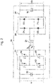
- Fig. 2 shows an example of the configuration of the power converter 20.
- the power converter 20 has an input terminal that is connected to an inverter 21 (second inverter) and a capacitor 22.
- Fig. 2 shows a full-bridge inverter circuit including four elements (M 1 to M 4 ), as the circuit configuration of the inverter 21, which may have other circuit configurations.
- the AC output terminal of the inverter 21 is connected to the primary winding of a transformer 23.
- the secondary winding of the transformer 23 is connected to an AC input terminal of a rectifier circuit 24 (third rectifier circuit).
- Fig. 2 shows a full-bridge rectifier circuit including four diodes (D 1 to D 4 ) as the circuit configuration of the rectifier circuit 24, which may have other circuit configurations.
- the DC output terminal of the rectifier circuit 24 is connected to the output terminal of the power converter 20 via a filter circuit including a choke coil 25 and a capacitor 26.
- the inverter 21 converts the main DC voltage Vi input to the power converter 20 into AC voltage V tr and applies it to the primary winding of the transformer 23.
- the AC current flowing through the primary winding of the transformer 23 is defined as the primary winding current Itr.
- the transformer 23 transforms the voltage applied to the primary winding to generate AC voltage in the secondary winding, while insulating between the input and output of the power converter 20. This AC voltage is converted to DC voltage by the rectifier circuit 24 and is output from the power converter 20 through the filter circuit.
- Fig. 2 shows MOSFETs as the elements M 1 to M 4 , which may be power semiconductor devices or power semiconductors, including other types of devices such as IGBTs.
- the power converter 20 may also include control components such as breakers and relays, protective components such as fuses and surge protectors, and noise filters.
- Fig. 3 shows the operating waveforms of a power converter 20 in a conventional regenerative braking system.
- the power converter 20 converts power with switching operations of elements M 1 to M 4
- Fig. 3 shows operating waveforms for two switching cycles.
- the vertical axis in Fig. 3 represents the drive signals (on/off signals) of the elements M 1 to M 4 , the primary winding voltage Vtr of the transformer 23, the primary winding current Itr of the transformer 23, and the output current I ⁇ of the power converter 20.
- Fig. 3(a) assumes that the main DC voltage V i is the minimum value V 1
- Fig. 3(b) assumes that the main DC voltage V i is the maximum value V 2
- Both Figs. 3(a) and 3(b) assume that the output power P o of the power converter 20 is controlled to the rated value (rated power) P 1
- Fig. 3 assumes phase shift control that is used as the specific control method for the inverter 21 (full bridge inverter circuit).
- the phase shift control enables soft switching of the turn-on of M 1 to M 4 , so that the turn-on loss can be made almost zero. Since the phase shift control is a known technology, the detailed explanations of the operation mode and current path will be omitted, and the following mainly describes the outline of the operation and the effect of fluctuations of the main DC voltage V i .
- the elements M 1 and M 2 on the left leg of Fig. 2 are complementarily controlled on/off with a dead time t d in between.
- the elements M 3 and M 4 on the right leg of Fig. 2 are identical to the elements M 3 and M 4 on the right leg of Fig. 2 .
- the inverter 21 delays the switching of the element M 4 by the shift amount ⁇ as compared with the element M 1 and similarly delays the switching of the element M 3 by the shift amount ⁇ as compared with the element M 2 .
- the inverter 21 changes the shift amount ⁇ to control the output of the power converter 20. If the output of the power converter 20 is kept under the same condition, the shift amount ⁇ increases with the main DC voltage V i .
- the turns ratio of the transformer 23 is desirably designed so that the shift amount ⁇ becomes almost zero.
- the elements M 1 and M 4 and the elements M 2 and M 3 switch at almost the same time.
- the primary winding voltage Vtr of the transformer 23 becomes a rectangular pulse, voltage, and has the amplitude almost equal to the main DC voltage V i .
- the phase shift operation generation of ⁇
- the shift amount ⁇ increases with the main DC voltage V i , so that although the amplitude of the primary winding voltage Vtr increases, the period during which the primary winding voltage Vtr becomes zero also increases.
- the primary winding current I tr is also the current flowing through the inverter 21.
- the amplitude of the primary winding current I tr mainly depends on the output current I ⁇ and the turns ratio of the transformer 23, and is almost independent of the main DC voltage V i .
- Figs. 3(a) and 3(b) show the turn-off currents I off1 and I 0ff2 of the element M 1 , and the turn-off currents I off1 and I off2 also hardly depend on the main DC voltage V i .
- the regenerative braking system of the present embodiment is configured to, when the main DC voltage V i is larger than a predetermined threshold (first threshold), reduce the output power P o of the power converter 20 than when the main DC voltage Vi is equal to or less than the predetermined threshold.
- the controller 40 in Fig. 1 controls various devices of the electric drive system shown in the drawing.
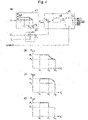
- Fig. 4 is a block diagram showing the part of the system that controls the power converter 20.
- the controller 40 includes an output power table 41, an output power calculation unit 42, and a control calculation unit 43.
- the output power table 41 refers to the table according to the input main DC voltage V i , and outputs a command value P oref of the output power.
- the predetermined threshold is V c (V 1 ⁇ V c ⁇ V 2) .
- the output power command value P oref is set at the rated output power P 1 .
- the output power command value P oref is set smaller than the rated value P 1 .
- Fig. 4(a) shows an example where the output power command value P oref is a linear function of the main DC voltage V i so that the output power command value P oref when the main DC voltage V i is the maximum value V 2 is set to the lower limit P 2 .
- the region where the main DC voltage V i is larger than the threshold V c and the output power command value P oref is smaller than the rated value P 1 , that is, V i >V c and P oref ⁇ P 1 , is defined as an output reduction region.
- Fig. ,4(a) shows the case where the main DC voltage V i and the output power command value P oref have a relationship of a linear function such that the output power command value P oref decreases from the rated value P 1 by a certain ratio with an increase of the main DC voltage V i from the threshold V c .
- the relationship between the main DC voltage V i and the output power command value P oref when the main DC voltage V i is larger than the threshold V c (V i >V c ) is not limited to the linear function relationship shown in Fig. 4(a) .
- the relationship may be such that the output power command value P oref is smaller than the rated value P 1 (P oref ⁇ P 1 ) when the main DC voltage V i is larger than the threshold V c (V i >V c ).
- the control calculation unit 43 generates a control signal for the power converter 20 based on the output power P o and the output power command value P oref .
- Fig. 4(a) shows drive signals for elements M 1 to M 4 as control signals. Assuming the phase shift control described above, a shift amount calculation unit 44 and a drive signal generator 45 are shown as the internal configuration of the control calculation unit 43. In other words, the control calculation unit 43 of the present embodiment has the shift amount calculation unit 44 and the drive signal generator 45.
- the shift amount calculation unit 44 calculates the shift amount ⁇ by a control calculation such as proportional/integral control (PI control).
- PI control proportional/integral control
- the shift amount ⁇ is calculated so that when the output power P o is smaller than the output power command value P oref (P o ⁇ P oref ), the shift amount ⁇ decreases, and when the output power P o is equal to or more than the output power command value P oref (P o >P oref ), the shift amount ⁇ increases. That is, the shift amount calculation unit 44 calculates the shift amount ⁇ so that the output power P o remains constant. For example, as the main DC voltage V i increases due to braking of the electric vehicle, the shift amount ⁇ also increases to keep the output power P o constant.
- the drive signal generator 45 generates drive signals for the elements M 1 to M 4 from the shift amount ⁇ . This embodiment assumes that because the control response of the output power P o by the control calculation unit 43 is sufficiently high, the output power P o equals the output power command value P oref .
- the drive signal generator 45 of the control calculation unit 43 receives an enable signal (Enable in Fig. 4(a) ) to control the operation or stop of the power converter 20.
- This enable signal is a digital signal generated inside the controller 40, and its logical level represents the operation or stop of the power converter 20.
- This configuration generates the drive signal so that the power converter 20 stops during acceleration, i.e., all elements M 1 to M 4 turn off.
- Fig. 5 shows the operating waveforms of the power converter 20 in the present embodiment. The descriptions in common with Fig. 3 will be omitted.
- Fig. 5(a) shows the example where the main DC voltage V i is the minimum value V i smaller than the threshold V c , and the output power P o of the power converter 20 is controlled to the rated value P 1 .
- Fig. 5(b) shows the example where the main DC voltage V i has a value V 2 larger than the threshold V c , and the output power P o is controlled to a lower limit value P 2 that is smaller than the rated value P 1 due to the configuration described in Fig. 4 . Note that since the conditions of the main DC voltage V i and the output power P o are the same in Figs.
- the amplitude of the primary winding current Itr of the transformer 23 and the turn-off currents I off1 and I 0ff2 of the element M 1 depend on the output current I o .
- the output current I ⁇ is smaller than in Fig. 5(a) , so that the amplitude of the primary winding current Itr and the turn-off current I off2 are also smaller (I off1 >I off2 ).
- Comparison between Fig. 3(b) and Fig. 5(b) also shows that the output current I o , Itr amplitude, and turn-off current I off2 are smaller in Fig. 5(b) .
- the control to reduce the output power P o described in Fig. 4 reduces the turn-off loss of the elements under the condition of large main DC voltage V i and so reduces the resulting heat generation. Further, a larger reduction amount of the output power P o , that is, the output current I ⁇ leads to a greater effect of reducing the heat generation of the power converter 20.
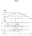
- Fig. 6 is a timing chart showing the power change of the devices when the main DC voltage V i fluctuates. Specifically, the drawing shows the output power P o of the power converter 20, the output power P g of the auxiliary generator 31, and the power consumption P a of the auxiliary device 33.
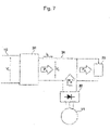
- Fig. 7 shows only the devices related to Fig. 1 through Fig. 6 , with the power defined by arrows. Fig. 7 shows the flow of power when the electric vehicle is braked, showing the case where the power converter 20 can output the power. As shown in Fig. 6 , assume that the power consumption P a of the auxiliary device 33 is constant and is larger than the output power P o . In Fig.
- the output power command value P oref is reduced to be smaller than the rated value P 1 with an increase of the main DC voltage V i according to the output power table 41 in Fig. 4 .
- the output power P o therefore also gradually decreases as shown in Fig. 6 .
- the auxiliary generator 31 gradually increases the auxiliary output power P g to control the auxiliary DC voltage V o to be constant.
- the controller 40 controls the auxiliary generator 31 to increase the auxiliary output power P g of the auxiliary generator 31 by the amount of the decrease in the output power P o of the power converter 20.
- the auxiliary generator 31 increases the power by ⁇ P, so that the power P a supplied to the auxiliary device 33 is kept constant.
- the output power P o is controlled to the lower limit P 2 , which is smaller than the rated value P 1 .
- P g P a -P 2 .
- the powers change in the same manner. The detailed explanation is omitted.
- Embodiment 1 provides the power converter 20 and the regenerative braking system including this to realize energy saving of the electric vehicle.
- This embodiment also copes with the input voltage fluctuations of the power converter 20 to reduce heat generation of the switching elements, especially when the input voltage is large. This is effective for extending the life of the elements and improving the long-term reliability. This also minimizes the cooling system and lowers the cost within the range of the temperature constraints of the elements.
- Embodiment 1 focuses on the turn-off loss as a heat generation factor of the elements. Reduction of the turn-off loss and of the resulting heat generation increases the switching frequency of the elements. This reduces the size of the transformer 23, the choke coil 25, and the capacitor 26 in the power converter 20, and lowers their cost.
- Fig. 8 shows another example of the timing chart, in which power consumption control of the auxiliary device 33 is performed. The features in common with Fig. 6 are omitted.
- the controller 40 is capable of controlling the power consumption P a of the auxiliary device 33.
- the controller 40 decreases the power consumption P a of the auxiliary device 33 by the amount of the decrease in the output power P o of the power converter 20.
- the controller 40 also reduces the power consumption P a by ⁇ P.
- auxiliary generator 31 This allows the auxiliary generator 31 to control the auxiliary DC voltage V o to constant without increasing the auxiliary output power P g .
- the power consumption of the auxiliary device such as an air conditioner, which does not significantly affect the running of the vehicle, may be reduced.
- the supplemental information on the output power table 41 shown in Fig. 4(a) is as follows.
- the output power P o is controlled to the rated value P 1 regardless of the value of the main DC voltage V i , the turn-off loss of the elements and the resulting heat generation increase with the main DC voltage V i . Therefore, as shown in the output power table 41 in Fig. 4(a) , it is effective to, in the output reduction region where the main DC voltage V i is larger than the threshold V c , control the output power P o to be smaller for a larger main DC voltage V i to increase the effect of heat generation reduction.
- the output power table 41 of Fig. 4(a) is configured so that the output power P o is a linear function of the main DC voltage V i in the output reduction region.
- the output power P o may be inversely proportional to the main DC voltage V i in this region.
- Figs. 4(b) to 4(d) show other examples of the relationship between the main DC voltage V i and the output power command value P oref when the main DC voltage V i is larger than the threshold V c (V i >V c ).
- FIG. 4(c) shows the case where the rate of decreasing the output power command value P oref increases in a quadratic manner with the increase of the main DC voltage V i from the threshold V c .
- Fig. 4(d) shows the case where the output power command value P oref changes stepwise from the rated output power P 1 to a smaller value with the increase of the main DC voltage V i from the threshold V c .
- Embodiment 2 of the present invention uses the electric drive system shown in Fig. 1 .
- Embodiment 2 is different from Embodiment 1 in the internal configuration (block diagram) of the controller 40.
- Embodiment 2 controls the output power P o of the power converter 20 using the temperature T o of the power converter 20, which is detected by the temperature detector 27.
- Fig. 9 is a block diagram showing the part of the controller 40 in Embodiment 2 that controls the power converter 20.
- the output power calculation unit 42 and the control calculation unit 43 are the same as those in Fig. 4 (Embodiment 1), description thereof will be omitted.
- the controller 40 in Embodiment 2 includes an output power table 46.
- the output power table 46 creates an output power command value P oref of the power converter 20 based on the main DC voltage V i .
- the output power table 41 uses the threshold V c (threshold related to the main DC voltage V i ) and the lower limit value P 2 (output power command value P oref under the condition where the main DC voltage V i is the maximum value V 2 ) as two internal parameters.
- Embodiment 2 uses a threshold V c ' (first threshold) instead of the threshold V c , and the lower limit value P 2 ' instead of the lower limit value P 2 . These parameters change with the temperature T o of the power converter 20 as described later.
- the controller 40 of Embodiment 2 has a threshold table 47 that creates a threshold V c ' based on the temperature T o of the power converter 20, and an output lower limit table 48 that creates a lower limit value P 2 ' based on the temperature T o .
- the threshold table 47 decreases the threshold V c ' with an increase of the temperature T o .
- the output lower limit table 48 decreases the lower limit P 2 ' with an increase of the temperature T o .
- the output power command value P oref decreases with an increase of the temperature T o under the same main DC voltage V i condition and when the main DC voltage V i is larger than the threshold V c ' (V i >V c '), the output power command value P oref decreases with an increase of the temperature T o .
- This embodiment increases the effect of reducing heat generation of the elements described in Embodiment 1 for a higher temperature T o .
- the reduction of the output power P o can be reduced to enhance the energy saving effect of the regenerative braking system.
- the output power P o is set as a linear function of the main DC voltage V i in the output reduction region, and its slope is made constant regardless of the temperature T o .
- the output power command value P oref under the condition where the main DC voltage V i is the maximum value V 2 decreases with an increase of the temperature T o .
- the output power P o is inversely proportional to the main DC voltage V i in the output reduction region.
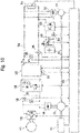
- Fig. 10 the following describes a hardware configuration of the electric drive system in Embodiment 3.
- the features in common with Fig. 1 (Embodiment 1 or 2) are omitted.
- the electric drive system of Fig. 10 has a storage device 51 and its charger/discharger 52 that are connected to the auxiliary DC line 34.
- This system has a voltage detector 53 that detects the voltage V b (third DC voltage) of the storage device 51 and a current detector 54 that detects the charge/discharge current I b of the storage device 51.
- the storage device 51 is connected to the input of the charger/discharger 52 via the current detector 54.
- the output of the charger/discharger 52 is connected to the auxiliary DC line 34.
- the storage device 51 and its charger/discharger 52 make up the electrical load of the electric drive system.
- Examples of the storage device 51 include batteries such as a nickel hydrogen battery and a lithium ion battery, and capacitors such as an electric double layer capacitor and a lithium ion capacitor.
- the charger/discharger 52 is a DC/DC converter enabling bidirectional operation, and charges the storage device 51 by transmitting power from the output side to the input side, and discharges power of the storage device 51 by transmitting the power from the input side to the output side.
- a bidirectional chopper circuit can be the circuit scheme for the charger/discharger 52, which may be other schemes.
- Fig. 10 assumes an IGBT as the switching element of the charger/discharger 52, and indicates it with the circuit symbol for IGBT.
- Other types of elements such as a MOSFET may be used.
- the positive/negative polarity of the charge/discharge current I b of the storage device 51 is defined so that the charge/discharge current I b becomes positive when the storage device 51 discharges.
- the charge/discharge power of the storage device 51, P b V b I b , is also positive when the storage device 51 discharges.
- the electric drive system in Fig. 10 includes a controller 60.
- the controller 60 is different from the controller 40 in Fig. 1 .(Embodiment 1 or 2) in that it acquires information on the voltage V b of the storage device 51 from the voltage detector 53 and acquires information on the charge/discharge current I b from the current detector 54.
- the controller 60 outputs a control signal to the charger/discharger 52.
- the control signal from the controller 60 to the charger/discharger 52 is indicated with a single arrow.
- the charger/discharger 52 may include a plurality of elements. In that case, the signal also may be a plurality of control signals. In this way, the embodiment having the storage device 51 allows a part of the output power P o of the power converter 20 to be stored in the storage device 51 and be used during acceleration of the vehicle, for example.
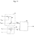
- Fig. 11 is a block diagram showing the part of the controller 60 that controls the charger/discharger 52.
- the controller 60 includes a charge/discharge command correction unit 61, a charge/discharge power calculation unit 62, and a control calculation unit 63.
- the charge/discharge command correction unit 61 receives inputs from the power converter 20 that are the output power command value P oref and the charge/discharge command value P bref0 before correction.
- the output power command value P oref is created in the same way as in Embodiment 1 or 2. For example, it is generated with the output power table shown in Fig. 4(a) or Fig. 9 .
- the charge/discharge command value P bref0 before correction is created by a higher-order system than the block diagram of Fig. 11 , and is input to the charge/discharge command correction unit 61.
- the charge/discharge command correction unit 61 calculates a reduction amount ⁇ P of the output power P o from the output power command value P oref and its rated value P 1 .
- the charge/discharge command correction unit 61 adds the charge/discharge command value P bref0 before correction and the reduction ⁇ P to calculate a corrected charge/discharge command value P bref . If it is the discharge state before correction, i.e., P bref0 >0, the discharge power will be even larger due to the addition described above.
- the charge/discharge command correction unit 61 corrects the charge/discharge command value of the charger/discharger 52 so as to suppress fluctuations in the power supplied to the auxiliary DC line 34 when reducing the output power of the power converter 20.
- the control calculation unit 63 generates a control signal for the charger/discharger 52 based on the charge/discharge power P b and the corrected charge/discharge command value P bref0.
- the present embodiment assumes that the control response of the charge/discharge power P b by the control calculation unit 63 is sufficiently high, and the charge/discharge power P b equals the corrected charge/discharge command value P bref0 .
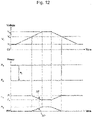
- Fig. 12 is a timing chart showing the power change of the devices when the main DC voltage V i fluctuates.
- Fig. 12 shows charge/discharge power P b of the storage device 51 in addition to the output power P o of the power converter 20, the auxiliary output power P g of the auxiliary generator 31, and the power consumption P a of the auxiliary device 33.
- Fig. 13 shows only the devices related to Fig. 10 through Fig. 12 , with the power defined by arrows.
- Fig. 13 shows the flow of power when the electric vehicle is braked, showing the case where the power converter 20 can output the power.
- the power consumption P a of the auxiliary device 33 is constant and is larger than the output power P o .
- the charge/discharge command value P bref0 before correction shown in Fig. 11 is zero and that the charger/discharger 52 neither charges nor discharges when the output power of the power converter 20 is not reduced.
- the losses in the charger/discharger 52 are ignored, and the power that the charger/discharger 52 outputs to the auxiliary DC line 34 is the charge/discharge power P b .
- the output power command value P oref is reduced according to the output power table 41 in Fig. 4(a) , so that the output power P o gradually decreases as shown in Fig. 12 .
- Embodiment 1 shows the configuration in which the auxiliary generator 31 increases its output to compensate for the reduced output of the power converter 20, and supplies a constant amount of power to the auxiliary device 33.
- the control of the auxiliary generator 31 cannot follow, and the auxiliary DC voltage V o temporarily decreases.
- a method of connecting a large-capacity smoothing capacitor to the auxiliary DC line 34 can be used.
- This method has the problem that the system becomes larger and more expensive due to the smoothing capacitor.
- Embodiment 3 is configured so that, instead of the auxiliary generator 31, the storage device 51 and the charger/discharger 52 compensate for the reduced output of the power converter 20. Since the power density of the storage device 51 is improving year by year, the storage device 51 controls the output faster than the auxiliary generator 31. This makes it possible to control the auxiliary DC voltage V o to a constant level even when the main DC voltage V i changes suddenly.
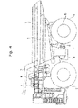
- Fig. 14 describes a basic configuration of a dump track that is common to all the embodiments.
- the dump truck has a body 5 for loading earth and sand, for example, on a frame 1, and the body 5 and the frame 1 are connected by a hoist cylinder 6.
- a hoist cylinder 6 To the frame 1, front wheels 2, rear wheels 3, a fuel tank 9, and the like are attached via mechanical parts (not shown).
- the rotating shaft of the rear wheels 3 contains a driving motor 10 for driving the rear wheels 3 and a decelerator for adjusting the rotation speed of the rear wheels 3.
- the frame 1 also has a deck attached so as to allow an operator to walk thereon.
- the deck includes a cab 4 for operators to board and operate the dump truck, a control cabinet 8 containing various electric power devices, and a plurality of grid boxes 7 for dissipating excess energy as heat.
- the resistors of the power consumption device 15 shown in Figs. 1 and 10 are housed in the grid box 7.
- the part hidden by the front wheels 2 in Fig. 14 houses the engine, the main generator that functions mainly as a power source for driving motor, the auxiliary generator that functions mainly as a power source for auxiliary devices, and a main pump (not shown) mainly as a hydraulic source for hydraulic equipment.
- an accelerator pedal, a brake pedal, a hoist pedal, and a steering wheel are installed in the cab 4.
- the operator can control the acceleration force and braking force of the dump truck with the amount of depression of the accelerator pedal and the amount of depression of the brake pedal in the cab 4.
- the operator also performs the steering operation with hydraulic drive by rotating the steering wheel left and right, and performs the dump operation with hydraulic drive by depressing the hoist pedal.
- the system for the steering operation and the dump operation of the present invention are the same as in the conventional techniques, and they will not be described in detail.
Landscapes
- Engineering & Computer Science (AREA)
- Power Engineering (AREA)
- Transportation (AREA)
- Mechanical Engineering (AREA)
- Combustion & Propulsion (AREA)
- Chemical & Material Sciences (AREA)
- Life Sciences & Earth Sciences (AREA)
- Sustainable Development (AREA)
- Sustainable Energy (AREA)
- Automation & Control Theory (AREA)
- Electric Propulsion And Braking For Vehicles (AREA)
- Dc-Dc Converters (AREA)
- Charge And Discharge Circuits For Batteries Or The Like (AREA)
- Hybrid Electric Vehicles (AREA)
- Inverter Devices (AREA)
Applications Claiming Priority (2)
| Application Number | Priority Date | Filing Date | Title |
|---|---|---|---|
| JP2019137191A JP7129956B2 (ja) | 2019-07-25 | 2019-07-25 | 電動車両 |
| PCT/JP2020/026526 WO2021014961A1 (ja) | 2019-07-25 | 2020-07-07 | 電動車両 |
Publications (2)
| Publication Number | Publication Date |
|---|---|
| EP4005848A1 true EP4005848A1 (de) | 2022-06-01 |
| EP4005848A4 EP4005848A4 (de) | 2023-09-13 |
Family
ID=74193852
Family Applications (1)
| Application Number | Title | Priority Date | Filing Date |
|---|---|---|---|
| EP20843073.6A Pending EP4005848A4 (de) | 2019-07-25 | 2020-07-07 | Elektrofahrzeug |
Country Status (5)
| Country | Link |
|---|---|
| US (1) | US12187130B2 (de) |
| EP (1) | EP4005848A4 (de) |
| JP (1) | JP7129956B2 (de) |
| CN (1) | CN113840753B (de) |
| WO (1) | WO2021014961A1 (de) |
Families Citing this family (7)
| Publication number | Priority date | Publication date | Assignee | Title |
|---|---|---|---|---|
| JP7130024B2 (ja) * | 2020-11-12 | 2022-09-02 | 三菱電機株式会社 | 電力変換装置 |
| JP2024053572A (ja) * | 2022-10-04 | 2024-04-16 | 日立建機株式会社 | 電動作業車両 |
| CN115946547A (zh) * | 2022-12-06 | 2023-04-11 | 太原重工股份有限公司 | 一种基于碳基电容电池的混合动力系统及控制方法 |
| CN116299021B (zh) * | 2022-12-30 | 2026-04-14 | 西门子爱克斯射线真空技术(无锡)有限公司 | 一种电能发生器及其自动检测电路 |
| CN116653600A (zh) * | 2023-05-16 | 2023-08-29 | 名商科技有限公司 | 一种精准控制功率的车载电源管理方法及系统 |
| US20260097638A1 (en) * | 2024-10-09 | 2026-04-09 | Caterpillar Inc. | Hybrid drive system for work machine |
| CN119850125B (zh) * | 2024-12-23 | 2025-10-24 | 中国电力科学研究院有限公司 | 一种数据全生命周期治理的方法及系统 |
Family Cites Families (11)
| Publication number | Priority date | Publication date | Assignee | Title |
|---|---|---|---|---|
| JP2600638Y2 (ja) * | 1993-03-11 | 1999-10-18 | 株式会社小糸製作所 | 車輌用放電灯の点灯回路 |
| JP2002330554A (ja) | 2001-04-27 | 2002-11-15 | Kobelco Contstruction Machinery Ltd | ハイブリッド車両の電力制御装置および当該電力制御装置を備えたハイブリッド建設機械 |
| JP2010074913A (ja) | 2008-09-17 | 2010-04-02 | Toyota Motor Corp | 電源システムおよびそれを搭載した車両 |
| JP5315915B2 (ja) | 2008-10-17 | 2013-10-16 | トヨタ自動車株式会社 | 電源システムおよびその制御方法 |
| RU2551690C2 (ru) | 2009-04-27 | 2015-05-27 | Вольво Ластвагнар Аб | Система зарядки аккумуляторных батарей для гибридного электрического транспортного средства |
| JP2012244748A (ja) * | 2011-05-19 | 2012-12-10 | Toyota Motor Corp | 電力変換制御装置 |
| WO2016084801A1 (ja) * | 2014-11-25 | 2016-06-02 | ヤマハ発動機株式会社 | 駆動システム、及びビークル |
| JP6468203B2 (ja) * | 2016-01-13 | 2019-02-13 | トヨタ自動車株式会社 | 電源システム |
| JP6681002B2 (ja) | 2016-03-30 | 2020-04-15 | 三菱自動車工業株式会社 | ハイブリッド車両の電力制御装置 |
| EP3511192B1 (de) * | 2016-09-08 | 2022-05-11 | Hitachi Construction Machinery Co., Ltd. | Regenerative bremsvorrichtung und muldenkipper |
| JP6909694B2 (ja) | 2017-09-29 | 2021-07-28 | 日立建機株式会社 | 作業車両の電力回生システム |
-
2019
- 2019-07-25 JP JP2019137191A patent/JP7129956B2/ja active Active
-
2020
- 2020-07-07 US US17/625,795 patent/US12187130B2/en active Active
- 2020-07-07 WO PCT/JP2020/026526 patent/WO2021014961A1/ja not_active Ceased
- 2020-07-07 EP EP20843073.6A patent/EP4005848A4/de active Pending
- 2020-07-07 CN CN202080037250.6A patent/CN113840753B/zh active Active
Also Published As
| Publication number | Publication date |
|---|---|
| CN113840753A (zh) | 2021-12-24 |
| CN113840753B (zh) | 2024-10-11 |
| JP7129956B2 (ja) | 2022-09-02 |
| JP2021022988A (ja) | 2021-02-18 |
| WO2021014961A1 (ja) | 2021-01-28 |
| US12187130B2 (en) | 2025-01-07 |
| US20220258593A1 (en) | 2022-08-18 |
| EP4005848A4 (de) | 2023-09-13 |
Similar Documents
| Publication | Publication Date | Title |
|---|---|---|
| US12187130B2 (en) | Electric vehicle | |
| JP5972785B2 (ja) | 電気車制御装置 | |
| JP6909694B2 (ja) | 作業車両の電力回生システム | |
| US10236803B2 (en) | Hybrid-vehicle variable-voltage traction motor drive | |
| US7960855B2 (en) | System and method for providing power control of an energy storage system | |
| KR101017089B1 (ko) | 모터구동장치 및 그 제어방법 | |
| US20100045102A1 (en) | Bidirectional buck boost dc-dc converter, railway coach drive control system, and railway feeder system | |
| US20030117113A1 (en) | Hybrid vehicle and control method therefor | |
| US11834033B2 (en) | Regenerative braking system and electrically-driven work vehicle using regenerative braking system | |
| KR20040009370A (ko) | 연료 전지 하이브리드 전기자동차의 연료 전지 출력 파워제어방법 | |
| US12160194B2 (en) | Regenerative braking system, and electrically driven work vehicle using the same | |
| KR20170086298A (ko) | 전기차량의 충전제어 시스템 | |
| JP4238190B2 (ja) | 電力貯蔵式回生電力吸収装置およびその制御方法 | |
| US12466447B1 (en) | Battery powered locomotive | |
| JP2015104195A (ja) | 電気自動車の電源システム | |
| JP5385728B2 (ja) | 制御方法及び制御装置 | |
| JP2024506944A (ja) | Dc電源デバイス及びこれを組み込んだ鉄道用変電所 | |
| US12132425B2 (en) | Motor drive system and torque distribution method thereof | |
| JP2024053572A (ja) | 電動作業車両 | |
| JP2024052227A (ja) | 電動車両 | |
| Jha et al. | A Multi-Functional Power Electronics Converter Configuration for Electric Vehicles | |
| KR102457211B1 (ko) | 전력 공급 장치 및 방법 | |
| KR20240077116A (ko) | 연료 전지 차 및 이의 제어 방법 | |
| JP2023087713A (ja) | 電動車両 | |
| KR20240014854A (ko) | 전동화 차량 |
Legal Events
| Date | Code | Title | Description |
|---|---|---|---|
| STAA | Information on the status of an ep patent application or granted ep patent |
Free format text: STATUS: THE INTERNATIONAL PUBLICATION HAS BEEN MADE |
|
| PUAI | Public reference made under article 153(3) epc to a published international application that has entered the european phase |
Free format text: ORIGINAL CODE: 0009012 |
|
| STAA | Information on the status of an ep patent application or granted ep patent |
Free format text: STATUS: REQUEST FOR EXAMINATION WAS MADE |
|
| 17P | Request for examination filed |
Effective date: 20220225 |
|
| AK | Designated contracting states |
Kind code of ref document: A1 Designated state(s): AL AT BE BG CH CY CZ DE DK EE ES FI FR GB GR HR HU IE IS IT LI LT LU LV MC MK MT NL NO PL PT RO RS SE SI SK SM TR |
|
| DAV | Request for validation of the european patent (deleted) | ||
| DAX | Request for extension of the european patent (deleted) | ||
| A4 | Supplementary search report drawn up and despatched |
Effective date: 20230814 |