EP4005863B1 - Stromversorgungssystem und verfahren zur steuerung eines solchen stromversorgungssystems - Google Patents
Stromversorgungssystem und verfahren zur steuerung eines solchen stromversorgungssystems Download PDFInfo
- Publication number
- EP4005863B1 EP4005863B1 EP21211022.5A EP21211022A EP4005863B1 EP 4005863 B1 EP4005863 B1 EP 4005863B1 EP 21211022 A EP21211022 A EP 21211022A EP 4005863 B1 EP4005863 B1 EP 4005863B1
- Authority
- EP
- European Patent Office
- Prior art keywords
- power
- battery
- fuel cell
- value
- electrical power
- Prior art date
- Legal status (The legal status is an assumption and is not a legal conclusion. Google has not performed a legal analysis and makes no representation as to the accuracy of the status listed.)
- Active
Links
Images

Classifications
-
- B—PERFORMING OPERATIONS; TRANSPORTING
- B60—VEHICLES IN GENERAL
- B60L—PROPULSION OF ELECTRICALLY-PROPELLED VEHICLES; SUPPLYING ELECTRIC POWER FOR AUXILIARY EQUIPMENT OF ELECTRICALLY-PROPELLED VEHICLES; ELECTRODYNAMIC BRAKE SYSTEMS FOR VEHICLES IN GENERAL; MAGNETIC SUSPENSION OR LEVITATION FOR VEHICLES; MONITORING OPERATING VARIABLES OF ELECTRICALLY-PROPELLED VEHICLES; ELECTRIC SAFETY DEVICES FOR ELECTRICALLY-PROPELLED VEHICLES
- B60L50/00—Electric propulsion with power supplied within the vehicle
- B60L50/50—Electric propulsion with power supplied within the vehicle using propulsion power supplied by batteries or fuel cells
- B60L50/70—Electric propulsion with power supplied within the vehicle using propulsion power supplied by batteries or fuel cells using power supplied by fuel cells
- B60L50/71—Arrangement of fuel cells within vehicles specially adapted for electric vehicles
-
- B—PERFORMING OPERATIONS; TRANSPORTING
- B60—VEHICLES IN GENERAL
- B60L—PROPULSION OF ELECTRICALLY-PROPELLED VEHICLES; SUPPLYING ELECTRIC POWER FOR AUXILIARY EQUIPMENT OF ELECTRICALLY-PROPELLED VEHICLES; ELECTRODYNAMIC BRAKE SYSTEMS FOR VEHICLES IN GENERAL; MAGNETIC SUSPENSION OR LEVITATION FOR VEHICLES; MONITORING OPERATING VARIABLES OF ELECTRICALLY-PROPELLED VEHICLES; ELECTRIC SAFETY DEVICES FOR ELECTRICALLY-PROPELLED VEHICLES
- B60L58/00—Methods or circuit arrangements for monitoring or controlling batteries or fuel cells, specially adapted for electric vehicles
- B60L58/40—Methods or circuit arrangements for monitoring or controlling batteries or fuel cells, specially adapted for electric vehicles for controlling a combination of batteries and fuel cells
-
- B—PERFORMING OPERATIONS; TRANSPORTING
- B60—VEHICLES IN GENERAL
- B60K—ARRANGEMENT OR MOUNTING OF PROPULSION UNITS OR OF TRANSMISSIONS IN VEHICLES; ARRANGEMENT OR MOUNTING OF PLURAL DIVERSE PRIME-MOVERS IN VEHICLES; AUXILIARY DRIVES FOR VEHICLES; INSTRUMENTATION OR DASHBOARDS FOR VEHICLES; ARRANGEMENTS IN CONNECTION WITH COOLING, AIR INTAKE, GAS EXHAUST OR FUEL SUPPLY OF PROPULSION UNITS IN VEHICLES
- B60K1/00—Arrangement or mounting of electrical propulsion units
- B60K1/04—Arrangement or mounting of electrical propulsion units of the electric storage means for propulsion
-
- B—PERFORMING OPERATIONS; TRANSPORTING
- B60—VEHICLES IN GENERAL
- B60L—PROPULSION OF ELECTRICALLY-PROPELLED VEHICLES; SUPPLYING ELECTRIC POWER FOR AUXILIARY EQUIPMENT OF ELECTRICALLY-PROPELLED VEHICLES; ELECTRODYNAMIC BRAKE SYSTEMS FOR VEHICLES IN GENERAL; MAGNETIC SUSPENSION OR LEVITATION FOR VEHICLES; MONITORING OPERATING VARIABLES OF ELECTRICALLY-PROPELLED VEHICLES; ELECTRIC SAFETY DEVICES FOR ELECTRICALLY-PROPELLED VEHICLES
- B60L1/00—Supplying electric power to auxiliary equipment of vehicles
-
- B—PERFORMING OPERATIONS; TRANSPORTING
- B60—VEHICLES IN GENERAL
- B60L—PROPULSION OF ELECTRICALLY-PROPELLED VEHICLES; SUPPLYING ELECTRIC POWER FOR AUXILIARY EQUIPMENT OF ELECTRICALLY-PROPELLED VEHICLES; ELECTRODYNAMIC BRAKE SYSTEMS FOR VEHICLES IN GENERAL; MAGNETIC SUSPENSION OR LEVITATION FOR VEHICLES; MONITORING OPERATING VARIABLES OF ELECTRICALLY-PROPELLED VEHICLES; ELECTRIC SAFETY DEVICES FOR ELECTRICALLY-PROPELLED VEHICLES
- B60L1/00—Supplying electric power to auxiliary equipment of vehicles
- B60L1/003—Supplying electric power to auxiliary equipment of vehicles to auxiliary motors, e.g. for pumps, compressors
-
- B—PERFORMING OPERATIONS; TRANSPORTING
- B60—VEHICLES IN GENERAL
- B60L—PROPULSION OF ELECTRICALLY-PROPELLED VEHICLES; SUPPLYING ELECTRIC POWER FOR AUXILIARY EQUIPMENT OF ELECTRICALLY-PROPELLED VEHICLES; ELECTRODYNAMIC BRAKE SYSTEMS FOR VEHICLES IN GENERAL; MAGNETIC SUSPENSION OR LEVITATION FOR VEHICLES; MONITORING OPERATING VARIABLES OF ELECTRICALLY-PROPELLED VEHICLES; ELECTRIC SAFETY DEVICES FOR ELECTRICALLY-PROPELLED VEHICLES
- B60L15/00—Methods, circuits, or devices for controlling the traction-motor speed of electrically-propelled vehicles
- B60L15/20—Methods, circuits, or devices for controlling the traction-motor speed of electrically-propelled vehicles for control of the vehicle or its driving motor to achieve a desired performance, e.g. speed, torque, programmed variation of speed
-
- B—PERFORMING OPERATIONS; TRANSPORTING
- B60—VEHICLES IN GENERAL
- B60L—PROPULSION OF ELECTRICALLY-PROPELLED VEHICLES; SUPPLYING ELECTRIC POWER FOR AUXILIARY EQUIPMENT OF ELECTRICALLY-PROPELLED VEHICLES; ELECTRODYNAMIC BRAKE SYSTEMS FOR VEHICLES IN GENERAL; MAGNETIC SUSPENSION OR LEVITATION FOR VEHICLES; MONITORING OPERATING VARIABLES OF ELECTRICALLY-PROPELLED VEHICLES; ELECTRIC SAFETY DEVICES FOR ELECTRICALLY-PROPELLED VEHICLES
- B60L58/00—Methods or circuit arrangements for monitoring or controlling batteries or fuel cells, specially adapted for electric vehicles
- B60L58/10—Methods or circuit arrangements for monitoring or controlling batteries or fuel cells, specially adapted for electric vehicles for monitoring or controlling batteries
- B60L58/12—Methods or circuit arrangements for monitoring or controlling batteries or fuel cells, specially adapted for electric vehicles for monitoring or controlling batteries responding to state of charge [SoC]
- B60L58/13—Maintaining the SoC within a determined range
-
- B—PERFORMING OPERATIONS; TRANSPORTING
- B60—VEHICLES IN GENERAL
- B60W—CONJOINT CONTROL OF VEHICLE SUB-UNITS OF DIFFERENT TYPE OR DIFFERENT FUNCTION; CONTROL SYSTEMS SPECIALLY ADAPTED FOR HYBRID VEHICLES; ROAD VEHICLE DRIVE CONTROL SYSTEMS FOR PURPOSES NOT RELATED TO THE CONTROL OF A PARTICULAR SUB-UNIT
- B60W10/00—Conjoint control of vehicle sub-units of different type or different function
- B60W10/24—Conjoint control of vehicle sub-units of different type or different function including control of energy storage means
-
- B—PERFORMING OPERATIONS; TRANSPORTING
- B60—VEHICLES IN GENERAL
- B60W—CONJOINT CONTROL OF VEHICLE SUB-UNITS OF DIFFERENT TYPE OR DIFFERENT FUNCTION; CONTROL SYSTEMS SPECIALLY ADAPTED FOR HYBRID VEHICLES; ROAD VEHICLE DRIVE CONTROL SYSTEMS FOR PURPOSES NOT RELATED TO THE CONTROL OF A PARTICULAR SUB-UNIT
- B60W10/00—Conjoint control of vehicle sub-units of different type or different function
- B60W10/24—Conjoint control of vehicle sub-units of different type or different function including control of energy storage means
- B60W10/26—Conjoint control of vehicle sub-units of different type or different function including control of energy storage means for electrical energy, e.g. batteries or capacitors
-
- H—ELECTRICITY
- H01—ELECTRIC ELEMENTS
- H01M—PROCESSES OR MEANS, e.g. BATTERIES, FOR THE DIRECT CONVERSION OF CHEMICAL ENERGY INTO ELECTRICAL ENERGY
- H01M10/00—Secondary cells; Manufacture thereof
- H01M10/42—Methods or arrangements for servicing or maintenance of secondary cells or secondary half-cells
- H01M10/425—Structural combination with electronic components, e.g. electronic circuits integrated to the outside of the casing
-
- H—ELECTRICITY
- H01—ELECTRIC ELEMENTS
- H01M—PROCESSES OR MEANS, e.g. BATTERIES, FOR THE DIRECT CONVERSION OF CHEMICAL ENERGY INTO ELECTRICAL ENERGY
- H01M10/00—Secondary cells; Manufacture thereof
- H01M10/42—Methods or arrangements for servicing or maintenance of secondary cells or secondary half-cells
- H01M10/44—Methods for charging or discharging
-
- H—ELECTRICITY
- H01—ELECTRIC ELEMENTS
- H01M—PROCESSES OR MEANS, e.g. BATTERIES, FOR THE DIRECT CONVERSION OF CHEMICAL ENERGY INTO ELECTRICAL ENERGY
- H01M10/00—Secondary cells; Manufacture thereof
- H01M10/42—Methods or arrangements for servicing or maintenance of secondary cells or secondary half-cells
- H01M10/48—Accumulators combined with arrangements for measuring, testing or indicating the condition of cells, e.g. the level or density of the electrolyte
-
- H—ELECTRICITY
- H01—ELECTRIC ELEMENTS
- H01M—PROCESSES OR MEANS, e.g. BATTERIES, FOR THE DIRECT CONVERSION OF CHEMICAL ENERGY INTO ELECTRICAL ENERGY
- H01M16/00—Structural combinations of different types of electrochemical generators
- H01M16/003—Structural combinations of different types of electrochemical generators of fuel cells with other electrochemical devices, e.g. capacitors, electrolysers
- H01M16/006—Structural combinations of different types of electrochemical generators of fuel cells with other electrochemical devices, e.g. capacitors, electrolysers of fuel cells with rechargeable batteries
-
- H—ELECTRICITY
- H01—ELECTRIC ELEMENTS
- H01M—PROCESSES OR MEANS, e.g. BATTERIES, FOR THE DIRECT CONVERSION OF CHEMICAL ENERGY INTO ELECTRICAL ENERGY
- H01M8/00—Fuel cells; Manufacture thereof
- H01M8/04—Auxiliary arrangements, e.g. for control of pressure or for circulation of fluids
- H01M8/04298—Processes for controlling fuel cells or fuel cell systems
- H01M8/04313—Processes for controlling fuel cells or fuel cell systems characterised by the detection or assessment of variables; characterised by the detection or assessment of failure or abnormal function
- H01M8/04537—Electric variables
- H01M8/04604—Power, energy, capacity or load
-
- H—ELECTRICITY
- H01—ELECTRIC ELEMENTS
- H01M—PROCESSES OR MEANS, e.g. BATTERIES, FOR THE DIRECT CONVERSION OF CHEMICAL ENERGY INTO ELECTRICAL ENERGY
- H01M8/00—Fuel cells; Manufacture thereof
- H01M8/04—Auxiliary arrangements, e.g. for control of pressure or for circulation of fluids
- H01M8/04298—Processes for controlling fuel cells or fuel cell systems
- H01M8/04694—Processes for controlling fuel cells or fuel cell systems characterised by variables to be controlled
- H01M8/04858—Electric variables
- H01M8/04925—Power, energy, capacity or load
-
- H—ELECTRICITY
- H01—ELECTRIC ELEMENTS
- H01M—PROCESSES OR MEANS, e.g. BATTERIES, FOR THE DIRECT CONVERSION OF CHEMICAL ENERGY INTO ELECTRICAL ENERGY
- H01M8/00—Fuel cells; Manufacture thereof
- H01M8/04—Auxiliary arrangements, e.g. for control of pressure or for circulation of fluids
- H01M8/04298—Processes for controlling fuel cells or fuel cell systems
- H01M8/04992—Processes for controlling fuel cells or fuel cell systems characterised by the implementation of mathematical or computational algorithms, e.g. feedback control loops, fuzzy logic, neural networks or artificial intelligence
-
- B—PERFORMING OPERATIONS; TRANSPORTING
- B60—VEHICLES IN GENERAL
- B60L—PROPULSION OF ELECTRICALLY-PROPELLED VEHICLES; SUPPLYING ELECTRIC POWER FOR AUXILIARY EQUIPMENT OF ELECTRICALLY-PROPELLED VEHICLES; ELECTRODYNAMIC BRAKE SYSTEMS FOR VEHICLES IN GENERAL; MAGNETIC SUSPENSION OR LEVITATION FOR VEHICLES; MONITORING OPERATING VARIABLES OF ELECTRICALLY-PROPELLED VEHICLES; ELECTRIC SAFETY DEVICES FOR ELECTRICALLY-PROPELLED VEHICLES
- B60L2200/00—Type of vehicles
- B60L2200/26—Rail vehicles
-
- H—ELECTRICITY
- H01—ELECTRIC ELEMENTS
- H01M—PROCESSES OR MEANS, e.g. BATTERIES, FOR THE DIRECT CONVERSION OF CHEMICAL ENERGY INTO ELECTRICAL ENERGY
- H01M2220/00—Batteries for particular applications
- H01M2220/20—Batteries in motive systems, e.g. vehicle, ship, plane
-
- H—ELECTRICITY
- H01—ELECTRIC ELEMENTS
- H01M—PROCESSES OR MEANS, e.g. BATTERIES, FOR THE DIRECT CONVERSION OF CHEMICAL ENERGY INTO ELECTRICAL ENERGY
- H01M2250/00—Fuel cells for particular applications; Specific features of fuel cell system
- H01M2250/20—Fuel cells in motive systems, e.g. vehicle, ship, plane
-
- Y—GENERAL TAGGING OF NEW TECHNOLOGICAL DEVELOPMENTS; GENERAL TAGGING OF CROSS-SECTIONAL TECHNOLOGIES SPANNING OVER SEVERAL SECTIONS OF THE IPC; TECHNICAL SUBJECTS COVERED BY FORMER USPC CROSS-REFERENCE ART COLLECTIONS [XRACs] AND DIGESTS
- Y02—TECHNOLOGIES OR APPLICATIONS FOR MITIGATION OR ADAPTATION AGAINST CLIMATE CHANGE
- Y02E—REDUCTION OF GREENHOUSE GAS [GHG] EMISSIONS, RELATED TO ENERGY GENERATION, TRANSMISSION OR DISTRIBUTION
- Y02E60/00—Enabling technologies; Technologies with a potential or indirect contribution to GHG emissions mitigation
- Y02E60/10—Energy storage using batteries
-
- Y—GENERAL TAGGING OF NEW TECHNOLOGICAL DEVELOPMENTS; GENERAL TAGGING OF CROSS-SECTIONAL TECHNOLOGIES SPANNING OVER SEVERAL SECTIONS OF THE IPC; TECHNICAL SUBJECTS COVERED BY FORMER USPC CROSS-REFERENCE ART COLLECTIONS [XRACs] AND DIGESTS
- Y02—TECHNOLOGIES OR APPLICATIONS FOR MITIGATION OR ADAPTATION AGAINST CLIMATE CHANGE
- Y02T—CLIMATE CHANGE MITIGATION TECHNOLOGIES RELATED TO TRANSPORTATION
- Y02T10/00—Road transport of goods or passengers
- Y02T10/60—Other road transportation technologies with climate change mitigation effect
- Y02T10/70—Energy storage systems for electromobility, e.g. batteries
-
- Y—GENERAL TAGGING OF NEW TECHNOLOGICAL DEVELOPMENTS; GENERAL TAGGING OF CROSS-SECTIONAL TECHNOLOGIES SPANNING OVER SEVERAL SECTIONS OF THE IPC; TECHNICAL SUBJECTS COVERED BY FORMER USPC CROSS-REFERENCE ART COLLECTIONS [XRACs] AND DIGESTS
- Y02—TECHNOLOGIES OR APPLICATIONS FOR MITIGATION OR ADAPTATION AGAINST CLIMATE CHANGE
- Y02T—CLIMATE CHANGE MITIGATION TECHNOLOGIES RELATED TO TRANSPORTATION
- Y02T90/00—Enabling technologies or technologies with a potential or indirect contribution to GHG emissions mitigation
- Y02T90/40—Application of hydrogen technology to transportation, e.g. using fuel cells
Definitions
- the present invention relates to electrical power systems and methods for controlling such electrical power systems.
- the invention is particularly applicable to electrical power supply systems used in electric vehicles.
- Electric vehicles and more particularly electrically powered rail vehicles, generally include an electricity storage system comprising, for example, one or more electrochemical accumulator batteries.
- the vehicle's powertrain can be powered when the vehicle is not supplied with electricity from an external source, for example when the vehicle is traveling in an area without a catenary or power rail.
- the hydrogen required for the fuel cell to operate is stored in a specific tank on board the vehicle.
- the hydrogen storage techniques that can be used to date require the use of heavy and bulky tanks, which are also particularly expensive. For example, storing one kilogram of hydrogen requires a 25-kilogram tank.
- traction equipment In many applications, for example in rail or passenger transport, traction equipment must be kept to a reasonable size and weight, so that it is not possible to increase the amount of hydrogen stored on board the vehicle at will.
- the fuel cell has sufficient energy autonomy to contribute to the power supply of the vehicle.
- the document US 2013/065089 A1 discloses a system for managing a fuel cell in a motor vehicle, in which the fuel cell is coupled to a battery within an electric drive train of the vehicle, this battery being used among other things to temporarily store electrical energy during regenerative braking of the vehicle.
- the document US 2019/229357 A1 discloses a vehicle that includes a fuel cell configured to provide electrical energy, including to power an engine of the vehicle, the vehicle including an energy storage device, such as a battery, that can be recharged with excess power from the fuel cell.
- the document US 2019/160963 A1 discloses a method of driving a fuel cell in an electric vehicle, in which an engine and auxiliary devices are powered by a power supply device comprising a fuel cell and an electric battery.
- US 2002/162694 A1 discloses a road vehicle with an electric motor powered by a power system including a fuel cell.
- a controller calculates an electrical load demand required to operate the vehicle.
- the invention more particularly intends to remedy, by proposing an improved electrical power supply system, in particular for an electric vehicle, comprising a battery and a fuel cell, in which hydrogen consumption is optimized.
- the invention relates to a method for controlling an electrical power supply system for an electric vehicle, an electrical power supply system for an electric vehicle, and an electric vehicle according to the attached claims.
- the optimization of the operation of the fuel cell makes it possible to reduce the consumption of hydrogen, without degrading the operation of the fuel cell or its capacity to provide an electrical power supply when the vehicle needs it.
- the autonomy of the vehicle is increased without needing to install a larger tank, which would be more expensive, more massive and more bulky.
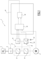
- an electric vehicle 2 comprising an electrical power supply system.
- the electric vehicle 2 may be an electrically-driven railway vehicle.
- the railway vehicle may be a passenger train, or a high-speed train, or a locomotive, or a service vehicle such as a handcar or a shunter, or an urban transport vehicle such as a metro or a tram.
- the vehicle 2 may be a road electric vehicle, such as an electric bus or an electric truck.
- the vehicle 2 comprises an electric powertrain comprising one or more electric motors 4 preferably configured to drive the vehicle while moving along a track.
- the or each motor 4 is mechanically coupled to a load, such as one or more wheels of a bogie or a drive axle.
- a load such as one or more wheels of a bogie or a drive axle.
- the traction chain may comprise one or more loads of a different nature.
- the electrical power system is also configured to power one or more auxiliary equipment of the vehicle 2.
- the auxiliary equipment comprises at least one auxiliary device, or even several auxiliary devices of the vehicle 2, such as a ventilation, heating or air conditioning system, or one or more motors for opening or closing automatic doors of the vehicle, or a lighting system, or a passenger information system, or any other equivalent device, these examples not being limiting.
- a ventilation, heating or air conditioning system or one or more motors for opening or closing automatic doors of the vehicle, or a lighting system, or a passenger information system, or any other equivalent device, these examples not being limiting.
- the electrical power supply system comprises a first energy storage device comprising a hydrogen tank 6 and a fuel cell 8 both on board the vehicle 2.
- a power conversion device 10 is connected to the fuel cell 8 and is configured to transform the electrical voltage delivered by the fuel cell 8 to electrically power the engine 4 and the auxiliary equipment.
- the conversion device 10 comprises a first power converter 12 and a second power converter 14.
- the first converter 12 is connected to the output of the fuel cell 8.
- the first converter 12 is a DC-DC type step-up voltage converter, such as a chopper.
- the second converter 14 is connected to the motor 4.
- it is an inverter which converts the direct voltage delivered by the first converter 12 into an alternating voltage used to power the motor 4.
- the electrical voltage at the terminals of the fuel cell 8 can vary depending on the electrical power required from the fuel cell 8 when it is in operation. In practice, this electrical voltage is lower than the electrical voltage present between the conductors of the internal DC power supply bus (here between the converters 12 and 14).
- the power supply system comprises a second energy storage device comprising a battery 16.
- the battery 16 may comprise a battery of electrochemical accumulators.
- the battery 16 may comprise a set of capacitors or supercapacitors, or any appropriate electricity storage technology.
- a DC/DC output converter such as a step-up chopper.
- the battery 16 has a voltage greater than or equal to 750V DC between its terminals when it is charged.
- the battery 16 is connected to the conversion device 10 to electrically power the motor 4 and the auxiliary equipment.
- the battery 16 is connected to the input of the second converter 14.
- the power supply system may comprise a second DC/DC conversion stage to raise the output voltage to a voltage of 1500V, for example to be compatible with the voltage required by the traction motor.
- the battery 16 can also be recharged by the fuel cell 8 or by electrical energy collected by a collection device of the vehicle 2, such as a pantograph or a collector or any equivalent system.
- the power supply of the auxiliary equipment is provided by an additional power converter 18 which can be powered by the battery 16 and/or by the fuel cell 8 via the conversion device 10.
- the input of the additional converter 18 is connected to the output of the battery 16 and to the output of the first converter 12.
- the additional converter 18 comprises a first output 20 which delivers a direct voltage and a second output 22 which delivers a second alternating voltage, which may be a three-phase electrical voltage.
- the direct voltage is equal to 24 V DC and the alternating voltage is equal to 400 V AC.
- the battery 16 and the fuel cell 8 are capable of storing energy to electrically power at least part of the vehicle 2, in particular to power the engine 4 and/or auxiliary equipment, when the vehicle 2 is not powered by an external power source. This is the case, for example, when the vehicle 2 travels on a portion of track without a catenary or power rail.
- the supervision and regulation of the power supply system, and in particular of the first storage device, which is the primary energy source, and of the second storage device, which is the energy storage system, are carried out automatically by one or more electronic control devices, which may belong to the power supply system.
- the fuel cell 8 is preferably used in addition to the battery 16.
- the battery 16 is preferably used so that its state of charge remains within a predetermined range, for example between 20% and 90% of its maximum capacity, in order to avoid premature wear of the battery or a deterioration in its performance.
- the fuel cell 8 is therefore preferentially used when the electrical power demanded from the battery risks causing a variation in its state of charge outside the predetermined interval.
- battery 16 by its nature, has a shorter response time than fuel cell 8 and better tolerates repeated power variations than fuel cell 8.
- the fuel cell 8 is therefore preferentially used to respond to power calls over long periods of time, rather than to respond quickly to power calls which can vary rapidly and with a high variation amplitude.
- an electronic controller associated with the battery 16 is programmed to calculate a target value of the state of charge, which is recalculated over time as a function of the evolution of the charge of the battery 16 and of the demands imposed on the power supply system by the traction chain and by the auxiliary equipment.
- the electronic controller determines, from the calculated target state of charge value, a first setpoint value for the electrical power that the battery 16 must provide.
- the energy management of the fuel cell 8 is carried out by an electronic control device 24 which is capable of defining a second power setpoint value that the fuel cell 8 must provide so that the power supply system responds to its requests while allowing the battery 16 to reach the first calculated setpoint value.
- control device 24 is programmed to control the fuel cell 8 so that the latter provides an electrical power whose value is optimized, for a given instant, so that the fuel cell 8 operates with maximum efficiency and according to the demands of the electrical power supply system.
- control device 24 is able to automatically control the power supply system according to this second calculated power setpoint, for example by modifying the quantity of air and/or the quantity of hydrogen supplied at the input of the fuel cell 8, to modify the power supplied by the fuel cell 8.
- the control device 24 can also be configured to modify the operation of the conversion device 10, for example by modifying the current setpoint of the first converter 12.
- the control device 24 can also control an electrical switching device making it possible to connect or disconnect the fuel cell 8 from the rest of the power supply system.
- control device 24 is implemented by an electronic circuit, for example mounted on an electronic card.
- control device 24 includes a processor, such as a programmable microcontroller, and computer memory coupled to the processor and forming a computer-readable data storage medium.
- processor such as a programmable microcontroller
- computer memory coupled to the processor and forming a computer-readable data storage medium.
- the memory is a ROM read-only memory, or a RAM, or a non-volatile memory of the EPROM, or EEPROM, or Flash type, or any suitable memory technology, or any possible combination of these memory technologies.
- the memory comprises executable instructions and/or software code in particular for implementing a method in accordance with embodiments of the invention when these instructions and/or this software code are executed by the processor.
- control device 24 comprises a programmable logic component (FPGA) or a dedicated integrated circuit configured to implement such methods.
- FPGA programmable logic component
- control device 24 comprises a first calculation module 26, or energy management module, programmed to determine a value or a range of values indicating the electrical power that the fuel cell 8 must deliver.
- the module 26 is then programmed to calculate the electrical power that the fuel cell should theoretically deliver, based on the determined electrical quantities, but also based on the battery power setpoint.
- Module 26 calculates a minimum value and a maximum value of power that the fuel cell 8 must provide.
- the electrical power that the fuel cell must deliver is between said minimum value and said maximum value.
- the minimum value is equal to the sum of the power required by the drive train and the power required by the auxiliary components from which is subtracted the maximum power that can be delivered by the battery 16, in particular when it is discharging.
- the minimum value is zero if the above quantity is less than zero.
- the maximum value is equal to the sum of the power required by the drive train and the power required by the auxiliary components from which is subtracted the minimum power that can be delivered by the battery 16, in particular when it is discharging.
- the maximum value is zero if the above quantity is less than zero.
- the power that the fuel cell must provide to supplement the power provided by the battery 16 is equal to the power required for the battery to reach the target state of charge, from which is subtracted the power required by the drive train and the power required by the auxiliary devices.
- control device 24 also comprises a second calculation module 28, or optimization module, configured to calculate a target power value that the fuel cell 8 must provide.
- This calculation is carried out here from the power values determined by the first module 26, and as a function of a predetermined efficiency curve expressing the efficiency of the fuel cell 8.
- a predetermined efficiency curve expressing the efficiency of the fuel cell 8.
- Such a curve is for example stored in a memory of the control device 24.
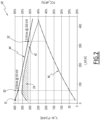
- FIG. 2 represents a graph 40 illustrating an example of operation of the electrical power supply system of the vehicle 2.
- the abscissa axis indicates the total current l_tot, expressed in amperes, delivered by the fuel cell 8.
- the left axis corresponds to either the electrical voltage delivered by the power supply system (curve 44) expressed in Volts, or the power delivered by the power supply system (curve 46), expressed in kW.
- the right axis indicates the energy efficiency FCC_eff of the fuel cell 8 (curve 42).
- the curves 44, 46 indicate, respectively, the electrical voltage of the power supply system and the total power delivered by the power supply system.
- Point 50 represents the power giving the maximum efficiency of the fuel cell corresponding here to a voltage of 379 V DC for a power of 50kW.
- the first point 51 represents a first power limit, corresponding here to a voltage of 390 V DC for a power of 20 kW.
- the second point 52 represents a second power limit, associated with a second limit value, corresponding here to a voltage of 315 V DC for a power of 200 kW.
- Zone 54 designates an operating zone of the fuel cell 8 in which it has a maximum or optimal efficiency. Zone 54 corresponds to a set of operating points of the fuel cell 8 for which the values are between the first limit 51 and the second limit 52 and whose upper values are bounded by the energy efficiency curve 42 of the fuel cell 8.
- the module 28 selects an operating point included in the zone 54, preferably corresponding to the maximum of the efficiency curve 42 in the zone 54 (point 50).
- the fuel cell operates at a level equal to the maximum efficiency point as determined by efficiency curve 42, or at a level close to that maximum efficiency point, such as within plus or minus 10% of the maximum efficiency point.
- the efficiency curve 42 can be predefined in advance, for example in the factory from specifications of the fuel cell 8. Alternatively, the efficiency curve 42 can be calculated by the device 24 and updated over time depending on the operation of the power supply system and/or depending on the wear of the fuel cell 8.
- the control device 24 controls the disconnection of the fuel cell 8 or does not start the chopper 12.
- the traction or braking command causing the required electrical power variation may need to be throttled by the control device 24 in the extreme case where the requested power is too high and the electrical power system cannot meet the demand, for example because neither the fuel cell 8 nor the battery 16 can provide the required power.
- the control device 24 may also instruct the auxiliary equipment to reduce its electrical consumption.
- the method begins at step 100, for example in response to a control command issued by a train driver, for example an acceleration or braking command issued by means of a traction controller and which has the effect of modifying the electrical consumption of the engine 4 and/or the auxiliary equipment.
- a control command issued by a train driver for example an acceleration or braking command issued by means of a traction controller and which has the effect of modifying the electrical consumption of the engine 4 and/or the auxiliary equipment.
- step 100 may be performed regularly, for example with a predefined periodicity.
- step 100 can be executed when the vehicle 2 reaches a precise geographical position, for example when the vehicle 2 passes through specific points of a predefined trajectory during its movement.
- control device 24 receives information, namely a first setpoint value corresponding to the electrical power that the battery must provide so that the power supply system can power the traction chain and the auxiliary equipment.
- the module 26 determines the electrical power required by the drive train and more precisely by the motor(s) 4 as well as the electrical power required by the auxiliary equipment.
- the module 26 determines the state of the battery, in particular the state of charge of the battery and the maximum power available for charging or the maximum power available for discharging.
- the module 26 calculates the maximum value and the minimum value of electrical power that the fuel cell 8 must deliver as a function of the state of the power supply system and the demands that it must face, as determined during steps 102 and 104.
- the second module 28 calculates the optimized value of electrical power that the fuel cell must provide from the maximum value and the minimum value of electrical power calculated by the module 26 and according to the efficiency curve 42.
- control device 24 uses the optimized electrical power value thus calculated as a setpoint to control the electrical power supply system accordingly, so that the fuel cell 8 supplies the corresponding electrical power or, if necessary, is disconnected from the rest of the electrical power supply system.
- the optimization of the operation of the fuel cell makes it possible to reduce the consumption of hydrogen, without degrading the operation of the fuel cell or its capacity to provide an electrical power supply when the vehicle needs it.
- the autonomy of the vehicle is increased without needing to install a larger tank, which would be more expensive, more massive and more bulky.
Landscapes
- Engineering & Computer Science (AREA)
- Life Sciences & Earth Sciences (AREA)
- Sustainable Development (AREA)
- Sustainable Energy (AREA)
- Chemical & Material Sciences (AREA)
- Transportation (AREA)
- Mechanical Engineering (AREA)
- Power Engineering (AREA)
- Chemical Kinetics & Catalysis (AREA)
- Electrochemistry (AREA)
- General Chemical & Material Sciences (AREA)
- Manufacturing & Machinery (AREA)
- Combustion & Propulsion (AREA)
- Evolutionary Computation (AREA)
- Health & Medical Sciences (AREA)
- Artificial Intelligence (AREA)
- Automation & Control Theory (AREA)
- Computing Systems (AREA)
- Microelectronics & Electronic Packaging (AREA)
- Fuzzy Systems (AREA)
- Medical Informatics (AREA)
- Software Systems (AREA)
- Theoretical Computer Science (AREA)
- Fuel Cell (AREA)
- Electric Propulsion And Braking For Vehicles (AREA)
Claims (8)
- Steuerungsverfahren eines Stromversorgungssystems für ein Elektrofahrzeug (2), umfassend eine Batterie (16), eine Brennstoffzelle (8) und eine Leistungsumwandlungsvorrichtung (10), die mit der Batterie (16) und der Brennstoffzelle (8) verbunden ist, wobei das Stromversorgungssystem konfiguriert ist, um einen elektrischen Antriebsstrang (4) des Fahrzeugs und mindestens ein Hilfsgerät zu versorgen, das Verfahren umfassend Schritte, die aus Folgendem bestehen:- Erfassen (100) eines ersten Leistungsvorgabewerts, der der elektrischen Leistung entspricht, die die Batterie (16) bereitstellen soll, wobei der erste Leistungsvorgabewert anhand eines Zielwerts des Ladezustands der Batterie (16) bestimmt wird;- Bestimmen (102) der elektrischen Leistung, die von dem Antriebsstrang benötigt wird, und der elektrischen Leistung, die von dem mindestens einen Hilfsgerät benötigt wird;- Bestimmen (104) des Zustands der Batterie, insbesondere des Ladezustands der Batterie und der maximal verfügbaren Leistung, die die Batterie bereitstellen kann;- Berechnen (106) mindestens eines Werts elektrischer Leistung, die die Brennstoffzelle (8) abhängig von dem Zustand der Batterie und der von der Antriebskette und dem mindestens einen Hilfsgerät benötigten elektrischen Leistung bereitstellen soll;- Berechnen (108), anhand des berechneten Werts elektrischer Leistung, eines zweiten Vorgabewerts elektrischer Leistung, die die Brennstoffzelle (8) bereitstellen soll, damit die Brennstoffzelle (8) auf oder nahe ihrem maximalen Wirkungsgradpunkt betrieben wird;- Steuern (100) des Versorgungssystems abhängig von dem berechneten zweiten elektrischen Leistungsvorgabewert,dadurch gekennzeichnet, dass ein Berechnen (106) mindestens eines Werts elektrischer Leistung, die von der Brennstoffzelle (8) bereitgestellt werden soll, das Berechnen eines Minimalwerts und eines Maximalwerts der Leistung, die die Brennstoffzelle bereitstellen soll, umfasst, wobei der zweite Vorgabewert elektrischer Leistung zwischen dem Minimalwert und dem Maximalwert liegt,dass der berechnete Wert elektrischer Leistung der Leistung entspricht, die die Brennstoffzelle bereitstellen soll, um die von der Batterie bereitgestellte Leistung zu ergänzen, wobei der berechnete Wert elektrischer Leistung gleich wie die Leistung ist, die die Batterie benötigt, um den Sollwert des Ladezustands zu erreichen, wovon die von dem Antriebsstrang benötigte Leistung und die von dem mindestens einen Hilfsgerät benötigte Leistung abgezogen werden;und dass die Berechnung des zweiten Leistungsvorgabewerts anhand einer vordefinierten Wirkungsgradkurve (42) der Brennstoffzelle (8) erfolgt, indem ein Betriebspunkt (50) der Brennstoffzelle ausgewählt wird, die dem Maximum der Wirkungsgradkurve (42) in einem Betriebsbereich (54) zwischen dem zuvor berechneten Minimalwert und dem Maximalwert entspricht, und wobei mindestens mehrere der folgenden Kriterien erfüllt sind:- die von der Batterie (16) bereitgestellte elektrische Leistung konvergiert in Richtung des ersten Vorgabewerts,- die von einem Fahrer erteilten Befehlsbefehle werden befolgt,- das mindestens eine Hilfsgerät wird versorgt, und- die Änderungen der von der Brennstoffzelle (8) geforderten Leistung sind lang im Verlauf der Zeit.
- Verfahren nach Anspruch 1, wobei der Minimalwert gleich wie die Summe aus der von dem Antriebsstrang benötigten Leistung und der von dem mindestens einen Hilfsgerät benötigten Leistung ist, wovon die maximale Leistung abgezogen wird, die von der Batterie (16) bereitgestellt werden kann.
- Verfahren nach Anspruch 1 oder Anspruch 2, wobei der Maximalwert gleich wie die Summe aus der von dem Antriebsstrang benötigten Leistung und der von dem mindestens einen Hilfsgerät benötigten Leistung ist, wovon die minimale Leistung abgezogen wird, die von der Batterie bereitgestellt werden kann.
- Verfahren nach einem der vorherigen Ansprüche, wobei der erste Leistungsvorgabewert zuvor abhängig von dem Sollwert des Ladezustands der Batterie berechnet wird.
- Verfahren nach einem der vorherigen Ansprüche, wobei das Verfahren als Reaktion auf einen von einem Fahrer des Fahrzeugs erteilten Steuerbefehl durchgeführt wird, beispielsweise ein Beschleunigungs- oder Bremsbefehl, der dazu führt, dass der Stromverbrauch des Antriebsstrangs und/oder des mindestens einen Hilfsgeräts geändert wird.
- Verfahren nach einem der vorherigen Ansprüche, wobei der zweite Leistungsvorgabewert gewählt wird, damit, wenn die Brennstoffzelle eine berechnete elektrische Leistung bereitstellt, die dem zweiten Leistungsvorgabewert entspricht, die Batterie (16) eine elektrische Leistung bereitstellt, die dem ersten berechneten Vorgabewert entspricht.
- Stromversorgungssystem eines für ein Elektrofahrzeug (2), umfassend eine Batterie (16), eine Brennstoffzelle (8) und eine Leistungsumwandlungsvorrichtung (10), die mit der Batterie (16) und der Brennstoffzelle (8) verbunden ist, wobei das Stromversorgungssystem konfiguriert ist, um einen elektrischen Antriebsstrang (4) des Fahrzeugs und mindestens ein Hilfsgerät zu versorgen, das Stromversorgungssystem umfassend eine elektronische Steuerungsvorrichtung (24), die programmiert ist, um Schritte durchzuführen, die aus Folgendem bestehen:- Erfassen (100) eines ersten Leistungsvorgabewerts, der der elektrischen Leistung entspricht, die die Batterie (16) bereitstellen soll, wobei der erste Leistungssollwert anhand eines Zielwerts des Ladezustands der Batterie (16) bestimmt wird;- Bestimmen (102) der elektrischen Leistung, die von dem Antriebsstrang benötigt wird, und der elektrischen Leistung, die von dem mindestens einen Hilfsgerät benötigt wird;- Bestimmen (104) des Zustands der Batterie, insbesondere des Ladezustands der Batterie und der maximal verfügbaren Leistung, die die Batterie bereitstellen kann;- Berechnen (106) mindestens eines Werts elektrischer Leistung, die die Brennstoffzelle (8) abhängig von dem Zustand der Batterie und der von der Antriebskette und dem mindestens einen Hilfsgerät benötigten elektrischen Leistung bereitstellen soll;- Berechnen (108), anhand des berechneten Werts elektrischer Leistung, eines zweiten Vorgabewerts elektrischer Leistung, die die Brennstoffzelle (8) bereitstellen soll, damit die Brennstoffzelle (8) auf oder nahe ihrem maximalen Wirkungsgradpunkt betrieben wird;- Steuern (100) des Versorgungssystems abhängig von dem berechneten zweiten elektrischen Leistungsvorgabewert;dadurch gekennzeichnet, dass ein Berechnen (106) mindestens eines Werts elektrischer Leistung, die von der Brennstoffzelle (8) bereitgestellt werden soll, das Berechnen eines Minimalwerts und eines Maximalwerts der Leistung, die die Brennstoffzelle bereitstellen soll, umfasst, wobei der zweite Vorgabewert elektrischer Leistung zwischen dem Minimalwert und dem Maximalwert liegt,dass der berechnete Wert elektrischer Leistung der Leistung entspricht, die die Brennstoffzelle bereitstellen soll, um die von der Batterie bereitgestellte Leistung zu ergänzen, wobei der berechnete Wert elektrischer Leistung gleich wie die Leistung ist, die die Batterie benötigt, um den Sollwert des Ladezustands zu erreichen, wovon die von dem Antriebsstrang benötigte Leistung und die von dem mindestens einen Hilfsgerät benötigte Leistung abgezogen werden,und dass die Berechnung des zweiten Vorgabewerts anhand einer vordefinierten Wirkungsgradkurve (42) der Brennstoffzelle (8) erfolgt, indem ein Betriebspunkt der Brennstoffzelle ausgewählt wird, die dem Maximum der Wirkungsgradkurve (42) in einem Betriebsbereich zwischen dem zuvor berechneten Minimalwert und dem Maximalwert entspricht, und wobei mindestens mehrere der folgenden Kriterien erfüllt sind:- die von der Batterie (16) bereitgestellte elektrische Leistung konvergiert in Richtung des ersten Vorgabewerts,- die von einem Fahrer erteilten Befehlsbefehle werden befolgt,- das mindestens eine Hilfsgerät wird versorgt, und- die Änderungen der von der Brennstoffzelle (8) geforderten Leistung sind lang im Verlauf der Zeit.
- Elektrofahrzeug (2), umfassend ein Stromversorgungssystem nach Anspruch 7.
Applications Claiming Priority (1)
| Application Number | Priority Date | Filing Date | Title |
|---|---|---|---|
| FR2012384A FR3116768B1 (fr) | 2020-11-30 | 2020-11-30 | Système d’alimentation électrique et procédé pour piloter un tel système d’alimentation électrique |
Publications (2)
| Publication Number | Publication Date |
|---|---|
| EP4005863A1 EP4005863A1 (de) | 2022-06-01 |
| EP4005863B1 true EP4005863B1 (de) | 2024-11-13 |
Family
ID=74125538
Family Applications (1)
| Application Number | Title | Priority Date | Filing Date |
|---|---|---|---|
| EP21211022.5A Active EP4005863B1 (de) | 2020-11-30 | 2021-11-29 | Stromversorgungssystem und verfahren zur steuerung eines solchen stromversorgungssystems |
Country Status (5)
| Country | Link |
|---|---|
| US (1) | US12296696B2 (de) |
| EP (1) | EP4005863B1 (de) |
| CA (1) | CA3140785A1 (de) |
| DK (1) | DK4005863T3 (de) |
| FR (1) | FR3116768B1 (de) |
Family Cites Families (9)
| Publication number | Priority date | Publication date | Assignee | Title |
|---|---|---|---|---|
| JP2002141073A (ja) * | 2000-10-31 | 2002-05-17 | Nissan Motor Co Ltd | 移動体用燃料電池システム |
| DE10233821A1 (de) * | 2002-07-25 | 2004-02-05 | Daimlerchrysler Ag | Verfahren und Anordnung zur Steuerung der Energieversorgung einer wenigstens einen elektrischen Antriebsmotor aufweisenden, mobilen Vorrichtung mit einem hybriden Energiesystem, das ein Brennstoffzellensystem und ein dynamisches Energiesystem enthält |
| US8847426B2 (en) * | 2007-11-02 | 2014-09-30 | GM Global Technology Operations LLC | Method for managing electric power in a powertrain system |
| JP5622693B2 (ja) * | 2011-09-09 | 2014-11-12 | 本田技研工業株式会社 | 燃料電池車両 |
| JP6040724B2 (ja) * | 2012-03-13 | 2016-12-07 | 日産自動車株式会社 | バッテリの残存容量算出装置及びバッテリの残存容量算出方法 |
| JP5910439B2 (ja) * | 2012-09-28 | 2016-04-27 | 三菱自動車工業株式会社 | 電力制御装置 |
| KR102507227B1 (ko) * | 2017-11-27 | 2023-03-08 | 현대자동차주식회사 | 연료전지 차량의 전력 분배 시스템 및 방법 |
| JP7054629B2 (ja) * | 2018-01-22 | 2022-04-14 | 本田技研工業株式会社 | 燃料電池車両 |
| JP7159929B2 (ja) * | 2019-03-14 | 2022-10-25 | トヨタ自動車株式会社 | 燃料電池システム |
-
2020
- 2020-11-30 FR FR2012384A patent/FR3116768B1/fr active Active
-
2021
- 2021-11-29 DK DK21211022.5T patent/DK4005863T3/da active
- 2021-11-29 EP EP21211022.5A patent/EP4005863B1/de active Active
- 2021-11-30 CA CA3140785A patent/CA3140785A1/fr active Pending
- 2021-11-30 US US17/538,087 patent/US12296696B2/en active Active
Also Published As
| Publication number | Publication date |
|---|---|
| FR3116768B1 (fr) | 2023-02-10 |
| EP4005863A1 (de) | 2022-06-01 |
| FR3116768A1 (fr) | 2022-06-03 |
| CA3140785A1 (fr) | 2022-05-30 |
| US12296696B2 (en) | 2025-05-13 |
| US20220169128A1 (en) | 2022-06-02 |
| DK4005863T3 (da) | 2025-01-06 |
Similar Documents
| Publication | Publication Date | Title |
|---|---|---|
| US7866425B2 (en) | Hybrid electric propulsion system and method | |
| CN100444495C (zh) | 电池用电力电路 | |
| US8022674B2 (en) | State of charge control method and systems for vehicles | |
| KR102660349B1 (ko) | 배터리 충전 시스템 및 방법 | |
| JPH11252710A (ja) | 再生的制動の間はバッテリーに対し減少させた補助動力によるハイブリッド電気自動車 | |
| EP2715909A2 (de) | Verfahren zur wiederaufladung eines fahrzeugbatteriepaares mit unterschiedlichen nennspannungen und zugehöriges system | |
| EP2707242A2 (de) | Vorrichtung und verfahren zur verwaltung der elektrischen bremsen eines fahrzeugs | |
| JP2007510567A (ja) | ハイブリッド駆動装置を備えた車両におけるエネルギ蓄積器の充電状態の制御方法 | |
| FR2965128B1 (fr) | Procede et dispositif de gestion d'un generateur d'un systeme de recuperation d'energie d'un vehicule automobile | |
| EP1765631B1 (de) | Verwendung einer stromversorgungsvorrichtung, verfahren zur stromversorgung von stromverbrauchern eines triebfahrzeuges und datenträger für dieses verfahren | |
| EP4005863B1 (de) | Stromversorgungssystem und verfahren zur steuerung eines solchen stromversorgungssystems | |
| FR2936207A1 (fr) | Procede et dispositif de controle d'un stockeur d'energie pour vehicule hybride. | |
| US9190939B2 (en) | Device and method for managing the electric braking of a vehicle | |
| WO2010023664A1 (en) | Diesel electrical vehicle | |
| EP4043270A1 (de) | Stromversorgungssystem, entsprechendes verfahren und computerprogramm | |
| CN111204327B (zh) | 用于运行机动车中的混合驱动系统的方法和装置 | |
| FR2974041A1 (fr) | Systeme d'alimentation embarque dans un vehicule, procede d'alimentation electrique et vehicule associes | |
| EP3750377B1 (de) | Verfahren zur steuerung der leistungsversorgung von elektrischen heizmitteln eines systems in abhängigkeit von der verfügbaren elektrischen leistung und dem bedarf | |
| FR3128176A1 (fr) | Procede de regeneration d’une batterie | |
| FR2988673A1 (fr) | Procede de gestion electrique d'un vehicule automobile et vehicule automobile mettant en oeuvre un tel procede | |
| EP2670620A1 (de) | Verfahren und system zur verwaltung der energie eines schienenfahrzeugs | |
| EP2113435A1 (de) | Verfahren und Vorrichtung zur Steuerung eines Energiespeichers für ein Hybridfahrzeug | |
| JP2017093192A (ja) | 車両の電源装置 | |
| FR2988672A1 (fr) | Procede de gestion electrique d'un vehicule automobile et vehicule automobile mettant en oeuvre un tel procede |
Legal Events
| Date | Code | Title | Description |
|---|---|---|---|
| PUAI | Public reference made under article 153(3) epc to a published international application that has entered the european phase |
Free format text: ORIGINAL CODE: 0009012 |
|
| STAA | Information on the status of an ep patent application or granted ep patent |
Free format text: STATUS: THE APPLICATION HAS BEEN PUBLISHED |
|
| STAA | Information on the status of an ep patent application or granted ep patent |
Free format text: STATUS: REQUEST FOR EXAMINATION WAS MADE |
|
| AK | Designated contracting states |
Kind code of ref document: A1 Designated state(s): AL AT BE BG CH CY CZ DE DK EE ES FI FR GB GR HR HU IE IS IT LI LT LU LV MC MK MT NL NO PL PT RO RS SE SI SK SM TR |
|
| 17P | Request for examination filed |
Effective date: 20220511 |
|
| RBV | Designated contracting states (corrected) |
Designated state(s): AL AT BE BG CH CY CZ DE DK EE ES FI FR GB GR HR HU IE IS IT LI LT LU LV MC MK MT NL NO PL PT RO RS SE SI SK SM TR |
|
| STAA | Information on the status of an ep patent application or granted ep patent |
Free format text: STATUS: EXAMINATION IS IN PROGRESS |
|
| P01 | Opt-out of the competence of the unified patent court (upc) registered |
Effective date: 20230823 |
|
| 17Q | First examination report despatched |
Effective date: 20230831 |
|
| RAP1 | Party data changed (applicant data changed or rights of an application transferred) |
Owner name: ALSTOM HOLDINGS |
|
| RIC1 | Information provided on ipc code assigned before grant |
Ipc: H01M 8/04537 20160101ALI20240502BHEP Ipc: B60L 1/00 20060101ALI20240502BHEP Ipc: H01M 8/04992 20160101ALI20240502BHEP Ipc: H01M 8/04858 20160101ALI20240502BHEP Ipc: H01M 16/00 20060101ALI20240502BHEP Ipc: H01M 10/48 20060101ALI20240502BHEP Ipc: H01M 10/44 20060101ALI20240502BHEP Ipc: H01M 10/42 20060101ALI20240502BHEP Ipc: B60L 58/40 20190101AFI20240502BHEP |
|
| GRAP | Despatch of communication of intention to grant a patent |
Free format text: ORIGINAL CODE: EPIDOSNIGR1 |
|
| STAA | Information on the status of an ep patent application or granted ep patent |
Free format text: STATUS: GRANT OF PATENT IS INTENDED |
|
| INTG | Intention to grant announced |
Effective date: 20240612 |
|
| GRAS | Grant fee paid |
Free format text: ORIGINAL CODE: EPIDOSNIGR3 |
|
| GRAA | (expected) grant |
Free format text: ORIGINAL CODE: 0009210 |
|
| STAA | Information on the status of an ep patent application or granted ep patent |
Free format text: STATUS: THE PATENT HAS BEEN GRANTED |
|
| AK | Designated contracting states |
Kind code of ref document: B1 Designated state(s): AL AT BE BG CH CY CZ DE DK EE ES FI FR GB GR HR HU IE IS IT LI LT LU LV MC MK MT NL NO PL PT RO RS SE SI SK SM TR |
|
| REG | Reference to a national code |
Ref country code: GB Ref legal event code: FG4D Free format text: NOT ENGLISH |
|
| REG | Reference to a national code |
Ref country code: CH Ref legal event code: EP |
|
| REG | Reference to a national code |
Ref country code: IE Ref legal event code: FG4D Free format text: LANGUAGE OF EP DOCUMENT: FRENCH |
|
| REG | Reference to a national code |
Ref country code: DE Ref legal event code: R096 Ref document number: 602021021729 Country of ref document: DE |
|
| REG | Reference to a national code |
Ref country code: DK Ref legal event code: T3 Effective date: 20250103 |
|
| REG | Reference to a national code |
Ref country code: SE Ref legal event code: TRGR |
|
| REG | Reference to a national code |
Ref country code: LT Ref legal event code: MG9D |
|
| REG | Reference to a national code |
Ref country code: NL Ref legal event code: MP Effective date: 20241113 |
|
| PG25 | Lapsed in a contracting state [announced via postgrant information from national office to epo] |
Ref country code: PT Free format text: LAPSE BECAUSE OF FAILURE TO SUBMIT A TRANSLATION OF THE DESCRIPTION OR TO PAY THE FEE WITHIN THE PRESCRIBED TIME-LIMIT Effective date: 20250313 Ref country code: HR Free format text: LAPSE BECAUSE OF FAILURE TO SUBMIT A TRANSLATION OF THE DESCRIPTION OR TO PAY THE FEE WITHIN THE PRESCRIBED TIME-LIMIT Effective date: 20241113 Ref country code: IS Free format text: LAPSE BECAUSE OF FAILURE TO SUBMIT A TRANSLATION OF THE DESCRIPTION OR TO PAY THE FEE WITHIN THE PRESCRIBED TIME-LIMIT Effective date: 20250313 |
|
| PG25 | Lapsed in a contracting state [announced via postgrant information from national office to epo] |
Ref country code: FI Free format text: LAPSE BECAUSE OF FAILURE TO SUBMIT A TRANSLATION OF THE DESCRIPTION OR TO PAY THE FEE WITHIN THE PRESCRIBED TIME-LIMIT Effective date: 20241113 Ref country code: NL Free format text: LAPSE BECAUSE OF FAILURE TO SUBMIT A TRANSLATION OF THE DESCRIPTION OR TO PAY THE FEE WITHIN THE PRESCRIBED TIME-LIMIT Effective date: 20241113 |
|
| REG | Reference to a national code |
Ref country code: AT Ref legal event code: MK05 Ref document number: 1741455 Country of ref document: AT Kind code of ref document: T Effective date: 20241113 |
|
| PG25 | Lapsed in a contracting state [announced via postgrant information from national office to epo] |
Ref country code: BG Free format text: LAPSE BECAUSE OF FAILURE TO SUBMIT A TRANSLATION OF THE DESCRIPTION OR TO PAY THE FEE WITHIN THE PRESCRIBED TIME-LIMIT Effective date: 20241113 |
|
| PG25 | Lapsed in a contracting state [announced via postgrant information from national office to epo] |
Ref country code: ES Free format text: LAPSE BECAUSE OF FAILURE TO SUBMIT A TRANSLATION OF THE DESCRIPTION OR TO PAY THE FEE WITHIN THE PRESCRIBED TIME-LIMIT Effective date: 20241113 |
|
| PG25 | Lapsed in a contracting state [announced via postgrant information from national office to epo] |
Ref country code: LV Free format text: LAPSE BECAUSE OF FAILURE TO SUBMIT A TRANSLATION OF THE DESCRIPTION OR TO PAY THE FEE WITHIN THE PRESCRIBED TIME-LIMIT Effective date: 20241113 Ref country code: GR Free format text: LAPSE BECAUSE OF FAILURE TO SUBMIT A TRANSLATION OF THE DESCRIPTION OR TO PAY THE FEE WITHIN THE PRESCRIBED TIME-LIMIT Effective date: 20250214 Ref country code: AT Free format text: LAPSE BECAUSE OF FAILURE TO SUBMIT A TRANSLATION OF THE DESCRIPTION OR TO PAY THE FEE WITHIN THE PRESCRIBED TIME-LIMIT Effective date: 20241113 |
|
| PG25 | Lapsed in a contracting state [announced via postgrant information from national office to epo] |
Ref country code: PL Free format text: LAPSE BECAUSE OF FAILURE TO SUBMIT A TRANSLATION OF THE DESCRIPTION OR TO PAY THE FEE WITHIN THE PRESCRIBED TIME-LIMIT Effective date: 20241113 |
|
| PG25 | Lapsed in a contracting state [announced via postgrant information from national office to epo] |
Ref country code: IT Free format text: LAPSE BECAUSE OF NON-PAYMENT OF DUE FEES Effective date: 20241129 |
|
| PG25 | Lapsed in a contracting state [announced via postgrant information from national office to epo] |
Ref country code: RS Free format text: LAPSE BECAUSE OF FAILURE TO SUBMIT A TRANSLATION OF THE DESCRIPTION OR TO PAY THE FEE WITHIN THE PRESCRIBED TIME-LIMIT Effective date: 20250213 |
|
| REG | Reference to a national code |
Ref country code: CH Ref legal event code: PL |
|
| PG25 | Lapsed in a contracting state [announced via postgrant information from national office to epo] |
Ref country code: SM Free format text: LAPSE BECAUSE OF FAILURE TO SUBMIT A TRANSLATION OF THE DESCRIPTION OR TO PAY THE FEE WITHIN THE PRESCRIBED TIME-LIMIT Effective date: 20241113 |
|
| PG25 | Lapsed in a contracting state [announced via postgrant information from national office to epo] |
Ref country code: LU Free format text: LAPSE BECAUSE OF NON-PAYMENT OF DUE FEES Effective date: 20241129 |
|
| REG | Reference to a national code |
Ref country code: CH Ref legal event code: PL |
|
| PG25 | Lapsed in a contracting state [announced via postgrant information from national office to epo] |
Ref country code: EE Free format text: LAPSE BECAUSE OF FAILURE TO SUBMIT A TRANSLATION OF THE DESCRIPTION OR TO PAY THE FEE WITHIN THE PRESCRIBED TIME-LIMIT Effective date: 20241113 |
|
| PG25 | Lapsed in a contracting state [announced via postgrant information from national office to epo] |
Ref country code: CH Free format text: LAPSE BECAUSE OF NON-PAYMENT OF DUE FEES Effective date: 20241130 |
|
| PG25 | Lapsed in a contracting state [announced via postgrant information from national office to epo] |
Ref country code: RO Free format text: LAPSE BECAUSE OF FAILURE TO SUBMIT A TRANSLATION OF THE DESCRIPTION OR TO PAY THE FEE WITHIN THE PRESCRIBED TIME-LIMIT Effective date: 20241113 |
|
| PG25 | Lapsed in a contracting state [announced via postgrant information from national office to epo] |
Ref country code: SK Free format text: LAPSE BECAUSE OF FAILURE TO SUBMIT A TRANSLATION OF THE DESCRIPTION OR TO PAY THE FEE WITHIN THE PRESCRIBED TIME-LIMIT Effective date: 20241113 |
|
| PG25 | Lapsed in a contracting state [announced via postgrant information from national office to epo] |
Ref country code: CZ Free format text: LAPSE BECAUSE OF FAILURE TO SUBMIT A TRANSLATION OF THE DESCRIPTION OR TO PAY THE FEE WITHIN THE PRESCRIBED TIME-LIMIT Effective date: 20241113 |
|
| REG | Reference to a national code |
Ref country code: DE Ref legal event code: R097 Ref document number: 602021021729 Country of ref document: DE |
|
| REG | Reference to a national code |
Ref country code: BE Ref legal event code: MM Effective date: 20241130 |
|
| PG25 | Lapsed in a contracting state [announced via postgrant information from national office to epo] |
Ref country code: MC Free format text: LAPSE BECAUSE OF FAILURE TO SUBMIT A TRANSLATION OF THE DESCRIPTION OR TO PAY THE FEE WITHIN THE PRESCRIBED TIME-LIMIT Effective date: 20241113 |
|
| PLBE | No opposition filed within time limit |
Free format text: ORIGINAL CODE: 0009261 |
|
| STAA | Information on the status of an ep patent application or granted ep patent |
Free format text: STATUS: NO OPPOSITION FILED WITHIN TIME LIMIT |
|
| PG25 | Lapsed in a contracting state [announced via postgrant information from national office to epo] |
Ref country code: BE Free format text: LAPSE BECAUSE OF NON-PAYMENT OF DUE FEES Effective date: 20241130 |
|
| 26N | No opposition filed |
Effective date: 20250814 |
|
| PG25 | Lapsed in a contracting state [announced via postgrant information from national office to epo] |
Ref country code: IE Free format text: LAPSE BECAUSE OF NON-PAYMENT OF DUE FEES Effective date: 20241129 |
|
| PGFP | Annual fee paid to national office [announced via postgrant information from national office to epo] |
Ref country code: DE Payment date: 20251119 Year of fee payment: 5 |
|
| PGFP | Annual fee paid to national office [announced via postgrant information from national office to epo] |
Ref country code: NO Payment date: 20251125 Year of fee payment: 5 |
|
| PG25 | Lapsed in a contracting state [announced via postgrant information from national office to epo] |
Ref country code: IT Free format text: LAPSE BECAUSE OF NON-PAYMENT OF DUE FEES Effective date: 20241129 |
|
| PGFP | Annual fee paid to national office [announced via postgrant information from national office to epo] |
Ref country code: IT Payment date: 20251125 Year of fee payment: 5 Ref country code: DK Payment date: 20251125 Year of fee payment: 5 |
|
| PGRI | Patent reinstated in contracting state [announced from national office to epo] |
Ref country code: IT Effective date: 20241130 |
|
| PGFP | Annual fee paid to national office [announced via postgrant information from national office to epo] |
Ref country code: FR Payment date: 20251126 Year of fee payment: 5 |
|
| PGFP | Annual fee paid to national office [announced via postgrant information from national office to epo] |
Ref country code: SE Payment date: 20251119 Year of fee payment: 5 |
|
| PG25 | Lapsed in a contracting state [announced via postgrant information from national office to epo] |
Ref country code: HU Free format text: LAPSE BECAUSE OF FAILURE TO SUBMIT A TRANSLATION OF THE DESCRIPTION OR TO PAY THE FEE WITHIN THE PRESCRIBED TIME-LIMIT; INVALID AB INITIO Effective date: 20211129 |
|
| PG25 | Lapsed in a contracting state [announced via postgrant information from national office to epo] |
Ref country code: CY Free format text: LAPSE BECAUSE OF FAILURE TO SUBMIT A TRANSLATION OF THE DESCRIPTION OR TO PAY THE FEE WITHIN THE PRESCRIBED TIME-LIMIT; INVALID AB INITIO Effective date: 20211129 |