EP4005871B1 - Fahrzeugsteuerungssystem - Google Patents
Fahrzeugsteuerungssystem Download PDFInfo
- Publication number
- EP4005871B1 EP4005871B1 EP20847517.8A EP20847517A EP4005871B1 EP 4005871 B1 EP4005871 B1 EP 4005871B1 EP 20847517 A EP20847517 A EP 20847517A EP 4005871 B1 EP4005871 B1 EP 4005871B1
- Authority
- EP
- European Patent Office
- Prior art keywords
- zone
- zone ecu
- ecu
- central processing
- processing unit
- Prior art date
- Legal status (The legal status is an assumption and is not a legal conclusion. Google has not performed a legal analysis and makes no representation as to the accuracy of the status listed.)
- Active
Links
Images




Classifications
-
- B—PERFORMING OPERATIONS; TRANSPORTING
- B60—VEHICLES IN GENERAL
- B60R—VEHICLES, VEHICLE FITTINGS, OR VEHICLE PARTS, NOT OTHERWISE PROVIDED FOR
- B60R16/00—Electric or fluid circuits specially adapted for vehicles and not otherwise provided for; Arrangement of elements of electric or fluid circuits specially adapted for vehicles and not otherwise provided for
- B60R16/02—Electric or fluid circuits specially adapted for vehicles and not otherwise provided for; Arrangement of elements of electric or fluid circuits specially adapted for vehicles and not otherwise provided for electric constitutive elements
- B60R16/023—Electric or fluid circuits specially adapted for vehicles and not otherwise provided for; Arrangement of elements of electric or fluid circuits specially adapted for vehicles and not otherwise provided for electric constitutive elements for transmission of signals between vehicle parts or subsystems
- B60R16/0231—Circuits relating to the driving or the functioning of the vehicle
-
- H—ELECTRICITY
- H04—ELECTRIC COMMUNICATION TECHNIQUE
- H04L—TRANSMISSION OF DIGITAL INFORMATION, e.g. TELEGRAPHIC COMMUNICATION
- H04L12/00—Data switching networks
- H04L12/28—Data switching networks characterised by path configuration, e.g. LAN [Local Area Networks] or WAN [Wide Area Networks]
- H04L12/40—Bus networks
- H04L12/403—Bus networks with centralised control, e.g. polling
-
- B—PERFORMING OPERATIONS; TRANSPORTING
- B60—VEHICLES IN GENERAL
- B60Q—ARRANGEMENT OF SIGNALLING OR LIGHTING DEVICES, THE MOUNTING OR SUPPORTING THEREOF OR CIRCUITS THEREFOR, FOR VEHICLES IN GENERAL
- B60Q1/00—Arrangement of optical signalling or lighting devices, the mounting or supporting thereof or circuits therefor
- B60Q1/26—Arrangement of optical signalling or lighting devices, the mounting or supporting thereof or circuits therefor the devices being primarily intended to indicate the vehicle, or parts thereof, or to give signals, to other traffic
- B60Q1/34—Arrangement of optical signalling or lighting devices, the mounting or supporting thereof or circuits therefor the devices being primarily intended to indicate the vehicle, or parts thereof, or to give signals, to other traffic for indicating change of drive direction
-
- B—PERFORMING OPERATIONS; TRANSPORTING
- B60—VEHICLES IN GENERAL
- B60Q—ARRANGEMENT OF SIGNALLING OR LIGHTING DEVICES, THE MOUNTING OR SUPPORTING THEREOF OR CIRCUITS THEREFOR, FOR VEHICLES IN GENERAL
- B60Q1/00—Arrangement of optical signalling or lighting devices, the mounting or supporting thereof or circuits therefor
- B60Q1/26—Arrangement of optical signalling or lighting devices, the mounting or supporting thereof or circuits therefor the devices being primarily intended to indicate the vehicle, or parts thereof, or to give signals, to other traffic
- B60Q1/34—Arrangement of optical signalling or lighting devices, the mounting or supporting thereof or circuits therefor the devices being primarily intended to indicate the vehicle, or parts thereof, or to give signals, to other traffic for indicating change of drive direction
- B60Q1/38—Arrangement of optical signalling or lighting devices, the mounting or supporting thereof or circuits therefor the devices being primarily intended to indicate the vehicle, or parts thereof, or to give signals, to other traffic for indicating change of drive direction using immovably-mounted light sources, e.g. fixed flashing lamps
-
- H—ELECTRICITY
- H04—ELECTRIC COMMUNICATION TECHNIQUE
- H04L—TRANSMISSION OF DIGITAL INFORMATION, e.g. TELEGRAPHIC COMMUNICATION
- H04L12/00—Data switching networks
- H04L12/28—Data switching networks characterised by path configuration, e.g. LAN [Local Area Networks] or WAN [Wide Area Networks]
- H04L12/40—Bus networks
- H04L12/407—Bus networks with decentralised control
- H04L12/413—Bus networks with decentralised control with random access, e.g. carrier-sense multiple-access with collision detection [CSMA-CD]
-
- B—PERFORMING OPERATIONS; TRANSPORTING
- B60—VEHICLES IN GENERAL
- B60R—VEHICLES, VEHICLE FITTINGS, OR VEHICLE PARTS, NOT OTHERWISE PROVIDED FOR
- B60R16/00—Electric or fluid circuits specially adapted for vehicles and not otherwise provided for; Arrangement of elements of electric or fluid circuits specially adapted for vehicles and not otherwise provided for
- B60R16/02—Electric or fluid circuits specially adapted for vehicles and not otherwise provided for; Arrangement of elements of electric or fluid circuits specially adapted for vehicles and not otherwise provided for electric constitutive elements
- B60R16/023—Electric or fluid circuits specially adapted for vehicles and not otherwise provided for; Arrangement of elements of electric or fluid circuits specially adapted for vehicles and not otherwise provided for electric constitutive elements for transmission of signals between vehicle parts or subsystems
Definitions
- the technology disclosed herein relates to a vehicle control system.
- JP 2017-61278 A discloses a technique in which a plurality of domains divided on the basis of the function of an in-vehicle device are provided, a domain control unit is provided for each domain, and a plurality of the domain control units are controlled by an integrated control unit.
- each device control unit is implemented by a single or a plurality of ECUs, and these ECUs are connected by a hierarchical network.
- US 9 756 590 B2 discloses a gateway for a vehicle communication system configured to synchronize a first clock in a first node of a first fieldbus system with a second clock in a second node of a second fieldbus system, wherein the first and the second fieldbus systems are different.
- the in-vehicle network in which the electronic control unit (ECU) that functions as a network hub device and/or a gateway device is provided, and communication is performed via the ECU is assumed to be constructed. Furthermore, it is assumed that the network is configured with a high-speed interface such as Ethernet (registered trademark), while a conventional CAN interface remains at an end portion or the like in the network.
- ECU electronice control unit
- the technology disclosed herein has been made in view of such a point, and an object thereof is to enable synchronous control of actuators distributed in a vehicle even in a case where the control function of the actuator is incorporated in a central processing unit.
- the technology disclosed herein relates to a vehicle control system including a plurality of zone ECUs each of which is disposed in each predetermined zone of a vehicle, and a central processing unit connected to the zone ECUs via a trunk network time synchronization, wherein the zone ECUs include a first zone ECU that outputs a first timing signal for operating a first actuator installed in the vehicle on a basis of a control signal received from the central processing unit, and a second zone ECU that outputs a second timing signal for operating a second actuator installed at a position different from a position of the first actuator of the vehicle on a basis of a control signal received from the central processing unit, the central processing unit and the first zone ECU, and the central processing unit and the second zone ECU are connected by a time synchronization network, whereas the first zone ECU and the first actuator, and the second zone ECU and the second actuator are connected by a time asynchronous network, the central processing unit transmits a common timing signal to the first zone ECU
- the actuators are blinkers.
- actuators distributed in the vehicle can be synchronously controlled even in a case where the control function of the actuator is incorporated in the central processing unit.
- actuators distributed in the vehicle can be synchronously controlled even in a case where the control function of the actuator is incorporated in the central processing unit.
- in-vehicle devices devices that execute traveling control, such as sensors and actuators mounted on a vehicle, are referred to as “in-vehicle devices” or simply “devices”.
- Fig. 1 is a diagram illustrating a configuration example of an in-vehicle network system.
- the in-vehicle network system illustrated in Fig. 1 is mounted on a vehicle 1 and includes a plurality of zone ECUs 2 each of which is disposed in each predetermined zone of the vehicle and a central processing unit 10 that integrally controls the zone ECUs 2.
- a central processing unit 10 that integrally controls the zone ECUs 2.
- the vehicle 1 is divided into seven zones and each zone includes the zone ECU 2.
- the central processing unit 10 is an example of a central ECU.
- each zone ECU 2 functions as a network hub device having a function to relay information transmitted via a network.
- the zone ECU 2 disposed in the left rear zone on the left rear side of the vehicle 1 is referred to as "fifth zone ECU 25", and the zone ECU 2 disposed in the right rear zone on the right rear side of the vehicle 1 is referred to as "sixth zone ECU 26" in some cases.
- the zone ECU 2 disposed in the console zone near the center console of the vehicle 1 is referred to as "seventh zone ECU 27".
- the hub devices 21 to 27 are not distinguished, they are simply referred to as "zone ECU 2".
- the number of zones is increased or decreased, the number of zone ECUs 2 is also increased or decreased accordingly.
- the first zone ECU 21, the second zone ECU 22, the third zone ECU 23, and the fourth zone ECU 24 have a function as an Ethernet hub device (denoted as "E-EC" in Fig. 1 ) that transmits and receives Ethernet (registered trademark) signals to and from the central processing unit 10.
- E-EC Ethernet hub device
- the central processing unit 10 and the first zone ECU 21 are connected by an Ethernet cable EB1
- the central processing unit 10 and the second zone ECU 22 are connected by an Ethernet cable EB2.
- the central processing unit 10 and the third zone ECU 23 are connected by an Ethernet cable EB3
- the central processing unit 10 and the fourth zone ECU 24 are connected by an Ethernet cable EB4.
- the fifth zone ECU 25, the sixth zone ECU 26, and the seventh zone ECU 27 function as a CAN hub device (denoted as "C-EC" in Fig. 1 ) that transmits and receives a CAN with Flexible Data-Rate (CAN-FD) signal or a CAN (Controller Area Network) signal to and from the central processing unit 10 and/or another zone ECU 2.
- CAN-FD CAN with Flexible Data-Rate
- CAN-FD Controller Area Network
- the first zone ECU 21 and the fifth zone ECU 25 are connected by a CAN-FD cable CB5
- the second zone ECU 22 and the sixth zone ECU 26 are connected by a CAN-FD cable CB6
- the fifth zone ECU 25 and the sixth zone ECU 26 are connected by a CAN-FD cable CB8.
- the first zone ECU 21 and the seventh zone ECU 27 are connected by a CAN-FD cable CB7.
- the CAN protocol, the CAN-FD protocol, and the LIN protocol are examples of time
- the network formed by signal transmission paths between the central processing unit 10 and the zone ECUs 2 and signal transmission paths between the zone ECUs 2 is referred to as "trunk network".
- the trunk network includes the Ethernet cables EB1 to EB5 and the CAN-FD cables CB5 to CB8.
- the transmission path of the Ethernet signal (a signal conforming to the Ethernet standard) is indicated by a thick solid line
- the transmission path of the CAN-FD signal or the CAN signal is indicated by a middle thick solid line.
- the signal transmission path from each of the zone ECUs 21 to 27 to the in-vehicle device side is referred to as "device-side network”.
- device-side network the signal transmission path from each of the zone ECUs 21 to 27 to the in-vehicle device side
- the signal path from each of the zone ECUs 21 to 27 to each in-vehicle device, that is, the device-side network is indicated by a thin solid line.
- the signal paths indicated by thin solid lines include analog/digital signal paths, CAN signal paths, LIN signal paths, and CAN-FD signal paths.
- the central processing unit 10 calculates a route on which the vehicle 1 should travel in response to outputs from sensors mounted on the vehicle 1, and determines the motion of the vehicle 1 for following the route.
- the central processing unit 10 is, for example, a processor including one or a plurality of chips, and has an artificial intelligence (AI) function in some cases.
- AI artificial intelligence
- the central processing unit 10 includes a processor and a memory.
- the memory stores a module that is software executable by the processor.
- the function of each unit of the central processing unit 10 is implemented, for example, by the processor executing each module stored in the memory. Note that the processor and the memory can be provided in plural.
- the sensors that output information to the central processing unit 10 include, for example, a camera that captures an environment outside the vehicle, a radar that detects a target or the like outside the vehicle, a global positioning system (GPS) sensor that detects a position of the vehicle 1, a vehicle state sensor that detects a behavior of the vehicle such as a vehicle speed, an acceleration, and a yaw rate, and an occupant state sensor that acquires a state of an occupant of the vehicle such as an in-vehicle camera.
- GPS global positioning system
- communication information from other vehicles located around an own vehicle and/or traffic information from a navigation system can be input to the central processing unit 10.
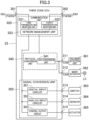
- Fig. 2 is a diagram illustrating a functional configuration example of the first zone ECU 21.
- the first zone ECU 21 includes a communication unit 120, a protocol conversion unit 140, and a signal conversion unit 150.
- the protocol conversion unit 140 includes a CAN conversion unit 141 and a LIN conversion unit 142.
- the signal conversion unit 150 includes a digital input circuit 151, an analog input circuit 152, and control output circuits 153 and 154.
- the first zone ECU 21 includes, as communication ports (hereinafter, referred to as "trunk ports") connected to the trunk network, a trunk port 101 to which the Ethernet cable EB1 is connected and a trunk port 102 to which the CAN-FD cable CB5 is connected.
- the trunk port 101 and the trunk port 102 are ports to which a trunk network signal that is a signal transmitted on the trunk network is input and output.
- the first zone ECU 21 includes communication ports 111 to 118 as communication ports connected to the device-side network.
- the first zone ECU 21 inputs and outputs CAN signals via the communication ports 111 to 113, inputs and outputs LIN signals via the communication port 114, inputs digital control signals via the communication port 115, inputs analog control signals via the communication port 116, and outputs analog control signals via the communication ports 117 and 118.
- the communication port 111 is connected to a smart ECU 161
- the smart ECU 161 is connected to an airbag device D11.
- the communication port 112 is connected to a smart actuator 162 for locking and unlocking a side door.
- the communication port 113 is connected to a smart actuator 163 for emitting a buzzer sound or the like.
- the communication port 114 is connected to a sensor 164 (hereinafter, referred to as "keyless sensor 164") for operating a keyless device.
- the communication port 115 is connected to a switch 165 (for example, a clutch cut switch, a brake switch, or the like).
- the communication port 116 is connected to a sensor 166 (for example, an accelerator pedal sensor, a clutch stroke sensor, or the like).
- the communication port 117 is connected to a left-side turn light L1 provided on a door mirror on the left side of the vehicle.
- the communication port 118 is connected to an actuator 168 (for example, an indicator lamp or the like attached to a horn, a keyless buzzer, a meter device, or the like).
- an actuator 168 for example, an indicator lamp or the like attached to a horn, a keyless buzzer, a meter device, or the like.
- the symbol mark of a lock mechanism is illustrated in addition to the smart actuator 162 for easy understanding of the description.
- the symbol mark of a sound source mechanism is illustrated.
- the in-vehicle device can be attached or detached by inserting a connector at the distal end of a cable extending from the in-vehicle device into each of the communication ports 111 to 118.
- each of the communication ports 111 to 118 can be connected to a smart connector (not illustrated), and the in-vehicle device can be attached to the smart connector.
- the smart connector SC includes, for example, an analog/digital conversion circuit, a driver circuit, and the like, and has a function of transmitting a drive signal to an actuator serving as the in-vehicle device, and/or a function of transmitting an input signal from a sensor serving as the in-vehicle device to the zone ECU 2.
- the communication unit 120 includes a first transmission and reception unit 121 connected to the trunk port 101, a second transmission and reception unit 122 connected to the trunk port 102, and a network management unit 123.
- the first transmission and reception unit 121 has a function of transmitting and receiving a trunk network signal (an Ethernet signal) to and from the central processing unit 10 via the trunk port 101 and the Ethernet cable EB1.
- a trunk network signal an Ethernet signal
- the first transmission and reception unit 121 includes, for example, a coding circuit that generates an Ethernet signal, a driver circuit that outputs the Ethernet signal generated by the coding circuit to the central processing unit 10, a receiver circuit that receives the Ethernet signal output from the central processing unit 10, and a decoding circuit that decodes the Ethernet signal received by the receiver circuit.
- the second transmission and reception unit 122 has a function of transmitting and receiving a trunk network signal (a CAN-FD signal) to and from the fifth zone ECU 25 via the trunk port 102 and the CAN-FD cable CB5.
- the second transmission and reception unit 122 includes, for example, a coding circuit that generates a CAN-FD signal, a driver circuit that outputs the CAN-FD signal generated by the coding circuit to the fifth zone ECU 25, a receiver circuit that receives the CAN-FD signal output from the fifth zone ECU 25, and a decoding circuit that decodes the CAN-FD signal received by the receiver circuit.
- the network management unit 123 has (a) a relay function of relaying a trunk network signal on a trunk network, that is, between the trunk ports 101 and 102, (b) a distribution function of extracting a signal for a device connected to the own ECU from trunk network signals and distributing the signal, and (c) an integration function of integrating data to be transmitted from the device connected to the own ECU to the central processing unit 10 and/or another zone ECU 2.
- a relay function of relaying a trunk network signal on a trunk network, that is, between the trunk ports 101 and 102
- a distribution function of extracting a signal for a device connected to the own ECU from trunk network signals and distributing the signal
- an integration function of integrating data to be transmitted from the device connected to the own ECU to the central processing unit 10 and/or another zone ECU 2.
- the protocol conversion unit 140 performs protocol conversion so that data can be exchanged between communication schemes. Specifically, the protocol conversion unit 140 is connected to the network management unit 123, and performs protocol conversion according to each of "(a) relay function", “(b) distribution function", and "(c) integration function” of the network management unit 123 described above. Note that, in the present embodiment, the protocol conversion includes a conversion process such as data length conversion between CAN and CAN-FD.
- the network management unit 123 extracts data (hereinafter, referred to as "relay data”) to be transmitted to the fifth zone ECU 25 from the Ethernet signal input from the central processing unit 10, and outputs the extracted data to the protocol conversion unit 140.
- the protocol conversion unit 140 converts relay data to CAN protocol data and outputs the CAN protocol data to the network management unit 123.
- the network management unit 123 generates a CAN signal on the basis of the CAN protocol data.
- the second transmission and reception unit 122 then outputs the CAN signal to the fifth zone ECU 25 via the trunk port 102.
- the network management unit 123 extracts data (hereinafter, referred to as "own ECU data") for a device connected to the own ECU from the Ethernet signal input from the central processing unit 10.
- the network management unit 123 determines whether the data for the own ECU is data for a device connected to the protocol conversion unit 140 or data for a device connected to the signal conversion unit 150, and distributes the data to each of the units.
- the protocol conversion unit 140 when data for devices connected to the communication ports 111 to 113 is received from the network management unit 123, the CAN conversion unit 141 converts the received data to a signal conforming to the CAN protocol and outputs the signal to the communication ports 111 to 113.
- the control output circuit 154 when data for controlling the actuator 168 connected to the communication port 118 is received from the network management unit 123, the control output circuit 154 generates, for example, an analog control signal of the actuator 168 according to a control value received from the central processing unit 10, and outputs the analog control signal to the communication port 118. Note that, the process similar to that in the case of the central processing unit 10 described above is also performed in a case where data for a device connected to the own ECU is included in the CAN signal input from the fifth zone ECU 25.
- the protocol conversion unit 140 receives an unlock signal (a LIN signal) from the keyless sensor 164, converts data conforming to the LIN protocol to data conforming to the Ethernet protocol, and transmits the converted data to the network management unit 123.
- the digital input circuit 151 receives an input signal from the switch 165
- the analog input circuit 152 receives an input signal from the sensor 166
- the circuits 151 and 152 transmit the received data to the network management unit 123.
- the network management unit 123 integrates the received data from the protocol conversion unit 140 and the received data from the signal conversion unit 150.
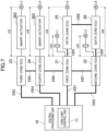
- the third zone ECU 23 includes communication ports 311 to 315 as device ports.
- the third zone ECU 23 inputs and outputs CAN signals via the communication ports 311 and 312, inputs digital control signals via the communication port 313, inputs analog control signals via the communication port 314, and outputs analog control signals via the communication port 315.
- the communication port 311 is connected to a collision detection unit 361 that detects a collision of the vehicle 1.
- the communication port 312 is connected to a smart actuator 362 for operating a left-front turn light L3 on the left side of the vehicle.
- the communication port 313 is connected to a switch 363 (for example, a washer level switch, a hood switch, or the like).
- the communication port 314 is connected to a sensor 364 (for example, an outside air temperature sensor, an air flow sensor, or the like).
- the communication port 315 is connected to an actuator 365 (for example, a horn, a keyless buzzer, or the like).
- the communication unit 320 includes a third transmission and reception unit 321 connected to the trunk port 301, a fourth transmission and reception unit 322 connected to the trunk port 302, and a network management unit 323.
- the configuration and function related to the invention of the present application are similar to those of the communication unit 120 of the first zone ECU 21 described above, and thus the detailed description thereof will be omitted here.
- the difference is that the second transmission and reception unit 122 conforms to the CAN-FD protocol in the first zone ECU 21, whereas the fourth transmission and reception unit 322 conforms to the Ethernet protocol in the third zone ECU 23.
- the configuration of the transmission and reception circuit and the delay information conforming to each communication scheme can be replaced on the basis of the conventional technique.
- the protocol conversion unit 340 performs protocol conversion so that data can be exchanged between communication schemes.
- the difference between the protocol conversion unit 340 and the protocol conversion unit 140 of the first zone ECU 21 will be mainly described, and the description of the same contents may be omitted.
- the third zone ECU 23 relays between an Ethernet signal and an Ethernet signal in "(a) relay function". Consequently, unlike the protocol conversion unit 140 described above, the protocol conversion unit 340 does not require protocol conversion in the relay process.
- "(b) Distribution function” and "(c) integration function" in the third zone ECU 23 have the same contents as those in the first zone ECU 21 described above, and thus the detailed description thereof will be omitted here.
- the fourth zone ECU 24 has the same configuration as the third zone ECU 23, and the same reference signs are given to in-vehicle devices connected to the respective zone ECUs 23 and 24.
- the detailed description of the fourth zone ECU 24 will be omitted.
- the third zone ECU 23 and the fourth zone ECU 24 can have completely different configurations, and/or different in-vehicle devices can be connected to the respective zone ECUs 23 and 24.
- the right-front turn lamp that is provided on the right side of the vehicle and is connected to the fourth zone ECU 24 is distinguished from the left-front turn light L3 connected to the third zone ECU 23, and is denoted by a reference sign L4.
- Fig. 4 illustrates a functional configuration example of the fifth zone ECU 25.
- the description of the same configuration as that of the first zone ECU 21 and/or the third zone ECU 23 may be omitted.
- the fifth zone ECU 25 includes a communication unit 520, a protocol conversion unit 540, and a signal conversion unit 550.
- the protocol conversion unit 540 includes a CAN conversion unit 541 and a LIN conversion unit 542.
- the signal conversion unit 550 includes a digital input circuit 551, an analog input circuit 552, and a control output circuit 553.
- the fifth zone ECU 25 includes a trunk port 501 to which the CAN-FD cable CB5 is connected and a trunk port 502 to which the CAN-FD cable CB8 is connected.
- a CAN-FD signal is input and output to and from the trunk port 501 and the trunk port 502, and the trunk port 501 and the trunk port 502 are directly connected.
- the fifth zone ECU 25 includes communication ports 511 to 516 as device ports.
- the fifth zone ECU 25 inputs and outputs CAN signals via the communication ports 511 and 512, inputs and outputs LIN signals via the communication port 513, inputs digital control signals via the communication port 514, inputs analog control signals via the communication port 515, and outputs analog control signals via the communication port 516.
- the communication port 511 is connected to a smart actuator 561 for emitting a buzzer sound or the like.
- the communication port 512 is connected to a smart actuator 562 for locking a side door.
- the communication port 513 is connected to a back sonar device 563.
- the communication port 514 is connected to a switch 564.
- the communication port 515 is connected to a sensor 565 (for example, a fuel sensor, a kick sensor, or the like).
- the communication port 516 is connected to a left-rear turn light L5 on the left rear of the vehicle.
- the symbol mark of the sound source mechanism is illustrated in addition to the smart actuator 561 for easy understanding of the description.
- the symbol mark of the lock mechanism is illustrated.
- the communication unit 520 includes a transmission and reception unit 521 connected to a common communication line connecting the trunk port 501 and the trunk port 502 and a network management unit 522.
- the transmission and reception unit 521 includes, for example, a coding circuit that generates a CAN-FD signal, a driver circuit and a receiver circuit connected to the common communication line, and a decoding circuit that decodes the CAN-FD signal received by the receiver circuit.
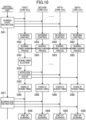
- step S61 of Fig. 6 the central processing unit 10 transmits a blinking start instruction to the zone ECUs 21 to 26 as a blinking control signal.
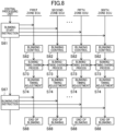
- step S61 of Fig. 8 as in the case of Fig. 6 , the central processing unit 10 transmits a blinking start instruction to each zone ECU 2 as a blinking control signal.
- step S62 when receiving the blinking start instruction from the central processing unit 10, the zone ECUs 2 execute blinking control of the turn lights L1 to L6 connected to themselves.
- each zone ECU 2 performs a blinking-timing information sharing process of sharing blinking timing information of the turn light L controlled by each ECU 2.
- the blinking timing information can be shared with each other without the central processing unit 10 interposed therebetween, or the blinking timing information can be shared with each other with the central processing unit 10 interposed as a hub device.
- the zone ECUs 2 compare the blinking timing of the turn light L of another zone ECU 2 with the blinking timing of the turn light L of the own ECU 2, and perform an adjustment process of adjusting the blinking timing of the turn light L of the own ECU.
- the method of adjusting the blinking timing is only required to be able to adjust the blinking timing, and a specific method is not particularly limited.
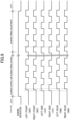
- Fig. 9 illustrates an example of a method of adjusting a blinking timing.
- the blinking timing of the left-side turn light L1 and the blinking timing of the right-side turn light L2 are substantially the same, and their blinking start time is the earliest.
- the left-front turn light L3 and the right-front turn light L4 start blinking substantially simultaneously
- the left-rear turn light L5 and the right-rear turn light L6 start blinking substantially simultaneously.
- step S74 is performed during a "timing adjustment" period in Fig. 9 .
- the zone ECUs 2 compare the blinking timing of the turn light L of another zone ECU 2 with the blinking timing of the turn light L of the own ECU 2, and execute control to advance a turn-off time in accordance with the earliest blinking timing.
- the turn-off times of the respective turn lights L can be the same.
- the pitch of turning on and off the turn light L can be set in advance. Consequently, in a case where the turn-off time is advanced, each zone ECU 2 can repeat turning on and off the turn light L at a predetermined pitch by setting the turn-off time as a starting point.
- the turn-on and turn-off times of the turn lights L can be the same, that is, the blinking timings can match.
- each zone ECU 2 ends blinking of the turn light (step S68).
- timing adjustment is the control to advance the turn-off time in accordance with the earliest blinking timing, but the present invention is not limited thereto.
- the zone ECU or the smart actuator that outputs a blinking control signal at the timing farthest from a reference timing can adjust the output timing to the reference timing.
- the reference timing can be set in advance, or can be obtained by calculation, for example, like an average value of timing information received from each zone ECU.
- each zone ECU 2 outputs a blinking control signal whose blinking timing has been adjusted to the turn light on the basis of the timing adjustment signal received from the master ECU.
- each zone ECU 2 ends blinking of the turn light (step S68).
- the blinking control operation itself is incorporated in the central processing unit 10, but fine timing adjustment is handled on the zone ECU side.
- the technology of the present disclosure can also be applied to the synchronous control of an actuator other than the turn light L.
- the smart actuator for example, see 163, 561 in Fig. 1
- the smart actuator 163 connected to the first zone ECU 21 is an example of a first actuator
- the smart actuator 163 connected to the second ECU 22 is an example of a second actuator.
- the central processing unit 10 then transmits a common timing signal to the first zone ECU 21 and the second zone ECU 22.
- the first zone ECU 21 transmits drive timing information of the smart actuator 163 based on the received timing signal to the central processing unit 10.
- the second zone ECU 22 transmits drive timing information of the smart actuator 163 based on the received timing signal to the central processing unit 10.
- the central processing unit 10 then transmits an adjustment signal in which the timing has been adjusted in accordance with the received drive timing information to the first zone ECU 21 and the second zone ECU 22.
- the technology disclosed herein is useful for designing a vehicle control system.
Landscapes
- Engineering & Computer Science (AREA)
- Mechanical Engineering (AREA)
- Computer Networks & Wireless Communication (AREA)
- Signal Processing (AREA)
- Automation & Control Theory (AREA)
- Small-Scale Networks (AREA)
- Lighting Device Outwards From Vehicle And Optical Signal (AREA)
Claims (2)
- Fahrzeugsteuersystem, umfassend:eine Vielzahl von Zonen-ECUs (2), von denen jede in jeder vorbestimmten Zone eines Fahrzeugs (1) angeordnet ist;eine Zentraleinheit (10), die mit den Zonen-ECUs (2) über ein Trunk-Netzwerk zur Zeitsynchronisation verbunden ist;wobei die Zonen-ECUs (2) aufweisen:eine erste Zonen-ECU (21), die ein erstes Zeitsteuerungssignal zum Betreiben eines ersten Betätigungselements, das in dem Fahrzeug (1) installiert ist, anhand eines Steuersignals ausgibt, das von der Zentraleinheit (10) empfangen wird, undeine zweite Zonen-ECU (22), die ein zweites Zeitsteuerungssignal zum Betreiben eines zweiten Betätigungselements, das an einer anderen Position als einer Position des ersten Betätigungselements des Fahrzeugs (1) installiert ist, anhand eines Steuersignals ausgibt, das von der Zentraleinheit (10) empfangen wird,die Zentraleinheit (10) und die erste Zonen-ECU (21) und die Zentraleinheit (10) und die zweite Zonen-ECU (22) durch ein Zeitsynchronisationsnetzwerk verbunden sind, wobei die erste Zonen-ECU (21) und das erste Betätigungselement und die zweite Zonen-ECU (22) und das zweite Betätigungselement durch ein zeitasynchrones Netzwerk verbunden sind,die Zentraleinheit (10) ein gemeinsames Zeitsteuerungssignal an die erste Zonen-ECU (21) und die zweite Zonen-ECU (22) überträgt,die erste Zonen-ECU (21) Antriebszeitsteuerungsinformationen des ersten Betätigungselements anhand des Zeitsteuerungssignals an die Zentraleinheit (10) überträgt, und die zweite Zonen-ECU (22) Antriebszeitsteuerungsinformationen des zweiten Betätigungselements anhand des Zeitsteuerungssignals an die Zentraleinheit (10) überträgt, unddie Zentraleinheit (10) so konfiguriert ist, dass sie ein Einstellsignal zum Einstellen der Zeitsteuerung der Betätigungselemente in Übereinstimmung mit den Antriebszeitsteuerungsinformationen der ersten und zweiten Betätigungselemente an die erste Zonen-ECU (21) und die zweite Zonen-ECU (22) überträgt, so dassdas erste Betätigungselement und das zweite Betätigungselement synchronisiert betrieben werden.
- Fahrzeugsteuersystem nach Anspruch 1, wobei das Betätigungselement ein Blinker ist.
Applications Claiming Priority (2)
| Application Number | Priority Date | Filing Date | Title |
|---|---|---|---|
| JP2019141111A JP7298371B2 (ja) | 2019-07-31 | 2019-07-31 | 車両制御システム |
| PCT/JP2020/028098 WO2021020211A1 (ja) | 2019-07-31 | 2020-07-20 | 車両制御システム |
Publications (3)
| Publication Number | Publication Date |
|---|---|
| EP4005871A1 EP4005871A1 (de) | 2022-06-01 |
| EP4005871A4 EP4005871A4 (de) | 2022-09-14 |
| EP4005871B1 true EP4005871B1 (de) | 2025-07-02 |
Family
ID=74230258
Family Applications (1)
| Application Number | Title | Priority Date | Filing Date |
|---|---|---|---|
| EP20847517.8A Active EP4005871B1 (de) | 2019-07-31 | 2020-07-20 | Fahrzeugsteuerungssystem |
Country Status (5)
| Country | Link |
|---|---|
| US (1) | US20220274523A1 (de) |
| EP (1) | EP4005871B1 (de) |
| JP (1) | JP7298371B2 (de) |
| CN (1) | CN114174125B (de) |
| WO (1) | WO2021020211A1 (de) |
Families Citing this family (6)
| Publication number | Priority date | Publication date | Assignee | Title |
|---|---|---|---|---|
| DE102021104421A1 (de) * | 2021-02-24 | 2022-08-25 | Robert Bosch Gesellschaft mit beschränkter Haftung | Verfahren zum Betreiben eines Bordnetzes, Bordnetz, und Rechensystem |
| EP4098499B1 (de) | 2021-05-31 | 2026-01-07 | Aptiv Technologies AG | Raddrehzahlmesssystem |
| JP7410085B2 (ja) * | 2021-06-11 | 2024-01-09 | 矢崎総業株式会社 | 通信システム及び上位制御装置 |
| CN114755965B (zh) * | 2022-04-24 | 2024-11-05 | 重庆长安汽车股份有限公司 | 一种仪表报警灯闪烁同步的方法、电子设备及存储介质 |
| CN115048154B (zh) * | 2022-07-06 | 2024-05-03 | 北斗星通智联科技有限责任公司 | 车载配置信息管理方法、装置、系统及存储介质 |
| CN118645001A (zh) * | 2024-08-15 | 2024-09-13 | 成都工业职业技术学院 | 基于人员流动数据的公交线路站点配置方法及系统 |
Family Cites Families (21)
| Publication number | Priority date | Publication date | Assignee | Title |
|---|---|---|---|---|
| JP3494833B2 (ja) * | 1996-12-19 | 2004-02-09 | 矢崎総業株式会社 | ハザード表示装置 |
| JP2001138804A (ja) * | 1999-11-11 | 2001-05-22 | Yazaki Corp | 車載通信ネットワークにおけるランプ負荷の点滅制御方法ならびにそのシステム |
| JP2004291880A (ja) * | 2003-03-27 | 2004-10-21 | Sumitomo Electric Ind Ltd | 車載通信システム及び中継装置 |
| JP4196838B2 (ja) * | 2004-01-15 | 2008-12-17 | 株式会社デンソー | 車載システム |
| DE102004022555B4 (de) * | 2004-05-07 | 2006-04-06 | Siemens Ag | Vorrichtung und Verfahren zum Synchronisieren einer Blinkerfrequenz mit einer Zentralblinkfrequenz |
| JP4324795B2 (ja) * | 2004-12-10 | 2009-09-02 | 三菱自動車工業株式会社 | 車載制御装置 |
| JP5359507B2 (ja) * | 2009-04-20 | 2013-12-04 | 株式会社オートネットワーク技術研究所 | 入出力装置及び制御システム |
| US8504864B2 (en) * | 2010-12-01 | 2013-08-06 | GM Global Technology Operations LLC | Data sensor coordination using time synchronization in a multi-bus controller area network system |
| US8775681B2 (en) * | 2011-04-27 | 2014-07-08 | GM Global Technology Operations LLC | Cross-network synchronization of application S/W execution using flexray global time |
| JP5648612B2 (ja) * | 2011-09-11 | 2015-01-07 | 株式会社デンソー | 車載機器制御システム |
| DE102012204586B4 (de) * | 2012-03-22 | 2025-02-27 | Bayerische Motoren Werke Aktiengesellschaft | Gateway, Knoten und Verfahren für ein Fahrzeug |
| KR102314611B1 (ko) * | 2015-09-23 | 2021-10-18 | 삼성전자주식회사 | 양방향 동기가 가능한 카메라, 상기 카메라를 포함하는 카메라 시스템 및 그 동작 방법 |
| JP6485306B2 (ja) * | 2015-09-25 | 2019-03-20 | 株式会社デンソー | 制御システム |
| WO2017196981A1 (en) * | 2016-05-10 | 2017-11-16 | Robert Bosch Llc | Clutch and shift automatic manual transmission (amt) device for a drive system |
| JP6962697B2 (ja) | 2016-05-27 | 2021-11-05 | パナソニック インテレクチュアル プロパティ コーポレーション オブ アメリカPanasonic Intellectual Property Corporation of America | ネットワークハブ、転送方法及び車載ネットワークシステム |
| US20180062988A1 (en) * | 2016-08-31 | 2018-03-01 | Faraday&Future Inc. | Ethernet communication of can signals |
| JP6443831B1 (ja) * | 2017-10-30 | 2018-12-26 | マツダ株式会社 | 車両用ランプ装置 |
| JP6443830B1 (ja) * | 2017-10-30 | 2018-12-26 | マツダ株式会社 | 車両用ランプ装置 |
| EP3861701A1 (de) * | 2018-10-05 | 2021-08-11 | Google LLC | Synchrone klänge für audioassistent auf vorrichtungen |
| CN109547313B (zh) * | 2018-12-07 | 2021-12-14 | 北京汽车集团有限公司 | 网络状态管理方法和装置 |
| JP7434728B2 (ja) | 2019-06-13 | 2024-02-21 | マツダ株式会社 | 車載ネットワークシステム |
-
2019
- 2019-07-31 JP JP2019141111A patent/JP7298371B2/ja active Active
-
2020
- 2020-07-20 WO PCT/JP2020/028098 patent/WO2021020211A1/ja not_active Ceased
- 2020-07-20 US US17/631,499 patent/US20220274523A1/en not_active Abandoned
- 2020-07-20 CN CN202080054664.XA patent/CN114174125B/zh active Active
- 2020-07-20 EP EP20847517.8A patent/EP4005871B1/de active Active
Also Published As
| Publication number | Publication date |
|---|---|
| WO2021020211A1 (ja) | 2021-02-04 |
| US20220274523A1 (en) | 2022-09-01 |
| JP7298371B2 (ja) | 2023-06-27 |
| JP2021024315A (ja) | 2021-02-22 |
| EP4005871A4 (de) | 2022-09-14 |
| EP4005871A1 (de) | 2022-06-01 |
| CN114174125B (zh) | 2023-08-25 |
| CN114174125A (zh) | 2022-03-11 |
Similar Documents
| Publication | Publication Date | Title |
|---|---|---|
| EP4005871A1 (de) | Fahrzeugsteuerungssystem | |
| EP4007216B1 (de) | Fahrzeugsteuerungssystem und verfahren zur entwicklung eines fahrzeugsteuerungssystems | |
| EP4007217B1 (de) | Fahrzeugsteuerungssystem und entwurfsverfahren für ein fahrzeugsteuerungssystem | |
| EP4001011B1 (de) | Fahrzeugsteuerungssystem | |
| EP3998748B1 (de) | Fahrzeugbordnetzsystem | |
| US20200125858A1 (en) | Power and Data Center (PDC) for Automotive Applications | |
| JP7408939B2 (ja) | ネットワークハブ装置 | |
| EP3998745B1 (de) | Netzwerk-hub-vorrichtung |
Legal Events
| Date | Code | Title | Description |
|---|---|---|---|
| STAA | Information on the status of an ep patent application or granted ep patent |
Free format text: STATUS: THE INTERNATIONAL PUBLICATION HAS BEEN MADE |
|
| PUAI | Public reference made under article 153(3) epc to a published international application that has entered the european phase |
Free format text: ORIGINAL CODE: 0009012 |
|
| STAA | Information on the status of an ep patent application or granted ep patent |
Free format text: STATUS: REQUEST FOR EXAMINATION WAS MADE |
|
| 17P | Request for examination filed |
Effective date: 20220223 |
|
| AK | Designated contracting states |
Kind code of ref document: A1 Designated state(s): AL AT BE BG CH CY CZ DE DK EE ES FI FR GB GR HR HU IE IS IT LI LT LU LV MC MK MT NL NO PL PT RO RS SE SI SK SM TR |
|
| REG | Reference to a national code |
Ref country code: DE Ref legal event code: R079 Free format text: PREVIOUS MAIN CLASS: B60Q0001340000 Ipc: H04L0012403000 Ref document number: 602020053958 Country of ref document: DE |
|
| A4 | Supplementary search report drawn up and despatched |
Effective date: 20220816 |
|
| RIC1 | Information provided on ipc code assigned before grant |
Ipc: H04L 12/413 20060101ALI20220809BHEP Ipc: H04L 12/403 20060101AFI20220809BHEP |
|
| DAV | Request for validation of the european patent (deleted) | ||
| DAX | Request for extension of the european patent (deleted) | ||
| STAA | Information on the status of an ep patent application or granted ep patent |
Free format text: STATUS: EXAMINATION IS IN PROGRESS |
|
| 17Q | First examination report despatched |
Effective date: 20240126 |
|
| GRAP | Despatch of communication of intention to grant a patent |
Free format text: ORIGINAL CODE: EPIDOSNIGR1 |
|
| STAA | Information on the status of an ep patent application or granted ep patent |
Free format text: STATUS: GRANT OF PATENT IS INTENDED |
|
| INTG | Intention to grant announced |
Effective date: 20250404 |
|
| RIC1 | Information provided on ipc code assigned before grant |
Ipc: H04L 12/403 20060101AFI20250328BHEP |
|
| GRAS | Grant fee paid |
Free format text: ORIGINAL CODE: EPIDOSNIGR3 |
|
| GRAA | (expected) grant |
Free format text: ORIGINAL CODE: 0009210 |
|
| STAA | Information on the status of an ep patent application or granted ep patent |
Free format text: STATUS: THE PATENT HAS BEEN GRANTED |
|
| AK | Designated contracting states |
Kind code of ref document: B1 Designated state(s): AL AT BE BG CH CY CZ DE DK EE ES FI FR GB GR HR HU IE IS IT LI LT LU LV MC MK MT NL NO PL PT RO RS SE SI SK SM TR |
|
| REG | Reference to a national code |
Ref country code: GB Ref legal event code: FG4D |
|
| REG | Reference to a national code |
Ref country code: CH Ref legal event code: EP |
|
| REG | Reference to a national code |
Ref country code: DE Ref legal event code: R096 Ref document number: 602020053958 Country of ref document: DE |
|
| REG | Reference to a national code |
Ref country code: IE Ref legal event code: FG4D |
|
| PGFP | Annual fee paid to national office [announced via postgrant information from national office to epo] |
Ref country code: DE Payment date: 20250813 Year of fee payment: 6 |
|
| REG | Reference to a national code |
Ref country code: NL Ref legal event code: MP Effective date: 20250702 |
|
| PG25 | Lapsed in a contracting state [announced via postgrant information from national office to epo] |
Ref country code: PT Free format text: LAPSE BECAUSE OF FAILURE TO SUBMIT A TRANSLATION OF THE DESCRIPTION OR TO PAY THE FEE WITHIN THE PRESCRIBED TIME-LIMIT Effective date: 20251103 |
|
| PG25 | Lapsed in a contracting state [announced via postgrant information from national office to epo] |
Ref country code: NL Free format text: LAPSE BECAUSE OF FAILURE TO SUBMIT A TRANSLATION OF THE DESCRIPTION OR TO PAY THE FEE WITHIN THE PRESCRIBED TIME-LIMIT Effective date: 20250702 |
|
| REG | Reference to a national code |
Ref country code: AT Ref legal event code: MK05 Ref document number: 1810558 Country of ref document: AT Kind code of ref document: T Effective date: 20250702 |
|
| PG25 | Lapsed in a contracting state [announced via postgrant information from national office to epo] |
Ref country code: IS Free format text: LAPSE BECAUSE OF FAILURE TO SUBMIT A TRANSLATION OF THE DESCRIPTION OR TO PAY THE FEE WITHIN THE PRESCRIBED TIME-LIMIT Effective date: 20251102 |
|
| PG25 | Lapsed in a contracting state [announced via postgrant information from national office to epo] |
Ref country code: NO Free format text: LAPSE BECAUSE OF FAILURE TO SUBMIT A TRANSLATION OF THE DESCRIPTION OR TO PAY THE FEE WITHIN THE PRESCRIBED TIME-LIMIT Effective date: 20251002 |
|
| REG | Reference to a national code |
Ref country code: LT Ref legal event code: MG9D |
|
| PG25 | Lapsed in a contracting state [announced via postgrant information from national office to epo] |
Ref country code: AT Free format text: LAPSE BECAUSE OF FAILURE TO SUBMIT A TRANSLATION OF THE DESCRIPTION OR TO PAY THE FEE WITHIN THE PRESCRIBED TIME-LIMIT Effective date: 20250702 |
|
| PG25 | Lapsed in a contracting state [announced via postgrant information from national office to epo] |
Ref country code: FI Free format text: LAPSE BECAUSE OF FAILURE TO SUBMIT A TRANSLATION OF THE DESCRIPTION OR TO PAY THE FEE WITHIN THE PRESCRIBED TIME-LIMIT Effective date: 20250702 |
|
| PG25 | Lapsed in a contracting state [announced via postgrant information from national office to epo] |
Ref country code: HR Free format text: LAPSE BECAUSE OF FAILURE TO SUBMIT A TRANSLATION OF THE DESCRIPTION OR TO PAY THE FEE WITHIN THE PRESCRIBED TIME-LIMIT Effective date: 20250702 |
|
| PG25 | Lapsed in a contracting state [announced via postgrant information from national office to epo] |
Ref country code: GR Free format text: LAPSE BECAUSE OF FAILURE TO SUBMIT A TRANSLATION OF THE DESCRIPTION OR TO PAY THE FEE WITHIN THE PRESCRIBED TIME-LIMIT Effective date: 20251003 |
|
| PG25 | Lapsed in a contracting state [announced via postgrant information from national office to epo] |
Ref country code: SE Free format text: LAPSE BECAUSE OF FAILURE TO SUBMIT A TRANSLATION OF THE DESCRIPTION OR TO PAY THE FEE WITHIN THE PRESCRIBED TIME-LIMIT Effective date: 20250702 Ref country code: CZ Free format text: LAPSE BECAUSE OF FAILURE TO SUBMIT A TRANSLATION OF THE DESCRIPTION OR TO PAY THE FEE WITHIN THE PRESCRIBED TIME-LIMIT Effective date: 20250702 |
|
| PG25 | Lapsed in a contracting state [announced via postgrant information from national office to epo] |
Ref country code: LV Free format text: LAPSE BECAUSE OF FAILURE TO SUBMIT A TRANSLATION OF THE DESCRIPTION OR TO PAY THE FEE WITHIN THE PRESCRIBED TIME-LIMIT Effective date: 20250702 |
|
| PG25 | Lapsed in a contracting state [announced via postgrant information from national office to epo] |
Ref country code: BG Free format text: LAPSE BECAUSE OF FAILURE TO SUBMIT A TRANSLATION OF THE DESCRIPTION OR TO PAY THE FEE WITHIN THE PRESCRIBED TIME-LIMIT Effective date: 20250702 Ref country code: PL Free format text: LAPSE BECAUSE OF FAILURE TO SUBMIT A TRANSLATION OF THE DESCRIPTION OR TO PAY THE FEE WITHIN THE PRESCRIBED TIME-LIMIT Effective date: 20250702 |
|
| PG25 | Lapsed in a contracting state [announced via postgrant information from national office to epo] |
Ref country code: RS Free format text: LAPSE BECAUSE OF FAILURE TO SUBMIT A TRANSLATION OF THE DESCRIPTION OR TO PAY THE FEE WITHIN THE PRESCRIBED TIME-LIMIT Effective date: 20251002 |
|
| PG25 | Lapsed in a contracting state [announced via postgrant information from national office to epo] |
Ref country code: ES Free format text: LAPSE BECAUSE OF FAILURE TO SUBMIT A TRANSLATION OF THE DESCRIPTION OR TO PAY THE FEE WITHIN THE PRESCRIBED TIME-LIMIT Effective date: 20250702 |
|
| REG | Reference to a national code |
Ref country code: CH Ref legal event code: H13 Free format text: ST27 STATUS EVENT CODE: U-0-0-H10-H13 (AS PROVIDED BY THE NATIONAL OFFICE) Effective date: 20260224 |
|
| PG25 | Lapsed in a contracting state [announced via postgrant information from national office to epo] |
Ref country code: RO Free format text: LAPSE BECAUSE OF FAILURE TO SUBMIT A TRANSLATION OF THE DESCRIPTION OR TO PAY THE FEE WITHIN THE PRESCRIBED TIME-LIMIT Effective date: 20250702 Ref country code: LU Free format text: LAPSE BECAUSE OF NON-PAYMENT OF DUE FEES Effective date: 20250720 |
|
| REG | Reference to a national code |
Ref country code: BE Ref legal event code: MM Effective date: 20250731 |
|
| PG25 | Lapsed in a contracting state [announced via postgrant information from national office to epo] |
Ref country code: SM Free format text: LAPSE BECAUSE OF FAILURE TO SUBMIT A TRANSLATION OF THE DESCRIPTION OR TO PAY THE FEE WITHIN THE PRESCRIBED TIME-LIMIT Effective date: 20250702 |
|
| PG25 | Lapsed in a contracting state [announced via postgrant information from national office to epo] |
Ref country code: DK Free format text: LAPSE BECAUSE OF FAILURE TO SUBMIT A TRANSLATION OF THE DESCRIPTION OR TO PAY THE FEE WITHIN THE PRESCRIBED TIME-LIMIT Effective date: 20250702 |
|
| PG25 | Lapsed in a contracting state [announced via postgrant information from national office to epo] |
Ref country code: BE Free format text: LAPSE BECAUSE OF NON-PAYMENT OF DUE FEES Effective date: 20250731 Ref country code: IT Free format text: LAPSE BECAUSE OF FAILURE TO SUBMIT A TRANSLATION OF THE DESCRIPTION OR TO PAY THE FEE WITHIN THE PRESCRIBED TIME-LIMIT Effective date: 20250702 |
|
| PG25 | Lapsed in a contracting state [announced via postgrant information from national office to epo] |
Ref country code: CH Free format text: LAPSE BECAUSE OF NON-PAYMENT OF DUE FEES Effective date: 20250731 |
|
| PG25 | Lapsed in a contracting state [announced via postgrant information from national office to epo] |
Ref country code: EE Free format text: LAPSE BECAUSE OF FAILURE TO SUBMIT A TRANSLATION OF THE DESCRIPTION OR TO PAY THE FEE WITHIN THE PRESCRIBED TIME-LIMIT Effective date: 20250702 Ref country code: SK Free format text: LAPSE BECAUSE OF FAILURE TO SUBMIT A TRANSLATION OF THE DESCRIPTION OR TO PAY THE FEE WITHIN THE PRESCRIBED TIME-LIMIT Effective date: 20250702 |
|
| PLBE | No opposition filed within time limit |
Free format text: ORIGINAL CODE: 0009261 |
|
| STAA | Information on the status of an ep patent application or granted ep patent |
Free format text: STATUS: NO OPPOSITION FILED WITHIN TIME LIMIT |