EP4005878A1 - Système d'alimentation électrique monté dans un véhicule - Google Patents
Système d'alimentation électrique monté dans un véhicule Download PDFInfo
- Publication number
- EP4005878A1 EP4005878A1 EP20846293.7A EP20846293A EP4005878A1 EP 4005878 A1 EP4005878 A1 EP 4005878A1 EP 20846293 A EP20846293 A EP 20846293A EP 4005878 A1 EP4005878 A1 EP 4005878A1
- Authority
- EP
- European Patent Office
- Prior art keywords
- power
- storage device
- power storage
- supply system
- voltage
- Prior art date
- Legal status (The legal status is an assumption and is not a legal conclusion. Google has not performed a legal analysis and makes no representation as to the accuracy of the status listed.)
- Pending
Links
Images


Classifications
-
- B—PERFORMING OPERATIONS; TRANSPORTING
- B60—VEHICLES IN GENERAL
- B60R—VEHICLES, VEHICLE FITTINGS, OR VEHICLE PARTS, NOT OTHERWISE PROVIDED FOR
- B60R16/00—Electric or fluid circuits specially adapted for vehicles and not otherwise provided for; Arrangement of elements of electric or fluid circuits specially adapted for vehicles and not otherwise provided for
- B60R16/02—Electric or fluid circuits specially adapted for vehicles and not otherwise provided for; Arrangement of elements of electric or fluid circuits specially adapted for vehicles and not otherwise provided for electric constitutive elements
- B60R16/03—Electric or fluid circuits specially adapted for vehicles and not otherwise provided for; Arrangement of elements of electric or fluid circuits specially adapted for vehicles and not otherwise provided for electric constitutive elements for supply of electrical power to vehicle subsystems or for
-
- B—PERFORMING OPERATIONS; TRANSPORTING
- B60—VEHICLES IN GENERAL
- B60R—VEHICLES, VEHICLE FITTINGS, OR VEHICLE PARTS, NOT OTHERWISE PROVIDED FOR
- B60R16/00—Electric or fluid circuits specially adapted for vehicles and not otherwise provided for; Arrangement of elements of electric or fluid circuits specially adapted for vehicles and not otherwise provided for
- B60R16/02—Electric or fluid circuits specially adapted for vehicles and not otherwise provided for; Arrangement of elements of electric or fluid circuits specially adapted for vehicles and not otherwise provided for electric constitutive elements
- B60R16/03—Electric or fluid circuits specially adapted for vehicles and not otherwise provided for; Arrangement of elements of electric or fluid circuits specially adapted for vehicles and not otherwise provided for electric constitutive elements for supply of electrical power to vehicle subsystems or for
- B60R16/0315—Electric or fluid circuits specially adapted for vehicles and not otherwise provided for; Arrangement of elements of electric or fluid circuits specially adapted for vehicles and not otherwise provided for electric constitutive elements for supply of electrical power to vehicle subsystems or for using multiplexing techniques
-
- B—PERFORMING OPERATIONS; TRANSPORTING
- B60—VEHICLES IN GENERAL
- B60R—VEHICLES, VEHICLE FITTINGS, OR VEHICLE PARTS, NOT OTHERWISE PROVIDED FOR
- B60R16/00—Electric or fluid circuits specially adapted for vehicles and not otherwise provided for; Arrangement of elements of electric or fluid circuits specially adapted for vehicles and not otherwise provided for
- B60R16/02—Electric or fluid circuits specially adapted for vehicles and not otherwise provided for; Arrangement of elements of electric or fluid circuits specially adapted for vehicles and not otherwise provided for electric constitutive elements
- B60R16/03—Electric or fluid circuits specially adapted for vehicles and not otherwise provided for; Arrangement of elements of electric or fluid circuits specially adapted for vehicles and not otherwise provided for electric constitutive elements for supply of electrical power to vehicle subsystems or for
- B60R16/033—Electric or fluid circuits specially adapted for vehicles and not otherwise provided for; Arrangement of elements of electric or fluid circuits specially adapted for vehicles and not otherwise provided for electric constitutive elements for supply of electrical power to vehicle subsystems or for characterised by the use of electrical cells or batteries
-
- H—ELECTRICITY
- H02—GENERATION; CONVERSION OR DISTRIBUTION OF ELECTRIC POWER
- H02J—ELECTRIC POWER NETWORKS; CIRCUIT ARRANGEMENTS OR SYSTEMS FOR SUPPLYING OR DISTRIBUTING ELECTRIC POWER; SYSTEMS FOR STORING ELECTRIC ENERGY
- H02J7/00—Circuit arrangements for charging or discharging batteries or for supplying loads from batteries
-
- H—ELECTRICITY
- H02—GENERATION; CONVERSION OR DISTRIBUTION OF ELECTRIC POWER
- H02J—ELECTRIC POWER NETWORKS; CIRCUIT ARRANGEMENTS OR SYSTEMS FOR SUPPLYING OR DISTRIBUTING ELECTRIC POWER; SYSTEMS FOR STORING ELECTRIC ENERGY
- H02J7/00—Circuit arrangements for charging or discharging batteries or for supplying loads from batteries
- H02J7/14—Circuit arrangements for charging or discharging batteries or for supplying loads from batteries for charging batteries from dynamo-electric generators driven at varying speed, e.g. on vehicle
- H02J7/1423—Circuit arrangements for charging or discharging batteries or for supplying loads from batteries for charging batteries from dynamo-electric generators driven at varying speed, e.g. on vehicle with multiple batteries
-
- H—ELECTRICITY
- H02—GENERATION; CONVERSION OR DISTRIBUTION OF ELECTRIC POWER
- H02J—ELECTRIC POWER NETWORKS; CIRCUIT ARRANGEMENTS OR SYSTEMS FOR SUPPLYING OR DISTRIBUTING ELECTRIC POWER; SYSTEMS FOR STORING ELECTRIC ENERGY
- H02J7/00—Circuit arrangements for charging or discharging batteries or for supplying loads from batteries
- H02J7/14—Circuit arrangements for charging or discharging batteries or for supplying loads from batteries for charging batteries from dynamo-electric generators driven at varying speed, e.g. on vehicle
- H02J7/16—Regulation of the charging current or voltage by variation of field
-
- H—ELECTRICITY
- H02—GENERATION; CONVERSION OR DISTRIBUTION OF ELECTRIC POWER
- H02J—ELECTRIC POWER NETWORKS; CIRCUIT ARRANGEMENTS OR SYSTEMS FOR SUPPLYING OR DISTRIBUTING ELECTRIC POWER; SYSTEMS FOR STORING ELECTRIC ENERGY
- H02J7/00—Circuit arrangements for charging or discharging batteries or for supplying loads from batteries
- H02J7/34—Parallel operation in networks using both storage and other DC sources, e.g. providing buffering
-
- H—ELECTRICITY
- H02—GENERATION; CONVERSION OR DISTRIBUTION OF ELECTRIC POWER
- H02J—ELECTRIC POWER NETWORKS; CIRCUIT ARRANGEMENTS OR SYSTEMS FOR SUPPLYING OR DISTRIBUTING ELECTRIC POWER; SYSTEMS FOR STORING ELECTRIC ENERGY
- H02J7/00—Circuit arrangements for charging or discharging batteries or for supplying loads from batteries
- H02J7/34—Parallel operation in networks using both storage and other DC sources, e.g. providing buffering
- H02J7/345—Parallel operation in networks using both storage and other DC sources, e.g. providing buffering using capacitors as storage or buffering devices
-
- H—ELECTRICITY
- H02—GENERATION; CONVERSION OR DISTRIBUTION OF ELECTRIC POWER
- H02J—ELECTRIC POWER NETWORKS; CIRCUIT ARRANGEMENTS OR SYSTEMS FOR SUPPLYING OR DISTRIBUTING ELECTRIC POWER; SYSTEMS FOR STORING ELECTRIC ENERGY
- H02J2105/00—Networks for supplying or distributing electric power characterised by their spatial reach or by the load
- H02J2105/30—Networks for supplying or distributing electric power characterised by their spatial reach or by the load the load networks being external to vehicles, i.e. exchanging power with vehicles
- H02J2105/33—Networks for supplying or distributing electric power characterised by their spatial reach or by the load the load networks being external to vehicles, i.e. exchanging power with vehicles exchanging power with road vehicles
-
- H—ELECTRICITY
- H02—GENERATION; CONVERSION OR DISTRIBUTION OF ELECTRIC POWER
- H02J—ELECTRIC POWER NETWORKS; CIRCUIT ARRANGEMENTS OR SYSTEMS FOR SUPPLYING OR DISTRIBUTING ELECTRIC POWER; SYSTEMS FOR STORING ELECTRIC ENERGY
- H02J2105/00—Networks for supplying or distributing electric power characterised by their spatial reach or by the load
- H02J2105/30—Networks for supplying or distributing electric power characterised by their spatial reach or by the load the load networks being external to vehicles, i.e. exchanging power with vehicles
- H02J2105/33—Networks for supplying or distributing electric power characterised by their spatial reach or by the load the load networks being external to vehicles, i.e. exchanging power with vehicles exchanging power with road vehicles
- H02J2105/37—Networks for supplying or distributing electric power characterised by their spatial reach or by the load the load networks being external to vehicles, i.e. exchanging power with vehicles exchanging power with road vehicles exchanging power with electric vehicles [EV] or with hybrid electric vehicles [HEV]
-
- H—ELECTRICITY
- H02—GENERATION; CONVERSION OR DISTRIBUTION OF ELECTRIC POWER
- H02J—ELECTRIC POWER NETWORKS; CIRCUIT ARRANGEMENTS OR SYSTEMS FOR SUPPLYING OR DISTRIBUTING ELECTRIC POWER; SYSTEMS FOR STORING ELECTRIC ENERGY
- H02J7/00—Circuit arrangements for charging or discharging batteries or for supplying loads from batteries
- H02J7/50—Circuit arrangements for charging or discharging batteries or for supplying loads from batteries acting upon multiple batteries simultaneously or sequentially
Definitions
- the present invention relates to a vehicle-mounted power supply system.
- the invention relates to a vehicle-mounted power supply system that includes a power generation device and a power storage device and supplies power with two or more different voltages.
- Vehicle-mountable power storage devices capable of supplying power with a high voltage of 48V or 24V are known in the form of batteries in which a plurality of cells (battery cells) are connected in series.
- Such high-voltage power storage devices mainly supply power to motors that drive vehicles.
- a vehicle equipped with a high-voltage power storage devices is also equipped with a separate power storage device that supplies low-voltage power to components of the vehicle's electrical systems, etc.
- Fig. 5 schematically shows a configuration of a conventionally known power supply system 101.
- the power supply system 101 includes a power storage device 102 that supplies power with a high voltage and a power storage device 103 that supplies low-voltage power to a load 106.
- Each of the power storage devices 102, 103 is powered by a generator 104.
- a DC-DC converter is arranged between the power storage device 102 and the power storage device 103, and the power storage device 103 side is supplied with stepped-down power.
- Patent Document 1 discloses a power supply system including a lithium-ion battery as a high-voltage power storage medium and a lead battery as a low-voltage power storage device.
- Patent Document 1 discloses a technique for appropriately controlling the vehicle power supply even when a sensor abnormality occurs, by means of a switch control section that controls a conduction state and a cut-off state between the lithium-ion battery and the lead battery.
- lead storage batteries are widely used as power storage devices to supply low-voltage power.
- Lead batteries can be produced from cheap materials, and are highly stable power storage devices that can endure discharging of large currents.
- lead since lead is used in the electrodes, the power supply system as a whole tends to become heavier.
- sulfuric acid is used as the electrolyte solution, the danger in case of damage has been pointed out. There is therefore a demand for providing a highly reliable power supply system without using a lead battery.
- Patent Document 1 Japanese Unexamined Patent Application Publication No. 2018-198519
- the present invention was made in view of the aforementioned current situation, and has an object of providing a vehicle-mounted power supply system with high reliability and durability which does not use a lead battery.
- the invention according to Claim 1 relates to a vehicle-mounted power supply system.
- the power supply system according to the present invention includes a primary power storage device having a high-voltage output terminal and a low-voltage output terminal, a secondary power storage device, and a power generation device configured to supply power to the primary power storage device and the secondary power storage device.
- the power supply system according to the present invention further includes a first switch disposed between the power generation device and the primary power storage device, a second switch disposed between the power generation device and the secondary power storage device, and a third switch disposed between the low-voltage output terminal of the primary power storage device and an output terminal of the secondary power storage device.
- the power supply system according to the present invention is characterized in that the power generation device is a power generator provided with an inverter, or a power generator that can output a variable voltage.
- the secondary power storage device is preferably composed of a lithium-ion battery, an electric double-layer capacitor, or an electrolytic capacitor.
- a fourth switch is preferably disposed at the output terminal of the secondary power storage device.
- the primary power storage device has a high-voltage output terminal and a low-voltage output terminal, and, during normal operation, the primary power storage device supplies high-voltage power and low-voltage power. Since it is possible to reduce the occasions for the secondary power storage device to supply power, it is possible to reduce the frequency of replacing the secondary power storage device, and allows for the secondary power storage device to be smaller and have a lower capacity.
- the power supply system turns off the first switch and the second switch to disconnect the primary power storage device, and resumes power supply by means of the power generation device and the secondary power storage device, allowing for stable operation of the vehicle.
- the power supply system according to the present invention eliminates the need to provide a redundancy for the primary power storage device, and allows for the secondary power storage device to be smaller and have a lower capacity, which allows for the vehicle to be made lighter while maintaining reliability of the power supply system as a whole.
- a primary power storage device is a power storage device which supplies power as a main power supply to one or more loads provided to a vehicle.
- the primary power storage device according to the present invention is provided with a high-voltage output terminal and a low-voltage output terminal so that it can supply power with different voltages to various kinds of loads.
- a secondary power storage device is a power storage device that supplies low-voltage power as an auxiliary power supply during normal operation.
- the secondary power storage device is able to cooperate with the power generation device to supply power with different voltages to various loads.
- a power generation device is a device that includes a power generator and supplies power to the loads and the power storage devices.
- the term "power generator” as used here means a motor that generates power using regenerative energy, an alternator that generates power using the vehicle engine as a power source, or other power supply devices for vehicles.
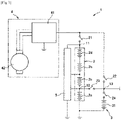
- the power supply system 1 includes a primary power storage device 2, a secondary power storage device 3, and a power generation device 4.
- the difference between the power supply system 1 and the power supply system 61 is the configuration of the secondary power storage device 3.
- the primary power storage device 2 includes a plurality of batteries consisting of a plurality of cells, these batteries being connected in series.
- a plurality of batteries consisting of a plurality of cells, these batteries being connected in series.
- the primary power storage device 2 shown in Fig. 1 and Fig. 2 an embodiment is shown in which four batteries 2a, 2b, 2c, 2d are connected in series.
- the rated voltage of the cells included in the batteries, the number of cells, and the number of batteries to be connected in series in the primary power storage device 2 may be appropriately changed according to the voltage to be supplied.
- Applicable cells for the primary power storage device 2 include lithium-ion cells, nickel-hydride cells, etc.
- the primary power storage device 2 has a high-voltage output terminal 11 and a low-voltage output terminal 12.
- the high-voltage output terminal 11 is able to supply power with the maximum voltage that can be output, by supplying power from all of the batteries 2a, 2b, 2c, 2d.
- the low-voltage output terminal 12 controls the output voltage to be low by supplying power from part of the batteries. In Fig.1 and Fig. 2 , power is supplied from the battery 2a.
- the secondary power storage device 3 may be configured using a single battery 31 including a plurality of cells.
- Preferable applicable cells for the battery 31 include, as in the primary power storage device 2, lithium-ion cells, nickel-hydride cells, etc.
- the secondary power storage device 3 may be configured using a capacitor 32.
- An electric double-layer capacitor with high output density and low performance degradation, or a high-capacity electrolytic capacitor may be preferably applied as the capacitor 32.
- the power generation device 4 is provided with a power generator 42 which is provided with an inverter 41. Power output by the power generator 42 is converted into a desired voltage by the inverter 41.
- the power generation device 4 is able to supply power to the primary power storage device 2 and the secondary power storage device 3, and is further able to supply power to a load in the vehicle not shown here.
- the power generation device 4 may be composed of a power generator that can output a variable voltage. In this case, the power generator 4 adjusts the output voltage according to the requirements of the load.
- the power supply system 1 includes a first switch 21 arranged between the primary power storage device 2 and the power generation device 4, a second switch 22 arranged between the secondary power storage device 3 and the power generation device 4, and further a third switch 23 arranged between the low-voltage output terminal 12 of the primary power storage device 2 and an output terminal 13 of the secondary power storage device 3.
- the power supply system 1 preferably includes a fourth switch 24 at the output terminal of the secondary power storage device 3.
- the power supply system 1 By opening or closing the first switch 21 to the fourth switch 24 by a control means not shown here, the power supply system 1 appropriately changes the power source with respect to each load.
- the present embodiment include a balancer 5 which is connected in parallel to all of the batteries 2a, 2b, 2c, 2d of the primary power storage device 2 to form a bypass circuit.
- a balancer 5 which is connected in parallel to all of the batteries 2a, 2b, 2c, 2d of the primary power storage device 2 to form a bypass circuit.
- a power supply system 1 in which lithium-ion batteries are applied to the primary power storage device 2 and the secondary power storage device 3 are described in detail with reference to Figs. 1 , 3 , and 4 . Further, a comparative example in which power sources are not multiplexed is described with reference to Fig. 6 .
- the primary power storage device 2 As shown in Fig. 1 , the primary power storage device 2 according to the present Example is provided with four batteries 2a, 2b, 2c, 2d, and each battery includes four lithium-ion cells.
- lithium-ion cells with an output voltage of 3 V are applied to each of the power storage devices.
- the maximum output voltage supplied by the primary power storage device 2 from the high-voltage output terminal 11 is 48 V.
- the voltage of the power supplied by the secondary power storage device 3 from the output terminal 24 is 12 V.
- Fig. 3 schematically shows a configuration and operation of the power supply system 1 when the primary power storage device 2 is operating normally.
- the power generation device 4 supplies power in the direction indicated by arrow A and arrow B in the drawing, and since the first switch 21 between the primary power storage device 2 and the power generation device 4 is closed, the power generation device 4 charges the primary power storage device 2.
- either one of the primary power storage device 2 and the power generation device 4 supplies power to a load requesting high-voltage power.
- the second switch 22 between the secondary power storage device 3 and the power generation device 4 is open, so that there is no direct connection between the power generation device 4 and the secondary power storage device 3.
- the third switch 23 between the low-voltage output terminal 12 of the primary power storage device 2 and the output terminal 13 of the secondary power storage device 3 is closed, and the fourth switch provided at the output terminal of the secondary power storage device is closed.
- Fig. 4 schematically shows a configuration and operation of the power supply system 1 when the primary power storage device 2 is malfunctioning.
- the first switch 21 and the third switch 23 are open, so that the primary power storage device 2 is electrically disconnected from the power supply system 1.
- the second switch 22 is closed.
- Power is supplied from the power generation device 4 in the direction indicated by arrow E in the drawing.
- the voltage of the power supplied from the power generation device 4 is adjusted by the inverter 41, whereby power can be supplied to both a load requesting a high voltage and a load requesting a low voltage. It is also possible to supply power from the secondary power storage device 3, which was being charged during normal operation.
- the primary power storage device 2 can normally supply power to both a load requesting high-voltage power and a load requesting low-voltage power, while the secondary power storage device 3 functions as a spare power supply. In the event that the primary power storage device 2 malfunctions, power can be supplied from the secondary power storage device 3 and the power generation device 4 to the load. In this way, the power supply system according to the present invention can multiplex power sources in the vehicle, and can reliably supply respectively high-voltage power and low-voltage power.
- Fig. 6 shows a comparative example of a power supply system 111 which does not multiplex power sources.
- the power supply system 111 of Fig. 6 includes a power generation device 104 and a power storage device 107.
- the power storage device 107 includes batteries 107a, 107b, 107c, 107d connected in series, and an output terminal is provided between battery 107a and battery 107b.
- the power storage device 107 can supply low-voltage power by supplying power to the load 106 from only the battery 107a.
- power with a higher voltage can be supplied.
- the power supply system 111 includes a balancer 108 which is connected in parallel to all of the batteries 107a, 107b, 107c, 107d of the power storage device 107 to form a bypass circuit.
- the balancer 108 performs charge/discharge control of each of the batteries to prevent overcharge or overdischarge of the power storage device.
- the power supply system 111 of the Comparative Example can appropriately supply high-voltage power and low-voltage power with a simple configuration. However, since it supplies power using a single power storage device, there is a risk that power supply will be delayed in the event that the power storage device malfunctions.
- the power supply systems 1, 61 according to the Example have the feature of being able to supply power with different voltages more reliably, which the Comparative Example does not have.
- the configuration of the power supply system described in the Example may be appropriately modified. For example, it is possible to supply power from a plurality of batteries according to the required output voltage and current. In addition, the positions of the switches and types of the cells may be appropriately modified.
- the power supply system according to the present invention is most preferably applied to a vehicle.
- it may be installed in any industrial equipment that supplies power with different voltages.
Landscapes
- Engineering & Computer Science (AREA)
- Power Engineering (AREA)
- Mechanical Engineering (AREA)
- Charge And Discharge Circuits For Batteries Or The Like (AREA)
- Control Of Charge By Means Of Generators (AREA)
- Secondary Cells (AREA)
Applications Claiming Priority (2)
| Application Number | Priority Date | Filing Date | Title |
|---|---|---|---|
| JP2019137773A JP7396555B2 (ja) | 2019-07-26 | 2019-07-26 | 車載用電源システム |
| PCT/JP2020/026188 WO2021020029A1 (fr) | 2019-07-26 | 2020-07-03 | Système d'alimentation électrique monté dans un véhicule |
Publications (2)
| Publication Number | Publication Date |
|---|---|
| EP4005878A1 true EP4005878A1 (fr) | 2022-06-01 |
| EP4005878A4 EP4005878A4 (fr) | 2023-09-13 |
Family
ID=74228481
Family Applications (1)
| Application Number | Title | Priority Date | Filing Date |
|---|---|---|---|
| EP20846293.7A Pending EP4005878A4 (fr) | 2019-07-26 | 2020-07-03 | Système d'alimentation électrique monté dans un véhicule |
Country Status (5)
| Country | Link |
|---|---|
| US (1) | US12068633B2 (fr) |
| EP (1) | EP4005878A4 (fr) |
| JP (1) | JP7396555B2 (fr) |
| CN (1) | CN113710545B (fr) |
| WO (1) | WO2021020029A1 (fr) |
Cited By (1)
| Publication number | Priority date | Publication date | Assignee | Title |
|---|---|---|---|---|
| US12418172B2 (en) | 2022-03-02 | 2025-09-16 | Imasen Electric Industrial Co., Ltd. | Vehicle power supply device |
Families Citing this family (4)
| Publication number | Priority date | Publication date | Assignee | Title |
|---|---|---|---|---|
| US12368189B2 (en) * | 2016-02-24 | 2025-07-22 | The Regents Of The University Of Colorado, A Body Corporate | Heterogeneous energy storage system and method of controlling a heterogeneous energy storage system |
| US11697383B2 (en) * | 2021-05-21 | 2023-07-11 | Ford Global Technologies, Llc | State of function adaptive power management |
| JP7754347B2 (ja) * | 2022-12-09 | 2025-10-15 | 株式会社デンソー | 電源システム及びプログラム |
| CN116198320B (zh) * | 2023-01-03 | 2026-04-17 | 重庆长安科技有限责任公司 | 动力电池包、车辆电源系统及车辆 |
Family Cites Families (14)
| Publication number | Priority date | Publication date | Assignee | Title |
|---|---|---|---|---|
| EP1436891A1 (fr) * | 2001-09-19 | 2004-07-14 | Newage International Limited | Machine electrique et generateur d'electricite |
| US6989653B2 (en) | 2003-05-09 | 2006-01-24 | Mitsubishi Denki Kabushiki Kaisha | Battery power circuit and automobile battery power circuit |
| EP1562252A1 (fr) * | 2004-02-05 | 2005-08-10 | Ford Global Technologies, LLC, A subsidary of Ford Motor Company | Système d'alimentation en énergie |
| GB2418402B (en) * | 2004-09-23 | 2007-10-24 | Ford Global Tech Llc | Method for controlling a wheel drive system of a hybrid vehicle |
| JP2008043116A (ja) * | 2006-08-09 | 2008-02-21 | Hitachi Ltd | 車両用電源システム及び車載用発電機 |
| JP2009183089A (ja) | 2008-01-31 | 2009-08-13 | Hitachi Ltd | 蓄電装置の制御装置及びそれを搭載した移動体 |
| JP5605320B2 (ja) * | 2011-06-28 | 2014-10-15 | 株式会社オートネットワーク技術研究所 | 車両用電源装置 |
| US9118210B2 (en) * | 2012-10-15 | 2015-08-25 | GM Global Technology Operations LLC | Electrical system and method for a hybrid-electric vehicle |
| DE102014207390A1 (de) | 2014-04-17 | 2015-10-22 | Robert Bosch Gmbh | Bordnetz und Verfahren zum Betrieb eines Bordnetzes |
| JP2016171637A (ja) * | 2015-03-11 | 2016-09-23 | トヨタ自動車株式会社 | 電源システム |
| JP6082420B2 (ja) | 2015-03-31 | 2017-02-15 | 富士重工業株式会社 | 車両用電源装置 |
| DE102016213603A1 (de) | 2016-07-25 | 2018-01-25 | Audi Ag | Energiespeicher für ein Kraftfahrzeug |
| PL3360719T3 (pl) * | 2017-02-09 | 2021-04-19 | Samsung Sdi Co., Ltd | Podwójny układ zasilania |
| JP6860421B2 (ja) | 2017-05-25 | 2021-04-14 | 株式会社Subaru | 車両用電源装置 |
-
2019
- 2019-07-26 JP JP2019137773A patent/JP7396555B2/ja active Active
-
2020
- 2020-07-03 US US17/605,324 patent/US12068633B2/en active Active
- 2020-07-03 EP EP20846293.7A patent/EP4005878A4/fr active Pending
- 2020-07-03 WO PCT/JP2020/026188 patent/WO2021020029A1/fr not_active Ceased
- 2020-07-03 CN CN202080029748.8A patent/CN113710545B/zh active Active
Cited By (1)
| Publication number | Priority date | Publication date | Assignee | Title |
|---|---|---|---|---|
| US12418172B2 (en) | 2022-03-02 | 2025-09-16 | Imasen Electric Industrial Co., Ltd. | Vehicle power supply device |
Also Published As
| Publication number | Publication date |
|---|---|
| JP2021023018A (ja) | 2021-02-18 |
| US12068633B2 (en) | 2024-08-20 |
| EP4005878A4 (fr) | 2023-09-13 |
| WO2021020029A1 (fr) | 2021-02-04 |
| US20220181902A1 (en) | 2022-06-09 |
| CN113710545A (zh) | 2021-11-26 |
| CN113710545B (zh) | 2024-03-08 |
| JP7396555B2 (ja) | 2023-12-12 |
Similar Documents
| Publication | Publication Date | Title |
|---|---|---|
| US12068633B2 (en) | Vehicle-mounted power supply system | |
| US8410755B2 (en) | Fault tolerant modular battery management system | |
| US10971941B2 (en) | Charging circuit and charging method for an electrical energy storage system | |
| US10547202B2 (en) | Power supplying system | |
| US9431180B2 (en) | Energy storage arrangement | |
| US20120286569A1 (en) | Circuit system for a vehicle electrical system | |
| US10017138B2 (en) | Power supply management system and power supply management method | |
| US11691536B2 (en) | Power system for a vehicle | |
| US10322687B2 (en) | Stabilization circuit for a vehicle electrical system | |
| US20230238807A1 (en) | Power distribution module | |
| EP3905501A1 (fr) | Dispositif de batterie d'accumulateurs | |
| US20210028642A1 (en) | Electrical energy storage system and method for operating same | |
| JP2009148110A (ja) | 充放電器とこれを用いた電源装置 | |
| US12149103B2 (en) | Secondary cell system | |
| KR102674174B1 (ko) | 동력 상실 방지 기능을 구비한 전기차용 전력 제어 시스템 | |
| WO2020250553A1 (fr) | Alimentation électrique haute tension | |
| EP4579999A1 (fr) | Alimentation de secours pour un contrôleur bms | |
| WO2025262640A1 (fr) | Stockage d'énergie | |
| WO2025032908A1 (fr) | Système d'alimentation électrique | |
| JP2022006937A (ja) | 車両走行システム | |
| HK1147851B (en) | Fault tolerant modular battery management system |
Legal Events
| Date | Code | Title | Description |
|---|---|---|---|
| STAA | Information on the status of an ep patent application or granted ep patent |
Free format text: STATUS: THE INTERNATIONAL PUBLICATION HAS BEEN MADE |
|
| PUAI | Public reference made under article 153(3) epc to a published international application that has entered the european phase |
Free format text: ORIGINAL CODE: 0009012 |
|
| STAA | Information on the status of an ep patent application or granted ep patent |
Free format text: STATUS: REQUEST FOR EXAMINATION WAS MADE |
|
| 17P | Request for examination filed |
Effective date: 20220105 |
|
| AK | Designated contracting states |
Kind code of ref document: A1 Designated state(s): AL AT BE BG CH CY CZ DE DK EE ES FI FR GB GR HR HU IE IS IT LI LT LU LV MC MK MT NL NO PL PT RO RS SE SI SK SM TR |
|
| DAV | Request for validation of the european patent (deleted) | ||
| DAX | Request for extension of the european patent (deleted) | ||
| A4 | Supplementary search report drawn up and despatched |
Effective date: 20230811 |
|
| RIC1 | Information provided on ipc code assigned before grant |
Ipc: H02J 7/16 20060101ALI20230807BHEP Ipc: H02J 7/00 20060101ALI20230807BHEP Ipc: B60R 16/03 20060101AFI20230807BHEP |
|
| STAA | Information on the status of an ep patent application or granted ep patent |
Free format text: STATUS: EXAMINATION IS IN PROGRESS |
|
| 17Q | First examination report despatched |
Effective date: 20250822 |