EP4005882A1 - Fahrzeugbewegungssteuerungsvorrichtung, fahrzeugbewegungssteuerungsverfahren und fahrzeugbewegungssteuerungssystem - Google Patents
Fahrzeugbewegungssteuerungsvorrichtung, fahrzeugbewegungssteuerungsverfahren und fahrzeugbewegungssteuerungssystem Download PDFInfo
- Publication number
- EP4005882A1 EP4005882A1 EP20844894.4A EP20844894A EP4005882A1 EP 4005882 A1 EP4005882 A1 EP 4005882A1 EP 20844894 A EP20844894 A EP 20844894A EP 4005882 A1 EP4005882 A1 EP 4005882A1
- Authority
- EP
- European Patent Office
- Prior art keywords
- vehicle
- force
- target
- weighted
- control unit
- Prior art date
- Legal status (The legal status is an assumption and is not a legal conclusion. Google has not performed a legal analysis and makes no representation as to the accuracy of the status listed.)
- Granted
Links
Images




Classifications
-
- B—PERFORMING OPERATIONS; TRANSPORTING
- B60—VEHICLES IN GENERAL
- B60W—CONJOINT CONTROL OF VEHICLE SUB-UNITS OF DIFFERENT TYPE OR DIFFERENT FUNCTION; CONTROL SYSTEMS SPECIALLY ADAPTED FOR HYBRID VEHICLES; ROAD VEHICLE DRIVE CONTROL SYSTEMS FOR PURPOSES NOT RELATED TO THE CONTROL OF A PARTICULAR SUB-UNIT
- B60W30/00—Purposes of road vehicle drive control systems not related to the control of a particular sub-unit, e.g. of systems using conjoint control of vehicle sub-units
- B60W30/10—Path keeping
-
- B—PERFORMING OPERATIONS; TRANSPORTING
- B62—LAND VEHICLES FOR TRAVELLING OTHERWISE THAN ON RAILS
- B62D—MOTOR VEHICLES; TRAILERS
- B62D7/00—Steering linkage; Stub axles or their mountings
- B62D7/06—Steering linkage; Stub axles or their mountings for individually-pivoted wheels, e.g. on king-pins
- B62D7/14—Steering linkage; Stub axles or their mountings for individually-pivoted wheels, e.g. on king-pins the pivotal axes being situated in more than one plane transverse to the longitudinal centre line of the vehicle, e.g. all-wheel steering
- B62D7/15—Steering linkage; Stub axles or their mountings for individually-pivoted wheels, e.g. on king-pins the pivotal axes being situated in more than one plane transverse to the longitudinal centre line of the vehicle, e.g. all-wheel steering characterised by means varying the ratio between the steering angles of the steered wheels
- B62D7/159—Steering linkage; Stub axles or their mountings for individually-pivoted wheels, e.g. on king-pins the pivotal axes being situated in more than one plane transverse to the longitudinal centre line of the vehicle, e.g. all-wheel steering characterised by means varying the ratio between the steering angles of the steered wheels characterised by computing methods or stabilisation processes or systems, e.g. responding to yaw rate, lateral wind, load, road condition
-
- B—PERFORMING OPERATIONS; TRANSPORTING
- B60—VEHICLES IN GENERAL
- B60T—VEHICLE BRAKE CONTROL SYSTEMS OR PARTS THEREOF; BRAKE CONTROL SYSTEMS OR PARTS THEREOF, IN GENERAL; ARRANGEMENT OF BRAKING ELEMENTS ON VEHICLES IN GENERAL; PORTABLE DEVICES FOR PREVENTING UNWANTED MOVEMENT OF VEHICLES; VEHICLE MODIFICATIONS TO FACILITATE COOLING OF BRAKES
- B60T7/00—Brake-action initiating means
- B60T7/12—Brake-action initiating means for automatic initiation; for initiation not subject to will of driver or passenger
- B60T7/22—Brake-action initiating means for automatic initiation; for initiation not subject to will of driver or passenger initiated by contact of vehicle, e.g. bumper, with an external object, e.g. another vehicle, or by means of contactless obstacle detectors mounted on the vehicle
-
- B—PERFORMING OPERATIONS; TRANSPORTING
- B60—VEHICLES IN GENERAL
- B60T—VEHICLE BRAKE CONTROL SYSTEMS OR PARTS THEREOF; BRAKE CONTROL SYSTEMS OR PARTS THEREOF, IN GENERAL; ARRANGEMENT OF BRAKING ELEMENTS ON VEHICLES IN GENERAL; PORTABLE DEVICES FOR PREVENTING UNWANTED MOVEMENT OF VEHICLES; VEHICLE MODIFICATIONS TO FACILITATE COOLING OF BRAKES
- B60T8/00—Arrangements for adjusting wheel-braking force to meet varying vehicular or ground-surface conditions, e.g. limiting or varying distribution of braking force
- B60T8/17—Using electrical or electronic regulation means to control braking
- B60T8/1755—Brake regulation specially adapted to control the stability of the vehicle, e.g. taking into account yaw rate or transverse acceleration in a curve
-
- B—PERFORMING OPERATIONS; TRANSPORTING
- B60—VEHICLES IN GENERAL
- B60W—CONJOINT CONTROL OF VEHICLE SUB-UNITS OF DIFFERENT TYPE OR DIFFERENT FUNCTION; CONTROL SYSTEMS SPECIALLY ADAPTED FOR HYBRID VEHICLES; ROAD VEHICLE DRIVE CONTROL SYSTEMS FOR PURPOSES NOT RELATED TO THE CONTROL OF A PARTICULAR SUB-UNIT
- B60W10/00—Conjoint control of vehicle sub-units of different type or different function
- B60W10/04—Conjoint control of vehicle sub-units of different type or different function including control of propulsion units
-
- B—PERFORMING OPERATIONS; TRANSPORTING
- B60—VEHICLES IN GENERAL
- B60W—CONJOINT CONTROL OF VEHICLE SUB-UNITS OF DIFFERENT TYPE OR DIFFERENT FUNCTION; CONTROL SYSTEMS SPECIALLY ADAPTED FOR HYBRID VEHICLES; ROAD VEHICLE DRIVE CONTROL SYSTEMS FOR PURPOSES NOT RELATED TO THE CONTROL OF A PARTICULAR SUB-UNIT
- B60W10/00—Conjoint control of vehicle sub-units of different type or different function
- B60W10/18—Conjoint control of vehicle sub-units of different type or different function including control of braking systems
-
- B—PERFORMING OPERATIONS; TRANSPORTING
- B60—VEHICLES IN GENERAL
- B60W—CONJOINT CONTROL OF VEHICLE SUB-UNITS OF DIFFERENT TYPE OR DIFFERENT FUNCTION; CONTROL SYSTEMS SPECIALLY ADAPTED FOR HYBRID VEHICLES; ROAD VEHICLE DRIVE CONTROL SYSTEMS FOR PURPOSES NOT RELATED TO THE CONTROL OF A PARTICULAR SUB-UNIT
- B60W10/00—Conjoint control of vehicle sub-units of different type or different function
- B60W10/20—Conjoint control of vehicle sub-units of different type or different function including control of steering systems
-
- B—PERFORMING OPERATIONS; TRANSPORTING
- B60—VEHICLES IN GENERAL
- B60W—CONJOINT CONTROL OF VEHICLE SUB-UNITS OF DIFFERENT TYPE OR DIFFERENT FUNCTION; CONTROL SYSTEMS SPECIALLY ADAPTED FOR HYBRID VEHICLES; ROAD VEHICLE DRIVE CONTROL SYSTEMS FOR PURPOSES NOT RELATED TO THE CONTROL OF A PARTICULAR SUB-UNIT
- B60W30/00—Purposes of road vehicle drive control systems not related to the control of a particular sub-unit, e.g. of systems using conjoint control of vehicle sub-units
- B60W30/02—Control of vehicle driving stability
-
- B—PERFORMING OPERATIONS; TRANSPORTING
- B60—VEHICLES IN GENERAL
- B60W—CONJOINT CONTROL OF VEHICLE SUB-UNITS OF DIFFERENT TYPE OR DIFFERENT FUNCTION; CONTROL SYSTEMS SPECIALLY ADAPTED FOR HYBRID VEHICLES; ROAD VEHICLE DRIVE CONTROL SYSTEMS FOR PURPOSES NOT RELATED TO THE CONTROL OF A PARTICULAR SUB-UNIT
- B60W30/00—Purposes of road vehicle drive control systems not related to the control of a particular sub-unit, e.g. of systems using conjoint control of vehicle sub-units
- B60W30/02—Control of vehicle driving stability
- B60W30/045—Improving turning performance
-
- B—PERFORMING OPERATIONS; TRANSPORTING
- B60—VEHICLES IN GENERAL
- B60W—CONJOINT CONTROL OF VEHICLE SUB-UNITS OF DIFFERENT TYPE OR DIFFERENT FUNCTION; CONTROL SYSTEMS SPECIALLY ADAPTED FOR HYBRID VEHICLES; ROAD VEHICLE DRIVE CONTROL SYSTEMS FOR PURPOSES NOT RELATED TO THE CONTROL OF A PARTICULAR SUB-UNIT
- B60W50/00—Details of control systems for road vehicle drive control not related to the control of a particular sub-unit, e.g. process diagnostic or vehicle driver interfaces
-
- B—PERFORMING OPERATIONS; TRANSPORTING
- B62—LAND VEHICLES FOR TRAVELLING OTHERWISE THAN ON RAILS
- B62D—MOTOR VEHICLES; TRAILERS
- B62D6/00—Arrangements for automatically controlling steering depending on driving conditions sensed and responded to, e.g. control circuits
- B62D6/04—Arrangements for automatically controlling steering depending on driving conditions sensed and responded to, e.g. control circuits responsive only to forces disturbing the intended course of the vehicle, e.g. forces acting transversely to the direction of vehicle travel
-
- B—PERFORMING OPERATIONS; TRANSPORTING
- B60—VEHICLES IN GENERAL
- B60T—VEHICLE BRAKE CONTROL SYSTEMS OR PARTS THEREOF; BRAKE CONTROL SYSTEMS OR PARTS THEREOF, IN GENERAL; ARRANGEMENT OF BRAKING ELEMENTS ON VEHICLES IN GENERAL; PORTABLE DEVICES FOR PREVENTING UNWANTED MOVEMENT OF VEHICLES; VEHICLE MODIFICATIONS TO FACILITATE COOLING OF BRAKES
- B60T2201/00—Particular use of vehicle brake systems; Special systems using also the brakes; Special software modules within the brake system controller
- B60T2201/02—Active or adaptive cruise control system; Distance control
- B60T2201/022—Collision avoidance systems
-
- B—PERFORMING OPERATIONS; TRANSPORTING
- B60—VEHICLES IN GENERAL
- B60T—VEHICLE BRAKE CONTROL SYSTEMS OR PARTS THEREOF; BRAKE CONTROL SYSTEMS OR PARTS THEREOF, IN GENERAL; ARRANGEMENT OF BRAKING ELEMENTS ON VEHICLES IN GENERAL; PORTABLE DEVICES FOR PREVENTING UNWANTED MOVEMENT OF VEHICLES; VEHICLE MODIFICATIONS TO FACILITATE COOLING OF BRAKES
- B60T2210/00—Detection or estimation of road or environment conditions; Detection or estimation of road shapes
- B60T2210/20—Road shapes
-
- B—PERFORMING OPERATIONS; TRANSPORTING
- B60—VEHICLES IN GENERAL
- B60W—CONJOINT CONTROL OF VEHICLE SUB-UNITS OF DIFFERENT TYPE OR DIFFERENT FUNCTION; CONTROL SYSTEMS SPECIALLY ADAPTED FOR HYBRID VEHICLES; ROAD VEHICLE DRIVE CONTROL SYSTEMS FOR PURPOSES NOT RELATED TO THE CONTROL OF A PARTICULAR SUB-UNIT
- B60W50/00—Details of control systems for road vehicle drive control not related to the control of a particular sub-unit, e.g. process diagnostic or vehicle driver interfaces
- B60W2050/0001—Details of the control system
- B60W2050/0019—Control system elements or transfer functions
- B60W2050/0022—Gains, weighting coefficients or weighting functions
-
- B—PERFORMING OPERATIONS; TRANSPORTING
- B60—VEHICLES IN GENERAL
- B60W—CONJOINT CONTROL OF VEHICLE SUB-UNITS OF DIFFERENT TYPE OR DIFFERENT FUNCTION; CONTROL SYSTEMS SPECIALLY ADAPTED FOR HYBRID VEHICLES; ROAD VEHICLE DRIVE CONTROL SYSTEMS FOR PURPOSES NOT RELATED TO THE CONTROL OF A PARTICULAR SUB-UNIT
- B60W2520/00—Input parameters relating to overall vehicle dynamics
- B60W2520/10—Longitudinal speed
-
- B—PERFORMING OPERATIONS; TRANSPORTING
- B60—VEHICLES IN GENERAL
- B60W—CONJOINT CONTROL OF VEHICLE SUB-UNITS OF DIFFERENT TYPE OR DIFFERENT FUNCTION; CONTROL SYSTEMS SPECIALLY ADAPTED FOR HYBRID VEHICLES; ROAD VEHICLE DRIVE CONTROL SYSTEMS FOR PURPOSES NOT RELATED TO THE CONTROL OF A PARTICULAR SUB-UNIT
- B60W2520/00—Input parameters relating to overall vehicle dynamics
- B60W2520/14—Yaw
-
- B—PERFORMING OPERATIONS; TRANSPORTING
- B60—VEHICLES IN GENERAL
- B60W—CONJOINT CONTROL OF VEHICLE SUB-UNITS OF DIFFERENT TYPE OR DIFFERENT FUNCTION; CONTROL SYSTEMS SPECIALLY ADAPTED FOR HYBRID VEHICLES; ROAD VEHICLE DRIVE CONTROL SYSTEMS FOR PURPOSES NOT RELATED TO THE CONTROL OF A PARTICULAR SUB-UNIT
- B60W2552/00—Input parameters relating to infrastructure
- B60W2552/30—Road curve radius
Definitions
- the present invention relates to a vehicle motion control device, a vehicle motion control method, and a vehicle motion control system that allow a vehicle to follow a target travel path.
- the travel control device of Patent Document 1 detects the displacement amount ⁇ Y in a vehicle width direction between a set target course and a travel path of the vehicle, a displacement amount ⁇ y in a yaw direction between the travel path of the vehicle and the target course, calculates a target lateral acceleration ⁇ ddy for returning the vehicle to the target course on the basis of the displacement amount ⁇ Y, and calculates a target yaw rate ⁇ for causing the vehicle to travel along the target course on the basis of the displacement amount ⁇ y.
- the travel control device of Patent Document 1 calculates a target steering angle ⁇ Asteer on the basis of the target lateral acceleration ⁇ ddy and performs steering control, and calculates a yaw moment ⁇ Mz added to the vehicle on the basis of the target yaw rate ⁇ and the executed steering control, to control distribution of braking and driving forces.
- Patent Document 1 JP 2018-002096 A
- the position control amount based on the lateral displacement amount of the vehicle with respect to a target movement point on a target travel path and the posture control amount based on the yaw direction displacement amount of the vehicle with respect to the target movement point are individually set, the position and posture of the vehicle with respect to the target travel path cannot be adjusted in a well-balanced manner in accordance with travel conditions, and there is a risk that the course traceability and behavior stability suitable for the travel conditions cannot be balanced.
- the present invention was made in view of the circumstances of the prior art, and an object thereof is to provide a vehicle motion control device, a vehicle motion control method, and a vehicle motion control system that are capable of improving the balance between course traceability and behavior stability in accordance with travel conditions.
- a translation force for tracing the position of a vehicle on a target travel path is obtained on the basis of a lateral displacement amount, which is an amount of lateral displacement of the vehicle with respect to a target movement point on the target travel path
- a rotational force for correcting an orientation of the vehicle with respect to the target travel path is obtained on the basis of an orientation displacement amount, which is the amount of displacement of the vehicle in a yaw direction with respect to the target movement point
- a weighted translation force and a weighted rotation force are obtained by weighting the translation force and the rotational force on the basis of specifications relating to traveling of the vehicle
- a control command for achieving a target lateral force obtained by adding the weighted translation force and the weighted rotational force is output to a braking actuator, a driving actuator, and a steering actuator.
- the balance between course traceability and behavior stability can be improved in accordance with travel conditions.
- FIG. 1 is a configuration block diagram of a vehicle motion control system 11 provided in a vehicle 10.
- Vehicle motion control system 11 is a system that controls the control braking and driving forces and a steering force of vehicle 10 in order to allow vehicle 10 to follow a target travel path.
- Vehicle motion control system 11 includes an external information acquisition device 1, a vehicle information acquisition device 2, a control unit 3, a driving force control unit 4, a braking force control unit 5, a steering force control unit 6, a driving actuator 7, a braking actuator 8, and a steering actuator 9.
- external information acquisition device 1 is a device for acquiring external information such as information on a position or travel environment where vehicle 10 travels, and is composed of a camera device such as a stereo camera, a monocular camera, or an omnidirectional camera, a radar device such as a laser radar or a millimeter wave radar, a sonar, high-precision map data, and the like.
- a camera device such as a stereo camera, a monocular camera, or an omnidirectional camera
- a radar device such as a laser radar or a millimeter wave radar, a sonar, high-precision map data, and the like.
- Control unit 3 obtains a target travel path on which vehicle 10 travels, on the basis of the external information acquired by external information acquisition device 1.
- Vehicle information acquisition device 2 is a device for acquiring various information about vehicle 10, and is composed of a sensor that detects a traveling speed of vehicle 10 (referred to as "vehicle speed,” hereinafter), a sensor that detects an acceleration in a front-rear direction and an acceleration in a left-right direction of vehicle 10, a sensor that detects a load of vehicle 10, a sensor that captures a tendency to understeer or oversteer of vehicle 10, and the like.
- vehicle speed traveling speed
- control unit 3 is an electronic control device mainly composed of a microcomputer including a processor, a memory, an I/O, and a bus connecting these components.
- Control unit 3 calculates a target driving force, a target braking force, and a target steering force on the basis of external information acquired by external information acquisition device 1 and information on vehicle 10 acquired by vehicle information acquisition device 2, outputs a signal relating to the target driving force to driving force control unit 4, outputs a signal relating to the target braking force to braking force control unit 5, and outputs a signal relating to the target steering force to steering force control unit 6.
- control unit 3 calculates a target value of a lateral force generated in a lateral direction of vehicle 10, on the basis of the information from external information acquisition device 1 and vehicle information acquisition device 2 in order to allow vehicle 10 to follow the target travel path, and freely allocates the calculated target lateral force to the driving force, the braking force, and the steering force.
- the direction of the lateral force is represented by positive and negative, and for example, the left direction indicates positive and the right direction indicates negative.
- driving force control unit 4 controls driving actuator 7 such as an engine or a motor on the basis of the signal relating to the target driving force
- braking force control unit 5 controls braking actuator 8 such as a hydraulic braking device on the basis of the signal relating to the target braking force
- steering force control unit 6 controls steering actuator 9 such as an electric power steering device on the basis of the signal relating to the target steering force.
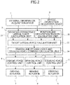
- FIG. 2 is a functional block diagram of control unit 3.
- Control unit 3 has a function as a controller that obtains the target lateral force for allowing vehicle 10 to follow the target travel path and outputs a control command for achieving the target lateral force to each of actuators 7 to 9.
- Control unit 3 includes a deviation corrective lateral force calculation unit 31, a position and orientation priority calculation unit 32, a target lateral force calculation unit 33, and a braking and driving forces and steering force command calculation unit 34.
- Deviation corrective lateral force calculation unit 31 acquires the target travel path on which vehicle 10 travels that is obtained on the basis of the external information acquired by external information acquisition device 1.
- Deviation corrective lateral force calculation unit 31 obtains a translation force for tracing the position of vehicle 10 on the target travel path on the basis of a lateral displacement amount which is the amount of displacement of vehicle 10 in the lateral direction with respect to a target movement point in the target travel path.
- Deviation corrective lateral force calculation unit 31 also obtains a rotational force for correcting the direction of vehicle 10 with respect to the target travel path on the basis of an orientation displacement amount which is the amount of displacement of vehicle 10 in a yaw direction with respect to the target movement point.
- Position and orientation priority calculation unit 32 calculates a priority as a weighting variable used for a process for weighting the translation force and the rotational force, on the basis of the external information acquired by external information acquisition device 1 and the information on vehicle 10 acquired by vehicle information acquisition device 2, that is, specifications relating to traveling of vehicle 10.
- the specifications relating to traveling of vehicle 10 in position and orientation priority calculation unit 32 include the understeer tendency and the oversteer tendency of vehicle 10, a rate of change in a curvature of the target travel path, a road width including the target travel path on which vehicle 10 travels, a deceleration of vehicle 10, and the like.
- Target lateral force calculation unit 33 inputs the translation force and the rotational force obtained by deviation corrective lateral force calculation unit 31, and the priority obtained by position and orientation priority calculation unit 32, obtains a weighted translation force and a weighted rotational force by weighting the translation force and the rotational force, and obtains the target lateral force by adding the weighted translation force and the weighted rotational force.
- Braking and driving forces and steering force command calculation unit 34 freely allocates the target lateral force obtained by target lateral force calculation unit 33 to the driving force, the braking force, and the steering force, obtains the target driving force, the target braking force, and the target steering force which are control commands for achieving the target lateral force, and outputs the control commands corresponding to respective targets to driving actuator 7, braking actuator 8, and steering actuator 9.
- FIG. 3 is a flowchart illustrating a main routine of a process for calculating the target lateral force by control unit 3.
- control unit 3 obtains the translation force for tracing the position of vehicle 10 on the target travel path on the basis of the lateral displacement amount of vehicle 10 with respect to the target movement point, and obtains the rotational force for correcting the orientation of vehicle 10 with respect to the target travel path on the basis of the orientation displacement amount of vehicle 10 in the yaw direction with respect to the target movement point.
- control unit 3 obtains the priority for weighting the translation force and the rotational force obtained in S100, on the basis of the specifications relating to traveling of vehicle 10, such as the tendency to understeer and oversteer of vehicle 10.
- control unit 3 obtains the weighted translation force and the weighted rotational force obtained by weighting the translation force and the rotational force, on the basis of the translation force and rotational force obtained in step S100 and the priority obtained in step S200, and obtains the target lateral force by adding the weighted translation force and the weighted rotational force.
- step S100 the process for calculating the translation force and the rotational force by deviation corrective lateral force calculation unit 31 in step S100 will now be described in detail with reference to the flowchart of FIG. 4 .
- control unit 3 calculates a lateral displacement amount ERTP, which is the amount of displacement of vehicle 10 in the lateral direction with respect to the target movement point, which is obtained from external information acquisition device 1, and calculates a position deviation corrective lateral force FY ERTP on the basis of lateral displacement amount ERTP, that is, the position deviation, in accordance with Equation 1.
- FY_ERTP m 2 TP 2 ⁇ ERTP
- Equation 1 m represents the weight of vehicle 10
- TP represents the time at which vehicle 10 wishes to reach the target movement point on the target travel path from the current position.
- lateral force FY ERTP corresponds to the lateral force for the translation motion, that is, the translation force.
- lateral force FY ERTP is calculated as the translation force that eliminates lateral displacement amount ERTP and causes the position of vehicle 10 to trace the target travel path.
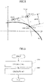
- FIG. 5 illustrates an aspect of a process for calculating lateral displacement amount ERTP. Note that FIG. 5 illustrates the current position, predicted movement point, and target movement point of vehicle 10 in a horizontal coordinate system.
- Control unit 3 obtains a straight line L2 that is orthogonal to a straight line L1 connecting the current position and the predicted movement point after a time period TP and passes through the predicted movement point, obtains the point where straight line L2 intersects the target travel path as the target movement point, and obtains the distance between the predicted movement point and the target movement point as lateral displacement amount ERTP.
- control unit 3 obtains coordinates (xtp, ytp) of the predicted movement point after time period TP on the basis of the coordinates (x0, y0) of the current position of vehicle 10 obtained from external information acquisition device 1 and an orientation ⁇ ap of current vehicle 10, in accordance with Equation 2.
- x tp x 0 + V ⁇ TP ⁇ cos ⁇ ap
- y tp y 0 + V ⁇ TP ⁇ sin ⁇ ap
- Equation 2 V represents the vehicle speed.
- control unit 3 obtains a function f(x) ort that is orthogonal to straight line L1 passing through the coordinates (x tp , y tp ) of the predicted movement point and connecting the coordinates (x0, y0) of the current position and the coordinates (xtp, ytp) of the predicted movement point, in accordance with Equation 3.
- f x ort ⁇ 1 tan ⁇ ap ⁇ x + y tp + 1 tan ⁇ ap ⁇ x tp
- control unit 3 calculates the coordinates (x tgt , y tgt ) of the target movement point from function f(x) ort passing through the coordinates (xtp, ytp) of the predicted movement point and a function f(x) representing the target travel path (target travel locus), in accordance with Equation 4.
- Control unit 3 then calculates lateral displacement amount ERTP, which is the distance between the predicted movement point and the target movement point, from the coordinates (x tp , y tp ) of the predicted movement point and the coordinates (x tgt , y tgt ) of the target movement point, in accordance with Equation 5.
- ERTP x tgt ⁇ x tp 2 + y tgt ⁇ y tp 2
- control unit 3 calculates an orientation deviation corrective lateral force FY ⁇ in accordance with Equation 6, on the basis of an orientation displacement amount ⁇ de, which is the amount of displacement of vehicle 10 in the yaw direction with respect to the target movement point.
- FY_ ⁇ m ⁇ de TP ⁇ V
- orientation displacement amount ⁇ de is a deviation between an orientation ⁇ tgt of vehicle 10 at the target movement point when vehicle 10 traces the target travel path and an orientation ⁇ ap of vehicle 10 at the present time, and is calculated according to Equation 7.
- ⁇ de ⁇ tgt ⁇ ⁇ ap
- an angle formed by a tangent line of the target travel path at the target movement point and the x-axis is the orientation ⁇ tgt
- an angle formed by straight line L1 and the x-axis is the orientation ⁇ ap.
- an inclination angle in the direction in which the value of the y-coordinate drops is indicated by a plus sign
- an inclination angle in the direction in which the value of the y-coordinate increases is indicated by a minus sign. Therefore, in the example in FIG. 5 , the orientation ⁇ tgt is represented by a positive angle, the orientation ⁇ ap is represented by a negative angle, and the orientation displacement amount ⁇ de is a sum of the absolute value of the orientation ⁇ tgt and the absolute value of the orientation ⁇ ap.
- lateral force FY ⁇ corresponds to the lateral force for the rotational motion, that is, the rotational force.
- lateral force FY ⁇ is calculated as the rotational force for correcting the orientation of vehicle 10 with respect to the target travel path.
- step S200 The process for calculating the priority by position and orientation priority calculation unit 32 in step S200 is described next in detail with reference to the flowchart of FIG. 6 .
- control unit 3 calculates a priority W1 (0 ⁇ W1 ⁇ 1) as a weighting variable for position deviation correction, on the basis of information relating to the specifications relating to traveling of vehicle 10, which is the information acquired by external information acquisition device 1 or vehicle information acquisition device 2.
- the specifications relating to traveling of vehicle 10 that are used by control unit 3 to calculate priority W1 are information on the tendency to understeer and oversteer of vehicle 10, the rate of change in the curvature of the target travel path, the road width on which vehicle 10 travels, and travel conditions relating to vehicle behavior stability such as deceleration of vehicle 10 and course traceability of vehicle 10.
- control unit 3 obtains a priority W2 (0 ⁇ W2 ⁇ 1) as a weighting variable for orientation deviation correction, on the basis of priority W1 for position deviation correction obtained in step S201.
- control unit 3 obtains priority W2 for the orientation deviation correction, in accordance with Equation 9.
- step S300 The process for calculating the target lateral force in step S300 performed by target lateral force calculation unit 33 will be described hereinafter in detail with reference to the flowchart of FIG. 7 .
- control unit 3 calculates a position deviation corrective lateral force FY1 corresponding to the weighted translation force in accordance with Equation 10, on the basis of position deviation corrective lateral force FY ERTP obtained in step S101 and priority W1 for position deviation correction that is obtained in step S201.
- FY 1 FY_ERTP ⁇ W1
- control unit 3 calculates orientation deviation corrective lateral force FY2 corresponding to the weighted rotational force in accordance with Equation 11, on the basis of orientation deviation corrective lateral force FY ⁇ obtained in step S102 and priority W2 for orientation deviation correction that is obtained in step S202.
- FY 2 FY _ ⁇ ⁇ W 2
- control unit 3 calculates a final target lateral force FY in accordance with Equation 12, on the basis of position deviation corrective lateral force FY1 obtained in step S301 and orientation deviation corrective lateral force FY2 obtained in step S302.
- FY FY1 + FY 2
- control unit 3 sets, as final target lateral force FY, a sum obtained by adding position deviation corrective lateral force FY1 (weighted translation force) obtained by multiplying position deviation corrective lateral force FY ERTP by priority W1 and orientation deviation corrective lateral force FY2 (weighted rotational force) obtained by multiplying orientation deviation corrective lateral force FY ⁇ by priority W2.
- position deviation corrective lateral force FY1 weighted translation force
- orientation deviation corrective lateral force FY2 weighted rotational force
- priority W1 is 0.5 and priority W2 is also 0.5
- position deviation corrective lateral force FY ERTP and orientation deviation corrective lateral force FY ⁇ are reflected in target lateral force FY at the same ratio, whereby orientation deviation correction and position deviation correction are executed at the same level.
- priority W1 becomes greater than 0.5
- the ratio of position deviation corrective lateral force FY ERTP to target lateral force FY increases, and the position deviation correction is executed in preference to the orientation deviation correction.
- priority W1 decreases to less than 0.5
- the ratio of the orientation deviation corrective lateral force FY ⁇ to target lateral force FY increases, and the orientation deviation correction is executed in preference to the position deviation correction.
- control unit 3 variably sets priorities W1 and W2 according to the specifications relating to traveling of vehicle 10, such as the tendency to understeer and oversteer of vehicle 10, the balance between course traceability and behavior stability can be optimized in accordance with the specifications relating to traveling of vehicle 10.
- control unit 3 sets priorities W1 and W2 on the basis of the understeer tendency and the oversteer tendency which are specifications relating to traveling of vehicle 10.
- FIG. 8 illustrates an aspect of a map (conversion table) that control unit 3 refers to in step S201 to obtain priority W1 of position deviation correction on the basis of the understeer tendency and the oversteer tendency.
- the degree of understeer and the degree of oversteer are set on the x-axis
- priority W1 for position deviation correction is set on the y-axis
- priority W1 for position deviation correction is obtained on the basis of the degree of understeer and the degree of oversteer.
- the origin of the x-axis corresponds to neutral steering
- the positive direction from the origin indicates the oversteer tendency
- the negative direction from the origin indicates the understeer tendency
- priority W1 is set at 0.5, which is a median value, and as the degree of oversteer increases, priority W1 gradually decreases from 0.5 to reach zero. As the degree of understeer increases, priority W1 gradually increases from 0.5 to reach 1.
- priority W1 and priority W2 are set at 0.5 which is the median value
- the position deviation correction and the orientation deviation correction have the same level of priority
- the sum of half of position deviation corrective lateral force FY ERTP and half of orientation deviation corrective lateral force FY ⁇ is set as final target lateral force FY.
- the correlation of the degree of understeer and the degree of oversteer with priority W1 is not limited to the characteristics illustrated in FIG. 8 ; the higher the degree of oversteer, the smaller priority W1 may be than priority W2, and the higher the degree of understeer, the higher priority W1 may tend to be than priority W2.
- priority W1 for position deviation correction when vehicle 10 tends to oversteer, the higher the degree of oversteer, the lower priority W1 for position deviation correction is maintained by control unit 3, and control unit 3 sets priority W2 for orientation deviation correction relatively high.
- control unit 3 prioritizes the orientation deviation correction over the position deviation correction and stabilizes the unstable behavior of vehicle 10, thereby ensuring the stability of the vehicle behavior.
- control unit 3 keeps priority W2 for orientation deviation correction relatively low.
- control unit 3 secures the course traceability by prioritizing the position deviation correction over the orientation deviation correction and moving the course of vehicle 10 with respect to the target travel path.
- control unit 3 sets priorities W1 and W2 in accordance with the tendency to understeer and oversteer, thereby adjusting the balance between the course traceability and the behavior stability to an appropriate balance according to the tendency to understeer and oversteer of vehicle 10.
- control unit 3 sets priorities W1 and W2 on the basis of the rate of change in the curvature of the target travel path which is one of the specifications relating to traveling of vehicle 10, that is, the change in a turning radius.
- FIG. 9 illustrates an aspect of a map (conversion table) that control unit 3 refers to in step S201 to obtain priority W1 for position deviation correction on the basis of the rate of change in the curvature of the target travel path.
- the rate of change in the curvature of the target travel path is set on the x-axis
- priority W1 for position deviation correction is set on the y-axis
- priority W1 for position deviation correction is obtained on the basis of the rate of change in the curvature of the target travel path.
- the rate of change in the curvature When the rate of change in the curvature is zero, it means that the curvature of the target travel path is constant, and when the rate of change in the curvature takes a positive value, it means that the curvature is increasing and that the curving is sharp. Conversely, when the rate of change in the curvature takes a negative value, it means that the curvature is decreasing and that the curving is mild.
- the state in which the curving is sharp is the state in which vehicle 10 is traveling near the entrance of the curve
- the state in which the curving is mild is the state in which vehicle 10 is traveling near the exit of the curve.
- priority W1 is set at approximately 0.5, which is the median value. Priority W1 gradually increases from 0.5 to reach 1 as the rate of change in the curvature increases in the positive direction, and priority W1 gradually decreases from 0.5 to reach zero as the rate of change in the curvature increases in the negative direction.
- priority W1 may become greater than priority W2 when the curvature is increasing, and priority W1 may tend to be less than priority W2 when the curvature is decreasing.
- control unit 3 makes priority W1 for position deviation correction higher than priority W2 for orientation deviation correction when vehicle 10 travels near the entrance of the curve, thereby increasing the course traceability to the target travel path that is set for the curve, and ensuring the travel stability of vehicle 10 traveling on the curve.
- control unit 3 increases the ratio of position deviation corrective lateral force FY1 (weighted translation force) to orientation deviation corrective lateral force FY2 (weighted rotational force), to improve the course traceability to the target travel path that is a curve.
- control unit 3 makes priority W2 for orientation deviation correction higher than priority W1 for position deviation correction, thereby ensuring the stability of the vehicle behavior in a straight section after the curve.
- control unit 3 increases the ratio of orientation deviation corrective lateral force FY2 (weighted rotational force) to position deviation corrective lateral force FY1 (weighted translation force), to ensure the stability of the vehicle behavior after the curve.
- control unit 3 sets priorities W1 and W2 in accordance with the rate of change in the curvature of the target travel path, thereby adjusting the balance between the course traceability and the behavior stability to an appropriate balance according to the changes in the curvature of the target travel path.
- control unit 3 sets priorities W1 and W2 on the basis of the road width which is one of the specifications relating to travel of vehicle 10, that is, more specifically, the road width including the target travel path in which vehicle 10 travels.
- FIG. 10 illustrates an aspect of a map (conversion table) that control unit 3 refers to in step S201 to obtain priority W1 for position deviation correction on the basis of the road width.
- the value obtained by dividing the vehicle width by the lane width is taken as a road width index value RWI (index value RWI > 0), the index value RWI being taken as the x-axis, and priority W1 for position deviation correction is taken as the y-axis and obtained from index value RWI related to the road width.
- index value RWI (0 ⁇ RWI ⁇ 1) becomes smaller as the lane width becomes wider than the vehicle width.
- the index value RWI indicates a margin ratio of the lane width to the vehicle width.
- the smaller index value RWI is, the wider the lane width and the higher the margin ratio of the lane width with respect to the vehicle width, and conversely, the larger the index value RWI is, the narrower the lane width and the lower the margin ratio of the lane width with respect to the vehicle width.
- a state in which index value RWI is small that is, a state in which the margin ratio is high, is a state in which traveling within the lane width is easy and the risk of collision with the surrounding environment is small.
- a state in which index value RWI is large that is, a state in which the margin ratio is low, is a state in which the risk of going off course or collision increases.
- priority W1 (W1 > 0) for position deviation correction is set at 1, and as index value RWI becomes smaller than 1, that is, as the lane width increases, priority W1 is gradually reduced.
- index value RWI and priority W1 are not limited to the characteristics illustrated in FIG. 10 , but the characteristic may be such that priority W1 is changed to a higher value as the lane width becomes narrower than the vehicle width.
- the map for obtaining priority W1 is set as the map for obtaining priority W1 from the road width or the lane width, and the characteristics of the relevant map can be changed in accordance with the vehicle width of vehicle 10.
- control unit 3 sets priority W1 for position deviation correction higher as the road width becomes narrower and index value RWI becomes closer to 1, and keeps priority W2 for orientation correction relatively low.
- control unit 3 sets priority W1 for position deviation correction high, thereby improving course traceability and ensuring travel stability.
- control unit 3 increases the ratio of position deviation corrective lateral force FY1 (weighted translation force) to the orientation deviation corrective lateral force FY2 (weighted rotational force), to improve the course traceability.
- control unit 3 can adjust the balance between the course traceability and the behavior stability to an appropriate balance according to the road width by setting priorities W1 and W2 according to the road width.
- control unit 3 sets priorities W1 and W2 on the basis of deceleration DE which is one of the specifications relating to traveling of vehicle 10.
- FIG. 11 illustrates an aspect of a map (conversion table) that control unit 3 refers to in step S201 to obtain priority W1 for position deviation correction on the basis of deceleration DE of vehicle 10.
- deceleration DE is set on the x-axis
- priority W1 for position deviation correction is set on the y-axis
- priority W1 (W1 > 0) for position deviation correction is obtained from deceleration DE.
- deceleration DE of vehicle 10 is a negative acceleration, which is the amount of decrease in the vehicle speed per unit time.
- the positive direction from the origin means a deceleration operation state of vehicle 10, wherein deceleration DE (decrease in vehicle speed per unit time) increases as the distance from the origin increases in the positive direction.
- priority W1 (0 ⁇ W1 ⁇ 1) when deceleration DE is zero, priority W1 gradually increases to reach 1 as deceleration DE increases.
- deceleration DE deceleration DE
- priority W1 is changed to a higher value as deceleration DE increases, that is, at the time of sudden deceleration.
- control unit 3 enhances the course traceability by setting priority W1 for the position deviation correction high when the urgency is high, such as when, for example, sudden braking is implemented to avoid danger, and thereby improves the safety of vehicle 10.
- control unit 3 can adjust the balance between the course traceability and the behavior stability to an appropriate balance according to deceleration DE by setting priorities W1 and W2 in accordance with deceleration DE.
- control unit 3 can obtain the lateral displacement amount and the orientation displacement amount in consideration of the lateral displacement amount and the orientation displacement amount caused by the centripetal force according to the curvature of the target travel path at the target movement point.
- An embodiment having such a configuration will be described hereinafter.
- FIG. 12 is a diagram illustrating the lateral displacement amount and the orientation displacement amount caused by the centripetal force according to the curvature of the target travel path at the target movement point in the horizontal coordinate system.
- FIG. 13 is a functional block diagram of control unit 3 that obtains the lateral displacement amount and the orientation displacement amount in consideration of the centripetal force according to the curvature of the target travel path at the target movement point.
- control unit 3 functioning as a controller includes position and orientation priority calculation unit 32, target lateral force calculation unit 33, braking and driving forces and steering force command calculation unit 34, a centripetal force-based deviation calculation unit 35, a position and orientation deviation calculation unit 36, and a deviation corrective lateral force calculation unit 37.
- position and orientation priority calculation unit 32, target lateral force calculation unit 33, and braking and driving force and steering force command calculation unit 34 that are illustrated in FIG. 13 have the same functions as those illustrated in the functional block diagram of FIG. 2 , detailed descriptions thereof are omitted accordingly.
- Centripetal force-based deviation calculation unit 35 calculates a centripetal force FY ⁇ according to a curvature ⁇ of the target travel path at the target movement point (xtgt, ytgt).
- Centripetal force-based deviation calculation unit 35 also calculates a lateral displacement amount ERTP ⁇ , which is a lateral movement component of vehicle 10 with respect to the predicted movement point generated based on the centripetal force FY ⁇ , and an orientation displacement amount ⁇ ⁇ , which is a displacement amount of vehicle 10 in the yaw direction with respect to the predicted movement point generated based on the centripetal force FY ⁇ .
- Position and orientation deviation calculation unit 36 obtains lateral deviation amount ER at the target movement point in consideration of lateral displacement amount ERTP ⁇ based on centripetal force FY ⁇ , and obtains orientation displacement amount ⁇ mp at the target movement point in consideration of the orientation displacement amount ⁇ _ ⁇ based on centripetal force FY ⁇ .
- Deviation corrective lateral force calculation unit 37 obtains position deviation corrective lateral force FY_ER on the basis of lateral displacement amount ER, and obtains orientation deviation corrective lateral force FY_ ⁇ mp on the basis of orientation displacement amount ⁇ mp.
- position and orientation priority calculation unit 32 calculates priorities W1 and W2 on the basis of the specifications relating to traveling of vehicle 10, such as the tendency to understeer and oversteer.
- Target lateral force calculation unit 33 weights position deviation corrective lateral force FY ER and orientation deviation corrective lateral force FY_ ⁇ mp according to priorities W1 and W2, respectively, and calculates position deviation corrective lateral force FY1 (weighted translation force) and orientation deviation corrective lateral force FY2 (weighted rotational force).
- target lateral force calculation unit 33 adds up position deviation corrective lateral force FY1, orientation deviation corrective lateral force FY2, and centripetal force FY ⁇ corresponding to curvature ⁇ at the target movement point, to obtain final target lateral force FY
- Braking and driving force and steering force command calculation unit 34 inputs target lateral force FY obtained by target lateral force calculation unit 33, freely distributes the input target lateral force FY to the driving force, braking force, and steering force, obtains a target driving force, a target braking force, and a target steering force, which are control commands for achieving target lateral force FY, and outputs control commands corresponding to respective targets to driving actuator 7, braking actuator 8, and steering actuator 9.
- FIG. 14 is a flowchart illustrating a main routine for the process for calculating target lateral force FY by control unit 3.
- control unit 3 calculates lateral displacement amount ERTP ⁇ and orientation displacement amount ⁇ _ ⁇ caused by centripetal force FY_ ⁇ .
- control unit 3 obtains lateral displacement amount ER and orientation displacement amount ⁇ mp in consideration of lateral displacement amount ERTP ⁇ and orientation displacement amount ⁇ _ ⁇ .
- control unit 3 obtains position deviation corrective lateral force FY ER, which is a translation force for causing the position of vehicle 10 to trace the target travel path, on the basis of lateral displacement amount ER, and obtains orientation deviation corrective lateral force FY_ ⁇ mp, which is a rotational force for correcting the orientation of vehicle 10 with respect to the target travel path, on the basis of orientation displacement amount ⁇ mp.
- control unit 3 sets priority W1 of position deviation corrective lateral force FY_ER and priority W2 of orientation deviation corrective the lateral force FY ⁇ mp, on the basis of the specifications relating to traveling of vehicle 10, such as the tendency to understeer and oversteer of vehicle 10.
- control unit 3 obtains target lateral force FY by adding up position deviation corrective lateral force FY1, which is the result of weighting position deviation corrective lateral force FY_ER with priority W1, orientation deviation corrective lateral force FY2, which is the result of weighting orientation deviation corrective lateral force FY_ ⁇ mp with priority W2, and centripetal force FY_ ⁇ corresponding to curvature ⁇ at the target movement point.
- step S500 performed by control unit 3
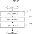
- control unit 3 the details of the process in step S500 performed by control unit 3 will be described in detail with reference to the flowchart of FIG. 15 .
- control unit 3 calculates centripetal force FY_ ⁇ according to Equation 13, on the basis of curvature ⁇ of the target travel path at the target movement point.
- FY ⁇ ⁇ m ⁇ ⁇ ⁇ V 2
- control unit 3 obtains centripetal force FY_ ⁇ on the basis of a physical quantity related to curvature ⁇ at the target movement point and a physical quantity related to velocity V of vehicle 10.
- control unit 3 calculates lateral displacement amount ERTP ⁇ , which is a lateral movement component of vehicle 10 with respect to the predicted movement point generated by centripetal force FY ⁇ , in accordance with Equation 14.
- ERTP _ ⁇ 1 2 ⁇ ⁇ ⁇ V 2 ⁇ TP 2
- control unit 3 calculates orientation deviation amount ⁇ ⁇ , which is a change component of vehicle 10 in the yaw direction with respect to the predicted movement point generated based on centripetal force FY ⁇ , in accordance with Equation 15.
- ⁇ _ ⁇ ⁇ ⁇ V ⁇ TP
- step S600 performed by control unit 3
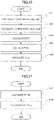
- control unit 3 the details of the process in step S600 performed by control unit 3 will be described in detail with reference to the flowchart of FIG. 16 .
- control unit 3 calculates the coordinates (x tp , y tp ) of the predicted movement point after time period TP on the basis of the coordinates (x0, y0) of the current position of vehicle 10 and the current orientation ⁇ ap of vehicle 10.
- control unit 3 obtains a function f(x) ort that passes through the coordinates (xtp, ytp) of the predicted movement point and is orthogonal to the line connecting the coordinates (x0, y0) of the current position and the coordinates (xtp, ytp) of the predicted movement point, in accordance with Equation 3 described above.
- control unit 3 also calculates the coordinates (x tgt , y tgt ) of the target movement point from the function f(x) ort passing through the coordinates (xtp, ytp) of the predicted movement point and the function f(x) representing the target travel path (target travel track), in accordance with Equation 4 described above.
- control unit 3 calculates lateral displacement amount ERTP, which is the amount of lateral displacement of vehicle 10 with respect to the target movement point, from the coordinates (x tp , y tp ) of the predicted movement point and the coordinates (x tgt , y tgt ) of the target movement point, in accordance with Equation 5 described above.
- control unit 3 calculates final lateral displacement amount ER in accordance with Equation 16, on the basis of lateral displacement amount ERTP k which is a first lateral displacement amount obtained in step S502, and lateral displacement amount ERTP which is a second lateral displacement amount obtained in step S603 (see FIG. 12 ).
- ER ERTP ⁇ ERTP_ ⁇
- control unit 3 calculates final orientation displacement amount ⁇ mp in accordance with Equation 17, on the basis of orientation ⁇ ap of vehicle 10 at the current point, orientation ⁇ tgt of vehicle 10 at the target movement point, and orientation displacement amount ⁇ k obtained in step S503 (see FIG. 12 ).
- ⁇ mp ⁇ tgt ⁇ ⁇ ap ⁇ ⁇ _ ⁇
- step S700 performed by control unit 3
- control unit 3 the details of the process in step S700 performed by control unit 3 will be described in detail with reference to the flowchart of FIG. 17 .
- control unit 3 calculates position deviation corrective lateral force FY_ER in accordance with Equation 18, on the basis of lateral displacement amount ER obtained in step S604.
- FY _ ER m ⁇ 2 TP 2 ⁇ ER
- control unit 3 calculates orientation deviation corrective lateral force FY_ ⁇ mp in accordance with Equation 19, on the basis of orientation displacement amount ⁇ mp obtained in step S605.
- FY _ ⁇ mp m ⁇ ⁇ mp TP ⁇ V
- step S800 the process for setting priorities W1 and W2 in step S800 performed by control unit 3 will be described with reference to the flowchart of FIG. 18 .
- control unit 3 obtains priority W1 for position deviation correction (weighting variable for position deviation correction) on the basis of the specifications relating to traveling of vehicle 10, such as the tendency to understeer and oversteer, the rate of change in the curvature of the target travel path, the road width, and the deceleration of vehicle 10.
- control unit 3 calculates priority W1 on the basis of the specifications relating to traveling of vehicle 10, as with step S201 described above.
- the characteristics of priority W1 with respect to the tendency to understeer and oversteer, the rate of change in the curvature of the target travel path, the road width, and the deceleration of vehicle 10 are as illustrated in FIGS. 8 to 11 .
- control unit 3 obtains priority W2 for orientation deviation correction (weighting variable for orientation deviation correction) on the basis of priority W1 for position deviation correction obtained in step S801.
- control unit 3 obtains priority W2 for orientation deviation correction in accordance with Equation 9, as with step S202 described above.
- step S900 performed by control unit 3
- control unit 3 the details of the process in step S900 performed by control unit 3 will be described in detail with reference to the flowchart of FIG. 19 .
- control unit 3 calculates position deviation corrective lateral force FY1 in accordance with Equation 20, on the basis of priority W1 for position deviation correction obtained in step S801 and position deviation corrective lateral force FY_ER obtained in step S701.
- control unit 3 weights position deviation corrective lateral force FY_ER based on priority W1, to obtain position deviation corrective lateral force FY1 corresponding to the weighted translation force.
- FY 1 FY _ ER ⁇ W 1
- control unit 3 calculates orientation deviation corrective lateral force FY2 in accordance with Equation 21, on the basis of priority W2 orientation deviation correction obtained in step S802 and orientation deviation corrective lateral force FY_ ⁇ mp obtained in step S702.
- control unit 3 weights orientation deviation corrective lateral force FY_ ⁇ mp based on priority W2, to obtain orientation deviation corrective lateral force FY2 corresponding to the weighted rotational force.
- FY 2 FY _ ⁇ mp ⁇ W 2
- control unit 3 calculates final target lateral force FY in accordance with Equation 22, on the basis of position deviation corrective lateral force FY1 obtained in step S901, orientation deviation corrective lateral force FY2 obtained in step S902, and centripetal force FY_ ⁇ corresponding to the curvature ⁇ at the target movement point that is obtained in step S501.
- FY FY1 + FY 2 + FY _ ⁇
- control unit 3 since control unit 3 obtains the position deviation corrective lateral force and the orientation deviation corrective lateral force in consideration of the lateral displacement amount and the orientation displacement amount caused by centripetal force FY ⁇ , control unit 3 can accurately obtain the lateral force (translation force) for causing vehicle 10 to trace the target travel path and the lateral force (rotational force) for correcting the orientation of vehicle 10 with respect to the target travel path.
- control unit 3 sets priorities W1 and W2 on the basis of the tendency to understeer and oversteer, the rate of change in the curvature of the target travel path, the road width, and the deceleration, thereby adjusting the balance between the course traceability (position deviation correction) and the behavior stability (orientation deviation correction) to an appropriate balance according to the specifications (travel conditions) relating to traveling of vehicle 10.
- the specifications relating to traveling of vehicle 10 that are used to set priorities W1 and W2 are the understeer tendency, and the oversteer tendency, the rate of change in the curvature of the target travel path, the road width, and the deceleration, but are not limited thereto.
- control unit 3 can set priorities W1 and W2 on the basis of specifications relating to traveling of vehicle 10 that affect the course traceability and behavior stability of vehicle 10, the specifications including a friction coefficient of a road surface, the strength of the crosswind, a movable load, a degree of tire wear, a tire pressure, a road surface gradient, and a lateral inclination angle of the road surface (i.e., turning inclination angle).
- Control unit 3 can also set priorities W1 and W2 by combining a plurality of these specifications relating to traveling of vehicle 10 that are described above.
- control unit 3 can obtain final priorities W1 and W2 by weighting priorities W1 and W2 obtained for each element.
- control unit 3 can change priorities W1 and W2 when vehicle 10 tends to either understeer or oversteer, such as when, for example, vehicle 10 tends to oversteer.
- control unit 3 can calculate priority W2 for orientation deviation correction according to the specifications relating to traveling of vehicle 10, and can obtain priority W1 for position deviation correction from the calculated priority W2 for orientation deviation correction. Control unit 3 can also use the map in which priority W1 and priority W2 can be obtained together according to the specifications relating to traveling of vehicle 10.
- the sum of priority W1 for position deviation correction and priority W2 for orientation deviation correction is 1, but the sum is not limited to 1 and can be any value.
- control unit 3 can change the sum in accordance with the level of automatic driving, such as by setting the sum lower when a driving support control is executed, compared to when vehicle 10 runs automatically.
Landscapes
- Engineering & Computer Science (AREA)
- Transportation (AREA)
- Mechanical Engineering (AREA)
- Chemical & Material Sciences (AREA)
- Combustion & Propulsion (AREA)
- Automation & Control Theory (AREA)
- Human Computer Interaction (AREA)
- Physics & Mathematics (AREA)
- Mathematical Physics (AREA)
- Theoretical Computer Science (AREA)
- Steering Control In Accordance With Driving Conditions (AREA)
- Control Of Driving Devices And Active Controlling Of Vehicle (AREA)
Applications Claiming Priority (2)
| Application Number | Priority Date | Filing Date | Title |
|---|---|---|---|
| JP2019136815 | 2019-07-25 | ||
| PCT/JP2020/020455 WO2021014741A1 (ja) | 2019-07-25 | 2020-05-25 | 車両運動制御装置、車両運動制御方法、及び車両運動制御システム |
Publications (3)
| Publication Number | Publication Date |
|---|---|
| EP4005882A1 true EP4005882A1 (de) | 2022-06-01 |
| EP4005882A4 EP4005882A4 (de) | 2023-08-30 |
| EP4005882B1 EP4005882B1 (de) | 2024-04-10 |
Family
ID=74192883
Family Applications (1)
| Application Number | Title | Priority Date | Filing Date |
|---|---|---|---|
| EP20844894.4A Active EP4005882B1 (de) | 2019-07-25 | 2020-05-25 | Fahrzeugbewegungssteuerungsvorrichtung, fahrzeugbewegungssteuerungsverfahren und fahrzeugbewegungssteuerungssystem |
Country Status (4)
| Country | Link |
|---|---|
| US (1) | US12077154B2 (de) |
| EP (1) | EP4005882B1 (de) |
| JP (1) | JP7249416B2 (de) |
| WO (1) | WO2021014741A1 (de) |
Cited By (1)
| Publication number | Priority date | Publication date | Assignee | Title |
|---|---|---|---|---|
| EP4617127A1 (de) * | 2024-03-11 | 2025-09-17 | thyssenkrupp Presta Aktiengesellschaft | Kraftfahrzeug und verfahren zum abbremsen eines kraftfahrzeugs mit einem vehicle-motion-control-system |
Families Citing this family (5)
| Publication number | Priority date | Publication date | Assignee | Title |
|---|---|---|---|---|
| WO2021174445A1 (zh) * | 2020-03-04 | 2021-09-10 | 华为技术有限公司 | 预测车辆驶出口的方法和装置 |
| JP7123994B2 (ja) * | 2020-03-27 | 2022-08-23 | 本田技研工業株式会社 | 車両制御システム |
| JP7505443B2 (ja) * | 2021-05-07 | 2024-06-25 | トヨタ自動車株式会社 | 遠隔監視装置、遠隔監視システム、遠隔監視方法、及び遠隔監視プログラム |
| JP7756523B2 (ja) * | 2021-09-13 | 2025-10-20 | Astemo株式会社 | 車両制御装置 |
| US12252127B2 (en) * | 2022-04-19 | 2025-03-18 | Aptiv Technologies AG | Dynamically calculating lane change trajectories |
Family Cites Families (5)
| Publication number | Priority date | Publication date | Assignee | Title |
|---|---|---|---|---|
| JP5359085B2 (ja) * | 2008-03-04 | 2013-12-04 | 日産自動車株式会社 | 車線維持支援装置及び車線維持支援方法 |
| US9296418B2 (en) * | 2013-01-23 | 2016-03-29 | Toyota Jidosha Kabushiki Kaisha | Vehicle control device |
| JP6138655B2 (ja) * | 2013-10-10 | 2017-05-31 | 日立オートモティブシステムズ株式会社 | 車両の運動制御装置 |
| JP6706166B2 (ja) | 2016-07-07 | 2020-06-03 | 株式会社Subaru | 車両の走行制御装置 |
| JP6911693B2 (ja) | 2017-10-11 | 2021-07-28 | トヨタ自動車株式会社 | 運転支援制御システム |
-
2020
- 2020-05-25 WO PCT/JP2020/020455 patent/WO2021014741A1/ja not_active Ceased
- 2020-05-25 JP JP2021534563A patent/JP7249416B2/ja active Active
- 2020-05-25 US US17/627,032 patent/US12077154B2/en active Active
- 2020-05-25 EP EP20844894.4A patent/EP4005882B1/de active Active
Cited By (2)
| Publication number | Priority date | Publication date | Assignee | Title |
|---|---|---|---|---|
| EP4617127A1 (de) * | 2024-03-11 | 2025-09-17 | thyssenkrupp Presta Aktiengesellschaft | Kraftfahrzeug und verfahren zum abbremsen eines kraftfahrzeugs mit einem vehicle-motion-control-system |
| BE1032462B1 (de) * | 2024-03-11 | 2025-10-06 | Thyssenkrupp Presta Ag | Kraftfahrzeug und Verfahren zum Abbremsen eines Kraftfahrzeugs mit einem Vehicle-Motion-Control-System |
Also Published As
| Publication number | Publication date |
|---|---|
| US20220266823A1 (en) | 2022-08-25 |
| EP4005882A4 (de) | 2023-08-30 |
| JP7249416B2 (ja) | 2023-03-30 |
| WO2021014741A1 (ja) | 2021-01-28 |
| JPWO2021014741A1 (de) | 2021-01-28 |
| EP4005882B1 (de) | 2024-04-10 |
| US12077154B2 (en) | 2024-09-03 |
Similar Documents
| Publication | Publication Date | Title |
|---|---|---|
| EP4005882B1 (de) | Fahrzeugbewegungssteuerungsvorrichtung, fahrzeugbewegungssteuerungsverfahren und fahrzeugbewegungssteuerungssystem | |
| US9669813B2 (en) | Vehicle driving support control device | |
| US8355842B2 (en) | Method and device for steering a motor vehicle | |
| JP7000765B2 (ja) | 車両の走行制御装置 | |
| US11708069B2 (en) | Obstacle avoidance apparatus and obstacle avoidance route generating apparatus | |
| EP3708464B1 (de) | Vorrichtung, verfahren, programm und system zur fahrzeugbewegungssteuerung sowie vorrichtung, verfahren, programm und system zur erstellung einer zielbahn | |
| EP2712780B1 (de) | Verfahren und Vorrichtung zur Fahrunterstützung | |
| EP3650257B1 (de) | Verfahren zur erzeugung der zielgeschwindigkeit eines fahrzeugs und vorrichtung zur erzeugung der zielgeschwindigkeit eines fahrzeugs für ein fahrhilfefahrzeug | |
| WO2019240002A1 (ja) | 車両制御装置、車両制御方法、及び車両制御システム | |
| WO2011080830A1 (ja) | 運転支援装置 | |
| JP7430214B2 (ja) | 制御演算装置 | |
| KR101846577B1 (ko) | 차선유지보조시스템 및 그 제어방법 | |
| JP6477253B2 (ja) | 車両走行制御装置 | |
| JP5239947B2 (ja) | 運転操作支援装置及び運転操作支援方法 | |
| KR20200017571A (ko) | 자율주행 차량을 위한 횡방향 제어 파라미터 보정 장치 및 방법 | |
| JP4024574B2 (ja) | 車両制御装置 | |
| EP4696577A1 (de) | Verfahren, vorrichtung, elektronische vorrichtung und medium zur fahrzeugseitensteuerung | |
| EP4353556B1 (de) | Fahrzeugsteuerungsverfahren und fahrzeugsteuerungsvorrichtung | |
| JP2018058494A (ja) | 車両制御装置、車両制御方法、および車両制御プログラム | |
| KR20190043270A (ko) | 차량 곡률 반경 추정 장치 및 방법 | |
| US20230030368A1 (en) | Vehicle control device | |
| JP7542475B2 (ja) | 走行制御方法及び走行制御装置 | |
| CN116940492A (zh) | 车辆控制装置、车辆控制方法以及车辆控制系统 | |
| Balachandran et al. | Creating predictive haptic feedback for obstacle avoidance using a model predictive control (MPC) framework | |
| EP4159566B1 (de) | Fahrzeuglenksystem |
Legal Events
| Date | Code | Title | Description |
|---|---|---|---|
| STAA | Information on the status of an ep patent application or granted ep patent |
Free format text: STATUS: THE INTERNATIONAL PUBLICATION HAS BEEN MADE |
|
| PUAI | Public reference made under article 153(3) epc to a published international application that has entered the european phase |
Free format text: ORIGINAL CODE: 0009012 |
|
| STAA | Information on the status of an ep patent application or granted ep patent |
Free format text: STATUS: REQUEST FOR EXAMINATION WAS MADE |
|
| 17P | Request for examination filed |
Effective date: 20211229 |
|
| AK | Designated contracting states |
Kind code of ref document: A1 Designated state(s): AL AT BE BG CH CY CZ DE DK EE ES FI FR GB GR HR HU IE IS IT LI LT LU LV MC MK MT NL NO PL PT RO RS SE SI SK SM TR |
|
| DAV | Request for validation of the european patent (deleted) | ||
| DAX | Request for extension of the european patent (deleted) | ||
| A4 | Supplementary search report drawn up and despatched |
Effective date: 20230731 |
|
| RIC1 | Information provided on ipc code assigned before grant |
Ipc: B62D 7/15 20060101ALN20230725BHEP Ipc: B62D 6/04 20060101ALN20230725BHEP Ipc: B60W 30/045 20120101ALN20230725BHEP Ipc: B60T 8/1755 20060101ALN20230725BHEP Ipc: B60T 7/22 20060101ALN20230725BHEP Ipc: B60W 50/00 20060101ALI20230725BHEP Ipc: B60W 10/20 20060101ALI20230725BHEP Ipc: B60W 10/18 20120101ALI20230725BHEP Ipc: B60W 10/04 20060101ALI20230725BHEP Ipc: B60W 30/10 20060101ALI20230725BHEP Ipc: B60W 30/02 20120101ALI20230725BHEP Ipc: B60T 8/17 20060101ALI20230725BHEP Ipc: B62D 6/00 20060101ALI20230725BHEP Ipc: B60T 7/12 20060101AFI20230725BHEP |
|
| RIC1 | Information provided on ipc code assigned before grant |
Ipc: B62D 7/15 20060101ALN20231127BHEP Ipc: B62D 6/04 20060101ALN20231127BHEP Ipc: B60W 30/045 20120101ALN20231127BHEP Ipc: B60T 8/1755 20060101ALN20231127BHEP Ipc: B60T 7/22 20060101ALN20231127BHEP Ipc: B60W 50/00 20060101ALI20231127BHEP Ipc: B60W 10/20 20060101ALI20231127BHEP Ipc: B60W 10/18 20120101ALI20231127BHEP Ipc: B60W 10/04 20060101ALI20231127BHEP Ipc: B60W 30/10 20060101ALI20231127BHEP Ipc: B60W 30/02 20120101ALI20231127BHEP Ipc: B60T 8/17 20060101ALI20231127BHEP Ipc: B62D 6/00 20060101ALI20231127BHEP Ipc: B60T 7/12 20060101AFI20231127BHEP |
|
| GRAP | Despatch of communication of intention to grant a patent |
Free format text: ORIGINAL CODE: EPIDOSNIGR1 |
|
| STAA | Information on the status of an ep patent application or granted ep patent |
Free format text: STATUS: GRANT OF PATENT IS INTENDED |
|
| RIC1 | Information provided on ipc code assigned before grant |
Ipc: B62D 7/15 20060101ALN20231215BHEP Ipc: B62D 6/04 20060101ALN20231215BHEP Ipc: B60W 30/045 20120101ALN20231215BHEP Ipc: B60T 8/1755 20060101ALN20231215BHEP Ipc: B60T 7/22 20060101ALN20231215BHEP Ipc: B60W 50/00 20060101ALI20231215BHEP Ipc: B60W 10/20 20060101ALI20231215BHEP Ipc: B60W 10/18 20120101ALI20231215BHEP Ipc: B60W 10/04 20060101ALI20231215BHEP Ipc: B60W 30/10 20060101ALI20231215BHEP Ipc: B60W 30/02 20120101ALI20231215BHEP Ipc: B60T 8/17 20060101ALI20231215BHEP Ipc: B62D 6/00 20060101ALI20231215BHEP Ipc: B60T 7/12 20060101AFI20231215BHEP |
|
| INTG | Intention to grant announced |
Effective date: 20240115 |
|
| GRAS | Grant fee paid |
Free format text: ORIGINAL CODE: EPIDOSNIGR3 |
|
| GRAA | (expected) grant |
Free format text: ORIGINAL CODE: 0009210 |
|
| STAA | Information on the status of an ep patent application or granted ep patent |
Free format text: STATUS: THE PATENT HAS BEEN GRANTED |
|
| AK | Designated contracting states |
Kind code of ref document: B1 Designated state(s): AL AT BE BG CH CY CZ DE DK EE ES FI FR GB GR HR HU IE IS IT LI LT LU LV MC MK MT NL NO PL PT RO RS SE SI SK SM TR |
|
| REG | Reference to a national code |
Ref country code: GB Ref legal event code: FG4D |
|
| REG | Reference to a national code |
Ref country code: CH Ref legal event code: EP |
|
| REG | Reference to a national code |
Ref country code: DE Ref legal event code: R096 Ref document number: 602020028910 Country of ref document: DE |
|
| REG | Reference to a national code |
Ref country code: IE Ref legal event code: FG4D |
|
| REG | Reference to a national code |
Ref country code: LT Ref legal event code: MG9D |
|
| REG | Reference to a national code |
Ref country code: NL Ref legal event code: MP Effective date: 20240410 |
|
| REG | Reference to a national code |
Ref country code: AT Ref legal event code: MK05 Ref document number: 1674627 Country of ref document: AT Kind code of ref document: T Effective date: 20240410 |
|
| PG25 | Lapsed in a contracting state [announced via postgrant information from national office to epo] |
Ref country code: NL Free format text: LAPSE BECAUSE OF FAILURE TO SUBMIT A TRANSLATION OF THE DESCRIPTION OR TO PAY THE FEE WITHIN THE PRESCRIBED TIME-LIMIT Effective date: 20240410 |
|
| PG25 | Lapsed in a contracting state [announced via postgrant information from national office to epo] |
Ref country code: NL Free format text: LAPSE BECAUSE OF FAILURE TO SUBMIT A TRANSLATION OF THE DESCRIPTION OR TO PAY THE FEE WITHIN THE PRESCRIBED TIME-LIMIT Effective date: 20240410 |
|
| PG25 | Lapsed in a contracting state [announced via postgrant information from national office to epo] |
Ref country code: IS Free format text: LAPSE BECAUSE OF FAILURE TO SUBMIT A TRANSLATION OF THE DESCRIPTION OR TO PAY THE FEE WITHIN THE PRESCRIBED TIME-LIMIT Effective date: 20240810 |
|
| PG25 | Lapsed in a contracting state [announced via postgrant information from national office to epo] |
Ref country code: BG Free format text: LAPSE BECAUSE OF FAILURE TO SUBMIT A TRANSLATION OF THE DESCRIPTION OR TO PAY THE FEE WITHIN THE PRESCRIBED TIME-LIMIT Effective date: 20240410 |
|
| PG25 | Lapsed in a contracting state [announced via postgrant information from national office to epo] |
Ref country code: HR Free format text: LAPSE BECAUSE OF FAILURE TO SUBMIT A TRANSLATION OF THE DESCRIPTION OR TO PAY THE FEE WITHIN THE PRESCRIBED TIME-LIMIT Effective date: 20240410 Ref country code: FI Free format text: LAPSE BECAUSE OF FAILURE TO SUBMIT A TRANSLATION OF THE DESCRIPTION OR TO PAY THE FEE WITHIN THE PRESCRIBED TIME-LIMIT Effective date: 20240410 |
|
| PG25 | Lapsed in a contracting state [announced via postgrant information from national office to epo] |
Ref country code: GR Free format text: LAPSE BECAUSE OF FAILURE TO SUBMIT A TRANSLATION OF THE DESCRIPTION OR TO PAY THE FEE WITHIN THE PRESCRIBED TIME-LIMIT Effective date: 20240711 |
|
| PG25 | Lapsed in a contracting state [announced via postgrant information from national office to epo] |
Ref country code: PT Free format text: LAPSE BECAUSE OF FAILURE TO SUBMIT A TRANSLATION OF THE DESCRIPTION OR TO PAY THE FEE WITHIN THE PRESCRIBED TIME-LIMIT Effective date: 20240812 |
|
| PG25 | Lapsed in a contracting state [announced via postgrant information from national office to epo] |
Ref country code: ES Free format text: LAPSE BECAUSE OF FAILURE TO SUBMIT A TRANSLATION OF THE DESCRIPTION OR TO PAY THE FEE WITHIN THE PRESCRIBED TIME-LIMIT Effective date: 20240410 |
|
| PG25 | Lapsed in a contracting state [announced via postgrant information from national office to epo] |
Ref country code: AT Free format text: LAPSE BECAUSE OF FAILURE TO SUBMIT A TRANSLATION OF THE DESCRIPTION OR TO PAY THE FEE WITHIN THE PRESCRIBED TIME-LIMIT Effective date: 20240410 |
|
| PG25 | Lapsed in a contracting state [announced via postgrant information from national office to epo] |
Ref country code: PL Free format text: LAPSE BECAUSE OF FAILURE TO SUBMIT A TRANSLATION OF THE DESCRIPTION OR TO PAY THE FEE WITHIN THE PRESCRIBED TIME-LIMIT Effective date: 20240410 |
|
| PG25 | Lapsed in a contracting state [announced via postgrant information from national office to epo] |
Ref country code: LV Free format text: LAPSE BECAUSE OF FAILURE TO SUBMIT A TRANSLATION OF THE DESCRIPTION OR TO PAY THE FEE WITHIN THE PRESCRIBED TIME-LIMIT Effective date: 20240410 |
|
| PG25 | Lapsed in a contracting state [announced via postgrant information from national office to epo] |
Ref country code: PT Free format text: LAPSE BECAUSE OF FAILURE TO SUBMIT A TRANSLATION OF THE DESCRIPTION OR TO PAY THE FEE WITHIN THE PRESCRIBED TIME-LIMIT Effective date: 20240812 Ref country code: PL Free format text: LAPSE BECAUSE OF FAILURE TO SUBMIT A TRANSLATION OF THE DESCRIPTION OR TO PAY THE FEE WITHIN THE PRESCRIBED TIME-LIMIT Effective date: 20240410 Ref country code: NO Free format text: LAPSE BECAUSE OF FAILURE TO SUBMIT A TRANSLATION OF THE DESCRIPTION OR TO PAY THE FEE WITHIN THE PRESCRIBED TIME-LIMIT Effective date: 20240710 Ref country code: LV Free format text: LAPSE BECAUSE OF FAILURE TO SUBMIT A TRANSLATION OF THE DESCRIPTION OR TO PAY THE FEE WITHIN THE PRESCRIBED TIME-LIMIT Effective date: 20240410 Ref country code: IS Free format text: LAPSE BECAUSE OF FAILURE TO SUBMIT A TRANSLATION OF THE DESCRIPTION OR TO PAY THE FEE WITHIN THE PRESCRIBED TIME-LIMIT Effective date: 20240810 Ref country code: HR Free format text: LAPSE BECAUSE OF FAILURE TO SUBMIT A TRANSLATION OF THE DESCRIPTION OR TO PAY THE FEE WITHIN THE PRESCRIBED TIME-LIMIT Effective date: 20240410 Ref country code: GR Free format text: LAPSE BECAUSE OF FAILURE TO SUBMIT A TRANSLATION OF THE DESCRIPTION OR TO PAY THE FEE WITHIN THE PRESCRIBED TIME-LIMIT Effective date: 20240711 Ref country code: FI Free format text: LAPSE BECAUSE OF FAILURE TO SUBMIT A TRANSLATION OF THE DESCRIPTION OR TO PAY THE FEE WITHIN THE PRESCRIBED TIME-LIMIT Effective date: 20240410 Ref country code: ES Free format text: LAPSE BECAUSE OF FAILURE TO SUBMIT A TRANSLATION OF THE DESCRIPTION OR TO PAY THE FEE WITHIN THE PRESCRIBED TIME-LIMIT Effective date: 20240410 Ref country code: BG Free format text: LAPSE BECAUSE OF FAILURE TO SUBMIT A TRANSLATION OF THE DESCRIPTION OR TO PAY THE FEE WITHIN THE PRESCRIBED TIME-LIMIT Effective date: 20240410 Ref country code: AT Free format text: LAPSE BECAUSE OF FAILURE TO SUBMIT A TRANSLATION OF THE DESCRIPTION OR TO PAY THE FEE WITHIN THE PRESCRIBED TIME-LIMIT Effective date: 20240410 Ref country code: RS Free format text: LAPSE BECAUSE OF FAILURE TO SUBMIT A TRANSLATION OF THE DESCRIPTION OR TO PAY THE FEE WITHIN THE PRESCRIBED TIME-LIMIT Effective date: 20240710 |
|
| REG | Reference to a national code |
Ref country code: CH Ref legal event code: PL |
|
| REG | Reference to a national code |
Ref country code: DE Ref legal event code: R097 Ref document number: 602020028910 Country of ref document: DE |
|
| PG25 | Lapsed in a contracting state [announced via postgrant information from national office to epo] |
Ref country code: DK Free format text: LAPSE BECAUSE OF FAILURE TO SUBMIT A TRANSLATION OF THE DESCRIPTION OR TO PAY THE FEE WITHIN THE PRESCRIBED TIME-LIMIT Effective date: 20240410 |
|
| PG25 | Lapsed in a contracting state [announced via postgrant information from national office to epo] |
Ref country code: LU Free format text: LAPSE BECAUSE OF NON-PAYMENT OF DUE FEES Effective date: 20240525 |
|
| PG25 | Lapsed in a contracting state [announced via postgrant information from national office to epo] |
Ref country code: EE Free format text: LAPSE BECAUSE OF FAILURE TO SUBMIT A TRANSLATION OF THE DESCRIPTION OR TO PAY THE FEE WITHIN THE PRESCRIBED TIME-LIMIT Effective date: 20240410 |
|
| PG25 | Lapsed in a contracting state [announced via postgrant information from national office to epo] |
Ref country code: CZ Free format text: LAPSE BECAUSE OF FAILURE TO SUBMIT A TRANSLATION OF THE DESCRIPTION OR TO PAY THE FEE WITHIN THE PRESCRIBED TIME-LIMIT Effective date: 20240410 |
|
| PG25 | Lapsed in a contracting state [announced via postgrant information from national office to epo] |
Ref country code: RO Free format text: LAPSE BECAUSE OF FAILURE TO SUBMIT A TRANSLATION OF THE DESCRIPTION OR TO PAY THE FEE WITHIN THE PRESCRIBED TIME-LIMIT Effective date: 20240410 Ref country code: SK Free format text: LAPSE BECAUSE OF FAILURE TO SUBMIT A TRANSLATION OF THE DESCRIPTION OR TO PAY THE FEE WITHIN THE PRESCRIBED TIME-LIMIT Effective date: 20240410 |
|
| PG25 | Lapsed in a contracting state [announced via postgrant information from national office to epo] |
Ref country code: SM Free format text: LAPSE BECAUSE OF FAILURE TO SUBMIT A TRANSLATION OF THE DESCRIPTION OR TO PAY THE FEE WITHIN THE PRESCRIBED TIME-LIMIT Effective date: 20240410 |
|
| PG25 | Lapsed in a contracting state [announced via postgrant information from national office to epo] |
Ref country code: SM Free format text: LAPSE BECAUSE OF FAILURE TO SUBMIT A TRANSLATION OF THE DESCRIPTION OR TO PAY THE FEE WITHIN THE PRESCRIBED TIME-LIMIT Effective date: 20240410 Ref country code: SK Free format text: LAPSE BECAUSE OF FAILURE TO SUBMIT A TRANSLATION OF THE DESCRIPTION OR TO PAY THE FEE WITHIN THE PRESCRIBED TIME-LIMIT Effective date: 20240410 Ref country code: RO Free format text: LAPSE BECAUSE OF FAILURE TO SUBMIT A TRANSLATION OF THE DESCRIPTION OR TO PAY THE FEE WITHIN THE PRESCRIBED TIME-LIMIT Effective date: 20240410 Ref country code: LU Free format text: LAPSE BECAUSE OF NON-PAYMENT OF DUE FEES Effective date: 20240525 Ref country code: EE Free format text: LAPSE BECAUSE OF FAILURE TO SUBMIT A TRANSLATION OF THE DESCRIPTION OR TO PAY THE FEE WITHIN THE PRESCRIBED TIME-LIMIT Effective date: 20240410 Ref country code: DK Free format text: LAPSE BECAUSE OF FAILURE TO SUBMIT A TRANSLATION OF THE DESCRIPTION OR TO PAY THE FEE WITHIN THE PRESCRIBED TIME-LIMIT Effective date: 20240410 Ref country code: CZ Free format text: LAPSE BECAUSE OF FAILURE TO SUBMIT A TRANSLATION OF THE DESCRIPTION OR TO PAY THE FEE WITHIN THE PRESCRIBED TIME-LIMIT Effective date: 20240410 Ref country code: CH Free format text: LAPSE BECAUSE OF NON-PAYMENT OF DUE FEES Effective date: 20240531 Ref country code: MC Free format text: LAPSE BECAUSE OF FAILURE TO SUBMIT A TRANSLATION OF THE DESCRIPTION OR TO PAY THE FEE WITHIN THE PRESCRIBED TIME-LIMIT Effective date: 20240410 |
|
| PG25 | Lapsed in a contracting state [announced via postgrant information from national office to epo] |
Ref country code: IT Free format text: LAPSE BECAUSE OF FAILURE TO SUBMIT A TRANSLATION OF THE DESCRIPTION OR TO PAY THE FEE WITHIN THE PRESCRIBED TIME-LIMIT Effective date: 20240410 |
|
| PLBE | No opposition filed within time limit |
Free format text: ORIGINAL CODE: 0009261 |
|
| STAA | Information on the status of an ep patent application or granted ep patent |
Free format text: STATUS: NO OPPOSITION FILED WITHIN TIME LIMIT |
|
| REG | Reference to a national code |
Ref country code: BE Ref legal event code: MM Effective date: 20240531 |
|
| 26N | No opposition filed |
Effective date: 20250113 |
|
| GBPC | Gb: european patent ceased through non-payment of renewal fee |
Effective date: 20240710 |
|
| PG25 | Lapsed in a contracting state [announced via postgrant information from national office to epo] |
Ref country code: IE Free format text: LAPSE BECAUSE OF NON-PAYMENT OF DUE FEES Effective date: 20240525 |
|
| PG25 | Lapsed in a contracting state [announced via postgrant information from national office to epo] |
Ref country code: BE Free format text: LAPSE BECAUSE OF NON-PAYMENT OF DUE FEES Effective date: 20240531 Ref country code: SI Free format text: LAPSE BECAUSE OF FAILURE TO SUBMIT A TRANSLATION OF THE DESCRIPTION OR TO PAY THE FEE WITHIN THE PRESCRIBED TIME-LIMIT Effective date: 20240410 |
|
| PG25 | Lapsed in a contracting state [announced via postgrant information from national office to epo] |
Ref country code: GB Free format text: LAPSE BECAUSE OF NON-PAYMENT OF DUE FEES Effective date: 20240710 |
|
| PGFP | Annual fee paid to national office [announced via postgrant information from national office to epo] |
Ref country code: DE Payment date: 20250402 Year of fee payment: 6 |
|
| PGFP | Annual fee paid to national office [announced via postgrant information from national office to epo] |
Ref country code: FR Payment date: 20250401 Year of fee payment: 6 |
|
| PG25 | Lapsed in a contracting state [announced via postgrant information from national office to epo] |
Ref country code: HU Free format text: LAPSE BECAUSE OF FAILURE TO SUBMIT A TRANSLATION OF THE DESCRIPTION OR TO PAY THE FEE WITHIN THE PRESCRIBED TIME-LIMIT; INVALID AB INITIO Effective date: 20200525 |
|
| PG25 | Lapsed in a contracting state [announced via postgrant information from national office to epo] |
Ref country code: SE Free format text: LAPSE BECAUSE OF FAILURE TO SUBMIT A TRANSLATION OF THE DESCRIPTION OR TO PAY THE FEE WITHIN THE PRESCRIBED TIME-LIMIT Effective date: 20240410 |
|
| PG25 | Lapsed in a contracting state [announced via postgrant information from national office to epo] |
Ref country code: CY Free format text: LAPSE BECAUSE OF FAILURE TO SUBMIT A TRANSLATION OF THE DESCRIPTION OR TO PAY THE FEE WITHIN THE PRESCRIBED TIME-LIMIT; INVALID AB INITIO Effective date: 20200525 |