EP4005892A1 - Système de commande de véhicule - Google Patents
Système de commande de véhicule Download PDFInfo
- Publication number
- EP4005892A1 EP4005892A1 EP20847609.3A EP20847609A EP4005892A1 EP 4005892 A1 EP4005892 A1 EP 4005892A1 EP 20847609 A EP20847609 A EP 20847609A EP 4005892 A1 EP4005892 A1 EP 4005892A1
- Authority
- EP
- European Patent Office
- Prior art keywords
- controller
- vehicle
- unit
- computation
- target
- Prior art date
- Legal status (The legal status is an assumption and is not a legal conclusion. Google has not performed a legal analysis and makes no representation as to the accuracy of the status listed.)
- Granted
Links
Images


Classifications
-
- B—PERFORMING OPERATIONS; TRANSPORTING
- B60—VEHICLES IN GENERAL
- B60R—VEHICLES, VEHICLE FITTINGS, OR VEHICLE PARTS, NOT OTHERWISE PROVIDED FOR
- B60R16/00—Electric or fluid circuits specially adapted for vehicles and not otherwise provided for; Arrangement of elements of electric or fluid circuits specially adapted for vehicles and not otherwise provided for
- B60R16/02—Electric or fluid circuits specially adapted for vehicles and not otherwise provided for; Arrangement of elements of electric or fluid circuits specially adapted for vehicles and not otherwise provided for electric constitutive elements
- B60R16/023—Electric or fluid circuits specially adapted for vehicles and not otherwise provided for; Arrangement of elements of electric or fluid circuits specially adapted for vehicles and not otherwise provided for electric constitutive elements for transmission of signals between vehicle parts or subsystems
- B60R16/0231—Circuits relating to the driving or the functioning of the vehicle
- B60R16/0232—Circuits relating to the driving or the functioning of the vehicle for measuring vehicle parameters and indicating critical, abnormal or dangerous conditions
-
- B—PERFORMING OPERATIONS; TRANSPORTING
- B60—VEHICLES IN GENERAL
- B60W—CONJOINT CONTROL OF VEHICLE SUB-UNITS OF DIFFERENT TYPE OR DIFFERENT FUNCTION; CONTROL SYSTEMS SPECIALLY ADAPTED FOR HYBRID VEHICLES; ROAD VEHICLE DRIVE CONTROL SYSTEMS FOR PURPOSES NOT RELATED TO THE CONTROL OF A PARTICULAR SUB-UNIT
- B60W50/00—Details of control systems for road vehicle drive control not related to the control of a particular sub-unit, e.g. process diagnostic or vehicle driver interfaces
- B60W50/02—Ensuring safety in case of control system failures, e.g. by diagnosing, circumventing or fixing failures
- B60W50/035—Bringing the control units into a predefined state, e.g. giving priority to particular actuators
-
- B—PERFORMING OPERATIONS; TRANSPORTING
- B60—VEHICLES IN GENERAL
- B60W—CONJOINT CONTROL OF VEHICLE SUB-UNITS OF DIFFERENT TYPE OR DIFFERENT FUNCTION; CONTROL SYSTEMS SPECIALLY ADAPTED FOR HYBRID VEHICLES; ROAD VEHICLE DRIVE CONTROL SYSTEMS FOR PURPOSES NOT RELATED TO THE CONTROL OF A PARTICULAR SUB-UNIT
- B60W50/00—Details of control systems for road vehicle drive control not related to the control of a particular sub-unit, e.g. process diagnostic or vehicle driver interfaces
- B60W50/02—Ensuring safety in case of control system failures, e.g. by diagnosing, circumventing or fixing failures
- B60W50/023—Avoiding failures by using redundant parts
-
- G—PHYSICS
- G06—COMPUTING OR CALCULATING; COUNTING
- G06F—ELECTRIC DIGITAL DATA PROCESSING
- G06F11/00—Error detection; Error correction; Monitoring
- G06F11/07—Responding to the occurrence of a fault, e.g. fault tolerance
- G06F11/16—Error detection or correction of the data by redundancy in hardware
- G06F11/18—Error detection or correction of the data by redundancy in hardware using passive fault-masking of the redundant circuits
- G06F11/183—Error detection or correction of the data by redundancy in hardware using passive fault-masking of the redundant circuits by voting, the voting not being performed by the redundant components
- G06F11/184—Error detection or correction of the data by redundancy in hardware using passive fault-masking of the redundant circuits by voting, the voting not being performed by the redundant components where the redundant components implement processing functionality
-
- B—PERFORMING OPERATIONS; TRANSPORTING
- B60—VEHICLES IN GENERAL
- B60W—CONJOINT CONTROL OF VEHICLE SUB-UNITS OF DIFFERENT TYPE OR DIFFERENT FUNCTION; CONTROL SYSTEMS SPECIALLY ADAPTED FOR HYBRID VEHICLES; ROAD VEHICLE DRIVE CONTROL SYSTEMS FOR PURPOSES NOT RELATED TO THE CONTROL OF A PARTICULAR SUB-UNIT
- B60W50/00—Details of control systems for road vehicle drive control not related to the control of a particular sub-unit, e.g. process diagnostic or vehicle driver interfaces
- B60W2050/0001—Details of the control system
- B60W2050/0043—Signal treatments, identification of variables or parameters, parameter estimation or state estimation
-
- B—PERFORMING OPERATIONS; TRANSPORTING
- B60—VEHICLES IN GENERAL
- B60W—CONJOINT CONTROL OF VEHICLE SUB-UNITS OF DIFFERENT TYPE OR DIFFERENT FUNCTION; CONTROL SYSTEMS SPECIALLY ADAPTED FOR HYBRID VEHICLES; ROAD VEHICLE DRIVE CONTROL SYSTEMS FOR PURPOSES NOT RELATED TO THE CONTROL OF A PARTICULAR SUB-UNIT
- B60W2420/00—Indexing codes relating to the type of sensors based on the principle of their operation
- B60W2420/40—Photo, light or radio wave sensitive means, e.g. infrared sensors
- B60W2420/403—Image sensing, e.g. optical camera
-
- G—PHYSICS
- G06—COMPUTING OR CALCULATING; COUNTING
- G06F—ELECTRIC DIGITAL DATA PROCESSING
- G06F11/00—Error detection; Error correction; Monitoring
- G06F11/07—Responding to the occurrence of a fault, e.g. fault tolerance
- G06F11/16—Error detection or correction of the data by redundancy in hardware
- G06F11/18—Error detection or correction of the data by redundancy in hardware using passive fault-masking of the redundant circuits
- G06F11/187—Voting techniques
Definitions
- the technique disclosed here relates to a vehicle control system.
- Patent Document 1 describes a vehicle control system.
- This vehicle control system includes a sensor, a command controller for computing a manipulated variable command based on a signal from the sensor, and an actuator driving controller for controlling an actuator based on the manipulated variable command from the command controller.
- At least two of the sensors, the command controller, and the actuator driving controller include failure detectors for detecting failures thereof.
- Patent Document 1 Japanese Patent Application Publication No. 2016-196295
- the vehicle control system as described in Patent Document 1 may have a fail operational function by including a plurality of control systems in the command controller. With these control systems in the command controller, even when a failure occurs in one of the control systems, the other control systems can continue control of the actuator.
- the technique disclosed here relates to a vehicle control system configured to control an actuator in a vehicle.
- the vehicle control system includes three or more computation units, a determination unit, and an output unit.
- Each of the three or more computation units supplies a first control signal showing a target output of the actuator to the output unit.
- the determination unit assigns the target output shown by the first control signal supplied from each of the three or more computation units with a weight based on a degree of reliability of the first control signal, and performs a majority vote of the target output.
- the output unit outputs a second control signal for controlling the actuator based on the first control signals supplied from the three or more computation units and a result of the majority vote of the target output.
- the second control signal can be output in consideration of the degrees of reliability of the plurality of first control signals. Accordingly, high reliability in controlling the actuator can be maintained. Thus, reliability of the fail operational function can be enhanced.
- the weight based on the degree of reliability of each of the plurality of first control signals may vary depending on a scene of the vehicle.
- the second control signal can be output in consideration of the degree of reliability of each of the plurality of first control signals that varies depending on the scene of the vehicle. Accordingly, high reliability in controlling the actuator can be maintained. Thus, reliability of the fail operational function can be enhanced.
- the output unit may be configured to generate the second control signal by synthesizing the first control signals supplied from the three or more computation units based on a result of the majority vote of the target output by the determination unit and the weights based on the degrees of reliability of the plurality of first control signals.
- the second control signal can be generated in consideration of the degrees of reliability of the plurality of first control signals. Accordingly, high reliability in controlling the actuator can be maintained. Thus, reliability of the fail operational function can be enhanced.
- the vehicle control system may include a first controller; and a second controller disposed on a signal path between the first controller and the actuator.
- One or more of the three or more computation units may be disposed in the first controller, and another one or more of the three or more computation units may be disposed in the second controller.
- control of the actuator can be continued by using the first control signals supplied from the computation units in the second controller.
- reliability of the fail operational function can be enhanced.
- the vehicle control system may include a first controller; and a second controller disposed on a signal path between the first controller and the actuator.
- the three or more computation units may be disposed in the first controller.
- the determination unit and the output unit may be disposed in the second controller.
- the plurality of computation units are disposed in the first controller, and the determination unit and the output unit are disposed in the second controller. Accordingly, a plurality of first control signals can be supplied from the first controller to the second controller. Accordingly, survivability to a communication error (e.g., blackout) between the first controller and the second controller can be enhanced, as compared to a case where one first control signal is supplied from the first controller to the second controller. That is, a failure in continuing control of the actuator caused by a communication error between the first controller and the second controller is less likely to occur. As a result, continuity of the fail operational function can be enhanced.
- a communication error e.g., blackout
- the technique disclosed here can enhance reliability of the fail operational function.
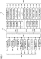
- FIGS. 1 and 2 illustrate an example configuration of a vehicle control system 10.
- the vehicle control system 10 is installed in a vehicle 11 (specifically an automatic four-wheeled vehicle).
- the vehicle 11 is switchable among manual driving, assisted driving, and autonomous driving.
- the manual driving refers to driving in which the vehicle travels by driver's operation (e.g., operation of an accelerator).
- the assisted driving refers to driving in which the vehicle travels with assistance of driver's operation.
- the autonomous driving refers to driving in which the vehicle travels without driver's operation.
- the vehicle control system 10 controls operation of the vehicle 11 by controlling a plurality of actuators 100 in the vehicle 11 in the autonomous driving or the assisted driving.
- an X-by-wire technology for electrical control is employed. Specifically, an operation of an accelerator pedal, an operation of a brake pedal, and an operation of a steering wheel are detected by sensors described later, and the actuators 100 (i.e., actuators 100 concerning driving control, braking control, and steering control) are controlled in response to control signals generated based on outputs of the sensors so that driving control, braking control, and steering control are performed.
- the actuators 100 i.e., actuators 100 concerning driving control, braking control, and steering control
- the actuators 100 individually actuate a plurality of vehicle-mounted devices (not shown) mounted on the vehicle 11.
- the actuators 100 include not only actuators 100 for actuating vehicle-mounted devices concerning basic operations of the vehicle 11 (e.g., driving, braking, and steering) but also actuators 100 for actuating vehicle-mounted devices not concerning basic operations of the vehicle 11 (so-called body-related devices).
- Examples of the vehicle-mounted devices include an engine, a transmission, an electric brake, an electric power steering, a brake lamp, a headlamp, an electric mirror, and an audio system. In the example illustrated in FIGS.
- examples of the actuators 100 are an actuator 101 for an electric power steering device, actuators 102, 103, 111, and 112 for electric brakes, actuators 104 and 113 for brake lamps, actuators 105 and 114 for headlamps, and actuators 107 and 115 for electric mirrors.
- the vehicle control system 10 includes a plurality of sensors 200, a communication unit 210, and a computation device 15.
- Each of the sensors 200 detects information for use in control of the actuators 100.
- examples of the sensors 200 are a plurality of cameras 201, a plurality of radars 202, a position sensor 203, a vehicle state sensor 204, a passenger state sensor 205, a steering angle sensor 206, a brake sensor 207, and an accelerator sensor 208.
- the cameras 201 have similar configurations.
- the cameras 201 capture images of an external environment of the vehicle 11 to thereby acquire image data on the external environment of the vehicle 11.
- Image data acquired by the cameras 201 is transmitted to the computation device 15 (specifically a central controller 300, the same hereinafter).
- the cameras 201 are an example of an imaging section for taking images of an external environment of the vehicle 11.
- the cameras 201 are monocular cameras having wide-angle lenses.
- the plurality of cameras 201 are disposed in the vehicle 11 such that an imaging area of the external environment of the vehicle 11 to be taken by the cameras 201 covers the entire surrounding of the vehicle 11.
- the cameras 201 are constituted by solid-state image sensors such as charge coupled devices (CCD) or complementary metal-oxide-semiconductors (CMOS).
- CCD charge coupled devices
- CMOS complementary metal-oxide-semiconductors
- the cameras 201 may be monocular cameras including normal lenses or stereo cameras.
- the radars 202 have similar configurations.
- the radars 202 detect an external environment of the vehicle 11. Specifically, the radars 202 transmits electric waves toward the external environment of the vehicle 11 and receive reflected waves from the eternal environment of the vehicle 11 to thereby detect the external environment of the vehicle 11. Detection results of radars 202 are transmitted to the computation device 15.
- the radars 202 are an example of a detector for detecting the external environment of the vehicle 11. The detector transmits detection waves toward the external environment of the vehicle 11 and receives reflected waves from the external environment of the vehicle 11 to thereby detect the external environment of the vehicle 11.
- the plurality of radars 202 are arranged on the vehicle 11 such that a detection area of the external environment of the vehicle 11 to be taken by the radars 202 covers the entire surrounding of the vehicle 11.
- the radars 202 may be millimeter-wave radars for transmitting millimeter waves, lidars (light detection and ranging) for transmitting and receiving laser light, infrared ray radars for transmitting and receiving infrared rays, or ultrasonic wave sensors for transmitting and receiving ultrasonic waves.
- the position sensor 203 detects a position (e.g., latitude and longitude) of the vehicle 11. For example, the position sensor 203 receives GPS information from a global positioning system and detects the position of the vehicle 11 based on the GPS information. The position of the vehicle 11 detected by the position sensor 203 is transmitted to the computation device 15.
- a position e.g., latitude and longitude
- the position sensor 203 receives GPS information from a global positioning system and detects the position of the vehicle 11 based on the GPS information.
- the position of the vehicle 11 detected by the position sensor 203 is transmitted to the computation device 15.
- the vehicle state sensor 204 detects a state (e.g., speed, acceleration, and yaw rate) of the vehicle 11.
- the vehicle state sensor 204 includes a vehicle speed sensor for detecting a speed of the vehicle 11, an acceleration sensor for detecting an acceleration of the vehicle 11, and a yaw rate sensor for detecting a yaw rate of the vehicle 11.
- the state of the vehicle 11 detected by the vehicle state sensor 204 is transmitted to the computation device 15.
- the passenger state sensor 205 detects a state of a passenger (e.g., physical condition, emotion, and physical behavior of a driver) on the vehicle 11.
- the passenger state sensor 205 includes an in-vehicle camera for taking an image of the passenger and a biometric sensor for detecting biometric information of the passenger.
- the state of the passenger detected by the passenger state sensor 205 is transmitted to the computation device 15.
- the steering angle sensor 206, the brake sensor 207, and the accelerator sensor 208 are examples of a driving operation sensor for detecting a driving operation to the vehicle 11.
- the steering angle sensor 206 detects a steering angle of a steering wheel of the vehicle 11.
- the brake sensor 207 detects a manipulated variable of a brake of the vehicle 11.
- the accelerator sensor 208 detects a manipulated variable of an accelerator of the vehicle 11.
- the driving operation detected by the driving operation sensor is transmitted to the computation device 15.
- the communication unit 210 communicates with an external device disposed outside the vehicle 11.
- the communication unit 210 receives, for example, communication information from other vehicles (not shown) located around the vehicle 11 and traffic information from a navigation system (not shown).
- the information received by the communication unit 210 is transmitted to the computation device 15.
- the computation device 15 controls operation of the actuators 100 based on, for example, outputs of the sensors 200 on the vehicle 11 and information from outside the vehicle. For example, the computation device 15 determines a target path that is a path on which the vehicle 11 is to travel, determines a target motion that is a motion of the vehicle 11 necessary for traveling on the target route, and controls operation of the actuators 100 such that motion of the vehicle 11 is the target motion.
- the computation device 15 includes the central controller 300, and a plurality of zone controllers 400.
- the computation device 15 includes one central controller 300, two zone controllers 401 and 402, and nine zone controllers 501 through 505 and 511 through 514.
- Each of the central controller 300 and the zone controllers 400 is constituted by an electronic control unit (ECU) including, for example, one or more processors, and one or more memories for storing programs and data for operating the one or more processors.
- ECU electronice control unit
- the two zone controllers 401 and 402 are connected to the central controller 300. As illustrated in FIG. 2 , the zone controller 401 is disposed in a center portion of the right side of the vehicle 11, and the zone controller 402 is disposed in a center portion of the left side of the vehicle 11.
- Five zone controllers 501 through 505 and the actuator 107 of the electric mirror are connected to the zone controller 401.
- the five actuators 101 through 105 are respectively connected to the five zone controllers 501 through 505.
- Four zone controllers 511 through 514 and the actuator 115 of the electric mirror are connected to the zone controller 402.
- the four actuators 111 through 114 are respectively connected to the four zone controllers 511 through 514.
- signal lines connecting the central controller 300 to the zone controllers 400 and a signal line connecting two zone controllers 400 are communication cables of Ethernet (registered trademark)
- signal lines connecting the central controller 300 to the actuators 100 and signal lines connecting the zone controllers 400 to the actuators 100 are communication cables of controller area network (CAN).
- CAN controller area network
- Each of the zone controllers 501 through 505 and 511 through 514 has the function of performing protocol conversion between Ethernet (registered trademark) and CAN.
- the central controller 300 receives outputs of the sensors 200 on the vehicle 11 and information from the outside of the vehicle and generates a plurality of control signals for controlling the actuators 100.
- the central controller 300 outputs a plurality of control signals.
- the central controller 300 is an example of a first controller.
- the central controller 300 recognizes an external environment of the vehicle 11 based on outputs of the cameras 201 and the radars 202, and generates one or more candidate routes based on the recognized external environment of the vehicle 11.
- the candidate routes are routes on which the vehicle 11 is allowed to travel, and candidates of a target route.
- the central controller 300 recognizes a behavior (e.g., speed, acceleration, and yaw rate) of the vehicle 11 based on an output of the vehicle state sensor 204. For example, the central controller 300 recognizes a behavior of the vehicle 11 from the output of the vehicle state sensor 204 using a leaning model generated by deep learning.
- a behavior e.g., speed, acceleration, and yaw rate
- the central controller 300 recognizes a behavior of a passenger (e.g., physical condition, emotion, and physical behavior of a driver) based on an output of the passenger state sensor 205. For example, the central controller 300 recognizes a behavior of a passenger (especially a driver) from an output of the passenger state sensor 205 using a leaning model generated by deep learning.
- a behavior of a passenger e.g., physical condition, emotion, and physical behavior of a driver
- the central controller 300 recognizes a behavior of a passenger (especially a driver) from an output of the passenger state sensor 205 using a leaning model generated by deep learning.
- the central controller 300 recognizes a driving operation applied to the vehicle 11 based on outputs of the steering angle sensor 206, the brake sensor 207, and the accelerator sensor 208.
- the central controller 300 selects a candidate route to be a target route from the one or more candidate routes generated as described above, based on the recognized behavior of the vehicle 11 and the driving operation applied to the vehicle 11. For example, the central controller 300 selects a candidate route for which the driver feels most comfortable from the plurality of candidate routes. Then, the central controller 300 determines a target motion based on the candidate route selected as the target route.
- the central controller 300 generates a control signal for achieving the target motion. For example, the central controller 300 derives a target driving force, a target braking force, and a target steering amount that are a driving force, a braking force, and a steering amount for achieving a target motion.
- the central controller 300 generates a driving control signal showing a target driving force, a braking control signal showing a target braking force, and a steering control signal showing a target steering amount.
- the central controller 300 outputs a control signal.
- Each of the plurality of zone controllers 400 is provided in a predetermined zone of the vehicle 11.
- Each of the zone controllers 400 is disposed on a signal path between the central controller 300 and a corresponding one of the actuators 100.
- one or more zone controllers 400 are provided on signal paths between the central controller 300 and one of the actuators 100.
- two zone controllers 401 and 501 are provided on a signal path between the central controller 300 and the actuator 101 of the electric power steering.
- Each of the zone controllers 400 relays a signal. With this configuration, a control signal output from the central controller 300 is supplied to the actuator 100 by way of one or more zone controllers 400 so that operation of the actuator 100 is controlled.
- the zone controllers 400 disposed on signal paths between the central controller 300 and actuators (not shown) of the engine and the transmission relay control signals output from the central controller 300 to the actuators of the engine and the transmission.
- the actuators of the engine and the transmission actuate the engine and the transmission based on a target driving force shown by a driving control signal. Accordingly, a driving force of the vehicle 11 is controlled to be a target driving force.
- the zone controllers 401 and 502 disposed on a signal path between the central controller 300 and the actuator 102 of the electric brake relay a braking control signal output from the central controller 300 to the actuator 102.
- the actuator 102 actuates the electric brake based on a target braking force shown by the braking control signal. Accordingly, the braking force of the electric brake is controlled to be a target braking force.
- the actuator 101 actuates an electric power steering based on a target steering amount shown by the steering control signal. Accordingly, the steering amount of the vehicle 11 is controlled to be a target steering amount.
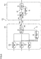
- the central controller 300 and the zone controllers 400 will now be described in detail. The following description is directed to a combination of the central controller 300 and one of the zone controllers 400.
- the vehicle control system 10 includes at least one (one in this example) signal line 600 connecting the central controller 300 (first controller) to the zone controller 400 (second controller).
- the signal line 600 is a communication cable of Ethernet (registered trademark).
- the central controller 300 includes three or more computation units 30, a determination unit 40, and an output unit 50.
- the central controller 300 includes three computation units 30 (specifically a first computation unit 31, a second computation unit 32, and a third computation unit 33).
- Each of the computation units 30 supplies a first control signal to the output unit 50. Accordingly, a plurality of first control signals are supplied from the computation units 30 to the output unit 50. Specifically, the computation units 30 obtain target outputs of the actuators 100 based on, for example, information detected by the sensors 200, and output first control signals showing the obtained target outputs of the actuators 100.
- the first control signals are signals for controlling the actuators 100.
- each of the first control signals shows a target output (e.g., target controlled variable) of a corresponding one of the actuators 100.
- target outputs include a target driving force, a target braking force, and a target steering amount.
- the target outputs shown by the first control signals are of the same type, but are different from one another in at least one of information used for deriving the target outputs (e.g., information detected by the sensors 200) and content of the deriving process of the target outputs (e.g., mathematical expression).
- information used for deriving the target outputs e.g., information detected by the sensors 200
- content of the deriving process of the target outputs e.g., mathematical expression
- one of the three first control signals shows a target steering amount derived based on a steering angle of the steering wheel of the vehicle 11 detected by the steering angle sensor 206.
- Another first control signal shows a target steering amount derived based on a rotation angle of an electric motor (not shown) of the electric power steering detected by a resolver (not shown) and a first operational expression (operational expression for deriving a target steering amount based on the rotation angle of the electric motor).
- the other first control signal shows a target steering amount derived based on the rotation angle of the electric motor of the electric power steering detected by the resolver and a second operational expression (operational expression for deriving a target steering amount based on the rotation angle of the electric motor) different from the first operational expression.
- the target outputs obtained by the computation units 30 are of the same type, but are different from one another in at least one of information used for deriving the target outputs in the corresponding computation units 30 (e.g., information detected by the sensors 200) and contents of the deriving process (e.g., mathematical expression) of the target outputs in the computation units 30.
- information used for deriving the target outputs in the corresponding computation units 30 e.g., information detected by the sensors 200
- contents of the deriving process e.g., mathematical expression
- the first computation unit 31 obtains a target steering amount based on a steering angle of the steering wheel of the vehicle 11 detected by the steering angle sensor 206.
- the second computation unit 32 obtains a target steering amount based on information detected by the resolver (not shown) and the first operational expression.
- the third computation unit 33 obtains a target steering amount based on information detected by the resolver and the second operational expression.
- each of the computation units 30 is constituted by a computation core (processor) that performs predetermined computation.
- the determination unit 40 assigns a target output shown by a first control signal supplied from each of the computation units 30 with a weight based on the degree of reliability of this first control signal, and performs a majority vote of target outputs.
- the determination unit 40 previously stores weights based on the degrees of reliability of the first control signals supplied from the computation units 30.
- the determination unit 40 receives the first control signals supplied from the computation units 30, and assigns the target outputs shown by the first control signals with weights based on the degrees of reliability of the first control signals.
- the weight based on the degree of reliability of this first control signal increases.
- the number of votes based on the degree of reliability of this first control signal may be assigned as a weight. For example, as the degree of reliability of a first control signal increases, the number of votes based on the degree of reliability of this first control signal increases.
- the determination unit 40 stores weight information (information table) showing weights based on the degrees of reliability of a plurality of first control signals.
- the determination unit 40 selects a weight corresponding to each of the first control signals supplied from the computation units 30 from the weight information, and assigns the selected weight to a target output shown by each of the first control signals.
- the determination unit 40 determines which one of the weighted target outputs is a majority, and outputs a majority vote signal showing which target output is a majority, to the output unit 50.
- the determination unit 40 is constituted by a computation core (processor) for performing predetermined computation, and a memory that stores programs and data for operating the computation core. Operation of the determination unit 40 will be specifically described later.
- the output unit 50 outputs a second control signal based on first control signals supplied from the computation units 30 and a result of a majority vote of target outputs by the determination unit 40.
- the second control signals are signals for controlling the actuators 100.
- the second control signals show target outputs (e.g., target controlled variables) of the actuators 100.
- the target outputs shown by the second control signals are of the same type as target outputs shown by the first controllers.
- the target outputs shown by the second control signals are also target steering amounts.
- the output unit 50 selects a first control signal showing a target output determined to be a majority by the determination unit 40 from the first control signals supplied from the computation units 30, and outputs the selected first control signal as a second control signal.
- an output terminal of the output unit 50 is electrically connected to one end of the signal line 600.
- the central controller 300 includes a connector 30a corresponding to the output terminal of the output unit 50.
- the output terminal of the output unit 50 is electrically connected to the connector 30a by an internal wiring 30b.
- One end of the signal line 600 is connected to the connector 30a.
- the output unit 50 is constituted by a computation core (processor) for performing predetermined computation. Operation of the output unit 50 will be specifically described later.
- the three computation units 30 (the first computation unit 31, the second computation unit 32, and the third computation unit 33), the determination unit 40, and the output unit 50 in the central controller 300 constitute a safety architecture 70 of 1-out-of-3 channel (1oo3).
- the safety architecture 70 is fail operational (control continuation type).
- the zone controller 400 is disposed on a signal path between the central controller 300 and a corresponding one of the actuators 100.
- the zone controller 400 includes an input/output control unit 61, a diagnosis unit 62, and an output unit 63.
- the input/output control unit 61 performs predetermined input/output processing (e.g., protocol conversion) on the second control signal output from the output unit 50.
- the input/output control unit 61 supplies the second control signal subjected to the input/output processing to the output unit 50.
- the diagnosis unit 62 performs an abnormality diagnosis of the input/output control unit 61. Based on a diagnosis result of the input/output control unit 61 by the diagnosis unit 62, the output unit 63 is switched between a first state of outputting the second control signal supplied from the input/output control unit 61 and a second state of outputting a predetermined output signal (fixed value).
- the output unit 63 is switched to the first state in a case where the input/output control unit 61 has no abnormality, and switched to the second state in a case where the input/output control unit 61 has abnormality.
- each of the input/output control unit 61, the diagnosis unit 62, and the output unit 63 is constituted by a computation core (processor) for performing predetermined computation.
- an input terminal of the input/output control unit 61 is electrically connected to the other end of the signal line 600.
- the zone controller 400 includes a connector 40a corresponding to the input terminal of the input/output control unit 61.
- the input terminal of the input/output control unit 61 is electrically connected to the connector 40a by an internal wiring 40b.
- the input/output control unit 61, the diagnosis unit 62, and the output unit 63 constitute a safety architecture 80 of 1-out-of-1 channel with diagnostics (1oo1D).
- the safety architecture 80 is fail safe (control stop type).
- the determination unit 40 outputs a majority vote signal showing that the target steering amount of "rotate counterclockwise by 10°” is a majority.
- the output unit 50 selects the first control signal showing the target steering amount of "rotate counterclockwise by 10°" (i.e., one of the first control signals supplied from the first computation unit 31 and the second computation unit 32) from the first control signals supplied from the first computation unit 31, the second computation unit 32, and the third computation unit 33, and outputs the selected first control signal as a second control signal.
- the second control signal can be output in consideration of the degrees of reliability of a plurality of first control signals. Accordingly, high reliability in controlling the actuators 100 can be maintained. Thus, reliability of the fail operational function can be enhanced.
- the weights based on the degrees of reliability of a plurality of first control signals may vary depending on the scene of the vehicle 11.
- the determination unit 40 may store weight information (information table) showing weights based on the degrees of reliability of first control signals for each scene of the vehicle 11.
- the scene of the vehicle 11 include a scene in which the vehicle 11 travels in the daytime, a scene in which the vehicle 11 travels at night, a scene in which the vehicle 11 travels at low speed, a scene in which the vehicle 11 travels at high speed, a scene in which the vehicle 11 follows another vehicle in front, a scene in which the vehicle is put in a garage, and a combination of these scenes.
- These scenes can be estimated from, for example, information detected by the sensors 200 and an external environment of the vehicle 11 recognized from the information detected by the sensors 200.
- the second control signal can be output in consideration of the degrees of reliability of the plurality of first control signals that vary depending on the scene of the vehicle 11. Accordingly, high reliability in controlling the actuators 100 can be maintained. Thus, reliability of the fail operational function can be enhanced.
- the output unit 50 may be configured to generate a second control signal by synthesizing first control signals supplied from the computation units 30 based on a result of a majority vote of target outputs by the determination unit 40 and the weights based on the degrees of reliability of the first control signals.
- the determination unit 40 receives the first control signals supplied from the computation units 30, and assigns target outputs shown by the first control signals with weights based on the degrees of reliability of the first control signals. Next, the determination unit 40 determines to which group a target output shown by each first control signal belongs among a plurality of predetermined groups (groups of target outputs). The determination unit 40 determines which group of target groups is a majority among the plurality of groups based on the sum of the weights assigned to target outputs belonging to the groups, and outputs, to the output unit 50, a majority vote signal showing which group of target outputs is a majority. To each of the first control signals, the number of votes based on the degree of reliability of this first control signal may be assigned as a weight. For example, as the degree of reliability of a first control signal increases, the number of votes based on the degree of reliability of this first control signal increases.
- the output unit 50 selects one or more first control signals showing target outputs belonging to the group determined as a group to which target outputs as a majority belongs by the determination unit 40, from the plurality of first control signals supplied from the computation units 30. Then, the output unit 50 outputs, as a second control signal, a first control signal having the highest degree of reliability among the selected one or more first control signals.
- the output unit 50 stores reliability information (information table) showing the degrees of reliability of the first control signals.
- the output unit 50 selects a first control signal having highest degree of reliability among one or more first control signals with reference to the reliability information, and outputs the selected first control signal as a second control signal.
- target outputs shown by the first control signals are target steering amounts.
- a group of "target steering amount showing counterclockwise rotation” and a group of “target steering amount showing clockwise rotation” are previously defined.
- the first control signal supplied from the computation unit 31 shows a target steering amount of "rotate clockwise by 50°
- the first control signal supplied from the second computation unit 32 shows a target steering amount of "rotate counterclockwise by 10°
- the first control signal supplied from the third computation unit 33 shows a target steering amount of "rotate counterclockwise by 15°
- "five votes" of the first control signal from the first computation unit 31 are assigned to the target steering amount of "rotate clockwise by 50°
- “four votes” of the first control signal from the second computation unit 32 are assigned to the target steering amount of "rotate counterclockwise by 10°
- "two votes" of the first control signal from the third computation unit 33 are assigned to the target steering amount of "rotate counterclockwise by 15°.”
- the sum of votes of target steering amounts belonging to the group of "target steering amount showing clockwise rotation” is "five votes” and the sum of votes of target steering amounts belonging to the group of “target steering amount showing counterclockwise rotation” is “six.”
- the determination unit 40 outputs a majority vote signal showing that target steering amounts belonging to the group of "target steering amount showing counterclockwise rotation” is a majority.
- the output unit 50 selects the first control signal showing the target steering amount belonging to the group of "target steering amount showing counterclockwise rotation” (i.e., first control signals supplied from the second computation unit 32 and the third computation unit 33) from the first control signals supplied from the first computation unit 31, the second computation unit 32, and the third computation unit 33.
- the output unit 50 selects the first control signal from the second computation unit 32 having the largest number of assigned votes (example of reliability) (i.e., first control signal showing the target steering amount of "rotate counterclockwise by 10°") from the first control signals supplied from the second computation unit 32 and the third computation unit 33, and outputs the selected first control signal as a second control signal.
- the second control signal is generated by synthesizing first control signals supplied from the computation units 30 based on a result of the majority vote of target outputs by the determination unit 40 and the weights based on the degrees of reliability of the first control signals
- the second control signal can be generated in consideration of the degrees of reliability of the first control signals. Accordingly, high reliability in controlling the actuators 100 can be maintained. Thus, reliability of the fail operational function can be enhanced.
- the output unit 50 may be configured as follows. First, the output unit 50 selects one or more first control signals showing target outputs belonging to the group determined as a group to which a majority of target outputs belongs by the determination unit 40, from the first control signals supplied from the computation units 30. Then, the output unit 50 performs weighted averaging on each of the selected one or more first control signals based on the degree of reliability of this first control signal. To each of the first control signals, a weighting factor (smaller than one and larger than zero) based on the degree of reliability of this first control signal may be assigned as a weight. For example, as the degree of reliability of a first control signal, the weighting factor based on the degree of reliability of this first control signal increases.
- the determination unit 50 stores weighting factor information (information table) showing weighting factors based on the degrees of reliability of a plurality of first control signals. Then, the output unit 50 selects a weighting factor corresponding to each of the one or more first control signals from the weighting factor information, and performs weighted averaging of one or more first control signals using the selected one or more weighting factors. Thereafter, the output unit 50 outputs a second control signal showing a target output derived by the weighted averaging.
- weighting factor information information table
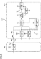
- one or more of the computation units 30 may be provided in the central controller 300 (first controller). Another one or more of the computation units 30 may be provided in the zone controller 400 (second controller).
- the first computation unit 31 and the second computation unit 32 of the three computation units 30 are disposed in the central controller 300, and the third computation unit 33 is disposed in the zone controller 400.
- the determination unit 40 and the output unit 50 are disposed in the zone controller 400.
- two signal lines 600 are provided to connect the central controller 300 to the zone controller 400.
- output terminals of the two computation units 30 (specifically the first computation unit 31 and the second computation unit 32) are respectively electrically connected to two connectors 30a of two internal wirings 30b to be thereby electrically connected to ends of the two signal lines 600 at one side.
- two of three input terminals of the output unit 50 are electrically connected to the two connectors 40a by the two internal wirings 40b to be thereby electrically connected to ends of the signal lines 600 at the other side.
- the other input terminal of the three input terminals of the output unit 50 is electrically connected to an output terminal of the third computation unit 33 by an internal wiring.
- the first computation unit 31 of the three computation units 30 is disposed in the central controller 300, and the second computation unit 32 and the third computation unit 33 are disposed in the zone controller 400.
- the determination unit 40 and the output unit 50 are disposed in the zone controller 400.
- the first computation unit 31 is electrically connected to the connector 30a by the internal wiring 30b to be thereby connected to one end of the signal line 600.
- the zone controller 400 one of three input terminals of the output unit 50 is electrically connected to the connector 40a by the internal wiring 40b to be thereby electrically connected to the other end of the signal line 600.
- the other two input terminals of the output unit 50 are electrically connected to output terminals of two computation units 30 (specifically the second computation unit 32 and the third computation unit 33) by two internal wirings.
- the computation units 30 are disposed in the central controller 300 (first controller) and another one or more of the computation units 30 are disposed in the zone controller 400 (second controller), even when supply of first control signals from the computation units 30 of the central controller 300 stops because of an error in the central controller 300, control of the actuators 100 can be continued by using first control signals supplied from the computation units 30 in the zone controller 400. As a result, reliability of the fail operational function can be enhanced.
- the computation units 30 may be disposed in the central controller 300 (first controller).
- the determination unit 40 and the output unit 50 may be disposed in the zone controller 400 (second controller).
- the central controller 300 output terminals of the computation units 30 are electrically connected to ends of the signal lines 600 at one side.
- the central controller 300 includes three connectors 30a respectively corresponding to the three computation units 30.
- the output terminals of the three computation units 30 are respectively electrically connected to the three connectors 30a by three internal wirings 30b. Ends of the three signal lines 600 at one side are respectively connected to the three connectors 30a.
- a plurality of input terminals of the output unit 50 are electrically connected to ends of the signal lines 600 at the other side.
- the zone controller 400 includes three connectors 40a respectively corresponding to three input terminals of the output unit 50.
- the three input terminals of the output unit 50 are respectively electrically connected to the three connectors 40a by three internal wirings 40b.
- the ends of the three signal lines 600 at the other side are respectively connected to the three connectors 40a.
- the three computation units 30 (the first computation unit 31, the second computation unit 32, and the third computation unit 33) in the central controller 300 and the diagnosis unit 40 and the output unit 50 in the zone controller 400 constitute a safety architecture 70 of 1oo3 (1-out-of-3 channel).
- the central controller 300 includes four or more computation units 30.
- the output unit 50 outputs a second control signal based on first control signals supplied from the four or more computation units 30 and a result of a majority vote of target outputs by the determination unit 40.
- a plurality of first control signals can be supplied from the central controller 300 to the zone controller 400 through the signal lines 600. Accordingly, survivability to a communication error (e.g., blackout) between the central controller 300 and the zone controller 400 can be enhanced, as compared to a case where a single first control signal is supplied from the central controller 300 to the zone controller 400 through a single signal line. That is, a failure in continuing control of the actuators 100 caused by communication errors between the central controller 300 and the zone controller 400 is less likely to occur. As a result, continuity of the fail operational function can be enhanced.
- a communication error e.g., blackout
- At least two of the signal lines 600 connecting the central controller 300 (the first controller) to the zone controller 400 (the second controller) preferably have different types of resistance.
- the signal lines 600 include one or more signal lines 600 having resistance (mechanical resistance) to a mechanical external force such as vibrations and impacts. If the signal lines 600 do not include a signal line 600 having resistance (electrical resistance) to an electrical external force such as noise, the electrical external force might cause communication errors in all the signal lines. On the other hand, the signal lines 600 include signal lines 600 having electrical resistance as well as signal lines 600 having mechanical resistance, electrical errors are less likely to occur in all the signal lines 600 because of an electrical external force.
- At least two of the signal lines 600 connecting the central controller 300 (the first controller) to the zone controller 400 (the second controller) are preferably of different types. Examples of these types of the signal lines 600 include diameters of the signal lines 600, materials for the signal lines 600, and structures of the signal lines 600.
- the two signal lines 600 are allowed to have different types of resistance. Accordingly, survivability to a communication error between the central controller 300 and the zone controller 400 can be enhanced, as compared to the case where all the signal lines 600 have the same type of resistance. Accordingly, continuity of the fail operational function can be enhanced.
- mechanical resistance of the former signal line 600 is higher than mechanical resistance of the latter signal line 600.
- mechanical strength of the former signal line 600 is higher than mechanical resistance of the latter signal line 600.
- electrical resistance of the former signal line 600 is higher than electrical resistance of the latter signal line 600.
- At least two of the signal lines 600 connecting the central controller 300 (the first controller) to the zone controller 400 (the second controller) are preferably separated from each other.
- the risk of occurrence of communication errors (especially blackout caused by disconnection) in all the signal lines 600 by an external force (especially mechanical external force) can be reduced.
- continuity of the fail operational function can be enhanced.
- one signal line 600 may reach the zone controller 400 from the central controller 300 by way of the right side of the vehicle 11 with the other signal line 600 reaching the zone controller 400 from the central controller 300 by way of the left side of the vehicle 11.
- FIG. 7 illustrates an example specific configuration of the central controller 300 and the zone controller 400.
- the central controller 300 is constituted by an electronic control unit (ECU).
- the electronic control unit includes one or more chips A.
- Each chip A includes one or more cores B.
- the core B includes a processor P and a memory M. That is, the central controller 300 includes one or more processors P and one or more memories M.
- the memory M stores programs and information for operating the processor.
- the memory M stores, for example, a module as software capable of being executed by the processor P and data showing a model to be used in processing of the processor P.
- Functions of units of the central controller 300 described above are implemented by execution of modules stored in the memory M by the processor P.
- the configuration of the zone controller 400 is similar to the configuration of the central controller 300.
- the output unit 50 may be configured to output N (where N is an integer less than M) second control signals based on M (where M is an integer of 3 or more) first control signals.
- M computation units 30, the determination unit 40, and the output unit 50 may constitute a safety architecture 70 of M-out-of-N channel (MooN).
- the technique disclosed here is useful as a vehicle control system.
Landscapes
- Engineering & Computer Science (AREA)
- Automation & Control Theory (AREA)
- Mechanical Engineering (AREA)
- Human Computer Interaction (AREA)
- Transportation (AREA)
- Theoretical Computer Science (AREA)
- Quality & Reliability (AREA)
- Physics & Mathematics (AREA)
- General Engineering & Computer Science (AREA)
- General Physics & Mathematics (AREA)
- Control Of Driving Devices And Active Controlling Of Vehicle (AREA)
- Steering Control In Accordance With Driving Conditions (AREA)
Applications Claiming Priority (2)
| Application Number | Priority Date | Filing Date | Title |
|---|---|---|---|
| JP2019140231A JP7346980B2 (ja) | 2019-07-30 | 2019-07-30 | 車両制御システム |
| PCT/JP2020/028504 WO2021020294A1 (fr) | 2019-07-30 | 2020-07-22 | Système de commande de véhicule |
Publications (3)
| Publication Number | Publication Date |
|---|---|
| EP4005892A1 true EP4005892A1 (fr) | 2022-06-01 |
| EP4005892A4 EP4005892A4 (fr) | 2022-08-24 |
| EP4005892B1 EP4005892B1 (fr) | 2024-01-17 |
Family
ID=74230308
Family Applications (1)
| Application Number | Title | Priority Date | Filing Date |
|---|---|---|---|
| EP20847609.3A Active EP4005892B1 (fr) | 2019-07-30 | 2020-07-22 | Système de commande de véhicule |
Country Status (5)
| Country | Link |
|---|---|
| US (1) | US20220212683A1 (fr) |
| EP (1) | EP4005892B1 (fr) |
| JP (1) | JP7346980B2 (fr) |
| CN (1) | CN114245777B (fr) |
| WO (1) | WO2021020294A1 (fr) |
Families Citing this family (2)
| Publication number | Priority date | Publication date | Assignee | Title |
|---|---|---|---|---|
| JP7346980B2 (ja) * | 2019-07-30 | 2023-09-20 | マツダ株式会社 | 車両制御システム |
| DE102023117791A1 (de) * | 2023-07-06 | 2025-01-09 | HELLA GmbH & Co. KGaA | Steuergerät für ein Kontrollsystem eines Kraftfahrzeugs, Kontrollsystem für ein Kraftfahrzeug und Verfahren zum Betrieb eines Kontrollsystems |
Family Cites Families (20)
| Publication number | Priority date | Publication date | Assignee | Title |
|---|---|---|---|---|
| JPS5014987A (fr) * | 1973-06-13 | 1975-02-17 | ||
| JPH01164621A (ja) * | 1987-12-18 | 1989-06-28 | Diesel Kiki Co Ltd | 車両用空調制御装置 |
| US5084878A (en) * | 1988-10-24 | 1992-01-28 | Hitachi, Ltd. | Fault tolerant system employing majority voting |
| JP3279004B2 (ja) * | 1993-10-15 | 2002-04-30 | 株式会社日立製作所 | 冗長資源の管理方法及びそれを用いた分散型フォールトトレラントコンピュータシステム |
| JP4848027B2 (ja) | 2004-01-30 | 2011-12-28 | 日立オートモティブシステムズ株式会社 | 車両制御装置 |
| JP4478037B2 (ja) | 2004-01-30 | 2010-06-09 | 日立オートモティブシステムズ株式会社 | 車両制御装置 |
| JP4740038B2 (ja) * | 2006-05-30 | 2011-08-03 | 富士重工業株式会社 | 画像処理装置 |
| CN101811515B (zh) * | 2009-12-18 | 2011-12-14 | 江苏长江环境科技工程有限公司 | 用于汽车主动转向系统的控制装置 |
| WO2012077204A1 (fr) | 2010-12-08 | 2012-06-14 | トヨタ自動車 株式会社 | Dispositif d'aide à la conduite |
| JP2014048702A (ja) * | 2012-08-29 | 2014-03-17 | Honda Elesys Co Ltd | 画像認識装置、画像認識方法、及び画像認識プログラム |
| FR3034882B1 (fr) * | 2015-04-07 | 2018-12-07 | Valeo Equipements Electriques Moteur | Procede d'implementation d'une fonction d'un vehicule automobile conforme a des niveaux asil standards, systeme correspondant et vehicule automobile comprenant un tel systeme |
| JP6611664B2 (ja) | 2016-04-26 | 2019-11-27 | 三菱電機株式会社 | 自動運転制御装置および自動運転制御方法 |
| EP3467606B1 (fr) * | 2016-05-30 | 2022-07-20 | Kubota Corporation | Véhicule de travail autonome |
| DE102017210955A1 (de) * | 2017-06-28 | 2019-01-17 | Volkswagen Aktiengesellschaft | Verfahren, vorrichtung und computerlesbares speichermedium mit instruktionen zum auflösen einer redundanz von zwei oder mehr redundanten modulen |
| CN107703935A (zh) * | 2017-09-12 | 2018-02-16 | 安徽胜佳和电子科技有限公司 | 多个数据权重融合进行避障的方法、存储装置及移动终端 |
| US10933882B2 (en) * | 2017-12-27 | 2021-03-02 | Micron Technology, Inc. | Determination of reliability of vehicle control commands using a voting mechanism |
| CN109109863B (zh) * | 2018-07-28 | 2020-06-16 | 华为技术有限公司 | 智能设备及其控制方法、装置 |
| CN108983204B (zh) * | 2018-08-22 | 2022-07-05 | 上海交通大学 | 一种无钥匙进入和无钥匙启动系统定位方法 |
| JP7346980B2 (ja) * | 2019-07-30 | 2023-09-20 | マツダ株式会社 | 車両制御システム |
| US12122332B2 (en) * | 2021-01-04 | 2024-10-22 | The Boeing Company | Systems and methods for automated in-situ swapping of batteries for electric vehicles |
-
2019
- 2019-07-30 JP JP2019140231A patent/JP7346980B2/ja active Active
-
2020
- 2020-07-22 WO PCT/JP2020/028504 patent/WO2021020294A1/fr not_active Ceased
- 2020-07-22 US US17/630,936 patent/US20220212683A1/en not_active Abandoned
- 2020-07-22 EP EP20847609.3A patent/EP4005892B1/fr active Active
- 2020-07-22 CN CN202080054677.7A patent/CN114245777B/zh active Active
Also Published As
| Publication number | Publication date |
|---|---|
| EP4005892A4 (fr) | 2022-08-24 |
| JP2021020649A (ja) | 2021-02-18 |
| JP7346980B2 (ja) | 2023-09-20 |
| EP4005892B1 (fr) | 2024-01-17 |
| CN114245777A (zh) | 2022-03-25 |
| CN114245777B (zh) | 2024-05-10 |
| WO2021020294A1 (fr) | 2021-02-04 |
| US20220212683A1 (en) | 2022-07-07 |
Similar Documents
| Publication | Publication Date | Title |
|---|---|---|
| EP4420948B1 (fr) | Système matériel redondant pour véhicules autonomes | |
| CN110562171B (zh) | 汽车电控系统及汽车 | |
| US11378954B2 (en) | Multi-processor SoC system | |
| EP4005890B1 (fr) | Système de commande de véhicule | |
| CN114097258B (zh) | 网络集线装置 | |
| EP4005892B1 (fr) | Système de commande de véhicule | |
| EP3862836B1 (fr) | Système de commande utilisant deux calculateurs pour régulation de vitesse véhicle | |
| CN114174141B (zh) | 车辆控制系统 | |
| EP4012981B1 (fr) | Système de réseau dans un véhicule | |
| CN114080794A (zh) | 车载网络系统 | |
| JP2021135809A (ja) | 車載機器制御装置 | |
| EP3998745B1 (fr) | Dispositif concentrateur de réseau | |
| EP4005891B1 (fr) | Système de commande de véhicule | |
| CN121019608B (zh) | 一种车辆组件控制方法、车辆、存储介质及程序产品 | |
| CN121062623A (zh) | 一种基于光纤通信的多系统融合方法、架构及系统 | |
| CN120035959A (zh) | 车载通信系统、控制装置及电气装置 |
Legal Events
| Date | Code | Title | Description |
|---|---|---|---|
| STAA | Information on the status of an ep patent application or granted ep patent |
Free format text: STATUS: THE INTERNATIONAL PUBLICATION HAS BEEN MADE |
|
| PUAI | Public reference made under article 153(3) epc to a published international application that has entered the european phase |
Free format text: ORIGINAL CODE: 0009012 |
|
| STAA | Information on the status of an ep patent application or granted ep patent |
Free format text: STATUS: REQUEST FOR EXAMINATION WAS MADE |
|
| 17P | Request for examination filed |
Effective date: 20220224 |
|
| AK | Designated contracting states |
Kind code of ref document: A1 Designated state(s): AL AT BE BG CH CY CZ DE DK EE ES FI FR GB GR HR HU IE IS IT LI LT LU LV MC MK MT NL NO PL PT RO RS SE SI SK SM TR |
|
| A4 | Supplementary search report drawn up and despatched |
Effective date: 20220727 |
|
| RIC1 | Information provided on ipc code assigned before grant |
Ipc: B60R 16/02 20060101ALI20220722BHEP Ipc: G06F 11/18 20060101ALI20220722BHEP Ipc: B60W 50/023 20120101AFI20220722BHEP |
|
| DAV | Request for validation of the european patent (deleted) | ||
| DAX | Request for extension of the european patent (deleted) | ||
| STAA | Information on the status of an ep patent application or granted ep patent |
Free format text: STATUS: EXAMINATION IS IN PROGRESS |
|
| 17Q | First examination report despatched |
Effective date: 20230510 |
|
| GRAP | Despatch of communication of intention to grant a patent |
Free format text: ORIGINAL CODE: EPIDOSNIGR1 |
|
| STAA | Information on the status of an ep patent application or granted ep patent |
Free format text: STATUS: GRANT OF PATENT IS INTENDED |
|
| GRAS | Grant fee paid |
Free format text: ORIGINAL CODE: EPIDOSNIGR3 |
|
| INTG | Intention to grant announced |
Effective date: 20231114 |
|
| GRAA | (expected) grant |
Free format text: ORIGINAL CODE: 0009210 |
|
| STAA | Information on the status of an ep patent application or granted ep patent |
Free format text: STATUS: THE PATENT HAS BEEN GRANTED |
|
| AK | Designated contracting states |
Kind code of ref document: B1 Designated state(s): AL AT BE BG CH CY CZ DE DK EE ES FI FR GB GR HR HU IE IS IT LI LT LU LV MC MK MT NL NO PL PT RO RS SE SI SK SM TR |
|
| REG | Reference to a national code |
Ref country code: GB Ref legal event code: FG4D |
|
| REG | Reference to a national code |
Ref country code: DE Ref legal event code: R096 Ref document number: 602020024621 Country of ref document: DE |
|
| REG | Reference to a national code |
Ref country code: CH Ref legal event code: EP |
|
| REG | Reference to a national code |
Ref country code: IE Ref legal event code: FG4D |
|
| REG | Reference to a national code |
Ref country code: LT Ref legal event code: MG9D |
|
| REG | Reference to a national code |
Ref country code: NL Ref legal event code: MP Effective date: 20240117 |
|
| REG | Reference to a national code |
Ref country code: AT Ref legal event code: MK05 Ref document number: 1650365 Country of ref document: AT Kind code of ref document: T Effective date: 20240117 |
|
| PG25 | Lapsed in a contracting state [announced via postgrant information from national office to epo] |
Ref country code: NL Free format text: LAPSE BECAUSE OF FAILURE TO SUBMIT A TRANSLATION OF THE DESCRIPTION OR TO PAY THE FEE WITHIN THE PRESCRIBED TIME-LIMIT Effective date: 20240117 |
|
| PG25 | Lapsed in a contracting state [announced via postgrant information from national office to epo] |
Ref country code: NL Free format text: LAPSE BECAUSE OF FAILURE TO SUBMIT A TRANSLATION OF THE DESCRIPTION OR TO PAY THE FEE WITHIN THE PRESCRIBED TIME-LIMIT Effective date: 20240117 |
|
| PG25 | Lapsed in a contracting state [announced via postgrant information from national office to epo] |
Ref country code: IS Free format text: LAPSE BECAUSE OF FAILURE TO SUBMIT A TRANSLATION OF THE DESCRIPTION OR TO PAY THE FEE WITHIN THE PRESCRIBED TIME-LIMIT Effective date: 20240517 |
|
| PG25 | Lapsed in a contracting state [announced via postgrant information from national office to epo] |
Ref country code: LT Free format text: LAPSE BECAUSE OF FAILURE TO SUBMIT A TRANSLATION OF THE DESCRIPTION OR TO PAY THE FEE WITHIN THE PRESCRIBED TIME-LIMIT Effective date: 20240117 |
|
| PG25 | Lapsed in a contracting state [announced via postgrant information from national office to epo] |
Ref country code: GR Free format text: LAPSE BECAUSE OF FAILURE TO SUBMIT A TRANSLATION OF THE DESCRIPTION OR TO PAY THE FEE WITHIN THE PRESCRIBED TIME-LIMIT Effective date: 20240418 |
|
| PG25 | Lapsed in a contracting state [announced via postgrant information from national office to epo] |
Ref country code: RS Free format text: LAPSE BECAUSE OF FAILURE TO SUBMIT A TRANSLATION OF THE DESCRIPTION OR TO PAY THE FEE WITHIN THE PRESCRIBED TIME-LIMIT Effective date: 20240417 Ref country code: HR Free format text: LAPSE BECAUSE OF FAILURE TO SUBMIT A TRANSLATION OF THE DESCRIPTION OR TO PAY THE FEE WITHIN THE PRESCRIBED TIME-LIMIT Effective date: 20240117 |
|
| PG25 | Lapsed in a contracting state [announced via postgrant information from national office to epo] |
Ref country code: ES Free format text: LAPSE BECAUSE OF FAILURE TO SUBMIT A TRANSLATION OF THE DESCRIPTION OR TO PAY THE FEE WITHIN THE PRESCRIBED TIME-LIMIT Effective date: 20240117 |
|
| PG25 | Lapsed in a contracting state [announced via postgrant information from national office to epo] |
Ref country code: AT Free format text: LAPSE BECAUSE OF FAILURE TO SUBMIT A TRANSLATION OF THE DESCRIPTION OR TO PAY THE FEE WITHIN THE PRESCRIBED TIME-LIMIT Effective date: 20240117 |
|
| PG25 | Lapsed in a contracting state [announced via postgrant information from national office to epo] |
Ref country code: RS Free format text: LAPSE BECAUSE OF FAILURE TO SUBMIT A TRANSLATION OF THE DESCRIPTION OR TO PAY THE FEE WITHIN THE PRESCRIBED TIME-LIMIT Effective date: 20240417 Ref country code: NO Free format text: LAPSE BECAUSE OF FAILURE TO SUBMIT A TRANSLATION OF THE DESCRIPTION OR TO PAY THE FEE WITHIN THE PRESCRIBED TIME-LIMIT Effective date: 20240417 Ref country code: LT Free format text: LAPSE BECAUSE OF FAILURE TO SUBMIT A TRANSLATION OF THE DESCRIPTION OR TO PAY THE FEE WITHIN THE PRESCRIBED TIME-LIMIT Effective date: 20240117 Ref country code: IS Free format text: LAPSE BECAUSE OF FAILURE TO SUBMIT A TRANSLATION OF THE DESCRIPTION OR TO PAY THE FEE WITHIN THE PRESCRIBED TIME-LIMIT Effective date: 20240517 Ref country code: HR Free format text: LAPSE BECAUSE OF FAILURE TO SUBMIT A TRANSLATION OF THE DESCRIPTION OR TO PAY THE FEE WITHIN THE PRESCRIBED TIME-LIMIT Effective date: 20240117 Ref country code: GR Free format text: LAPSE BECAUSE OF FAILURE TO SUBMIT A TRANSLATION OF THE DESCRIPTION OR TO PAY THE FEE WITHIN THE PRESCRIBED TIME-LIMIT Effective date: 20240418 Ref country code: FI Free format text: LAPSE BECAUSE OF FAILURE TO SUBMIT A TRANSLATION OF THE DESCRIPTION OR TO PAY THE FEE WITHIN THE PRESCRIBED TIME-LIMIT Effective date: 20240117 Ref country code: ES Free format text: LAPSE BECAUSE OF FAILURE TO SUBMIT A TRANSLATION OF THE DESCRIPTION OR TO PAY THE FEE WITHIN THE PRESCRIBED TIME-LIMIT Effective date: 20240117 Ref country code: BG Free format text: LAPSE BECAUSE OF FAILURE TO SUBMIT A TRANSLATION OF THE DESCRIPTION OR TO PAY THE FEE WITHIN THE PRESCRIBED TIME-LIMIT Effective date: 20240117 Ref country code: AT Free format text: LAPSE BECAUSE OF FAILURE TO SUBMIT A TRANSLATION OF THE DESCRIPTION OR TO PAY THE FEE WITHIN THE PRESCRIBED TIME-LIMIT Effective date: 20240117 |
|
| PG25 | Lapsed in a contracting state [announced via postgrant information from national office to epo] |
Ref country code: PL Free format text: LAPSE BECAUSE OF FAILURE TO SUBMIT A TRANSLATION OF THE DESCRIPTION OR TO PAY THE FEE WITHIN THE PRESCRIBED TIME-LIMIT Effective date: 20240117 Ref country code: PT Free format text: LAPSE BECAUSE OF FAILURE TO SUBMIT A TRANSLATION OF THE DESCRIPTION OR TO PAY THE FEE WITHIN THE PRESCRIBED TIME-LIMIT Effective date: 20240517 |
|
| PG25 | Lapsed in a contracting state [announced via postgrant information from national office to epo] |
Ref country code: SE Free format text: LAPSE BECAUSE OF FAILURE TO SUBMIT A TRANSLATION OF THE DESCRIPTION OR TO PAY THE FEE WITHIN THE PRESCRIBED TIME-LIMIT Effective date: 20240117 Ref country code: PT Free format text: LAPSE BECAUSE OF FAILURE TO SUBMIT A TRANSLATION OF THE DESCRIPTION OR TO PAY THE FEE WITHIN THE PRESCRIBED TIME-LIMIT Effective date: 20240517 Ref country code: PL Free format text: LAPSE BECAUSE OF FAILURE TO SUBMIT A TRANSLATION OF THE DESCRIPTION OR TO PAY THE FEE WITHIN THE PRESCRIBED TIME-LIMIT Effective date: 20240117 Ref country code: LV Free format text: LAPSE BECAUSE OF FAILURE TO SUBMIT A TRANSLATION OF THE DESCRIPTION OR TO PAY THE FEE WITHIN THE PRESCRIBED TIME-LIMIT Effective date: 20240117 |
|
| PG25 | Lapsed in a contracting state [announced via postgrant information from national office to epo] |
Ref country code: DK Free format text: LAPSE BECAUSE OF FAILURE TO SUBMIT A TRANSLATION OF THE DESCRIPTION OR TO PAY THE FEE WITHIN THE PRESCRIBED TIME-LIMIT Effective date: 20240117 |
|
| PG25 | Lapsed in a contracting state [announced via postgrant information from national office to epo] |
Ref country code: SM Free format text: LAPSE BECAUSE OF FAILURE TO SUBMIT A TRANSLATION OF THE DESCRIPTION OR TO PAY THE FEE WITHIN THE PRESCRIBED TIME-LIMIT Effective date: 20240117 |
|
| REG | Reference to a national code |
Ref country code: DE Ref legal event code: R097 Ref document number: 602020024621 Country of ref document: DE |
|
| PG25 | Lapsed in a contracting state [announced via postgrant information from national office to epo] |
Ref country code: CZ Free format text: LAPSE BECAUSE OF FAILURE TO SUBMIT A TRANSLATION OF THE DESCRIPTION OR TO PAY THE FEE WITHIN THE PRESCRIBED TIME-LIMIT Effective date: 20240117 Ref country code: EE Free format text: LAPSE BECAUSE OF FAILURE TO SUBMIT A TRANSLATION OF THE DESCRIPTION OR TO PAY THE FEE WITHIN THE PRESCRIBED TIME-LIMIT Effective date: 20240117 |
|
| PG25 | Lapsed in a contracting state [announced via postgrant information from national office to epo] |
Ref country code: SK Free format text: LAPSE BECAUSE OF FAILURE TO SUBMIT A TRANSLATION OF THE DESCRIPTION OR TO PAY THE FEE WITHIN THE PRESCRIBED TIME-LIMIT Effective date: 20240117 |
|
| PG25 | Lapsed in a contracting state [announced via postgrant information from national office to epo] |
Ref country code: SM Free format text: LAPSE BECAUSE OF FAILURE TO SUBMIT A TRANSLATION OF THE DESCRIPTION OR TO PAY THE FEE WITHIN THE PRESCRIBED TIME-LIMIT Effective date: 20240117 Ref country code: SK Free format text: LAPSE BECAUSE OF FAILURE TO SUBMIT A TRANSLATION OF THE DESCRIPTION OR TO PAY THE FEE WITHIN THE PRESCRIBED TIME-LIMIT Effective date: 20240117 Ref country code: RO Free format text: LAPSE BECAUSE OF FAILURE TO SUBMIT A TRANSLATION OF THE DESCRIPTION OR TO PAY THE FEE WITHIN THE PRESCRIBED TIME-LIMIT Effective date: 20240117 Ref country code: EE Free format text: LAPSE BECAUSE OF FAILURE TO SUBMIT A TRANSLATION OF THE DESCRIPTION OR TO PAY THE FEE WITHIN THE PRESCRIBED TIME-LIMIT Effective date: 20240117 Ref country code: DK Free format text: LAPSE BECAUSE OF FAILURE TO SUBMIT A TRANSLATION OF THE DESCRIPTION OR TO PAY THE FEE WITHIN THE PRESCRIBED TIME-LIMIT Effective date: 20240117 Ref country code: CZ Free format text: LAPSE BECAUSE OF FAILURE TO SUBMIT A TRANSLATION OF THE DESCRIPTION OR TO PAY THE FEE WITHIN THE PRESCRIBED TIME-LIMIT Effective date: 20240117 |
|
| PLBE | No opposition filed within time limit |
Free format text: ORIGINAL CODE: 0009261 |
|
| STAA | Information on the status of an ep patent application or granted ep patent |
Free format text: STATUS: NO OPPOSITION FILED WITHIN TIME LIMIT |
|
| PG25 | Lapsed in a contracting state [announced via postgrant information from national office to epo] |
Ref country code: IT Free format text: LAPSE BECAUSE OF FAILURE TO SUBMIT A TRANSLATION OF THE DESCRIPTION OR TO PAY THE FEE WITHIN THE PRESCRIBED TIME-LIMIT Effective date: 20240117 |
|
| 26N | No opposition filed |
Effective date: 20241018 |
|
| PG25 | Lapsed in a contracting state [announced via postgrant information from national office to epo] |
Ref country code: IT Free format text: LAPSE BECAUSE OF FAILURE TO SUBMIT A TRANSLATION OF THE DESCRIPTION OR TO PAY THE FEE WITHIN THE PRESCRIBED TIME-LIMIT Effective date: 20240117 |
|
| PG25 | Lapsed in a contracting state [announced via postgrant information from national office to epo] |
Ref country code: MC Free format text: LAPSE BECAUSE OF FAILURE TO SUBMIT A TRANSLATION OF THE DESCRIPTION OR TO PAY THE FEE WITHIN THE PRESCRIBED TIME-LIMIT Effective date: 20240117 |
|
| REG | Reference to a national code |
Ref country code: CH Ref legal event code: PL |
|
| PG25 | Lapsed in a contracting state [announced via postgrant information from national office to epo] |
Ref country code: LU Free format text: LAPSE BECAUSE OF NON-PAYMENT OF DUE FEES Effective date: 20240722 |
|
| GBPC | Gb: european patent ceased through non-payment of renewal fee |
Effective date: 20240722 |
|
| PG25 | Lapsed in a contracting state [announced via postgrant information from national office to epo] |
Ref country code: LU Free format text: LAPSE BECAUSE OF NON-PAYMENT OF DUE FEES Effective date: 20240722 |
|
| PG25 | Lapsed in a contracting state [announced via postgrant information from national office to epo] |
Ref country code: CH Free format text: LAPSE BECAUSE OF NON-PAYMENT OF DUE FEES Effective date: 20240731 Ref country code: BE Free format text: LAPSE BECAUSE OF NON-PAYMENT OF DUE FEES Effective date: 20240731 Ref country code: SI Free format text: LAPSE BECAUSE OF FAILURE TO SUBMIT A TRANSLATION OF THE DESCRIPTION OR TO PAY THE FEE WITHIN THE PRESCRIBED TIME-LIMIT Effective date: 20240117 |
|
| PG25 | Lapsed in a contracting state [announced via postgrant information from national office to epo] |
Ref country code: FR Free format text: LAPSE BECAUSE OF NON-PAYMENT OF DUE FEES Effective date: 20240731 |
|
| PG25 | Lapsed in a contracting state [announced via postgrant information from national office to epo] |
Ref country code: GB Free format text: LAPSE BECAUSE OF NON-PAYMENT OF DUE FEES Effective date: 20240722 |
|
| REG | Reference to a national code |
Ref country code: BE Ref legal event code: MM Effective date: 20240731 |
|
| PG25 | Lapsed in a contracting state [announced via postgrant information from national office to epo] |
Ref country code: IE Free format text: LAPSE BECAUSE OF NON-PAYMENT OF DUE FEES Effective date: 20240722 |
|
| PGFP | Annual fee paid to national office [announced via postgrant information from national office to epo] |
Ref country code: DE Payment date: 20250528 Year of fee payment: 6 |
|
| PG25 | Lapsed in a contracting state [announced via postgrant information from national office to epo] |
Ref country code: CY Free format text: LAPSE BECAUSE OF FAILURE TO SUBMIT A TRANSLATION OF THE DESCRIPTION OR TO PAY THE FEE WITHIN THE PRESCRIBED TIME-LIMIT; INVALID AB INITIO Effective date: 20200722 |
|
| PG25 | Lapsed in a contracting state [announced via postgrant information from national office to epo] |
Ref country code: HU Free format text: LAPSE BECAUSE OF FAILURE TO SUBMIT A TRANSLATION OF THE DESCRIPTION OR TO PAY THE FEE WITHIN THE PRESCRIBED TIME-LIMIT; INVALID AB INITIO Effective date: 20200722 |