EP4005923A1 - Station de ravitaillement embarquée - Google Patents
Station de ravitaillement embarquée Download PDFInfo
- Publication number
- EP4005923A1 EP4005923A1 EP20215644.4A EP20215644A EP4005923A1 EP 4005923 A1 EP4005923 A1 EP 4005923A1 EP 20215644 A EP20215644 A EP 20215644A EP 4005923 A1 EP4005923 A1 EP 4005923A1
- Authority
- EP
- European Patent Office
- Prior art keywords
- catering
- compartment
- station
- component wall
- floor
- Prior art date
- Legal status (The legal status is an assumption and is not a legal conclusion. Google has not performed a legal analysis and makes no representation as to the accuracy of the status listed.)
- Granted
Links
Images



Classifications
-
- B—PERFORMING OPERATIONS; TRANSPORTING
- B64—AIRCRAFT; AVIATION; COSMONAUTICS
- B64D—EQUIPMENT FOR FITTING IN OR TO AIRCRAFT; FLIGHT SUITS; PARACHUTES; ARRANGEMENT OR MOUNTING OF POWER PLANTS OR PROPULSION TRANSMISSIONS IN AIRCRAFT
- B64D11/00—Passenger or crew accommodation; Flight-deck installations not otherwise provided for
- B64D11/0007—Devices specially adapted for food or beverage distribution services
-
- B—PERFORMING OPERATIONS; TRANSPORTING
- B64—AIRCRAFT; AVIATION; COSMONAUTICS
- B64D—EQUIPMENT FOR FITTING IN OR TO AIRCRAFT; FLIGHT SUITS; PARACHUTES; ARRANGEMENT OR MOUNTING OF POWER PLANTS OR PROPULSION TRANSMISSIONS IN AIRCRAFT
- B64D11/00—Passenger or crew accommodation; Flight-deck installations not otherwise provided for
- B64D11/04—Galleys
-
- B—PERFORMING OPERATIONS; TRANSPORTING
- B64—AIRCRAFT; AVIATION; COSMONAUTICS
- B64D—EQUIPMENT FOR FITTING IN OR TO AIRCRAFT; FLIGHT SUITS; PARACHUTES; ARRANGEMENT OR MOUNTING OF POWER PLANTS OR PROPULSION TRANSMISSIONS IN AIRCRAFT
- B64D11/00—Passenger or crew accommodation; Flight-deck installations not otherwise provided for
- B64D2011/0046—Modular or preassembled units for creating cabin interior structures
Definitions
- the present invention relates to an in-flight catering station comprising a rear lightweight component wall that can be aligned transversely to the main direction of the aircraft and a first front wall element that is aligned parallel to the rear lightweight component wall and on which a second front wall element that can be pivoted forward about a vertical pivot axis from a parked position over the front side of the first front wall element is arranged , wherein the first and the second front wall element in the folded or parked position of the second front wall element have a common surface of the. form a corresponding, parallel, congruent, flush front surface on the rear lightweight component wall.
- EP 3 736 214 A describes parts of an on-board catering station, also called a monument, which can be installed in an aircraft passenger cabin next to a cabin space, for example in front of an otherwise unused exit door.
- the monument contains only parts of an in-flight catering station as it has a narrow overall width and essentially comprises a side door with an external handle, which door can be deployed into the cabin space to reveal a group of nested, interconnected panels inside.
- the nested panels can similarly be deployed into the cabin space to form a substantially horizontal work surface and below the work surface vertically stacked compartments that can temporarily house storage drawers and a trolley space adjacent to the storage drawers, the trolley space carrying a trolley half size.
- EP 2 552 963 A discloses a monument having the features of the preamble of claim 1 to be placed near the exit doors of aircraft to use the doorways as temporary workspaces for cabin crew or as target spaces for passengers once cruising altitude is reached.
- Such a convertible monument also includes parts that can be extended or pivoted into an aircraft traverse aisle with one hand when an external lock is actuated.
- a system of two transformable monuments on either side of the exit door can collectively define the temporary space.
- the top and middle portions of the monument may contain additional storage or self-service compartments where refreshments or other amenities are available to passengers.
- Fig. 10 of EP 3 552 963 shows such products attached to a swing-out door on shelves mounted internally thereto, the door as in Fig 3 shown is held by fold-out shelves.
- a fold-out feeding station similar to this is from US 2019/337 623 A1 known.
- the aid station or monument can be installed adjacent to a cabin space within an aircraft passenger cabin, e.g. on either side of an exit door, and in front of a bulkhead door that can be pivoted between a default closed position and an open position that extends into the cabin space.
- a lockable shelf surface as a counter.
- the counter pivots with the door, with the fully extended position corresponding to the open position of the bulkhead door.
- US 2017/283 059 A1 shows a daunting enclosure bounded by a rearward wall, a forward wall, and at least one aisle-facing sidewall configured to abut an aircraft aisle, the rearward wall and the aft forward facing wall are substantially parallel to each other.
- a plurality of compartments are provided within the monument housing, including a heating or cooling unit.
- the invention is based on the object of specifying an on-board catering station that is easier to operate, is more stable when extended and can be retracted more quickly when instructed from the cockpit.
- an on-board catering station offers added value by using special modules for different mission profiles can be used.
- Such an in-flight catering station comprising a rear lightweight component wall aligned transversely to the main direction of the aircraft, a first front wall element aligned parallel to the rear lightweight component wall, on which a second front wall element is arranged which can be pivoted forwards about a vertical pivot axis from a parked position over the front side of the first front wall element, the first and second front wall element in the folded or parked position of the second front wall element a common of the surface of. form a corresponding, parallel, congruent, flush front surface on the rear lightweight component wall.
- the second front wall element is a box-shaped catering compartment, with an access side of the box-shaped catering compartment abutting the inside of the rear lightweight component wall in the folded position.
- the invention provides a complete box-shaped catering compartment.
- the depth of the catering compartment also has the advantage that it allows simple fixing in the use position with an advantageous torque ratio from the distance between the pivoting axis and the locking axis.
- an operational position floor lock and/or on the upper side of the catering compartment an operational position ceiling lock for the operational position can be provided, to which complementary Use position floor locking and ceiling locking elements are provided in an intermediate floor and/or a base surface or aircraft floor surface, which are arranged in the use position corresponding to a rotation of the catering compartment by 90 degrees for a releasable locking engagement.
- the usual locking mechanisms for slide-in compartments are used as the bottom and/or top locking element of the box-shaped catering compartment, in particular a bolt/hole connection.
- the deployment position floor lock and/or ceiling lock can be arranged in the opposite corner to the pivot axis along the short edge of the top of the catering compartment, i.e. in the depth of the catering compartment, so that after pivoting by 90 degrees these locks are close to the front lightweight wall part are pivoted to then be sunk there in an intermediate floor or in a floor area.
- the deployed position floor and ceiling latch may be provided for engagement in the deployed position, particularly coaxially with the deployed position floor latch and ceiling latch members.
- a parking position floor locking and/or a parking position ceiling locking for the parking position can also be provided on the underside of the catering compartment and/or a parking position ceiling locking for the parking position, for which complementary parking position floor locking and ceiling locking elements are provided in an intermediate floor and/or a base surface or aircraft floor surface are.
- the parking position floor lock and/or ceiling lock can be arranged in the diametrically opposite corner of the upper side of the catering compartment with respect to the pivoting axis. The catering compartment on the aisle side is then locked.
- the vertical pivoting axis can be arranged at a predetermined distance from the side edge of the aircraft interior, so that a lateral cavity next to the vertical pivoting axis and an overhead storage space formed downwards by an intermediate floor opposite the box-shaped catering compartment are formed between the front light-weight component wall and the rear light-weight component wall, the latter being optionally accessible through a side door.
- the predetermined distance of the vertical pivot axis from the side area specified by the side edge should be predetermined in such a way that the box-shaped catering compartment can be folded out by 90 degrees in order to leave a space free when installed in an aircraft, which is particularly suitable for an emergency slide container provided on a door of the associated aircraft door is foreseen.
- Supply lines, cooling and ventilation devices for the catering compartment and devices built into it can be provided in the side cavity of the station, so that no additional storage space is required there.
- a floor panel may be provided for the catering compartment so that the latches are independent of the aircraft floor.
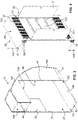
- the 1 shows a schematic perspective view of an on-board catering station 10, also called a monument, according to an exemplary embodiment of the invention in its parking position; where the 2 a further schematic perspective view of the in-flight catering station 10 of FIG 1 shows the opposite of 1 shown from the rear 90.
- the rear side 90 is correspondingly curved in relation to the aircraft side wall and follows the aircraft fuselage with its contour.
- the fastening elements with which the in-flight catering station 10 can be fastened to the aircraft fuselage and the floor are not shown in the figures.
- the rear lightweight component 20 is preferably a single wall, with a front edge 21 facing the aircraft aisle, an aircraft interior side edge 60 and a skirting board 22 with a floor surface 45. It could be provided optionally, but is generally provided as a bumper to protect the in-flight catering station 10 .
- the aircraft interior side edge 60 defined here near the ground essentially indicates that there is a distance between the plane of the rear side 90 of the station 10 and the pivoting axis 100 introduced later below, from which the technical compartment 46 will be defined.
- the front-side lightweight component 40 adjoins the rear side 90 at its edge pointing towards the aircraft wall during installation and also has a base strip 22 which merges into a front edge of a base surface 45 .
- the front light-weight component 40 has a cut-out which is completely occupied by the front surface 32 of the provision compartment 30 .
- the front light-weight member 40 and the front surface 32 of the provision compartment 30 are flush and form a common flush surface.
- a screen 33 for flight information and/or horizontal ribs 34 underneath here can be provided in the front surface 32, which protect the surface as bumpers or impact strips. Instead of ribs, pockets for information and other essentially flat elements can also be provided.
- the catering compartment 30 has an aisle-side front side 35 with, for example, a transparent pane 36 for a view of the interior of the catering compartment 30 and on the front edge 21 of the rear lightweight component 20, the catering compartment 30 has a locking arrangement 37 at the top and bottom.
- the locking arrangement 37 is in the in the 1 illustrated pivoted or parked position in the base surface 45 is locked.
- the catering compartment 30 is locked at the top in the horizontal intermediate floor 49 of the on-board catering station 10 .
- the other attachment point of the catering compartment 30 is diametrically opposite in the area of the opposite corner edge on the pivot axis 100, the bearings in Figures 3 and 4 referred to as pivoting device 101 and are arranged one above the other in the direction of the pivot axis 100 .
- the arrow 46 indicates a technical compartment, which is the space of the station 10, which exists in the area behind the vertical edge 47 of the front light-weight component and which results in particular from the fact that the catering compartment 30 is only one by the shape of the On-board catering station 10 can have a predetermined maximum height, which forms a web transition 48 between the upper partial surface 141 of the front-side lightweight component 40 and the lower lateral partial surface 142 .
- An overhead storage compartment 144 with a door 44 is provided behind the upper partial surface 141 above the intermediate floor 49 .
- the edge 47 opposite the catering compartment 30 lies parallel to the pivot axis 100, which runs obliquely inwards at a small distance in the catering compartment 30, advantageously at a 45 degree angle from the edge 47 and is therefore at the same distance from both adjacent side edges.
- the 1 shows a view from above into a possible aircraft interior.
- the catering compartment 30 points to the rear in relation to the direction of flight and the “rear” lightweight component 20 points “to the front” in the direction of flight. This is due to the convention chosen here of designating the fold-out plane of the catering compartment 30 as forward in relation to the on-board catering station.
- FIG 3 shows a further schematic perspective view of the shell of the in-flight catering station 10 of FIG 1 without the box-shaped catering compartment 30 and 4 shows a schematic perspective view of an embodiment of a catering compartment 30 for use in the embodiment according to FIG 1 , with doors 131 of the catering compartment 30 being opened for a look inside.
- figure 5 shows a further schematic perspective view of the on-board catering station 10 of FIG 3 with the box-shaped catering compartment 30 inserted 4 .
- 6 shows a further schematic perspective view of the on-board catering station 10 of FIG 1 , the opposite of figure 5 shown from rear 90;
- the locking opening is identified by reference number 137, which interacts with the locking arrangement 37, with which units in aircraft, such as doors, are locked in the closed position. Therefore, this locking opening 137 is arranged below in the floor / base surface 45 near the inside 23 of the rear lightweight component 20 and correspondingly from below in the intermediate floor 49.
- the associated locking device 37 is in 4 seen on the top 38 in the front right corner.
- the pivot axis 100 is shown schematically, which passes through the protruding cylinder 101 above the top 38 and below the bottom.
- the protruding cylinder 101 is part of the pivoting device and fits into a corresponding cylinder socket 102 provided in the base surface 45 .
- a reverse solution with attached bolts under the intermediate floor 49 and on the base surface 45 is also conceivable if corresponding cylinder receptacles are provided in the body of the top and bottom of the catering compartment 30 .
- Display shelves 132 arranged at an angle are provided behind the doors 131 of the catering compartment 30 .
- Cross roller shutter doors 133 can be provided above and below the cabinet. However, it is more common to provide these two spaces at the top and bottom around the cabinet with the doors 131 as further drawers with doors or to design these surfaces as decorative strips.
- FIG. 7 shows a side view of another on-board catering station 10' with another catering compartment 130 pivoted; and 8 shows a schematic perspective view of a compared to the 4 another embodiment of a catering compartment 130 for use in the embodiment according to 7 , wherein doors 131 of the catering compartment 130 are opened to look inside.
- a storage space can be provided in the cavity behind the doors 131, there can be further open display shelves 132, a hot water preparation 134 and a coffee machine with a hot plate 135.
- These elements which require an electrical power supply and possibly a water supply, are given here by way of example because the arrangement of the fully pivotable catering compartment 30 or 130 can provide such additional elements in the technical compartment 46, which can then be connected directly to supply lines that are not visible in the drawings.
- This technical compartment 46 is available in a width (relative to the fuselage) that corresponds to the space 81 for the escape slide elements.
- the arrangement of the catering compartment 30 or 130 in the use position is pivoted by 90 degrees in relation to the parking position after the locks 37/137 have been released. Because then a rotation of the catering compartment 30 or 130 by 90 degrees results in the locking arrangements 39 located in the parking position near the technical compartment 46 and the inside of the rear lightweight component 20 being provided opposite the locking arrangement openings designated with the reference number 139 and thus the monument in simple way in the use position can be safely determined.
- the distance between the pivot axis 100 and the axis of the use position lock 110 corresponds to that in 7 shown more than a third of the pivoted-out length of the rotated catering compartment 30 or 130, which in the illustrated embodiment has a depth-to-width ratio of two to five, ie 40%.
- This distance between the locking and rotation axes 110 and 100 is at least 25% and a maximum of 50% of the distance in the longitudinal direction of the cabinet compartment 30, 130 between 100 and the lock 37 in order to ensure good functionality due to the existing depth of the compartment with a secure lock connect to.
Landscapes
- Engineering & Computer Science (AREA)
- Aviation & Aerospace Engineering (AREA)
- Handcart (AREA)
Applications Claiming Priority (1)
| Application Number | Priority Date | Filing Date | Title |
|---|---|---|---|
| EP20210838 | 2020-11-30 |
Publications (2)
| Publication Number | Publication Date |
|---|---|
| EP4005923A1 true EP4005923A1 (fr) | 2022-06-01 |
| EP4005923B1 EP4005923B1 (fr) | 2023-08-30 |
Family
ID=73654632
Family Applications (1)
| Application Number | Title | Priority Date | Filing Date |
|---|---|---|---|
| EP20215644.4A Active EP4005923B1 (fr) | 2020-11-30 | 2020-12-18 | Station de ravitaillement embarquée |
Country Status (1)
| Country | Link |
|---|---|
| EP (1) | EP4005923B1 (fr) |
Citations (5)
| Publication number | Priority date | Publication date | Assignee | Title |
|---|---|---|---|---|
| EP2552963A1 (fr) | 2010-03-30 | 2013-02-06 | Pierre Fabre Médicament | Anticorps anti-cxcr4 humanisés pour le traitement de cancer |
| US20170283059A1 (en) | 2016-04-04 | 2017-10-05 | B/E Aerospace, Inc. | Aircraft Monument |
| EP3552963A1 (fr) | 2018-04-10 | 2019-10-16 | Rockwell Collins, Inc. | Monuments multimode transformables pour espaces de porte d'aéronef |
| US20190337623A1 (en) | 2018-04-10 | 2019-11-07 | Rockwell Collins, Inc. | Self-Deploying Counter for Multimode Transformable Monuments |
| EP3736214A1 (fr) | 2019-05-10 | 2020-11-11 | Be Aerospace, Inc. | Monument d'aéronef étroit doté d'un poste de travail déployable |
-
2020
- 2020-12-18 EP EP20215644.4A patent/EP4005923B1/fr active Active
Patent Citations (5)
| Publication number | Priority date | Publication date | Assignee | Title |
|---|---|---|---|---|
| EP2552963A1 (fr) | 2010-03-30 | 2013-02-06 | Pierre Fabre Médicament | Anticorps anti-cxcr4 humanisés pour le traitement de cancer |
| US20170283059A1 (en) | 2016-04-04 | 2017-10-05 | B/E Aerospace, Inc. | Aircraft Monument |
| EP3552963A1 (fr) | 2018-04-10 | 2019-10-16 | Rockwell Collins, Inc. | Monuments multimode transformables pour espaces de porte d'aéronef |
| US20190337623A1 (en) | 2018-04-10 | 2019-11-07 | Rockwell Collins, Inc. | Self-Deploying Counter for Multimode Transformable Monuments |
| EP3736214A1 (fr) | 2019-05-10 | 2020-11-11 | Be Aerospace, Inc. | Monument d'aéronef étroit doté d'un poste de travail déployable |
Also Published As
| Publication number | Publication date |
|---|---|
| EP4005923B1 (fr) | 2023-08-30 |
Similar Documents
| Publication | Publication Date | Title |
|---|---|---|
| EP2536630B1 (fr) | Installation de toilettes pour moyen de transport | |
| DE60203014T2 (de) | Fahrzeugkabine zur unterbringung von passagieren | |
| DE69725542T2 (de) | Fluggastsitz, drehbar und veränderbar in ein Bett | |
| EP2423107B1 (fr) | Agencement de réception de passagers dans un moyen de transport | |
| DE69613045T2 (de) | Verlängerung für Gepäckablage | |
| DE69734433T2 (de) | Toilette mit verstaubarem Modul zur Verwendung an Bord von Fahrzeugen, z.B. Flugzeugen | |
| EP2456650B1 (fr) | Tramway doté d'un siège rabattable supplémentaire pour la cabine de conduite | |
| EP0035955A2 (fr) | Avion avec récipient de transport ou conteneur | |
| DE102011016031A1 (de) | Kabinensegment, Kabine und Fahrzeug mit einer Kabine | |
| DE102016105503B4 (de) | System zum Aufnehmen von Fracht oder Passagieren in einem Fahrzeug sowie ein Fahrzeug mit einem derartigen System | |
| DE102012005980A1 (de) | Adapter zum Befestigen eines Sitzes in einer Kabine eines Fahrzeugs, Sitz für eine Kabine eines Fahrzeugs, Fahrzeug mit einer Kabine und einem Sitz | |
| DE102016207607A1 (de) | Erweiterbares Flugzeugmonument und Flugzeugbereich mit einem erweiterbaren Flugzeugmonument | |
| DE102009008355A1 (de) | Arbeitsbereich in einem Luftfahrzeug | |
| DE102015116804A1 (de) | Raumeffizientes Kabinensegment für ein Fahrzeug sowie eine Passagierkabine mit einer Mehrzahl von Sitzen und einem solchen Kabinensegment | |
| EP2318275B1 (fr) | Couchette | |
| DE102013021108A1 (de) | Flugzeuggepäcksystem mit einem Gepäckfach und einem Zusatzgepäckfach | |
| DE102017111913A1 (de) | Monumentenanordnung in einer Kabine eines Fahrzeugs, eine Kabine eines Fahrzeugs sowie ein Fahrzeug mit einer derartigen Kabine | |
| DE102015116585A1 (de) | Kompakte Funktionsanordnung in einer Kabine eines Fahrzeugs und Fahrzeug mit einer solchen Funktionsanordnung | |
| DE102011116523B4 (de) | Flugzeugbereich mit einem Stauschrank für Notfallausrüstungsgegenstände | |
| DE102015116798B4 (de) | Raumoptimierte Kabinenanordnung für ein Fahrzeug sowie eine Passagierkabine mit einer Mehrzahl von Sitzen und einer solchen Kabinenanordnung | |
| EP4005923B1 (fr) | Station de ravitaillement embarquée | |
| DE102016103825A1 (de) | Anordnung in einer Fahrzeugkabine mit einem Kabinenmonument mit zwei Zugangsöffnungen an zwei eine Schnittfläche ausbildenden Gängen | |
| DE102019123321A1 (de) | Sitzanordnung für eine Kabine eines Transportmittels | |
| DE102016106279B4 (de) | Anordnung in einer Kabine eines Flugzeugs sowie ein Flugzeug mit mindestens einer derartigen Anordnung | |
| DE102018117024B3 (de) | Flugzeugbodenelement, Flugzeugabschnitt und Flugzeug mit einem Flugzeugbodenelement |
Legal Events
| Date | Code | Title | Description |
|---|---|---|---|
| PUAI | Public reference made under article 153(3) epc to a published international application that has entered the european phase |
Free format text: ORIGINAL CODE: 0009012 |
|
| STAA | Information on the status of an ep patent application or granted ep patent |
Free format text: STATUS: THE APPLICATION HAS BEEN PUBLISHED |
|
| AK | Designated contracting states |
Kind code of ref document: A1 Designated state(s): AL AT BE BG CH CY CZ DE DK EE ES FI FR GB GR HR HU IE IS IT LI LT LU LV MC MK MT NL NO PL PT RO RS SE SI SK SM TR |
|
| STAA | Information on the status of an ep patent application or granted ep patent |
Free format text: STATUS: REQUEST FOR EXAMINATION WAS MADE |
|
| 17P | Request for examination filed |
Effective date: 20221007 |
|
| RBV | Designated contracting states (corrected) |
Designated state(s): AL AT BE BG CH CY CZ DE DK EE ES FI FR GB GR HR HU IE IS IT LI LT LU LV MC MK MT NL NO PL PT RO RS SE SI SK SM TR |
|
| GRAP | Despatch of communication of intention to grant a patent |
Free format text: ORIGINAL CODE: EPIDOSNIGR1 |
|
| STAA | Information on the status of an ep patent application or granted ep patent |
Free format text: STATUS: GRANT OF PATENT IS INTENDED |
|
| INTG | Intention to grant announced |
Effective date: 20230327 |
|
| GRAS | Grant fee paid |
Free format text: ORIGINAL CODE: EPIDOSNIGR3 |
|
| GRAA | (expected) grant |
Free format text: ORIGINAL CODE: 0009210 |
|
| STAA | Information on the status of an ep patent application or granted ep patent |
Free format text: STATUS: THE PATENT HAS BEEN GRANTED |
|
| AK | Designated contracting states |
Kind code of ref document: B1 Designated state(s): AL AT BE BG CH CY CZ DE DK EE ES FI FR GB GR HR HU IE IS IT LI LT LU LV MC MK MT NL NO PL PT RO RS SE SI SK SM TR |
|
| REG | Reference to a national code |
Ref country code: GB Ref legal event code: FG4D Free format text: NOT ENGLISH |
|
| REG | Reference to a national code |
Ref country code: CH Ref legal event code: EP |
|
| REG | Reference to a national code |
Ref country code: DE Ref legal event code: R096 Ref document number: 502020004976 Country of ref document: DE |
|
| REG | Reference to a national code |
Ref country code: IE Ref legal event code: FG4D Free format text: LANGUAGE OF EP DOCUMENT: GERMAN |
|
| REG | Reference to a national code |
Ref country code: LT Ref legal event code: MG9D |
|
| REG | Reference to a national code |
Ref country code: NL Ref legal event code: MP Effective date: 20230830 |
|
| PG25 | Lapsed in a contracting state [announced via postgrant information from national office to epo] |
Ref country code: GR Free format text: LAPSE BECAUSE OF FAILURE TO SUBMIT A TRANSLATION OF THE DESCRIPTION OR TO PAY THE FEE WITHIN THE PRESCRIBED TIME-LIMIT Effective date: 20231201 |
|
| PG25 | Lapsed in a contracting state [announced via postgrant information from national office to epo] |
Ref country code: IS Free format text: LAPSE BECAUSE OF FAILURE TO SUBMIT A TRANSLATION OF THE DESCRIPTION OR TO PAY THE FEE WITHIN THE PRESCRIBED TIME-LIMIT Effective date: 20231230 |
|
| PG25 | Lapsed in a contracting state [announced via postgrant information from national office to epo] |
Ref country code: SE Free format text: LAPSE BECAUSE OF FAILURE TO SUBMIT A TRANSLATION OF THE DESCRIPTION OR TO PAY THE FEE WITHIN THE PRESCRIBED TIME-LIMIT Effective date: 20230830 Ref country code: RS Free format text: LAPSE BECAUSE OF FAILURE TO SUBMIT A TRANSLATION OF THE DESCRIPTION OR TO PAY THE FEE WITHIN THE PRESCRIBED TIME-LIMIT Effective date: 20230830 Ref country code: NO Free format text: LAPSE BECAUSE OF FAILURE TO SUBMIT A TRANSLATION OF THE DESCRIPTION OR TO PAY THE FEE WITHIN THE PRESCRIBED TIME-LIMIT Effective date: 20231130 Ref country code: LV Free format text: LAPSE BECAUSE OF FAILURE TO SUBMIT A TRANSLATION OF THE DESCRIPTION OR TO PAY THE FEE WITHIN THE PRESCRIBED TIME-LIMIT Effective date: 20230830 Ref country code: LT Free format text: LAPSE BECAUSE OF FAILURE TO SUBMIT A TRANSLATION OF THE DESCRIPTION OR TO PAY THE FEE WITHIN THE PRESCRIBED TIME-LIMIT Effective date: 20230830 Ref country code: IS Free format text: LAPSE BECAUSE OF FAILURE TO SUBMIT A TRANSLATION OF THE DESCRIPTION OR TO PAY THE FEE WITHIN THE PRESCRIBED TIME-LIMIT Effective date: 20231230 Ref country code: HR Free format text: LAPSE BECAUSE OF FAILURE TO SUBMIT A TRANSLATION OF THE DESCRIPTION OR TO PAY THE FEE WITHIN THE PRESCRIBED TIME-LIMIT Effective date: 20230830 Ref country code: GR Free format text: LAPSE BECAUSE OF FAILURE TO SUBMIT A TRANSLATION OF THE DESCRIPTION OR TO PAY THE FEE WITHIN THE PRESCRIBED TIME-LIMIT Effective date: 20231201 Ref country code: FI Free format text: LAPSE BECAUSE OF FAILURE TO SUBMIT A TRANSLATION OF THE DESCRIPTION OR TO PAY THE FEE WITHIN THE PRESCRIBED TIME-LIMIT Effective date: 20230830 |
|
| PG25 | Lapsed in a contracting state [announced via postgrant information from national office to epo] |
Ref country code: PL Free format text: LAPSE BECAUSE OF FAILURE TO SUBMIT A TRANSLATION OF THE DESCRIPTION OR TO PAY THE FEE WITHIN THE PRESCRIBED TIME-LIMIT Effective date: 20230830 Ref country code: NL Free format text: LAPSE BECAUSE OF FAILURE TO SUBMIT A TRANSLATION OF THE DESCRIPTION OR TO PAY THE FEE WITHIN THE PRESCRIBED TIME-LIMIT Effective date: 20230830 |
|
| PG25 | Lapsed in a contracting state [announced via postgrant information from national office to epo] |
Ref country code: ES Free format text: LAPSE BECAUSE OF FAILURE TO SUBMIT A TRANSLATION OF THE DESCRIPTION OR TO PAY THE FEE WITHIN THE PRESCRIBED TIME-LIMIT Effective date: 20230830 |
|
| PG25 | Lapsed in a contracting state [announced via postgrant information from national office to epo] |
Ref country code: SM Free format text: LAPSE BECAUSE OF FAILURE TO SUBMIT A TRANSLATION OF THE DESCRIPTION OR TO PAY THE FEE WITHIN THE PRESCRIBED TIME-LIMIT Effective date: 20230830 Ref country code: RO Free format text: LAPSE BECAUSE OF FAILURE TO SUBMIT A TRANSLATION OF THE DESCRIPTION OR TO PAY THE FEE WITHIN THE PRESCRIBED TIME-LIMIT Effective date: 20230830 Ref country code: ES Free format text: LAPSE BECAUSE OF FAILURE TO SUBMIT A TRANSLATION OF THE DESCRIPTION OR TO PAY THE FEE WITHIN THE PRESCRIBED TIME-LIMIT Effective date: 20230830 Ref country code: EE Free format text: LAPSE BECAUSE OF FAILURE TO SUBMIT A TRANSLATION OF THE DESCRIPTION OR TO PAY THE FEE WITHIN THE PRESCRIBED TIME-LIMIT Effective date: 20230830 Ref country code: DK Free format text: LAPSE BECAUSE OF FAILURE TO SUBMIT A TRANSLATION OF THE DESCRIPTION OR TO PAY THE FEE WITHIN THE PRESCRIBED TIME-LIMIT Effective date: 20230830 Ref country code: CZ Free format text: LAPSE BECAUSE OF FAILURE TO SUBMIT A TRANSLATION OF THE DESCRIPTION OR TO PAY THE FEE WITHIN THE PRESCRIBED TIME-LIMIT Effective date: 20230830 Ref country code: SK Free format text: LAPSE BECAUSE OF FAILURE TO SUBMIT A TRANSLATION OF THE DESCRIPTION OR TO PAY THE FEE WITHIN THE PRESCRIBED TIME-LIMIT Effective date: 20230830 Ref country code: PT Free format text: LAPSE BECAUSE OF FAILURE TO SUBMIT A TRANSLATION OF THE DESCRIPTION OR TO PAY THE FEE WITHIN THE PRESCRIBED TIME-LIMIT Effective date: 20240102 |
|
| PG25 | Lapsed in a contracting state [announced via postgrant information from national office to epo] |
Ref country code: IT Free format text: LAPSE BECAUSE OF FAILURE TO SUBMIT A TRANSLATION OF THE DESCRIPTION OR TO PAY THE FEE WITHIN THE PRESCRIBED TIME-LIMIT Effective date: 20230830 |
|
| REG | Reference to a national code |
Ref country code: DE Ref legal event code: R097 Ref document number: 502020004976 Country of ref document: DE |
|
| PLBE | No opposition filed within time limit |
Free format text: ORIGINAL CODE: 0009261 |
|
| STAA | Information on the status of an ep patent application or granted ep patent |
Free format text: STATUS: NO OPPOSITION FILED WITHIN TIME LIMIT |
|
| PG25 | Lapsed in a contracting state [announced via postgrant information from national office to epo] |
Ref country code: SI Free format text: LAPSE BECAUSE OF FAILURE TO SUBMIT A TRANSLATION OF THE DESCRIPTION OR TO PAY THE FEE WITHIN THE PRESCRIBED TIME-LIMIT Effective date: 20230830 |
|
| 26N | No opposition filed |
Effective date: 20240603 |
|
| PG25 | Lapsed in a contracting state [announced via postgrant information from national office to epo] |
Ref country code: LU Free format text: LAPSE BECAUSE OF NON-PAYMENT OF DUE FEES Effective date: 20231218 |
|
| PG25 | Lapsed in a contracting state [announced via postgrant information from national office to epo] |
Ref country code: MC Free format text: LAPSE BECAUSE OF FAILURE TO SUBMIT A TRANSLATION OF THE DESCRIPTION OR TO PAY THE FEE WITHIN THE PRESCRIBED TIME-LIMIT Effective date: 20230830 |
|
| REG | Reference to a national code |
Ref country code: BE Ref legal event code: MM Effective date: 20231231 |
|
| PG25 | Lapsed in a contracting state [announced via postgrant information from national office to epo] |
Ref country code: MC Free format text: LAPSE BECAUSE OF FAILURE TO SUBMIT A TRANSLATION OF THE DESCRIPTION OR TO PAY THE FEE WITHIN THE PRESCRIBED TIME-LIMIT Effective date: 20230830 Ref country code: LU Free format text: LAPSE BECAUSE OF NON-PAYMENT OF DUE FEES Effective date: 20231218 |
|
| REG | Reference to a national code |
Ref country code: IE Ref legal event code: MM4A |
|
| PG25 | Lapsed in a contracting state [announced via postgrant information from national office to epo] |
Ref country code: IE Free format text: LAPSE BECAUSE OF NON-PAYMENT OF DUE FEES Effective date: 20231218 |
|
| PG25 | Lapsed in a contracting state [announced via postgrant information from national office to epo] |
Ref country code: BE Free format text: LAPSE BECAUSE OF NON-PAYMENT OF DUE FEES Effective date: 20231231 |
|
| PG25 | Lapsed in a contracting state [announced via postgrant information from national office to epo] |
Ref country code: IE Free format text: LAPSE BECAUSE OF NON-PAYMENT OF DUE FEES Effective date: 20231218 Ref country code: BE Free format text: LAPSE BECAUSE OF NON-PAYMENT OF DUE FEES Effective date: 20231231 |
|
| PG25 | Lapsed in a contracting state [announced via postgrant information from national office to epo] |
Ref country code: BG Free format text: LAPSE BECAUSE OF FAILURE TO SUBMIT A TRANSLATION OF THE DESCRIPTION OR TO PAY THE FEE WITHIN THE PRESCRIBED TIME-LIMIT Effective date: 20230830 |
|
| PG25 | Lapsed in a contracting state [announced via postgrant information from national office to epo] |
Ref country code: BG Free format text: LAPSE BECAUSE OF FAILURE TO SUBMIT A TRANSLATION OF THE DESCRIPTION OR TO PAY THE FEE WITHIN THE PRESCRIBED TIME-LIMIT Effective date: 20230830 |
|
| PG25 | Lapsed in a contracting state [announced via postgrant information from national office to epo] |
Ref country code: CY Free format text: LAPSE BECAUSE OF FAILURE TO SUBMIT A TRANSLATION OF THE DESCRIPTION OR TO PAY THE FEE WITHIN THE PRESCRIBED TIME-LIMIT; INVALID AB INITIO Effective date: 20201218 |
|
| PG25 | Lapsed in a contracting state [announced via postgrant information from national office to epo] |
Ref country code: HU Free format text: LAPSE BECAUSE OF FAILURE TO SUBMIT A TRANSLATION OF THE DESCRIPTION OR TO PAY THE FEE WITHIN THE PRESCRIBED TIME-LIMIT; INVALID AB INITIO Effective date: 20201218 |
|
| PG25 | Lapsed in a contracting state [announced via postgrant information from national office to epo] |
Ref country code: TR Free format text: LAPSE BECAUSE OF FAILURE TO SUBMIT A TRANSLATION OF THE DESCRIPTION OR TO PAY THE FEE WITHIN THE PRESCRIBED TIME-LIMIT Effective date: 20230830 |
|
| REG | Reference to a national code |
Ref country code: CH Ref legal event code: U11 Free format text: ST27 STATUS EVENT CODE: U-0-0-U10-U11 (AS PROVIDED BY THE NATIONAL OFFICE) Effective date: 20260101 |
|
| PGFP | Annual fee paid to national office [announced via postgrant information from national office to epo] |
Ref country code: DE Payment date: 20251211 Year of fee payment: 6 |
|
| PGFP | Annual fee paid to national office [announced via postgrant information from national office to epo] |
Ref country code: GB Payment date: 20251219 Year of fee payment: 6 |
|
| PGFP | Annual fee paid to national office [announced via postgrant information from national office to epo] |
Ref country code: AT Payment date: 20260113 Year of fee payment: 5 |
|
| PGFP | Annual fee paid to national office [announced via postgrant information from national office to epo] |
Ref country code: FR Payment date: 20251229 Year of fee payment: 6 |
|
| PGFP | Annual fee paid to national office [announced via postgrant information from national office to epo] |
Ref country code: CH Payment date: 20260101 Year of fee payment: 6 |