EP4005931B1 - Écrou d'ancrage pour un système de capuchon de protection eme - Google Patents
Écrou d'ancrage pour un système de capuchon de protection eme Download PDFInfo
- Publication number
- EP4005931B1 EP4005931B1 EP22152477.0A EP22152477A EP4005931B1 EP 4005931 B1 EP4005931 B1 EP 4005931B1 EP 22152477 A EP22152477 A EP 22152477A EP 4005931 B1 EP4005931 B1 EP 4005931B1
- Authority
- EP
- European Patent Office
- Prior art keywords
- cap
- cap member
- nut member
- opening
- sidewall
- Prior art date
- Legal status (The legal status is an assumption and is not a legal conclusion. Google has not performed a legal analysis and makes no representation as to the accuracy of the status listed.)
- Active
Links
Images


Classifications
-
- F—MECHANICAL ENGINEERING; LIGHTING; HEATING; WEAPONS; BLASTING
- F16—ENGINEERING ELEMENTS AND UNITS; GENERAL MEASURES FOR PRODUCING AND MAINTAINING EFFECTIVE FUNCTIONING OF MACHINES OR INSTALLATIONS; THERMAL INSULATION IN GENERAL
- F16B—DEVICES FOR FASTENING OR SECURING CONSTRUCTIONAL ELEMENTS OR MACHINE PARTS TOGETHER, e.g. NAILS, BOLTS, CIRCLIPS, CLAMPS, CLIPS OR WEDGES; JOINTS OR JOINTING
- F16B37/00—Nuts or like thread-engaging members
- F16B37/14—Cap nuts; Nut caps or bolt caps
-
- F—MECHANICAL ENGINEERING; LIGHTING; HEATING; WEAPONS; BLASTING
- F16—ENGINEERING ELEMENTS AND UNITS; GENERAL MEASURES FOR PRODUCING AND MAINTAINING EFFECTIVE FUNCTIONING OF MACHINES OR INSTALLATIONS; THERMAL INSULATION IN GENERAL
- F16B—DEVICES FOR FASTENING OR SECURING CONSTRUCTIONAL ELEMENTS OR MACHINE PARTS TOGETHER, e.g. NAILS, BOLTS, CIRCLIPS, CLAMPS, CLIPS OR WEDGES; JOINTS OR JOINTING
- F16B33/00—Features common to bolt and nut
- F16B33/004—Sealing; Insulation
-
- B—PERFORMING OPERATIONS; TRANSPORTING
- B64—AIRCRAFT; AVIATION; COSMONAUTICS
- B64D—EQUIPMENT FOR FITTING IN OR TO AIRCRAFT; FLIGHT SUITS; PARACHUTES; ARRANGEMENT OR MOUNTING OF POWER PLANTS OR PROPULSION TRANSMISSIONS IN AIRCRAFT
- B64D45/00—Aircraft indicators or protectors not otherwise provided for
- B64D45/02—Lightning protectors; Static dischargers
-
- F—MECHANICAL ENGINEERING; LIGHTING; HEATING; WEAPONS; BLASTING
- F16—ENGINEERING ELEMENTS AND UNITS; GENERAL MEASURES FOR PRODUCING AND MAINTAINING EFFECTIVE FUNCTIONING OF MACHINES OR INSTALLATIONS; THERMAL INSULATION IN GENERAL
- F16B—DEVICES FOR FASTENING OR SECURING CONSTRUCTIONAL ELEMENTS OR MACHINE PARTS TOGETHER, e.g. NAILS, BOLTS, CIRCLIPS, CLAMPS, CLIPS OR WEDGES; JOINTS OR JOINTING
- F16B35/00—Screw-bolts; Stay-bolts; Screw-threaded studs; Screws; Set screws
- F16B35/04—Screw-bolts; Stay-bolts; Screw-threaded studs; Screws; Set screws with specially-shaped head or shaft in order to fix the bolt on or in an object
- F16B35/06—Specially-shaped heads
-
- F—MECHANICAL ENGINEERING; LIGHTING; HEATING; WEAPONS; BLASTING
- F16—ENGINEERING ELEMENTS AND UNITS; GENERAL MEASURES FOR PRODUCING AND MAINTAINING EFFECTIVE FUNCTIONING OF MACHINES OR INSTALLATIONS; THERMAL INSULATION IN GENERAL
- F16B—DEVICES FOR FASTENING OR SECURING CONSTRUCTIONAL ELEMENTS OR MACHINE PARTS TOGETHER, e.g. NAILS, BOLTS, CIRCLIPS, CLAMPS, CLIPS OR WEDGES; JOINTS OR JOINTING
- F16B37/00—Nuts or like thread-engaging members
- F16B37/12—Nuts or like thread-engaging members with thread-engaging surfaces formed by inserted coil-springs, discs, or the like; Independent pieces of wound wire used as nuts; Threaded inserts for holes
- F16B37/122—Threaded inserts, e.g. "rampa bolts"
- F16B37/125—Threaded inserts, e.g. "rampa bolts" the external surface of the insert being threaded
-
- H—ELECTRICITY
- H01—ELECTRIC ELEMENTS
- H01B—CABLES; CONDUCTORS; INSULATORS; SELECTION OF MATERIALS FOR THEIR CONDUCTIVE, INSULATING OR DIELECTRIC PROPERTIES
- H01B17/00—Insulators or insulating bodies characterised by their form
- H01B17/56—Insulating bodies
Definitions
- This disclosure relates to an electrical insulation cap assembly for insulating metallic fasteners from transmitting current or sparks into the vicinity of the location of the metallic fastener assembly with the occurrence of electromagnetic effect ("EME”) or lightning strike event and more particularly for electrical insulating containment caps which enclose a metallic threaded fastener.
- EME electromagnetic effect
- Electrically insulated sealant and containment caps have been used to cover an end portion of a metallic fastener assembly which includes a nut and a threaded end portion of a stud which extends beyond the nut and which may include one or more washers.
- the sealant caps electrically insulate the end portion of the metallic fastener assembly so as to electrically isolate and contain the end portion of the metallic fastener assembly from critical surroundings of the metallic fastener assembly such as within a vicinity of a fuel tank or sensitive electronic equipment within an aircraft. Electrically isolating and containing the end portion of the metallic fastener assembly prevents unwanted sparks or electrical current transmissions entering into such important surroundings upon an EME or lightning strike event.
- the insulation and containment caps are made from sealant material such as for example a thermoset plastic.
- the caps are also filled with a liquid form of sealant material. Once the cap is filled with liquid sealant, the cap is positioned over the end portion of the metallic fastener assembly enclosing the end portion of the metallic fastener assembly within the cap and a surface of a structure from which the end portion of the metallic fastener assembly extends. At times sealant is expelled from the cap being over filled with sealant. This expelling of sealant can also occur by way of a sufficient amount of sealant being present such that expelling of some sealant from the cap can occur which indicates an adequate amount of sealant has been used. The expelled sealant in either occurrence must then be smoothed out about the cap to ensure proper sealing of the cap and for aesthetics. This smoothing out process is tedious and time consuming.
- the cap also requires being held in place for a time period so as to maintain the cap's position to prevent an occurrence of the cap experiencing slumping or lifting off of the surface of a structure from which the end portion of the metallic fastener assembly extends during the curing of the sealant.
- the cap-to-structure joints are subject to high quality standards and often require rework.
- EP 2860411 A1 discloses, according to its abstract, "A cap (250) for use in covering a portion (212) of a fastener (210) protruding from a surface (206) is provided.
- the portion (212) includes threads.
- the cap (250) includes an interior (252), a base (258) that at least partially delimits the interior (252), a threaded receptacle (292) on the interior (252) configured to threadably engage the portion (212) of the fastener (210), and a seal (260) coupled to the base (258) to engage the surface (206)".
- a cap system for enclosing a metallic fastener assembly as defined in claim 1 of the appended claims.
- a cap system for enclosing a metallic fastener assembly extending through a structure which includes a first securement mechanism positioned about a periphery of a nut member of the metallic fastener assembly, wherein the first securement mechanism includes threads which are interrupted as the threads extend about the periphery of the nut member.
- the cap system further includes a cap member which includes a sidewall having an inner surface which defines a cavity dimensioned to receive the nut member and defines a second securement mechanism complementary configured to engage the first securement mechanism positioned about the periphery of the nut member.
- the cap member further includes an end of the sidewall of the cap member defines an opening which provides the nut member to have access to the cavity.
- a cap system for enclosing a metallic fastener assembly extending through a structure which includes a first securement mechanism positioned about a periphery of a nut member of the metallic fastener assembly, wherein the first securement mechanism includes continuous threads which extend about the periphery of the nut member.
- the cap system further includes a cap member which includes a sidewall having an inner surface which defines a cavity dimensioned to receive the nut member and defines a second securement mechanism complementary configured to engage the first securement mechanism positioned about the periphery of the nut member.
- the cap member further includes an end of the sidewall of the cap member defines an opening which provides the nut member to have access to the cavity.
- a cap system for enclosing a metallic fastener assembly extending through a structure which includes a first securement mechanism positioned about a periphery of a nut member of the metallic fastener assembly, wherein the first securement mechanism includes the first securement mechanism includes a plurality of grooves positioned spaced apart about the periphery of the nut member.
- the cap system further includes a cap member which includes a sidewall having an inner surface which defines a cavity dimensioned to receive the nut member and defines a second securement mechanism complementary configured to engage the first securement mechanism positioned about the periphery of the nut member.
- the cap member further includes an end of the sidewall of the cap member defines an opening which provides the nut member to have access to the cavity.
- a cap system for enclosing a metallic fastener assembly extending through a structure which includes a first securement mechanism positioned about a periphery of a nut member of the metallic fastener assembly, wherein the first securement mechanism comprises a plurality of continuous grooves which extend about the periphery of the nut member.
- the cap system further includes a cap member which includes a sidewall having an inner surface which defines a cavity dimensioned to receive the nut member and defines a second securement mechanism complementary configured to engage the first securement mechanism complementary configured to engage the first securement mechanism positioned about the periphery of the nut member.
- the cap member further includes an end of the sidewall of the cap member defines an opening which provides the nut member to have access to the cavity.
- a cap system described herein will be employed to enclose an end portion of a metallic fastener assembly which is secured to a structure, in this example, a structure positioned within an aircraft.
- the cap system has a cap member.
- the cap member is to be positioned over and enclose the end portion of the metallic fastener assembly which extends from the structure and secures to the metallic fastener assembly. With an end of the cap member positioned abutting a surface of the structure, the end portion of the metallic fastener assembly is enclosed within the confines of the cap member and a surface of the structure. With positioning the cap member to enclose the end portion of the metallic fastener assembly the cap member secures to the metallic fastener assembly.
- the cap is constructed of a nonconductive material such as a polymer, thermoset or of other nonconductive material and a nonconductive sealant material may be additionally used in association with the cap member to further electrically isolate the end portion of the metallic fastener assembly from the surrounding vicinity of the metallic fastener assembly positioned outside of the cap member.
- a nonconductive material such as a polymer, thermoset or of other nonconductive material
- a nonconductive sealant material may be additionally used in association with the cap member to further electrically isolate the end portion of the metallic fastener assembly from the surrounding vicinity of the metallic fastener assembly positioned outside of the cap member.
- Surrounding vicinities within an aircraft which would need electrical transmission isolation from a metallic fastener assembly include areas such as a fuel tank, areas which contain sensitive electronic equipment or areas which could otherwise be adversely affected by a transmission from an EME or lightning strike event such as experienced by an aircraft.
- a metallic fastener assembly in this example, could include a threaded stud which includes at one end a nut or could include a threaded bolt which at one end includes a head.
- the threaded stud is extended through the structure(s) and a nut is positioned onto the threaded stud on one side of the structure(s) to which the metallic fastener assembly is to be secured and a nut member with threads compatible to the threads of the threaded stud is engaged to the threaded stud on an opposing second side of the structure(s), the side in which the cap system to be described herein will be positioned.
- Washer(s) may be positioned between the nut member and the structure(s).
- the threaded bolt is extended through the structure(s) with the head of the threaded bolt positioned on one side of a structure(s) to which the metallic fastener assembly is to be secured and a nut member with threads compatible to the threads of the threaded bolt is engaged onto the bolt on an opposing second side of the structure(s), the side in which the cap system to be described herein will be positioned. Washer(s) may be positioned between the nut member and the structure(s).
- a compressive force is applied to the structure(s) positioned between the nut (not shown) and the nut member with respect to the threaded stud or is applied to the structure(s) positioned between the head (not shown) and the nut member with respect to the threaded bolt.
- the compressive force applied with the nut member on one of a threaded stud or threaded bolt of the metallic fastener assembly the metallic fastener assembly is in a secured position with respect to the structure.
- the cap member With the metallic fastener assembly in a secured position with respect to the structure and with a cap member of the cap system enclosing the threaded stud or the threaded bolt which extends from the structure along with the nut member and in addition any washer(s) which may be used in association with the nut member, the cap member at the same time will secure to the metallic fastener assembly and the cap member will be positioned against the structure.
- metallic fastener assembly 11 in this example, an end portion 10 of metallic fastener assembly 11 is shown projecting from surface 12 of structure 14.
- Structure 14 is shown schematically wherein structure 14 may include one or more components to which metallic fastener assembly 11 is secured.
- Metallic fastener assembly 11 in this example includes threaded stud or bolt 16 which has a nut (not shown) or head (not shown) positioned beneath structure 14. Threaded stud or threaded bolt 16 has threads 18, and in this example, metallic fastener assembly 11 includes washer 20 which is positioned surrounding threaded stud or threaded bolt16 and abuts surface 12 of structure 14.
- Metallic fastener assembly 11 further includes nut member 22 which has threads 24 positioned within nut member 22 which are compatible to engage with threads 18 of threaded stud or threaded bolt 16 wherein threaded stud or threaded bolt 16 extends through structure 14. Threads 24 of nut member 22 can engage threads 18 of threaded stud or threaded bolt 16 and be tightened down resulting in exerting a compressive force with respect to structure 14 with structure 14 positioned between nut member 22 and nut (not shown) or head (not shown) of threaded stud or threaded bolt 16, respectively, of metallic fastener assembly 11 obtaining a secured position with respect to structure 14.
- washer 20 is positioned between nut member 22 and structure 14.
- cap member 28A first example of cap system 26A is shown having cap member 28A.
- cap member 28A will be constructed of a nonconductive material such as one of a polymer, thermoset or other nonconductive materials.
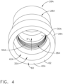
- Cap member 28A has sidewall 29A having inner surface 30A, as seen in FIGS. 2-4 , which defines cavity 32A which is dimensioned to receive nut member 22.
- First securement mechanism 34A is positioned about periphery 36A of nut member 22.
- Inner surface 30A of cap member 28A defines second securement mechanism 38A, as seen in FIG. 4 , which is complementary configured to engage first securement mechanism 34A positioned about periphery 36A of nut member 22.
- End 40A of sidewall 29A of cap member 28A defines opening 42A which provides nut member 22 to have access into cavity 32A.
- first securement mechanism 34A includes threads 44A which are interrupted or non-continuous as threads 44A extend about periphery 36A of nut member 22. Threads 44A which are interrupted are defined by a plurality of ridge members 46A positioned on nut member 22. Ridge members 46A extend in radial direction 48A away from nut member 22. Adjacent ridge members 46A of the plurality of ridge members 46A are spaced apart about nut member 22 wherein each ridge member 46A is equally spaced apart from adjacent ridge members 46A.
- This configuration of equally spaced apart ridge members 46A permit the installer to use a conventional socket wrench tool to engage nut member 22 and tighten nut member 22 onto threaded stud or threaded bolt 16 relative to structure 14 without imparting damage to threads 44A positioned on ridge members 46A.
- Second securement mechanism 38A includes threads 50A defined by inner surface 30A of sidewall 29A of cap member 28A, as seen in FIG. 4 .
- Threads 50A extend about inner surface 30A of cap member 28A and extend in a direction D away from end 40A of sidewall 29A of cap member 28A.
- end 40A of cap member 28A is positioned against structure 14 enclosing and securing to end portion 10 of metallic fastener assembly 11.
- Threads 50A With threads 50A extending in direction D, threads 50A extend toward higher elevations with respect to surface 12 with end 40A abutting surface 12as shown in FIG. 3 . Threads 50A can accommodate and engage threads 44A of nut member 22 as threads 44A may differ in elevation position relative to surface 12 as will be shown and discussed with respect to FIG. 3 , thereby ensuring securement of cap member 28A to end portion 10 of metallic fastener assembly 11 and end 40A abutting surface 12 enclosing end portion 10.
- first example 52A of end portion 10 of metallic fastener assembly 11 extending in this example above surface 12 of structure 14 is seen wherein first example of cap system 26A is shown enclosing and securing to end portion 10 of metallic fastener assembly 11.
- first example 52A nut member 22 is secured to threads 18 of threaded stud or threaded bolt 16 and directly abuts surface 12 (without a washer) and threads 44A of nut member 22 are engaged to threads 50A wherein threads 44A are positioned above surface 12 at an elevation profile lesser than that of threads 44A in second example 52A1.
- first example of cap system 26A encloses and secures to end portion 10 of metallic fastener assembly 11 positioned extending in this example above surface 12.
- nut member 22 is secured to threads 18 of threaded stud or threaded bolt 16 and is positioned on washer 20 which positions threads 44A, which are engaged to threads 50A of cap member 28A, above surface 12 at a higher elevation profile than that of threads 44A of first example 52A.
- Threads 50A of cap member 28A extend in direction D as seen in FIG.
- cap member 28A encloses end portion 10 of metallic fastener assembly 11 and secures to end portion 10 of metallic fastener assembly 11 regardless of the difference in elevation profile of threads 44A with respect to surface 12.
- cap member 28A With the installer having tightened nut member 22 onto threads 18 of threaded stud or threaded bolt 16 into a secured position relative to structure 14, the installer can then position first example of cap member 28A to have threads 44A of nut member 22 engage threads 50A of cap member 28A. The installer can then turn and tighten cap member 28A, with threads 44A and 50A engaged, until end 40A abuts surface 12. Cap member 28A is then secured to surface 12 and secured to metallic fastener assembly 11 enclosing end portion 10 of metallic fastener assembly 11.
- threads 44A of nut member 22 positioned at different elevation profiles above surface 12 can engage and reliably secure to threads 50A thereby securing cap member 28A to end portion 10 of metallic fastener assembly 11 and with end 40A abutting surface 12 cap member 28A securely encloses end portion 10 of metallic fastener assembly 11.
- cap member 28B In referring to FIG. 5 , second example of cap system 26B is shown having cap member 28B.
- cap member 28B will be constructed of a nonconductive material such as one of a polymer, thermoset or other nonconductive material.
- Cap member 28B has sidewall 29B having an inner surface 30B, as seen in FIGS. 6-8 , which defines cavity 32B which is dimensioned to receive nut member 22.
- First securement mechanism 34B as seen in FIG. 5 includes continuous threads 35B positioned to extend uninterrupted about nut member 22.
- Inner surface 30B, as seen in FIG. 8 defines second securement mechanism 38B which is complementary configured to engage first securement mechanism 34B positioned about periphery 36B of nut member 22.
- End 40B of sidewall 29B of cap member 28B defines opening 42B which provides nut member 22 to have access into cavity 32B.
- first securement mechanism 34B includes continuous threads 35B which extend uninterrupted about periphery 36B of nut member 22. Continuous threads 35B are positioned in a lower portion of nut member 22 so as not to interfere with spaced apart plurality of ridges configuration 47 positioned in an upper portion of nut member 22. Plurality of ridges configuration 47 is compatible with a standard socket wrench, in this example, for securing nut member 22 on threaded stud or threaded bolt 16 in a secured position with respect to structure 14 without imparting damage to continuous threads 35B.
- Second securement mechanism 38B includes threads 50B defined by inner surface 30B of sidewall 29B of cap member 28B, as seen in FIG. 8 .
- Threads 50B extend about inner surface 30B of sidewall 29B of cap member 28B and extend in a direction D away from end 40B of sidewall 29B of cap member 28B.
- end 40B is positioned against structure 14 enclosing end portion 10 of metallic fastener assembly 11.
- Threads 50B With threads 50B extending in direction D, threads 50B extend toward higher elevations above surface 12 of structure 14 with end 40B in abutting relationship with surface 12 of structure 14, as shown in FIG. 7 . Threads 50B can accommodate and engage continuous threads 35B of nut member 22 with continuous threads 35B positioned at different elevation profiles above surf ace 12 as seen in FIG. 7 .
- first example 52B of end portion 10 of metallic fastener assembly 11 extending in this example above surface 12 of structure 14 is seen wherein second example of cap system 26B is shown enclosing and securing to end portion 10 of metallic fastener assembly 11.
- nut member 22 is secured to threads 18 of threaded stud or threaded bolt 16 and directly abuts surface 12 (without a washer) and continuous threads 35B of nut member 22 are engaged to threads 50B wherein continuous threads 35B are positioned above surface 12 at an elevation profile lesser than continuous threads 35B of second example 52B1.
- second example of cap system 26B encloses and secures to end portion 10 of metallic fastener assembly 11 positioned extending above surface 12.
- nut member 22 is secured to threads 18 of threaded stud or threaded bolt 16 and is positioned on washer 20 which positions continuous threads 35B above surface 12 at a higher elevation profile than that of continuous threads 35B of first example 52B.
- Threads 50B of cap member 28B extend in direction D, as seen in FIG. 8 , permitting continuous threads 35B of nut member 22 to be engaged to threads 50B in both the first example 52B and second example 52B1 with end 40B of sidewall 29B of cap member 28B abutting surface 12 of structure 14.
- cap member 28B encloses end portion 10 of metallic fastener assembly 11 regardless of the difference in elevation profile of continuous threads 35B with respect to surface 12.
- cap member 28B is then secured to surface 12 of structure 14 enclosing end portion 10 of metallic fastener assembly 11.
- cap member 28C third example of cap system 26C is shown having cap member 28C.
- cap member 28C will be constructed of a nonconductive material such as one of a polymer, thermoset or other nonconductive material.
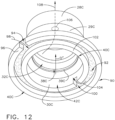
- Cap member 28C has sidewall 29C having an inner surface 30C, as seen in FIGS. 10-12 , which defines cavity 32C which is dimensioned to receive nut member 22.
- First securement 34C as seen in FIG. 9 is positioned about periphery 36C of nut member 22.
- Inner surface 30C of cap member 28C defines second securement mechanism 38C, as seen in FIG. 8 , which is complementary configured to engage first securement mechanism 34C positioned about periphery 36C of nut member 22.
- End 40C of sidewall 29C of cap member 28C defines opening 42C which provides nut member 22 to have access into cavity 32C.
- first securement mechanism 34C includes a plurality of grooves 37C positioned spaced apart about periphery 36C of nut member 22.
- Plurality of ridge members 46C which extend in a radial direction 48C away from nut member 22 define a plurality of grooves 37C.
- Adjacent ridge members 46C are spaced apart about nut member 22.
- Each of the plurality of ridge members 46C is equally spaced apart from adjacent ridge members 46C.
- a portion of plurality of grooves 37C are positioned spaced apart on each ridge member 46C aligned in a row 47C, as seen in FIG. 9 .
- Rows 47C of a portion of the plurality of grooves 37C are positioned in this example on each of ridge members 46C positioned about nut member 22. Rows 47C extend in direction D' which extends in the direction of thickness T of nut member 22. This configuration of spaced apart ridge members 46C permit the installer to use a conventional socket wrench tool to engage nut member 22 and tighten nut member 22 onto threaded stud or threaded bolt 16 relative to structure 14 without imparting damage to portions of plurality of grooves 37C positioned on ridge members 46C.
- Second securement mechanism 38C which includes at least one annular ledge 39C defined by inner surface 30C of sidewall 29C of cap member 28C. At least one annular ledge 39C is positioned about inner surface 30C of cap member 28C. At least one annular ledge 39C is positioned spaced away in a direction D" from end 40C of cap member 28C such that with nut member 22 and threaded stud or threaded bolt 16 of metallic fastener assembly 11 in a secured position with respect to structure 14 and with at least one annular ledge 39C engaging at least a portion of the plurality of grooves 37C, end 40C of cap member 28C is positioned against structure 14.
- Nut member 22 is constructed, in this example, with metallic material and is less flexible than at least one annular ledge 39C constructed of a more flexible material such as a polymer or thermoset material wherein as the installer pushes down on cap member 28C over end portion 10 of metallic fastener assembly 11 at least one annular ledge 39C will flex against nut member 22.
- at least one annular ledge 39C will flex back into plurality of grooves 37C as grooves 37C come into alignment with at least one annular ledge 39C.
- end 40C of cap member 28C abuts against surface 12 of structure 14 and at least one annular ledge 39C is in alignment with plurality of grooves 37C, cap member 28C is secured to end portion 10 of metallic fastener assembly 11and against surface 12.
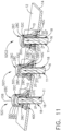
- FIG. 11 a schematic first example 52C of end portion 10 of metallic fastener assembly 11 extending above surface 12 of structure 14 is seen wherein third example of cap system 26C is shown enclosing and securing to end portion 10 of metallic fastener assembly 11.
- nut member 22 is secured to one of threaded stud or threaded bolt 16 directly abuts surface 12 (without a washer) placing grooves 37C, as seen in FIG. 9 , on each row 47C at predetermined elevations above surface 12 of structure 14.
- grooves 37a, 37b and 37c will be positioned at predetermined elevations above surface 12 with nut member 22, in this first example 52C, abutting surface 12 of structure 14.
- At least one annular ledge 39C of cap member 28C can be positioned spaced away in direction D" from end 40C, such that with end 40C abutting surface 12, at least one annular ledge 39C engages grooves 37C at an elevation above surface 12 which are positioned for example as groove 37a.
- nut member 22 is secured to one of threaded stud or threaded bolt 16 and is positioned on washer 20 positioning plurality of grooves 37C at a higher elevation profile above surface 12 than positioned in first example 52C.
- at least one annular ledge 39C of cap member 28C engages grooves 37C at an elevation above surface 12 which are positioned as groove 37b, for example as seen in FIGS. 9 and 10 , with end 40C abutting surface 12 of structure 14.
- nut member 22 is secured to one of threaded stud or threaded bolt 16 and is positioned on washer 20' and washer 20" positioning plurality of grooves 37C at a higher elevation profile above surface 12 than positioned in second example 52C1.
- at least one annular ledge 39C of cap member 28C engages grooves 37C at an elevation above surface 12 which are positioned as groove 37c, for example as seen in FIGS. 9 and 10 , with end 40C abutting surface 12 of structure 14.
- At least one annular ledge 39C can be positioned within cap member 28C spaced away from end 40C such that with nut member 22 positioned on surface 12 or on washer 20 or on washer 20' and washer 20", at least one annular ledge 39C is positioned within cap member 28C to engage grooves 37C such as 37a, 37b or 37c, as described above, with end 40C abutting surface 12 of structure 14.
- cap system 26C the installer having tightened nut member 22 on threaded stud or threaded bolt 16 into a secured position relative to structure 14, the installer can then position third example of cap member 28C over nut member 22 and push cap member 28C over nut member 22 flexing at least one annular ledge 39C of inner surface 30C of cap member 28C until cap member 28C abuts surface 12 of structure 14 and plurality of grooves 37C of nut member 22 engage at least one annular ledge 39C. Cap member 28C is then secured to end portion 10 and abuts surface 12 of structure 14 enclosing end portion 10 of metallic fastener assembly 11.
- plurality of grooves 37C of nut member 22 positioned at different predetermined elevation profiles above surface 12, such as in this example 37a, 37b and 37c, can engage and reliably secure at least one annular ledge 39C securing cap member 28C to end portion 10 of metallic fastener assembly 11 with end 40C abutting surface 12 thereby securing to and enclosing end portion 10 of metallic fastener assembly 11.
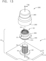
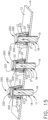
- cap member 28D In referring to FIG. 13 , fourth example of cap system 26D is shown having cap member 28D.
- cap member 28D will be constructed of a nonconductive material such as one of a polymer, thermoset or other nonconductive material.
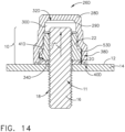
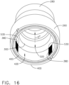
- Cap member 28D has sidewall 29D having an inner surface 30D, as seen in FIGS. 14-16 which defines cavity 32D which is dimensioned to receive nut member 22.
- First securement 34D as seen in FIG. 13 is positioned about periphery 36D of nut member 22.
- Inner surface 30D of cap member 28D defines second securement mechanism 38D, as seen in FIG. 16 , which is complementary configured to engage first securement mechanism 34D positioned about periphery 36D of nut member 22.
- End 40D of sidewall 29D of cap member 28D defines opening 42D which provides nut member 22 to have access into cavity 32D.
- first securement mechanism 34D includes a plurality of continuous grooves 41D which extend about periphery 36D of nut member 22.
- Continuous grooves 41D are positioned in a lower portion of nut member 22 so as not to interfere with plurality of ridges configuration 51 positioned in an upper portion of nut member 22.
- Plurality of ridges configuration 51 is compatible with a standard socket wrench, in this example, for securing nut member 22 on threaded stud or threaded bolt 16 in a secured position with respect to structure 14 without imparting damage to continuous grooves 41D.
- Second securement mechanism 38D which includes a plurality of teeth 53D positioned along inner surface 30D of sidewall 29D of cap member 28D.
- Plurality of teeth 53D are positioned about at least a portion of inner surface 30D of cap member 28D.
- Plurality of teeth 53D are positioned extending in a direction D′′′ along inner surface 30D of cap member 28D away from end 40D of cap member 28D such that with nut member 22 and threaded stud or threaded bolt 16 of metallic fastener assembly 11 in a secured position with respect to structure 14 and with at least a portion of plurality of teeth 53D engaging at least a portion of the plurality of continuous grooves 41D, end 40D of cap member 28D is positioned against structure 14.
- Nut member 22 is constructed, in this example, with metallic material and is less flexible than plurality of teeth 53D constructed of a more flexible material such as a polymer or thermoset material wherein as the installer pushes down on cap member 28D over end portion 10 of metallic fastener assembly 11 plurality of teeth 53D will flex against nut member 22. In this example, plurality of teeth 53D will flex back into plurality of continuous grooves 41D as continuous grooves 41D come into alignment with plurality of teeth 53D. Once end 40D of cap member 28D abuts against surface 12 of structure 14 and plurality of teeth 53D are in alignment with plurality of continuous grooves 41D, cap member 28D is secured to nut member 22 of end portion of metallic fastener assembly 11 and is positioned against surface 12.
- a more flexible material such as a polymer or thermoset material
- first example 52D of end portion 10 of metallic fastener assembly 11 extending above surface 12 of structure 14 is seen wherein fourth example of cap system 26D is shown enclosing and securing to end portion 10 of metallic fastener assembly 11.
- nut member 22 is secured to one of threaded stud or threaded bolt 16 and directly abuts surface 12 (without a washer) and continuous grooves 41D of nut member 22 are engaged by plurality of teeth 53D and are positioned above surface 12 at an elevation profile lesser than that of second example 52D1.
- second example 52D1 fourth example of cap system 26D encloses and secures to end portion 10 of metallic fastener assembly 11 positioned extending above surface 12.
- nut member 22 is secured to one of threaded stud or threaded bolt 16 and is positioned on washer 20 which positions plurality of continuous grooves 41D above surface 12 at a higher elevation profile than that of plurality of continuous grooves 41D of first example 52D.
- Plurality of teeth 53D within cap member 28D extending in direction D′′′ as seen in FIGS.
- 15 and 16 permit plurality of continuous grooves 41D of nut member 22 to be engaged in both the first example 52D and second example 52D1 with end 40D of sidewall 29D of cap member 28D abutting surface 12 of structure 14 thereby providing a secured enclosure of end portion 10 of metallic fastener assembly 11 regardless of the difference in elevation profile of plurality of continuous grooves 41D with respect to surface 12.
- third example 52D2 wherein nut member 22 is secured to one of threaded stud or threaded bolt 16 and is positioned on washer 20' and washer 20" raising the elevation profile of plurality of continuous grooves 41D in this third example 52D2 to even a higher elevation profile above surface 12 of structure 14 than second example 52C1.
- plurality of teeth 53D extending in direction D′′′ permit plurality of continuous grooves 41D of nut member 22 to be engaged by plurality of teeth 53D in third example 52D2 with end 40D abutting surface 12 providing a secured enclosure of end portion 10 of metallic fastener assembly 11.
- cap system 26D the installer having tightened nut member 22 on threaded stud or threaded bolt 16 into a secured position relative to structure 14, the installer can then position fourth example of cap member 28D over nut member 22 and push cap member 28D over nut member 22 flexing plurality of teeth 53D positioned on inner surface 30D of cap member 28C until cap member 28C abuts surface 12 of structure 14 and plurality of continuous grooves 41D of nut member 22 engage plurality of teeth 53D. Cap member 28D is then secured to nut member 22 of end portion 10 and abuts surface 12 of structure 14 enclosing end portion 10 of metallic fastener assembly 11.
- plurality of continuous grooves 41D of nut member 22 positioned at different elevation profiles above surface 12 can engage and reliably secure to plurality of teeth 53D securing cap member 28D to end portion 10 of metallic fastener assembly 11 with end 40D abutting surface 12 thereby securing cap member 28D to end portion 10 and enclosing end portion 10 of metallic fastener assembly 11.
- any of the three examples 60, 70 or 90 can be employed and for example, with respect to ends 40B and 40D, first or second examples 60 or 70 can be employed.
- end 40A, of cap member 28A forms a continuous annular flat surface 62 which will abut surface 12 of a planar configuration of structure 14 as seen in FIGS. 2-4 .
- Second example 70 of configuration of an end, is shown in FIGS. 8 and 16 as end 40B and 40D respectively. Since the second example 70 is the same configuration for FIG. 8 as is in FIG. 16 , second example 70 will be described for end 40B, of FIG. 8 , wherein sidewall 29B of cap member 28B defines groove 72 which extends about cap member 28B. First opening 74 defined by and extends through first portion 76 of sidewall 29B of cap member 28B communicates with groove 72 such that a first flow path 78 extends through first opening 74 and into groove 72 for conveyance of sealant through first opening 74 into groove72.
- Second opening 80 defined by and extends through first portion 76 of sidewall 29B of cap member 28B, is spaced apart about cap member 28B from first opening 74 wherein second opening 80 communicates with groove 72 such that second flow path 82 extends from groove 72 through second opening 80 of cap member 28B for conveyance of sealant.
- Second example 70 With respect to second example 70, once installer has secured cap member 28B to surface 12 of structure 14, the installer will inject a sealant material into first opening 74 having sealant flow in groove 72 about cap member 28B until sealant begins to leak from second opening 80. At that point the installer has a confirmation that sealant has been positioned within groove 72 providing additional assurance to the installer that end portion 10 of metallic fastener assembly 11 has been further electrically isolated within cap member 28B. Second example 70 configuration provides the installer ability to not expel excessive sealant onto surface 12 and reduces the need for tedious and time consuming smoothing out of excess sealant.
- Third example 90 of configuration of an end is shown in FIG. 12 as end 40C.
- Sidewall 29C of cap member 28C defines groove 92 which extends about cap member 28C.
- Third opening 94 defined by and extends through first portion 96 of sidewall 29C of cap member 28C such that third opening 94 communicates with groove 92.
- First flow path 98 extends through first portion 96 of sidewall 29C of cap member 28C and into groove 92 for conveyance of sealant.
- Fourth opening 100 defined by and extends through second portion 102 of sidewall 29C of cap member 28C such that fourth opening 100 communicates with groove 92 and fourth opening 100 communicates with cavity 32C of cap member 28C such that second flow path 104 extends from groove 92 through fourth opening 100 of sidewall 29C of cap member 28C and into cavity 32C.
- installer With sealant expelling from fifth opening 106, installer has a confirmation that sealant has been positioned within groove 92 and cavity 32C providing additional assurance to the installer that end portion 10 of metallic fastener assembly 11 has been further electrically isolated within cap member 28B.
- This third example configuration provides the installer the ability to not expel excessive sealant onto surface 12 and reduces the need for tedious and time consuming smoothing out of excess sealant.
Landscapes
- Engineering & Computer Science (AREA)
- General Engineering & Computer Science (AREA)
- Mechanical Engineering (AREA)
- Aviation & Aerospace Engineering (AREA)
- Connection Of Plates (AREA)
Claims (8)
- Système de capuchon (26C) pour entourer un ensemble dispositif de fixation métallique (11) s'étendant à travers une structure (14) d'un aéronef, le système de capuchon comprenant :un élément écrou (22) de l'ensemble dispositif de fixation métallique (11), l'élément écrou comprenant un premier mécanisme d'attache (34C) positionné autour d'une périphérie (36C) de l'élément écrou (22), dans lequel le premier mécanisme d'attache (34C) comprend une pluralité de rainures (37C) positionnées autour de la périphérie (36C) de l'élément écrou (22), dans lequel la pluralité de rainures (37C) sont espacées les unes des autres autour de la périphérie (36C) de l'élément écrou (22), et l'élément écrou (22) inclut en outre une pluralité d'éléments saillies (46C) qui s'étendent dans une direction radiale à l'opposé de l'élément écrou (22) et définissent la pluralité de rainures (37C), dans lequel des éléments saillies adjacents sont espacés les uns des autres autour de l'élément écrou (22) ;un élément capuchon électro-isolant (28C) comprenant une paroi latérale (29C) ayant une surface intérieure (30C) qui définit une cavité (32C) dimensionnée pour recevoir l'élément écrou (22) et définit un second mécanisme d'attache (38C) configuré de façon complémentaire pour entrer en prise avec le premier mécanisme d'attache (34C) positionné autour de la périphérie (36C) de l'élément écrou (22), etune extrémité (40C) de la paroi latérale (29C) de l'élément capuchon (28C) définit une ouverture (42C) qui laisse l'élément écrou (22) avoir accès dans la cavité (32C).
- Système de capuchon (26C) de la revendication 1, dans lequel :chacun de la pluralité d'éléments saillies (46C) est espacé de façon égale d'éléments saillies adjacents ; etune partie de la pluralité de rainures (37C) est positionnée de façon espacée sur chacun des éléments saillies alignés en une rangée.
- Système de capuchon (26C) de la revendication 2, dans lequel lesdits éléments saillies (46C) sont configurés pour permettre l'utilisation d'une clef à douille pour entrer en prise avec et resserrer l'élément écrou (22) sur un goujon ou boulon fileté (16) relativement à ladite structure (14).
- Système de capuchon (26C) de l'une quelconque des revendications 1 à 3, dans lequel : le second mécanisme d'attache (38C) comprend au moins un rebord annulaire (39C) positionné le long de la surface intérieure (30C) de l'élément capuchon (28C).
- Système de capuchon (26C) de la revendication 4, dans lequel l'au moins un rebord annulaire (39C) est positionné de façon espacée, dans une direction, de l'extrémité (40C) de l'élément capuchon (28C) de telle sorte que, avec l'élément écrou (22) et un d'un goujon fileté ou d'un boulon fileté de l'ensemble dispositif de fixation métallique (11) dans une position attachée par rapport à la structure (14) et avec l'au moins un rebord annulaire (39C) entrant en prise avec au moins une de la pluralité de rainures (37C), l'extrémité (40C) de l'élément capuchon (28C) soit positionnée contre la structure (14).
- Système de capuchon (26C) de l'une quelconque des revendications 1 à 5, dans lequel l'extrémité (40C) de la paroi latérale (29C) de l'élément capuchon (28C) définit une surface plate annulaire continue.
- Système de capuchon (26C) de l'une quelconque des revendications 1 à 5, dans lequel l'extrémité (40C) de la paroi latérale (29C) de l'élément capuchon (28C) définit :une rainure (72) qui s'étend autour de l'élément capuchon (28C),une première ouverture (74) définie par et s'étendant à travers une première partie (76) de la paroi latérale (29C) de l'élément capuchon (28C), dans lequel la première ouverture (74) communique avec la rainure (72) de telle sorte qu'un premier chemin d'écoulement (78) s'étende à travers la première ouverture (74) et dans la rainure (72) pour le transport de produit d'étanchéité, etune deuxième ouverture (80) définie par et s'étendant à travers la première partie (76) de la paroi latérale (29C) de l'élément capuchon (28C) et espacée, autour de l'élément capuchon, de la première ouverture (74), dans lequel la deuxième ouverture (80) communique avec la rainure (72) de telle sorte qu'un deuxième chemin d'écoulement (82) s'étende depuis la rainure (72) à travers le deuxième ouverture (80) de l'élément capuchon (28C) pour le transport de produit d'étanchéité.
- Système de capuchon (26C) de l'une quelconque des revendications 1 à 5, dans lequel l'extrémité (40C) de la paroi latérale (29C) de l'élément capuchon (28C) définit :une rainure (92) qui s'étend autour de l'élément capuchon (28C),une troisième ouverture (94) définie par et s'étendant à travers une première partie (96) de la paroi latérale (29C) de l'élément capuchon (28C), dans lequel la troisième ouverture (94) communique avec la rainure (92) de telle sorte qu'un premier chemin d'écoulement (8) s'étende à travers la première partie (96) de la paroi latérale (29C) de l'élément capuchon (28C) et dans la rainure (92) pour le transport de produit d'étanchéité,une quatrième ouverture (100) définie par et s'étendant à travers une seconde partie (102) de la paroi latérale (29C) de l'élément capuchon (28C), dans lequel la quatrième ouverture (100) communique avec la rainure (92) et la quatrième ouverture (100) communique avec la cavité (32C) de l'élément capuchon de telle sorte qu'un deuxième chemin d'écoulement (104) s'étende depuis la rainure (92), à travers la quatrième ouverture (100) de la paroi latérale (29C) de l'élément capuchon (28C), et dans la cavité (32C), etune cinquième ouverture (106) définie par et s'étendant à travers la paroi latérale (29C) de l'élément capuchon (28C), dans lequel la cinquième ouverture (106) fournit un troisième chemin d'écoulement (108), depuis la cavité (32C) de l'élément capuchon (28C), à travers la cinquième ouverture (106) de la paroi latérale (29C) de l'élément capuchon (28C).
Applications Claiming Priority (2)
| Application Number | Priority Date | Filing Date | Title |
|---|---|---|---|
| US15/960,835 US10962043B2 (en) | 2018-04-24 | 2018-04-24 | Anchoring nut for an EME protection cap system |
| EP19167831.7A EP3560839B1 (fr) | 2018-04-24 | 2019-04-08 | Écrou d'ancrage pour un système de capuchon de protection eme |
Related Parent Applications (2)
| Application Number | Title | Priority Date | Filing Date |
|---|---|---|---|
| EP19167831.7A Division EP3560839B1 (fr) | 2018-04-24 | 2019-04-08 | Écrou d'ancrage pour un système de capuchon de protection eme |
| EP19167831.7A Division-Into EP3560839B1 (fr) | 2018-04-24 | 2019-04-08 | Écrou d'ancrage pour un système de capuchon de protection eme |
Publications (2)
| Publication Number | Publication Date |
|---|---|
| EP4005931A1 EP4005931A1 (fr) | 2022-06-01 |
| EP4005931B1 true EP4005931B1 (fr) | 2024-06-05 |
Family
ID=66334154
Family Applications (2)
| Application Number | Title | Priority Date | Filing Date |
|---|---|---|---|
| EP19167831.7A Active EP3560839B1 (fr) | 2018-04-24 | 2019-04-08 | Écrou d'ancrage pour un système de capuchon de protection eme |
| EP22152477.0A Active EP4005931B1 (fr) | 2018-04-24 | 2019-04-08 | Écrou d'ancrage pour un système de capuchon de protection eme |
Family Applications Before (1)
| Application Number | Title | Priority Date | Filing Date |
|---|---|---|---|
| EP19167831.7A Active EP3560839B1 (fr) | 2018-04-24 | 2019-04-08 | Écrou d'ancrage pour un système de capuchon de protection eme |
Country Status (3)
| Country | Link |
|---|---|
| US (2) | US10962043B2 (fr) |
| EP (2) | EP3560839B1 (fr) |
| CN (1) | CN110397655B (fr) |
Families Citing this family (14)
| Publication number | Priority date | Publication date | Assignee | Title |
|---|---|---|---|---|
| US11199215B2 (en) | 2018-04-06 | 2021-12-14 | Novaria Holdings, LLC | Nut clip |
| US10948004B2 (en) * | 2018-07-26 | 2021-03-16 | The Boeing Company | Anchoring bolt head for an EME protection cap system |
| US11680678B2 (en) * | 2018-12-03 | 2023-06-20 | Peter A. CORSI | Non-invasive roof mounting adapter plate and method for installing same |
| US11788573B2 (en) | 2019-05-23 | 2023-10-17 | The Boeing Company | Multi-component melt electromagnetic effect protection cap system |
| USD928602S1 (en) * | 2019-06-07 | 2021-08-24 | Sps Technologies, Llc | Blind fastener bolt |
| US11754111B2 (en) | 2020-03-16 | 2023-09-12 | The Boeing Company | Compression fit EME protection seal cap |
| US11519451B2 (en) * | 2020-04-11 | 2022-12-06 | Atlas Tube Connections, Llc | Nut restrainer, and methods of use |
| CN112065836B (zh) * | 2020-08-27 | 2021-04-06 | 浙江裕泰汽车配件有限公司 | 一种高锁螺栓密封帽 |
| GB2598373A (en) * | 2020-08-28 | 2022-03-02 | Airbus Operations Ltd | Spark containment cap |
| DE102020129262A1 (de) * | 2020-11-06 | 2022-05-12 | Sikla Holding Gmbh | Rohrschelle |
| EP4001124B1 (fr) * | 2020-11-19 | 2024-02-07 | The Boeing Company | Ensemble couvercle étanche pour un aéronef ou une autre structure et son procédé d'assemblage |
| DE102020215474A1 (de) * | 2020-12-08 | 2022-06-09 | Volkswagen Aktiengesellschaft | Befestigungsanordnung und Verwendung einer Befestigungsanordnung |
| US20240288021A1 (en) * | 2021-06-23 | 2024-08-29 | Sandvik Rock Processing Australia Pty Limited | Fastener Assembly for Use in Corrosive Environments |
| CA3230104A1 (fr) | 2021-09-22 | 2023-03-30 | Douglas Robert Teyhan | Excitateur a logement separe et plaque de montage |
Family Cites Families (87)
| Publication number | Priority date | Publication date | Assignee | Title |
|---|---|---|---|---|
| US1025706A (en) * | 1911-09-18 | 1912-05-07 | John H Mccloy | Stay-bolt construction for steam-boilers. |
| US1264569A (en) * | 1915-11-16 | 1918-04-30 | Flannery Bolt Co | Flexible stay-bolt connection for boilers. |
| US1252310A (en) * | 1916-11-21 | 1918-01-01 | Flannery Bolt Co | Stay-bolt structure. |
| US1368637A (en) | 1919-08-16 | 1921-02-15 | Robert R Mcfarland | Nut-lock |
| US1364185A (en) * | 1919-11-25 | 1921-01-04 | Flannery Bolt Co | Staybolt structure |
| US1366722A (en) * | 1919-11-25 | 1921-01-25 | Flannery Bolt Co | Staybolt structure |
| US1399698A (en) * | 1921-01-22 | 1921-12-06 | Flannery Bolt Co | Staybolt structure |
| US1868084A (en) | 1931-06-29 | 1932-07-19 | Old Dominion Iron & Steel Work | Stay bolt |
| US2020522A (en) * | 1934-07-11 | 1935-11-12 | Oscar J Seguin | Bolt cap |
| BE465060A (fr) | 1946-05-23 | |||
| DE1085586B (de) | 1956-02-16 | 1960-07-21 | Bbc Brown Boveri & Cie | Schutzkapsel fuer Schrauben-, Bolzen- oder Nietkoepfe in Anwendung als Schutzvorrichtung gegen Spannungs- und Lichtbogenueberschlaege |
| GB1180182A (en) * | 1968-03-05 | 1970-02-04 | Arens Controls | Improvements in or relating to Flexible Cable Conduit Joints |
| GB1314331A (en) | 1969-05-14 | 1973-04-18 | Nat Res Dev | Equipment protection |
| FR2058197B1 (fr) * | 1969-08-11 | 1973-01-12 | Besenbruch Hofmann | |
| US4013190A (en) | 1972-05-10 | 1977-03-22 | Mcdonnell Douglas Corporation | Flame arresting and explosion attenuating system |
| US4295766A (en) | 1978-07-27 | 1981-10-20 | Francis Shaw | Self-aligning dome nut |
| US4519974A (en) | 1983-08-12 | 1985-05-28 | Ltv Aerospace And Defense Company | Method and apparatus for applying a sealant to exposed fasteners |
| FI863590A7 (fi) | 1985-09-13 | 1987-03-14 | Confon Ag | Liukuestelaite erityisesti ilmalla täytettyjä kulkuneuvonrenkaita varten jää- ja lumipinnoilla sekä sovite ruuvinkantoja ja sentapaisia varten. |
| US4636446A (en) | 1985-11-15 | 1987-01-13 | Cheng Kwang Storage Battery Co., Ltd. | Stopper structure for storage battery container |
| US4630168A (en) | 1985-12-16 | 1986-12-16 | The Boeing Company | Lightning protection fastener |
| US4826380A (en) | 1988-01-19 | 1989-05-02 | Ltv Aerospace & Defense Company | Pre-cast sealant dome and method |
| US4850778A (en) | 1988-07-27 | 1989-07-25 | Trw, Inc. | Push-on fastener |
| JPH02102910A (ja) | 1988-10-13 | 1990-04-16 | Dainippon Toryo Co Ltd | ボルト・ナットの防食方法及び保護キャップ |
| JPH083701Y2 (ja) | 1990-04-03 | 1996-01-31 | 株式会社エポゾール | ボルト・ナット用キャップ |
| US5139380A (en) * | 1990-11-28 | 1992-08-18 | Pac Fasteners | Scalloped nut and method of construction |
| US5108853A (en) | 1990-12-20 | 1992-04-28 | Exide Corporation | Submersible and flame retardant battery vent plug |
| US5350266A (en) | 1993-10-22 | 1994-09-27 | Creco Corporation | Plastic capped nut |
| JP2652618B2 (ja) | 1994-11-16 | 1997-09-10 | 大阪避雷針工業株式会社 | ボルト用キャップ |
| US5590992A (en) * | 1995-03-08 | 1997-01-07 | Aluminum Company Of America | Cover for a bolt and nut |
| MY135737A (en) | 1996-02-09 | 2008-06-30 | Petronas Res & Scient Services Sdn Bhd | Protective caps for bolts with nuts |
| US5752794A (en) | 1996-11-04 | 1998-05-19 | Chrysler Corporation | Fastener retention system for a wheel cover of a vehicle |
| US6102128A (en) | 1997-03-13 | 2000-08-15 | Bridgeman; William M. | Fire-resistant blanket |
| JP2000039010A (ja) | 1998-07-22 | 2000-02-08 | Takigen Mfg Co Ltd | 鉄塔等のボルト・ナット結合部の保護装置 |
| US6053683A (en) | 1999-02-04 | 2000-04-25 | Cabiran; Michel Lewis | Threaded seal cap for a connector |
| WO2000057069A1 (fr) | 1999-03-22 | 2000-09-28 | Alcoa Inc. | Protection deux pieces destinee a un assemblage boulon-ecrou et collier de serrage associe |
| JP2001165138A (ja) | 1999-12-08 | 2001-06-19 | Nippon Doboku Shizai Kk | ロックボルトの防錆装置 |
| FR2802268B1 (fr) | 1999-12-09 | 2002-02-22 | Joint Francais | Dispositifs d'application d'un mastic d'etancheite, support de stockage, de transport et d'utilisation de ces dispositifs et leurs utilisations |
| US6318942B1 (en) | 2000-08-16 | 2001-11-20 | Mckechnie Vehicle Components (Usa), Inc. | Lug cap having retention detents |
| JP2002266832A (ja) | 2001-03-12 | 2002-09-18 | Masahiko Nema | ナンバープレートのボルト用キャップ |
| ITTO20010468A1 (it) | 2001-05-18 | 2002-11-18 | Ruspa S P A | Elemento di copertura per organo di collegamento filettato. |
| JP2004169853A (ja) | 2002-11-21 | 2004-06-17 | Airtech Japan Ltd | 気密型ネジカバー及びネジ接合部のシーリング方法 |
| US6877781B2 (en) * | 2003-07-31 | 2005-04-12 | Highlands Corporation | Corrugated tube fitting |
| CN1280273C (zh) | 2003-11-05 | 2006-10-18 | 天津和美生物技术有限公司 | 合成多奈哌齐及其衍生物的方法 |
| US7755876B2 (en) | 2005-07-01 | 2010-07-13 | The Boeing Company | Fastening assembly including washer for sealing the assembly for lightning strike protection in composite structures |
| ES2286955B1 (es) | 2006-05-31 | 2008-10-16 | Valentin Ortiz Teruel | Lonas cortafuegos multicapa. |
| US7599164B2 (en) | 2006-12-07 | 2009-10-06 | The Boeing Company | Lightning protection system for aircraft composite structure |
| US7918081B2 (en) | 2006-12-19 | 2011-04-05 | United Technologies Corporation | Flame prevention device |
| ES2342641B1 (es) | 2007-11-15 | 2011-04-25 | Airbus España S.L. | Dispositivo de proteccion contra descargas electricas en elementos defijacion con carga elevada. |
| KR101086609B1 (ko) | 2009-06-01 | 2011-11-23 | 현대자동차주식회사 | 카울 크로스바 마운팅 조립체 |
| DE102010016782B4 (de) | 2010-05-04 | 2016-12-08 | R.Stahl Schaltgeräte GmbH | Druckentlastungsvorrichtung für druckfest gekapselte Gehäuse |
| EP3366593B1 (fr) | 2011-02-10 | 2019-10-23 | Airbus Operations Limited | Coiffe pour former une cavité scellée autour d'une attache |
| US8616868B2 (en) | 2011-02-28 | 2013-12-31 | Physical Systems, Inc. | Sealant mold fixture for a domed cap |
| US8388293B2 (en) | 2011-02-28 | 2013-03-05 | Physical Systems, Inc. | Insulated and sealed cap for a fastener component |
| KR101254138B1 (ko) | 2011-03-16 | 2013-04-15 | 진재호 | 볼트 및 너트 이중 보호 캡 |
| JP5611097B2 (ja) | 2011-03-30 | 2014-10-22 | 三菱航空機株式会社 | 耐雷防爆用ファスナ |
| CN103635388A (zh) | 2011-04-28 | 2014-03-12 | 三菱重工业株式会社 | 盖以及利用该盖的固定结构部 |
| EP2718188A1 (fr) | 2011-06-07 | 2014-04-16 | Beta Fluid Systems, Inc. | Systèmes et procédés de mise en place d'un système de contrôle pour camions de ravitaillement d'avions en carburant |
| US8840740B2 (en) | 2011-06-24 | 2014-09-23 | The Boeing Company | Apparatus for preventing spark propagation |
| US8717735B2 (en) | 2011-12-14 | 2014-05-06 | The Boeing Company | Seal with energy-absorbing filler and method of manufacture |
| ES2628121T3 (es) | 2011-12-29 | 2017-08-01 | Itw Fastener Products Gmbh | Tuerca elástica |
| JP5931458B2 (ja) | 2012-01-17 | 2016-06-08 | 三菱航空機株式会社 | 耐雷ファスナ、耐雷ファスナの装着方法 |
| DE102012202053A1 (de) | 2012-02-10 | 2013-08-14 | Airbus Operations Gmbh | Verbindungsanordnung sowie Verfahren |
| EP2855274B1 (fr) | 2012-05-31 | 2016-11-09 | Airbus Operations Limited | Cache-écrou injectable |
| US9133874B2 (en) * | 2012-06-15 | 2015-09-15 | Oz-Post International, LLC | Mounting hardware |
| US9377047B2 (en) | 2013-06-14 | 2016-06-28 | Oz-Post International, LLC | Through bolted connection hardware |
| GB201214579D0 (en) | 2012-08-15 | 2012-09-26 | Airbus Operations Ltd | Flanged cap for forming sealed cavity around fastener |
| GB201305459D0 (en) | 2013-01-30 | 2013-05-08 | Short Brothers Plc | Electrical protector |
| GB201301704D0 (en) | 2013-01-31 | 2013-03-20 | Airbus Operations Ltd | Cap assembly |
| US9295367B2 (en) | 2013-03-12 | 2016-03-29 | The Boeing Company | Tool for removing sealant around a seal cap |
| GB2514171B (en) | 2013-05-16 | 2015-11-25 | Airbus Operations Ltd | Injectable nut cap |
| US20160131179A1 (en) | 2013-06-11 | 2016-05-12 | Systems And Materials Research Corporation | Sealant cap |
| US9188226B2 (en) | 2013-07-15 | 2015-11-17 | The Boeing Company | Apparatus for installing a seal cap |
| GB2516835B (en) | 2013-07-31 | 2015-11-04 | Airbus Operations Ltd | Cap to accommodate washers |
| KR20160044495A (ko) * | 2013-08-21 | 2016-04-25 | 에어버스 오퍼레이션즈 리미티드 | 주입식 밀봉재를 구비하는 캡 |
| DE102013109260A1 (de) | 2013-08-27 | 2015-03-05 | R.Stahl Schaltgeräte GmbH | Gehäuseteil für ein explosionsgeschütztes Gehäuse mit einem porösen Körper |
| US9541118B2 (en) | 2013-09-23 | 2017-01-10 | The Boeing Company | Systems and methods for use in covering a portion of a fastener protruding from a surface |
| US9618029B2 (en) | 2013-09-23 | 2017-04-11 | The Boeing Company | Systems and methods for use in covering a portion of a fastener protruding from a surface |
| GB2523125B (en) | 2014-02-13 | 2016-10-19 | Airbus Operations Ltd | Lobed nut cap |
| JP6324784B2 (ja) | 2014-03-24 | 2018-05-16 | 三菱重工業株式会社 | キャップ、およびキャップの成形型、キャップを用いた固定構造部、キャップの装着方法 |
| GB2535518A (en) | 2015-02-20 | 2016-08-24 | Airbus Operations Ltd | Cap with injected sealant |
| US10512805B2 (en) | 2015-07-21 | 2019-12-24 | The Boeing Company | Ignition-quenching systems, apparatuses, and methods |
| US9897130B2 (en) * | 2016-04-15 | 2018-02-20 | The Boeing Company | Telescoping cap assembly for encapsulating a fastener disposed within a confined space |
| US10179640B2 (en) | 2016-08-24 | 2019-01-15 | The Boeing Company | Wing and method of manufacturing |
| CN107448463A (zh) | 2017-09-19 | 2017-12-08 | 湖州冠居门窗有限公司 | 一种金属门板防锈紧固件 |
| US10655667B2 (en) | 2017-09-28 | 2020-05-19 | The Boeing Company | Rapid installation thermoplastic EME protection cap |
| GB2572376A (en) | 2018-03-28 | 2019-10-02 | Airbus Operations Ltd | Cap with sealant flow path |
| US10920818B2 (en) * | 2018-04-27 | 2021-02-16 | The Boeing Company | Anchoring washer for an EME protection cap system |
-
2018
- 2018-04-24 US US15/960,835 patent/US10962043B2/en active Active
-
2019
- 2019-04-08 EP EP19167831.7A patent/EP3560839B1/fr active Active
- 2019-04-08 EP EP22152477.0A patent/EP4005931B1/fr active Active
- 2019-04-24 CN CN201910331153.7A patent/CN110397655B/zh active Active
-
2021
- 2021-02-19 US US17/179,898 patent/US11732743B2/en active Active
Also Published As
| Publication number | Publication date |
|---|---|
| EP4005931A1 (fr) | 2022-06-01 |
| CN110397655A (zh) | 2019-11-01 |
| CN110397655B (zh) | 2023-09-19 |
| US10962043B2 (en) | 2021-03-30 |
| EP3560839A1 (fr) | 2019-10-30 |
| EP3560839B1 (fr) | 2024-01-03 |
| US20190323546A1 (en) | 2019-10-24 |
| US20210190124A1 (en) | 2021-06-24 |
| US11732743B2 (en) | 2023-08-22 |
Similar Documents
| Publication | Publication Date | Title |
|---|---|---|
| EP4005931B1 (fr) | Écrou d'ancrage pour un système de capuchon de protection eme | |
| EP3560838B1 (fr) | Rondelle d'ancrage pour un système de capuchon de protection | |
| EP3599172B1 (fr) | Tête de boulon d'ancrage pour un système de capuchon de protection eme | |
| EP3462046B1 (fr) | Capuchon de protection thermoplastique eme à installation rapide | |
| US5014934A (en) | Removable seal for discontinuities in aircraft skin | |
| EP2996941B1 (fr) | Cache-écrou injectable | |
| US4530443A (en) | Unitary access panel for aircraft fuel tanks | |
| US6582172B2 (en) | Isolated mechanical fastening system | |
| US20190241276A1 (en) | Lobed nut cap | |
| EP3656680B1 (fr) | Système de capuchon de protection d'effet électromagnétique doté d'un mécanisme d'extrusion de matériau d'étanchéité de poussée | |
| EP2962933B1 (fr) | Élément de fermeture pour ouverture | |
| US20120219380A1 (en) | Insulated and sealed cap for a fastener component | |
| US20120122328A1 (en) | Grounding Contact | |
| EP3741682B1 (fr) | Système de capuchon de protection contre les effets électromagnétiques de fusion multi-composants | |
| JPH0343309Y2 (fr) |
Legal Events
| Date | Code | Title | Description |
|---|---|---|---|
| PUAI | Public reference made under article 153(3) epc to a published international application that has entered the european phase |
Free format text: ORIGINAL CODE: 0009012 |
|
| STAA | Information on the status of an ep patent application or granted ep patent |
Free format text: STATUS: THE APPLICATION HAS BEEN PUBLISHED |
|
| AC | Divisional application: reference to earlier application |
Ref document number: 3560839 Country of ref document: EP Kind code of ref document: P |
|
| AK | Designated contracting states |
Kind code of ref document: A1 Designated state(s): AL AT BE BG CH CY CZ DE DK EE ES FI FR GB GR HR HU IE IS IT LI LT LU LV MC MK MT NL NO PL PT RO RS SE SI SK SM TR |
|
| STAA | Information on the status of an ep patent application or granted ep patent |
Free format text: STATUS: REQUEST FOR EXAMINATION WAS MADE |
|
| 17P | Request for examination filed |
Effective date: 20221129 |
|
| RBV | Designated contracting states (corrected) |
Designated state(s): AL AT BE BG CH CY CZ DE DK EE ES FI FR GB GR HR HU IE IS IT LI LT LU LV MC MK MT NL NO PL PT RO RS SE SI SK SM TR |
|
| RAP3 | Party data changed (applicant data changed or rights of an application transferred) |
Owner name: THE BOEING COMPANY |
|
| GRAP | Despatch of communication of intention to grant a patent |
Free format text: ORIGINAL CODE: EPIDOSNIGR1 |
|
| STAA | Information on the status of an ep patent application or granted ep patent |
Free format text: STATUS: GRANT OF PATENT IS INTENDED |
|
| RIC1 | Information provided on ipc code assigned before grant |
Ipc: F16B 37/14 20060101ALI20231206BHEP Ipc: F16B 35/06 20060101ALI20231206BHEP Ipc: F16B 33/00 20060101ALI20231206BHEP Ipc: B64D 45/02 20060101AFI20231206BHEP |
|
| INTG | Intention to grant announced |
Effective date: 20231222 |
|
| GRAS | Grant fee paid |
Free format text: ORIGINAL CODE: EPIDOSNIGR3 |
|
| GRAA | (expected) grant |
Free format text: ORIGINAL CODE: 0009210 |
|
| STAA | Information on the status of an ep patent application or granted ep patent |
Free format text: STATUS: THE PATENT HAS BEEN GRANTED |
|
| P01 | Opt-out of the competence of the unified patent court (upc) registered |
Effective date: 20240416 |
|
| AC | Divisional application: reference to earlier application |
Ref document number: 3560839 Country of ref document: EP Kind code of ref document: P |
|
| AK | Designated contracting states |
Kind code of ref document: B1 Designated state(s): AL AT BE BG CH CY CZ DE DK EE ES FI FR GB GR HR HU IE IS IT LI LT LU LV MC MK MT NL NO PL PT RO RS SE SI SK SM TR |
|
| REG | Reference to a national code |
Ref country code: CH Ref legal event code: EP |
|
| REG | Reference to a national code |
Ref country code: DE Ref legal event code: R096 Ref document number: 602019053433 Country of ref document: DE |
|
| REG | Reference to a national code |
Ref country code: IE Ref legal event code: FG4D |
|
| REG | Reference to a national code |
Ref country code: LT Ref legal event code: MG9D |
|
| PG25 | Lapsed in a contracting state [announced via postgrant information from national office to epo] |
Ref country code: BG Free format text: LAPSE BECAUSE OF FAILURE TO SUBMIT A TRANSLATION OF THE DESCRIPTION OR TO PAY THE FEE WITHIN THE PRESCRIBED TIME-LIMIT Effective date: 20240605 |
|
| REG | Reference to a national code |
Ref country code: NL Ref legal event code: MP Effective date: 20240605 |
|
| PG25 | Lapsed in a contracting state [announced via postgrant information from national office to epo] |
Ref country code: HR Free format text: LAPSE BECAUSE OF FAILURE TO SUBMIT A TRANSLATION OF THE DESCRIPTION OR TO PAY THE FEE WITHIN THE PRESCRIBED TIME-LIMIT Effective date: 20240605 Ref country code: FI Free format text: LAPSE BECAUSE OF FAILURE TO SUBMIT A TRANSLATION OF THE DESCRIPTION OR TO PAY THE FEE WITHIN THE PRESCRIBED TIME-LIMIT Effective date: 20240605 |
|
| PG25 | Lapsed in a contracting state [announced via postgrant information from national office to epo] |
Ref country code: GR Free format text: LAPSE BECAUSE OF FAILURE TO SUBMIT A TRANSLATION OF THE DESCRIPTION OR TO PAY THE FEE WITHIN THE PRESCRIBED TIME-LIMIT Effective date: 20240906 |
|
| PG25 | Lapsed in a contracting state [announced via postgrant information from national office to epo] |
Ref country code: ES Free format text: LAPSE BECAUSE OF FAILURE TO SUBMIT A TRANSLATION OF THE DESCRIPTION OR TO PAY THE FEE WITHIN THE PRESCRIBED TIME-LIMIT Effective date: 20240605 |
|
| PG25 | Lapsed in a contracting state [announced via postgrant information from national office to epo] |
Ref country code: LV Free format text: LAPSE BECAUSE OF FAILURE TO SUBMIT A TRANSLATION OF THE DESCRIPTION OR TO PAY THE FEE WITHIN THE PRESCRIBED TIME-LIMIT Effective date: 20240605 |
|
| PG25 | Lapsed in a contracting state [announced via postgrant information from national office to epo] |
Ref country code: NO Free format text: LAPSE BECAUSE OF FAILURE TO SUBMIT A TRANSLATION OF THE DESCRIPTION OR TO PAY THE FEE WITHIN THE PRESCRIBED TIME-LIMIT Effective date: 20240905 Ref country code: LV Free format text: LAPSE BECAUSE OF FAILURE TO SUBMIT A TRANSLATION OF THE DESCRIPTION OR TO PAY THE FEE WITHIN THE PRESCRIBED TIME-LIMIT Effective date: 20240605 Ref country code: HR Free format text: LAPSE BECAUSE OF FAILURE TO SUBMIT A TRANSLATION OF THE DESCRIPTION OR TO PAY THE FEE WITHIN THE PRESCRIBED TIME-LIMIT Effective date: 20240605 Ref country code: GR Free format text: LAPSE BECAUSE OF FAILURE TO SUBMIT A TRANSLATION OF THE DESCRIPTION OR TO PAY THE FEE WITHIN THE PRESCRIBED TIME-LIMIT Effective date: 20240906 Ref country code: FI Free format text: LAPSE BECAUSE OF FAILURE TO SUBMIT A TRANSLATION OF THE DESCRIPTION OR TO PAY THE FEE WITHIN THE PRESCRIBED TIME-LIMIT Effective date: 20240605 Ref country code: ES Free format text: LAPSE BECAUSE OF FAILURE TO SUBMIT A TRANSLATION OF THE DESCRIPTION OR TO PAY THE FEE WITHIN THE PRESCRIBED TIME-LIMIT Effective date: 20240605 Ref country code: BG Free format text: LAPSE BECAUSE OF FAILURE TO SUBMIT A TRANSLATION OF THE DESCRIPTION OR TO PAY THE FEE WITHIN THE PRESCRIBED TIME-LIMIT Effective date: 20240605 Ref country code: RS Free format text: LAPSE BECAUSE OF FAILURE TO SUBMIT A TRANSLATION OF THE DESCRIPTION OR TO PAY THE FEE WITHIN THE PRESCRIBED TIME-LIMIT Effective date: 20240905 |
|
| PG25 | Lapsed in a contracting state [announced via postgrant information from national office to epo] |
Ref country code: NL Free format text: LAPSE BECAUSE OF FAILURE TO SUBMIT A TRANSLATION OF THE DESCRIPTION OR TO PAY THE FEE WITHIN THE PRESCRIBED TIME-LIMIT Effective date: 20240605 |
|
| REG | Reference to a national code |
Ref country code: AT Ref legal event code: MK05 Ref document number: 1692303 Country of ref document: AT Kind code of ref document: T Effective date: 20240605 |
|
| PG25 | Lapsed in a contracting state [announced via postgrant information from national office to epo] |
Ref country code: NL Free format text: LAPSE BECAUSE OF FAILURE TO SUBMIT A TRANSLATION OF THE DESCRIPTION OR TO PAY THE FEE WITHIN THE PRESCRIBED TIME-LIMIT Effective date: 20240605 |
|
| PG25 | Lapsed in a contracting state [announced via postgrant information from national office to epo] |
Ref country code: PT Free format text: LAPSE BECAUSE OF FAILURE TO SUBMIT A TRANSLATION OF THE DESCRIPTION OR TO PAY THE FEE WITHIN THE PRESCRIBED TIME-LIMIT Effective date: 20241007 |
|
| PG25 | Lapsed in a contracting state [announced via postgrant information from national office to epo] |
Ref country code: PT Free format text: LAPSE BECAUSE OF FAILURE TO SUBMIT A TRANSLATION OF THE DESCRIPTION OR TO PAY THE FEE WITHIN THE PRESCRIBED TIME-LIMIT Effective date: 20241007 |
|
| PG25 | Lapsed in a contracting state [announced via postgrant information from national office to epo] |
Ref country code: PL Free format text: LAPSE BECAUSE OF FAILURE TO SUBMIT A TRANSLATION OF THE DESCRIPTION OR TO PAY THE FEE WITHIN THE PRESCRIBED TIME-LIMIT Effective date: 20240605 |
|
| PG25 | Lapsed in a contracting state [announced via postgrant information from national office to epo] |
Ref country code: EE Free format text: LAPSE BECAUSE OF FAILURE TO SUBMIT A TRANSLATION OF THE DESCRIPTION OR TO PAY THE FEE WITHIN THE PRESCRIBED TIME-LIMIT Effective date: 20240605 |
|
| PG25 | Lapsed in a contracting state [announced via postgrant information from national office to epo] |
Ref country code: AT Free format text: LAPSE BECAUSE OF FAILURE TO SUBMIT A TRANSLATION OF THE DESCRIPTION OR TO PAY THE FEE WITHIN THE PRESCRIBED TIME-LIMIT Effective date: 20240605 Ref country code: IS Free format text: LAPSE BECAUSE OF FAILURE TO SUBMIT A TRANSLATION OF THE DESCRIPTION OR TO PAY THE FEE WITHIN THE PRESCRIBED TIME-LIMIT Effective date: 20241005 |
|
| PG25 | Lapsed in a contracting state [announced via postgrant information from national office to epo] |
Ref country code: CZ Free format text: LAPSE BECAUSE OF FAILURE TO SUBMIT A TRANSLATION OF THE DESCRIPTION OR TO PAY THE FEE WITHIN THE PRESCRIBED TIME-LIMIT Effective date: 20240605 |
|
| PG25 | Lapsed in a contracting state [announced via postgrant information from national office to epo] |
Ref country code: RO Free format text: LAPSE BECAUSE OF FAILURE TO SUBMIT A TRANSLATION OF THE DESCRIPTION OR TO PAY THE FEE WITHIN THE PRESCRIBED TIME-LIMIT Effective date: 20240605 Ref country code: SK Free format text: LAPSE BECAUSE OF FAILURE TO SUBMIT A TRANSLATION OF THE DESCRIPTION OR TO PAY THE FEE WITHIN THE PRESCRIBED TIME-LIMIT Effective date: 20240605 |
|
| PG25 | Lapsed in a contracting state [announced via postgrant information from national office to epo] |
Ref country code: SM Free format text: LAPSE BECAUSE OF FAILURE TO SUBMIT A TRANSLATION OF THE DESCRIPTION OR TO PAY THE FEE WITHIN THE PRESCRIBED TIME-LIMIT Effective date: 20240605 |
|
| PG25 | Lapsed in a contracting state [announced via postgrant information from national office to epo] |
Ref country code: SM Free format text: LAPSE BECAUSE OF FAILURE TO SUBMIT A TRANSLATION OF THE DESCRIPTION OR TO PAY THE FEE WITHIN THE PRESCRIBED TIME-LIMIT Effective date: 20240605 Ref country code: SK Free format text: LAPSE BECAUSE OF FAILURE TO SUBMIT A TRANSLATION OF THE DESCRIPTION OR TO PAY THE FEE WITHIN THE PRESCRIBED TIME-LIMIT Effective date: 20240605 Ref country code: RO Free format text: LAPSE BECAUSE OF FAILURE TO SUBMIT A TRANSLATION OF THE DESCRIPTION OR TO PAY THE FEE WITHIN THE PRESCRIBED TIME-LIMIT Effective date: 20240605 Ref country code: PL Free format text: LAPSE BECAUSE OF FAILURE TO SUBMIT A TRANSLATION OF THE DESCRIPTION OR TO PAY THE FEE WITHIN THE PRESCRIBED TIME-LIMIT Effective date: 20240605 Ref country code: IS Free format text: LAPSE BECAUSE OF FAILURE TO SUBMIT A TRANSLATION OF THE DESCRIPTION OR TO PAY THE FEE WITHIN THE PRESCRIBED TIME-LIMIT Effective date: 20241005 Ref country code: EE Free format text: LAPSE BECAUSE OF FAILURE TO SUBMIT A TRANSLATION OF THE DESCRIPTION OR TO PAY THE FEE WITHIN THE PRESCRIBED TIME-LIMIT Effective date: 20240605 Ref country code: CZ Free format text: LAPSE BECAUSE OF FAILURE TO SUBMIT A TRANSLATION OF THE DESCRIPTION OR TO PAY THE FEE WITHIN THE PRESCRIBED TIME-LIMIT Effective date: 20240605 Ref country code: AT Free format text: LAPSE BECAUSE OF FAILURE TO SUBMIT A TRANSLATION OF THE DESCRIPTION OR TO PAY THE FEE WITHIN THE PRESCRIBED TIME-LIMIT Effective date: 20240605 |
|
| PG25 | Lapsed in a contracting state [announced via postgrant information from national office to epo] |
Ref country code: IT Free format text: LAPSE BECAUSE OF FAILURE TO SUBMIT A TRANSLATION OF THE DESCRIPTION OR TO PAY THE FEE WITHIN THE PRESCRIBED TIME-LIMIT Effective date: 20240605 |
|
| REG | Reference to a national code |
Ref country code: DE Ref legal event code: R097 Ref document number: 602019053433 Country of ref document: DE |
|
| PLBE | No opposition filed within time limit |
Free format text: ORIGINAL CODE: 0009261 |
|
| STAA | Information on the status of an ep patent application or granted ep patent |
Free format text: STATUS: NO OPPOSITION FILED WITHIN TIME LIMIT |
|
| PG25 | Lapsed in a contracting state [announced via postgrant information from national office to epo] |
Ref country code: DK Free format text: LAPSE BECAUSE OF FAILURE TO SUBMIT A TRANSLATION OF THE DESCRIPTION OR TO PAY THE FEE WITHIN THE PRESCRIBED TIME-LIMIT Effective date: 20240605 |
|
| 26N | No opposition filed |
Effective date: 20250306 |
|
| PGFP | Annual fee paid to national office [announced via postgrant information from national office to epo] |
Ref country code: DE Payment date: 20250429 Year of fee payment: 7 |
|
| PGFP | Annual fee paid to national office [announced via postgrant information from national office to epo] |
Ref country code: GB Payment date: 20250428 Year of fee payment: 7 |
|
| PGFP | Annual fee paid to national office [announced via postgrant information from national office to epo] |
Ref country code: FR Payment date: 20250425 Year of fee payment: 7 |
|
| PG25 | Lapsed in a contracting state [announced via postgrant information from national office to epo] |
Ref country code: SE Free format text: LAPSE BECAUSE OF FAILURE TO SUBMIT A TRANSLATION OF THE DESCRIPTION OR TO PAY THE FEE WITHIN THE PRESCRIBED TIME-LIMIT Effective date: 20240605 |
|
| REG | Reference to a national code |
Ref country code: CH Ref legal event code: H13 Free format text: ST27 STATUS EVENT CODE: U-0-0-H10-H13 (AS PROVIDED BY THE NATIONAL OFFICE) Effective date: 20251125 |
|
| PG25 | Lapsed in a contracting state [announced via postgrant information from national office to epo] |
Ref country code: LU Free format text: LAPSE BECAUSE OF NON-PAYMENT OF DUE FEES Effective date: 20250408 |
|
| PG25 | Lapsed in a contracting state [announced via postgrant information from national office to epo] |
Ref country code: MC Free format text: LAPSE BECAUSE OF FAILURE TO SUBMIT A TRANSLATION OF THE DESCRIPTION OR TO PAY THE FEE WITHIN THE PRESCRIBED TIME-LIMIT Effective date: 20240605 |
|
| REG | Reference to a national code |
Ref country code: BE Ref legal event code: MM Effective date: 20250430 |
|
| PG25 | Lapsed in a contracting state [announced via postgrant information from national office to epo] |
Ref country code: BE Free format text: LAPSE BECAUSE OF NON-PAYMENT OF DUE FEES Effective date: 20250430 |
|
| PG25 | Lapsed in a contracting state [announced via postgrant information from national office to epo] |
Ref country code: CH Free format text: LAPSE BECAUSE OF NON-PAYMENT OF DUE FEES Effective date: 20250430 |
|
| PG25 | Lapsed in a contracting state [announced via postgrant information from national office to epo] |
Ref country code: IE Free format text: LAPSE BECAUSE OF NON-PAYMENT OF DUE FEES Effective date: 20250408 |