EP4005935A1 - Wagen für dehnbare verpackungsfolie - Google Patents
Wagen für dehnbare verpackungsfolie Download PDFInfo
- Publication number
- EP4005935A1 EP4005935A1 EP21203470.6A EP21203470A EP4005935A1 EP 4005935 A1 EP4005935 A1 EP 4005935A1 EP 21203470 A EP21203470 A EP 21203470A EP 4005935 A1 EP4005935 A1 EP 4005935A1
- Authority
- EP
- European Patent Office
- Prior art keywords
- stretch
- film
- assembly
- base
- carriage
- Prior art date
- Legal status (The legal status is an assumption and is not a legal conclusion. Google has not performed a legal analysis and makes no representation as to the accuracy of the status listed.)
- Withdrawn
Links
- 238000000034 method Methods 0.000 claims description 8
- 229910052782 aluminium Inorganic materials 0.000 claims description 4
- XAGFODPZIPBFFR-UHFFFAOYSA-N aluminium Chemical compound [Al] XAGFODPZIPBFFR-UHFFFAOYSA-N 0.000 claims description 4
- 238000012986 modification Methods 0.000 description 2
- 230000004048 modification Effects 0.000 description 2
- 238000011161 development Methods 0.000 description 1
- 230000018109 developmental process Effects 0.000 description 1
- 235000012489 doughnuts Nutrition 0.000 description 1
- 229910052751 metal Inorganic materials 0.000 description 1
- 239000002184 metal Substances 0.000 description 1
- 238000005728 strengthening Methods 0.000 description 1
Images


Classifications
-
- B—PERFORMING OPERATIONS; TRANSPORTING
- B65—CONVEYING; PACKING; STORING; HANDLING THIN OR FILAMENTARY MATERIAL
- B65B—MACHINES, APPARATUS OR DEVICES FOR, OR METHODS OF, PACKAGING ARTICLES OR MATERIALS; UNPACKING
- B65B11/00—Wrapping, e.g. partially or wholly enclosing, articles or quantities of material, in strips, sheets or blanks, of flexible material
- B65B11/02—Wrapping articles or quantities of material, without changing their position during the wrapping operation, e.g. in moulds with hinged folders
-
- B—PERFORMING OPERATIONS; TRANSPORTING
- B65—CONVEYING; PACKING; STORING; HANDLING THIN OR FILAMENTARY MATERIAL
- B65H—HANDLING THIN OR FILAMENTARY MATERIAL, e.g. SHEETS, WEBS, CABLES
- B65H23/00—Registering, tensioning, smoothing or guiding webs
- B65H23/04—Registering, tensioning, smoothing or guiding webs longitudinally
- B65H23/18—Registering, tensioning, smoothing or guiding webs longitudinally by controlling or regulating the web-advancing mechanism, e.g. mechanism acting on the running web
- B65H23/182—Registering, tensioning, smoothing or guiding webs longitudinally by controlling or regulating the web-advancing mechanism, e.g. mechanism acting on the running web in unwinding mechanisms or in connection with unwinding operations
- B65H23/1825—Registering, tensioning, smoothing or guiding webs longitudinally by controlling or regulating the web-advancing mechanism, e.g. mechanism acting on the running web in unwinding mechanisms or in connection with unwinding operations and controlling web tension
-
- B—PERFORMING OPERATIONS; TRANSPORTING
- B65—CONVEYING; PACKING; STORING; HANDLING THIN OR FILAMENTARY MATERIAL
- B65B—MACHINES, APPARATUS OR DEVICES FOR, OR METHODS OF, PACKAGING ARTICLES OR MATERIALS; UNPACKING
- B65B11/00—Wrapping, e.g. partially or wholly enclosing, articles or quantities of material, in strips, sheets or blanks, of flexible material
- B65B11/02—Wrapping articles or quantities of material, without changing their position during the wrapping operation, e.g. in moulds with hinged folders
- B65B11/025—Wrapping articles or quantities of material, without changing their position during the wrapping operation, e.g. in moulds with hinged folders by webs revolving around stationary articles
-
- B—PERFORMING OPERATIONS; TRANSPORTING
- B65—CONVEYING; PACKING; STORING; HANDLING THIN OR FILAMENTARY MATERIAL
- B65B—MACHINES, APPARATUS OR DEVICES FOR, OR METHODS OF, PACKAGING ARTICLES OR MATERIALS; UNPACKING
- B65B11/00—Wrapping, e.g. partially or wholly enclosing, articles or quantities of material, in strips, sheets or blanks, of flexible material
- B65B2011/002—Prestretching mechanism in wrapping machines
-
- B—PERFORMING OPERATIONS; TRANSPORTING
- B65—CONVEYING; PACKING; STORING; HANDLING THIN OR FILAMENTARY MATERIAL
- B65B—MACHINES, APPARATUS OR DEVICES FOR, OR METHODS OF, PACKAGING ARTICLES OR MATERIALS; UNPACKING
- B65B2210/00—Specific aspects of the packaging machine
- B65B2210/14—Details of wrapping machines with web dispensers for application of a continuous web in layers onto the articles
- B65B2210/20—Details of wrapping machines with web dispensers for application of a continuous web in layers onto the articles the web dispenser being mounted on a rotary arm
-
- B—PERFORMING OPERATIONS; TRANSPORTING
- B65—CONVEYING; PACKING; STORING; HANDLING THIN OR FILAMENTARY MATERIAL
- B65H—HANDLING THIN OR FILAMENTARY MATERIAL, e.g. SHEETS, WEBS, CABLES
- B65H2701/00—Handled material; Storage means
- B65H2701/10—Handled articles or webs
- B65H2701/19—Specific article or web
- B65H2701/1944—Wrapping or packing material
-
- B—PERFORMING OPERATIONS; TRANSPORTING
- B65—CONVEYING; PACKING; STORING; HANDLING THIN OR FILAMENTARY MATERIAL
- B65H—HANDLING THIN OR FILAMENTARY MATERIAL, e.g. SHEETS, WEBS, CABLES
- B65H2801/00—Application field
- B65H2801/81—Packaging machines
Definitions
- the present invention concerns stretch wrapping machines, and more particularly relates to a carriage for a stretch wrapping machine.
- An aspect of the present invention is to provide a carriage for a stretch wrap assembly comprising a base, a top housing, a pre-stretch assembly located between the base and the top housing, with the pre-stretch assembly including a plurality of pre-stretch rollers, and a gear system located for rotating the pre-stretch rollers at a desired relative speed for stretching stretch wrap passing through the pre-stretch assembly.
- the base has a top surface and the plurality of pre-stretch rollers extending substantially perpendicularly from the top surface such that axes of rotation of the plurality of pre-stretch rollers are substantially perpendicular to the top surface.
- the base further includes a source of stretch wrap extension platform extending laterally from a main portion of the base, with the source of stretch wrap extension platform not being located under the top housing.
- the source of stretch wrap extension platform has an upper surface and a mandrel extending substantially perpendicularly from the upper surface.
- the mandrel is configured to receive a roll of stretch wrap film thereon such that an axis of rotation of the roll of stretch wrap film is substantially perpendicular to the upper surface of the source of stretch wrap extension platform.
- the upper surface of the source of stretch wrap extension platform is located below the top surface of the base such that a bottom of the roll of stretch wrap film can be located below a bottom of the plurality of pre-stretch rollers.
- Another aspect of the present invention is to provide a carriage for a stretch wrap assembly comprising a base, a top housing, a pre-stretch assembly located between the base and the top housing, with the pre-stretch assembly including a plurality of pre-stretch rollers, and a gear system located for rotating the pre-stretch rollers at a desired relative speed for stretching stretch wrap film passing through the pre-stretch assembly.
- the base has a top surface and the plurality of pre-stretch rollers extending substantially perpendicularly from the top surface such that axes of rotation of the plurality of pre-stretch rollers are substantially perpendicular to the top surface.
- the base further includes a source of stretch wrap extension platform extending laterally from a main portion of the base.
- the source of stretch wrap extension platform has a mandrel extending substantially perpendicularly from an upper surface thereof, with the mandrel configured to receive a roll of stretch wrap film thereon such that an axis of rotation of the roll of stretch wrap film is substantially perpendicular to the upper surface of the source of stretch wrap extension platform.
- the carriage further includes a roping bar located between the mandrel and the pre-stretch assembly, the roping bar being configured to such that a bottom of the film extending between the roll of stretch wrap film and the pre-stretch assembly forces the bottom upward to form the film into a bottom roping portion before the film enters the pre-stretch assembly.
- Yet another aspect of the present invention is to provide a method of roping at least a portion of stretch wrap film, the method comprising providing a carriage having a base, a top housing, and a pre-stretch assembly located between the base and the top housing; placing a roll of stretch wrap film on the base; pulling film from the roll of stretch wrap film through the carriage; pre-stretching the film passing through the carriage with the pre-stretch assembly; and roping at least a bottom portion of the film from the roll of stretch wrap at a location between the roll of stretch wrap and the pre-stretch assembly.
- the terms "upper,” “lower,” “right,” “left,” “rear,” “front,” “vertical,” “horizontal,” and derivatives thereof shall relate to the invention as orientated in FIG. 1 .
- the invention may assume various alternative orientations, except where expressly specified to the contrary.
- the specific devices and processes illustrated in the attached drawings, and described in the following specification are simply exemplary embodiments of the inventive concepts. Hence, specific dimensions and other physical characteristics relating to the embodiments disclosed herein are not to be considered as limiting.
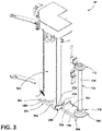
- the reference number 10 ( FIG. 1 ) generally designates a wrap machine of the present invention.
- the wrap machine 10 includes a base 14 having a rotatable arm 12 connected thereto.
- the wrap machine 10 further includes a carriage 24 vertically movable on the rotatable arm 12 for wrapping a product 28 on a pallet 32 located on the ground 30.
- the carriage 24 carries a roll of stretch wrap film 26a for wrapping the product 28 and could also be used for wrapping an upper end of the pallet 32.
- the present invention is drawn to the carriage 24, which can be used on any wrap machine 10, including a portable wrap machine as shown.
- An example of a portable wrap machine is disclosed in U.S. Patent Application No.
- the base 14 is movable and carriage 24 is moved about the product on the rotatable arm 12.
- the carriage 24 as disclosed herein can also be used in a wrap machine that does not have a movable base such that the product is moved to adjacent the base and the rotatable arm and carriage is rotated about the product to wrap the product.
- Such stationary wrap machines are well known to those skilled in the art.
- the carriage 24 as disclosed herein can be used with a wrap machine that includes a stationary column that has a carriage movable vertically thereon wherein the product is turned on a turntable to wrap the product.
- FIG. 2 illustrates a prior art carriage 50.
- the prior art carriage 50 includes a top support 52 and a base 54 having a main portion 66 with an upper surface 56.
- the prior art carriage 50 includes a pre-stretch assembly 58 including a plurality of rollers extending between the base 54 and the top support 52, including pre-stretch rollers 60, a diverter roller 62, a dancer roller 64, nip rollers (not shown) for holding film against the pre-stretch rollers 60 and idle rollers (not shown).
- the base 54 includes the main portion 66 supporting the pre-stretch assembly 58 and a source of stretch wrap extension platform 68 extending laterally from the main portion 66 of the base 54.
- the source of stretch wrap extension platform 68 includes a stretch wrap mandrel 70 extending upward vertically from an upper surface 72 of the source of stretch wrap extension platform 68 of the base 54.
- the upper surface 56 of the main portion 66 and the upper surface 72 of the source of stretch wrap extension platform 68 are level and contiguous.
- a roll of stretch wrap film 26 (shown in phantom in FIG. 2 ) comprising film 76 wrapped about a center tube 78 is inserted over the stretch wrap mandrel 70 with the mandrel 70 closely fitting within the tube 78 of the roll of stretch wrap film 26.
- the roll of stretch wrap film 26 comes to rest on the upper surface 72 of the source of stretch wrap extension platform 68 of the base 54.
- the film 76 of the roll of stretch wrap film 26 unrolls from the center tube 78 and is threaded through the pre-stretch assembly 58 to stretch the film 76 before the film 76 is wrapped about the product 28.
- the pre-stretch assembly 58 also includes a gear system (not shown in FIG.
- the upper surface 56 of the main portion 66 and the upper surface 72 of the source of stretch wrap extension platform 68 are level and contiguous such that the base 54 supports both the stretch wrap mandrel 70, the pre-stretch rollers 60 and the remaining rollers on a level plane.
- the center tube 78 along with the film 76 thereon of the roll of stretch wrap film 26 also rest on the upper surface 72 of the source of stretch wrap extension platform 68 of the base 54. Therefore, the film 76 from the roll of stretch wrap film 26 that enters the pre-stretch assembly 58 of the prior art carriage 50 is substantially parallel to the axes of rotation of the rollers of the pre-stretch assembly 58 and is flat without any creases.
- the carriage 24 of the present invention ( FIGS. 3-7 ) is substantially identical to the prior art carriage 50.
- identical parts from the prior art carriage 50 included in the carriage 24 of the present invention are represented by the same, corresponding reference number, except for the suffix "a" in the numerals of the FIGS. 3-7 .
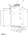
- the carriage 24 of the present invention allows for roping of a bottom portion 100 of the film 76a from the roll of stretch wrap film 26a that enters the pre-stretch assembly 58a, thereby creating a roped or creased area 102 at the bottom portion 100 of the film 76a(see FIG. 6 ).
- the illustrated carriage 24 of the present invention can provide for the roped or creased area 102 at the bottom portion 100 of the film 76a in several manners.
- the upper surface 72a of the source of stretch wrap extension platform 68a can be located below the upper surface 56a of the main portion 66a of the base 54a having the pre-stretch assembly 58a.
- the carriage 24 can include a film bottom roping bar 200 that engages the bottom portion 100 of the film 76a from the roll of stretch wrap film 26a before the film 76a enters the pre-stretch assembly 58a.
- the carriage 24 could include both the upper surface 72a of the source of stretch wrap extension platform 68a being lower than the upper surface 56a of the main portion 66a of the base 54a and the film bottom roping bar 200.
- the illustrated source of stretch wrap extension platform 68a of the base 54a includes a stretch wrap mandrel 70a for holding the roll of stretch wrap film 26a (see FIG. 6 ).
- the source of stretch wrap extension platform 68a can be any platform wherein the bottom of the film 76a leaving the roll of stretch wrap film 26a is located below the upper surface 56a of the main portion 66a of the base 54a.
- the source of stretch wrap extension platform 68a includes a plate 104 having the upper surface 72a.
- the plate 104 can be connected or formed from the base 54a of the carriage 24a and is configured such that the upper surface 72a is located below the upper surface 56a of the main portion 66a of the base 54a.
- the plate 104 can include strengthening flanges 106 extending downwardly from the edges of the plate 104 for strength.
- the stretch wrap mandrel 70a extends upward and perpendicularly from the plate 104 and is configured to hold the roll of stretch wrap film 26a thereon.
- the stretch wrap mandrel 70a includes a fixed post 108, a bottom wheel 110 and a top wheel 112.
- the bottom wheel 110 and the top wheel 112 are rotatable upon the fixed post 108.
- the bottom wheel 110 and the top wheel 112 have approximately the same diameter and are configured to closely receive the center tube 78a of the roll of stretch wrap film 26a to allow the roll of stretch wrap film 26a to easily rotate.
- the source of stretch wrap extension platform 68a of the base 54a having the upper surface 72a being lower than the upper surface 56a of the main portion 66a of the base 54a allows the bottom portion 100 of the film 76a to form the roped or creased area 102 as shown in FIG. 6 .
- the bottom portion 100 of the film 76a on the center tube 78 is directly adjacent or abutting the upper surface 72a of the source of stretch wrap extension platform 68a of the base 54a.
- the bottom portion 100 of the film 76a is moved upward to move over the upper surface 56a of the main portion 66a of the base 54a, thereby forming the roped or creased area 102.
- the bottom portion 100 of the film 76a could abut any surface between the upper surface 72a of the source of stretch wrap extension platform 68a of the base 54a and the upper surface 56a of the main portion 66a of the base 54a.
- such surface could be merely a ledge between the two upper surfaces 56a, 72a.
- the surface could also be on the film bottom roping bar 200.
- the film bottom roping bar 200 includes a primary plate portion 202 connected to the base 54a and an arm 204 that extends directly in the path between the roll of stretch wrap film 26a and the pre-stretch assembly 58a such that the bottom portion 100 of the film 76a is forced to form the roped or creased area 102.
- the arm 204 can be stationary (as shown) or can be pivotally connected to the primary plate portion 202 (and can have, for example, a circular cross-sectional shape (i.e., a roller)).
- the film bottom roping bar 200 could be the sole mechanism for forming the roped or creased area 102.
- the arm 204 of the film bottom roping bar 200 could force the bottom portion 100 of the film 76a upward to form the roped or creased area 102.
- the film bottom roping bar 200 could be made to be easily removable (e.g., through a wing nut connection) or could be made to be vertically adjustable to control the amount of the bottom portion 100 of the film 76a that is made into the roped or creased area 102.
- the source of stretch wrap extension platform 68a of the base 54a could be configured to be vertically adjustably connected to the main portion 66 of the base 54a to control the amount of the bottom portion 100 of the film 76a that is made into the roped or creased area 102.
- FIG. 7 illustrates a system for not forming the roped or creased area 102 when the film bottom roping bar 200 and/or the unlevel surfaces 56a, 72a are employed.
- a support disc 300 can be placed over the mandrel 70a before the roll of stretch wrap film 26a is over the mandrel 70a.
- the support disc 300 supports the center tube 78a and the rest of the roll of stretch wrap film 26a above the upper surface 72a of the source of stretch wrap extension platform 68a of the base 54a. Therefore, the bottom portion 100 of the film 76 does not form the roped or creased area 102 before entering the pre-stretch assembly 58a.
- the support disc 300 can be a closed ring inserted over the mandrel 70a, donut shaped to be allowed to be slid laterally onto the mandrel 70a (or selectively removed or added, for example, after the wrapping of the product has begun). It is further contemplated that the support disc 300 could be recessed into the source of stretch wrap extension platform 68a and either manually or automatically raised and lowered.
- the pre-stretch rollers 60a can include a cylindrical lower area 400 that is harder than the remaining portion of the pre-stretch rollers 60a and having the same diameter to ensure that the rope portion 102 of the film 76a does not permanently indent the grip face of the pre-stretch rollers 60a.
- the lower area 400 can be made of metal (e.g., aluminum).
- the carriage 24 can be tilted relative to the rotatable arm 12 and a ground surface 500 such that a dancer roller 502 (the last roller before the film 76a leaves the carriage 24) is closer to the ground 500 than the source of stretch wrap extension platform 68.
- a dancer roller 502 the last roller before the film 76a leaves the carriage 24
- the rope portion 102 can be wrapped about a product very close to the ground 500 and, if used, about a pallet holding the goods to be wrapped.
- the tilt also allows the source of stretch wrap extension platform 68 to be lower than the main portion 66a of the base 54a as outlined above.
Landscapes
- Engineering & Computer Science (AREA)
- Mechanical Engineering (AREA)
- Basic Packing Technique (AREA)
Applications Claiming Priority (1)
| Application Number | Priority Date | Filing Date | Title |
|---|---|---|---|
| US17/106,622 US20220169468A1 (en) | 2020-11-30 | 2020-11-30 | Stretch wrap film carriage |
Publications (1)
| Publication Number | Publication Date |
|---|---|
| EP4005935A1 true EP4005935A1 (de) | 2022-06-01 |
Family
ID=78332546
Family Applications (1)
| Application Number | Title | Priority Date | Filing Date |
|---|---|---|---|
| EP21203470.6A Withdrawn EP4005935A1 (de) | 2020-11-30 | 2021-10-19 | Wagen für dehnbare verpackungsfolie |
Country Status (2)
| Country | Link |
|---|---|
| US (1) | US20220169468A1 (de) |
| EP (1) | EP4005935A1 (de) |
Cited By (1)
| Publication number | Priority date | Publication date | Assignee | Title |
|---|---|---|---|---|
| CN118850410A (zh) * | 2024-09-26 | 2024-10-29 | 泰兴市图瑞包装有限公司 | 一种防尘缓冲袋自动包装机 |
Families Citing this family (2)
| Publication number | Priority date | Publication date | Assignee | Title |
|---|---|---|---|---|
| AT525393B1 (de) * | 2021-08-25 | 2023-08-15 | Mondi Ag | Vorrichtung, Anordnung und Verfahren zum Verpacken von Ladegut mit einer Papierbahn |
| IT202100029924A1 (it) * | 2021-11-26 | 2023-05-26 | Tosa S P A | Macchinario per avvolgere un articolo, avente un sistema di rinvio |
Citations (7)
| Publication number | Priority date | Publication date | Assignee | Title |
|---|---|---|---|---|
| US20060254225A1 (en) * | 2005-03-10 | 2006-11-16 | Lancaster Patrick R Iii | Stretch wrapping apparatus having film dispenser with pre-stretch assembly |
| US20090235617A1 (en) * | 2008-03-24 | 2009-09-24 | Moore Philip R | Wrapping apparatus having top loading and threading film dispenser |
| US7908830B2 (en) | 2007-10-12 | 2011-03-22 | Cousins Packaging Inc. | Carriage for a stretch wrapping machine |
| US20110067364A1 (en) * | 2009-09-22 | 2011-03-24 | Cousins Neil G | Carriage For A Stretch Wrapping Machine |
| US8166732B2 (en) | 2004-11-03 | 2012-05-01 | Cousins Packaging Inc. | Stretch wrap machine with top corner film transfer |
| US8549819B1 (en) * | 2006-10-11 | 2013-10-08 | Darrel Bison | Pallet roping and wrapping apparatus and method |
| US10183773B2 (en) * | 2014-10-31 | 2019-01-22 | Brenton Llc | Easy thread carriage for stretch film wrapping system |
Family Cites Families (13)
| Publication number | Priority date | Publication date | Assignee | Title |
|---|---|---|---|---|
| US4722170A (en) * | 1986-11-13 | 1988-02-02 | Lantech, Inc. | Upper guided lower driven stretch wrapping device |
| CA2457997A1 (en) * | 2003-02-18 | 2004-08-18 | Cousins Packaging Inc. | Stretch wrap threading device |
| FI116669B (fi) * | 2003-09-05 | 2006-01-31 | Haloila M Oy Ab | Käärintäkone |
| US20110179752A1 (en) * | 2010-01-22 | 2011-07-28 | Lantech.Com, Llc. | Demand throttle methods and apparatuses |
| US20220204198A1 (en) * | 2012-06-18 | 2022-06-30 | TAB Industries, LLC | Exhaust Blower for Orbital Pallet Wrappers |
| US20140208696A1 (en) * | 2013-01-25 | 2014-07-31 | Lantech.Com, Llc | Film Tension Apparatus And Supply Roll Support For Stretch Wrapping Machines |
| DE102014119204B4 (de) * | 2014-12-19 | 2020-03-26 | Windmöller & Hölscher Kg | Verfahren für die Anpassung zumindest eines Wickelparameters einer Wickelvorrichtung |
| US20160200467A1 (en) * | 2015-01-08 | 2016-07-14 | Neil G. Cousins | Portable stretch wrapping machine |
| US10696436B2 (en) * | 2017-03-13 | 2020-06-30 | John Ragsdale | System for management of automated stretch wrapping |
| US11643229B2 (en) * | 2019-09-12 | 2023-05-09 | Cousins Packaging Inc. | Portable wrapping machine |
| US11520026B2 (en) * | 2019-09-19 | 2022-12-06 | Lantech.Com, Llc | Ultrasonic packaging material flaw detection with time-limited response detection |
| US11434029B1 (en) * | 2020-04-03 | 2022-09-06 | Darrel Bison | Shipping pallet wrapping system |
| EP4008638B1 (de) * | 2020-12-02 | 2025-05-07 | A.C.M.I. - Societa' Per Azioni | Maschine und verfahren zum stabilisieren von palettierten lasten |
-
2020
- 2020-11-30 US US17/106,622 patent/US20220169468A1/en not_active Abandoned
-
2021
- 2021-10-19 EP EP21203470.6A patent/EP4005935A1/de not_active Withdrawn
Patent Citations (7)
| Publication number | Priority date | Publication date | Assignee | Title |
|---|---|---|---|---|
| US8166732B2 (en) | 2004-11-03 | 2012-05-01 | Cousins Packaging Inc. | Stretch wrap machine with top corner film transfer |
| US20060254225A1 (en) * | 2005-03-10 | 2006-11-16 | Lancaster Patrick R Iii | Stretch wrapping apparatus having film dispenser with pre-stretch assembly |
| US8549819B1 (en) * | 2006-10-11 | 2013-10-08 | Darrel Bison | Pallet roping and wrapping apparatus and method |
| US7908830B2 (en) | 2007-10-12 | 2011-03-22 | Cousins Packaging Inc. | Carriage for a stretch wrapping machine |
| US20090235617A1 (en) * | 2008-03-24 | 2009-09-24 | Moore Philip R | Wrapping apparatus having top loading and threading film dispenser |
| US20110067364A1 (en) * | 2009-09-22 | 2011-03-24 | Cousins Neil G | Carriage For A Stretch Wrapping Machine |
| US10183773B2 (en) * | 2014-10-31 | 2019-01-22 | Brenton Llc | Easy thread carriage for stretch film wrapping system |
Cited By (1)
| Publication number | Priority date | Publication date | Assignee | Title |
|---|---|---|---|---|
| CN118850410A (zh) * | 2024-09-26 | 2024-10-29 | 泰兴市图瑞包装有限公司 | 一种防尘缓冲袋自动包装机 |
Also Published As
| Publication number | Publication date |
|---|---|
| US20220169468A1 (en) | 2022-06-02 |
Similar Documents
| Publication | Publication Date | Title |
|---|---|---|
| EP4005935A1 (de) | Wagen für dehnbare verpackungsfolie | |
| US10023334B2 (en) | Full motion wrapping apparatus | |
| CA2738580C (en) | Method and apparatus for securing a load to a pallet with a roped film web | |
| US6360512B1 (en) | Machine and method for fastening a load | |
| US6688076B1 (en) | Apparatus for wrapping articles in film material | |
| US5016427A (en) | Film unwinding carriage for a packaging machine | |
| CA1310311C (en) | Apparatus for winding or unwinding a web of material | |
| JP3488720B2 (ja) | 垂直型発泡性包装材包装装置及びノーカーボンペーパーロールの包装方法 | |
| EP0378550B1 (de) | Filmspender | |
| NZ198287A (en) | Pre-stretching film web from feed stock and wrapping palletised load | |
| AU678940B2 (en) | Method and apparatus for wrapping elongate load having generally circular or generally annular ends | |
| US4502264A (en) | Film wrap machine | |
| US20110067364A1 (en) | Carriage For A Stretch Wrapping Machine | |
| AU603660B2 (en) | Device for unwinding a material web from a roll | |
| US20020174628A1 (en) | Method and apparatus for wrapping a load using variable roller stretch | |
| US4339093A (en) | Pneumatic roll lifter | |
| JPS6366075A (ja) | 巻取り機 | |
| US10375970B2 (en) | Apparatus and method for rolling sausage rolls | |
| CN215323430U (zh) | 一种管材绕膜包装设备 | |
| JP2963930B2 (ja) | 合成樹脂フイルムによる円筒状物品の自動包装装置 | |
| JPH0329715A (ja) | ストレッチ包装機 | |
| JP4223790B2 (ja) | ストレッチ包装機 | |
| CN112777027A (zh) | 一种管材绕膜包装设备 | |
| JPH0248082Y2 (de) | ||
| JP2002153914A (ja) | 加工材料の給送装置 |
Legal Events
| Date | Code | Title | Description |
|---|---|---|---|
| PUAI | Public reference made under article 153(3) epc to a published international application that has entered the european phase |
Free format text: ORIGINAL CODE: 0009012 |
|
| STAA | Information on the status of an ep patent application or granted ep patent |
Free format text: STATUS: THE APPLICATION HAS BEEN PUBLISHED |
|
| AK | Designated contracting states |
Kind code of ref document: A1 Designated state(s): AL AT BE BG CH CY CZ DE DK EE ES FI FR GB GR HR HU IE IS IT LI LT LU LV MC MK MT NL NO PL PT RO RS SE SI SK SM TR |
|
| STAA | Information on the status of an ep patent application or granted ep patent |
Free format text: STATUS: THE APPLICATION IS DEEMED TO BE WITHDRAWN |
|
| 18D | Application deemed to be withdrawn |
Effective date: 20221202 |