EP4005938A1 - Machine et procédé d'étiquettage avec commande automatique active de la tension de la bande - Google Patents
Machine et procédé d'étiquettage avec commande automatique active de la tension de la bande Download PDFInfo
- Publication number
- EP4005938A1 EP4005938A1 EP20210525.0A EP20210525A EP4005938A1 EP 4005938 A1 EP4005938 A1 EP 4005938A1 EP 20210525 A EP20210525 A EP 20210525A EP 4005938 A1 EP4005938 A1 EP 4005938A1
- Authority
- EP
- European Patent Office
- Prior art keywords
- web
- threshold
- feeding device
- tension
- controlling
- Prior art date
- Legal status (The legal status is an assumption and is not a legal conclusion. Google has not performed a legal analysis and makes no representation as to the accuracy of the status listed.)
- Withdrawn
Links
- 238000002372 labelling Methods 0.000 title claims abstract description 48
- 238000000034 method Methods 0.000 title claims abstract description 28
- 239000000463 material Substances 0.000 claims abstract description 25
- 230000001276 controlling effect Effects 0.000 claims description 57
- 230000003139 buffering effect Effects 0.000 claims description 23
- 230000003247 decreasing effect Effects 0.000 claims description 11
- 230000002596 correlated effect Effects 0.000 claims description 5
- 239000003292 glue Substances 0.000 description 8
- 238000004026 adhesive bonding Methods 0.000 description 6
- 238000010586 diagram Methods 0.000 description 6
- 230000001052 transient effect Effects 0.000 description 4
- 230000000694 effects Effects 0.000 description 2
- 238000011144 upstream manufacturing Methods 0.000 description 2
- 229910000831 Steel Inorganic materials 0.000 description 1
- XAGFODPZIPBFFR-UHFFFAOYSA-N aluminium Chemical compound [Al] XAGFODPZIPBFFR-UHFFFAOYSA-N 0.000 description 1
- 229910052782 aluminium Inorganic materials 0.000 description 1
- 239000011111 cardboard Substances 0.000 description 1
- 239000002131 composite material Substances 0.000 description 1
- 230000001419 dependent effect Effects 0.000 description 1
- 238000011156 evaluation Methods 0.000 description 1
- 239000011521 glass Substances 0.000 description 1
- 238000012986 modification Methods 0.000 description 1
- 230000004048 modification Effects 0.000 description 1
- 239000005022 packaging material Substances 0.000 description 1
- 239000011087 paperboard Substances 0.000 description 1
- 239000004033 plastic Substances 0.000 description 1
- 229920003023 plastic Polymers 0.000 description 1
- 239000010959 steel Substances 0.000 description 1
Images


Classifications
-
- B—PERFORMING OPERATIONS; TRANSPORTING
- B65—CONVEYING; PACKING; STORING; HANDLING THIN OR FILAMENTARY MATERIAL
- B65C—LABELLING OR TAGGING MACHINES, APPARATUS, OR PROCESSES
- B65C9/00—Details of labelling machines or apparatus
- B65C9/40—Controls; Safety devices
- B65C9/42—Label feed control
-
- B—PERFORMING OPERATIONS; TRANSPORTING
- B65—CONVEYING; PACKING; STORING; HANDLING THIN OR FILAMENTARY MATERIAL
- B65H—HANDLING THIN OR FILAMENTARY MATERIAL, e.g. SHEETS, WEBS, CABLES
- B65H20/00—Advancing webs
- B65H20/30—Arrangements for accumulating surplus web
- B65H20/32—Arrangements for accumulating surplus web by making loops
- B65H20/34—Arrangements for accumulating surplus web by making loops with rollers
-
- B—PERFORMING OPERATIONS; TRANSPORTING
- B65—CONVEYING; PACKING; STORING; HANDLING THIN OR FILAMENTARY MATERIAL
- B65H—HANDLING THIN OR FILAMENTARY MATERIAL, e.g. SHEETS, WEBS, CABLES
- B65H23/00—Registering, tensioning, smoothing or guiding webs
- B65H23/04—Registering, tensioning, smoothing or guiding webs longitudinally
- B65H23/18—Registering, tensioning, smoothing or guiding webs longitudinally by controlling or regulating the web-advancing mechanism, e.g. mechanism acting on the running web
- B65H23/188—Registering, tensioning, smoothing or guiding webs longitudinally by controlling or regulating the web-advancing mechanism, e.g. mechanism acting on the running web in connection with running-web
- B65H23/1888—Registering, tensioning, smoothing or guiding webs longitudinally by controlling or regulating the web-advancing mechanism, e.g. mechanism acting on the running web in connection with running-web and controlling web tension
-
- B—PERFORMING OPERATIONS; TRANSPORTING
- B65—CONVEYING; PACKING; STORING; HANDLING THIN OR FILAMENTARY MATERIAL
- B65C—LABELLING OR TAGGING MACHINES, APPARATUS, OR PROCESSES
- B65C9/00—Details of labelling machines or apparatus
- B65C2009/0081—Means for forming a label web buffer, e.g. label web loop
-
- B—PERFORMING OPERATIONS; TRANSPORTING
- B65—CONVEYING; PACKING; STORING; HANDLING THIN OR FILAMENTARY MATERIAL
- B65H—HANDLING THIN OR FILAMENTARY MATERIAL, e.g. SHEETS, WEBS, CABLES
- B65H2301/00—Handling processes for sheets or webs
- B65H2301/30—Orientation, displacement, position of the handled material
- B65H2301/31—Features of transport path
- B65H2301/311—Features of transport path for transport path in plane of handled material, e.g. geometry
- B65H2301/3112—S-shaped
-
- B—PERFORMING OPERATIONS; TRANSPORTING
- B65—CONVEYING; PACKING; STORING; HANDLING THIN OR FILAMENTARY MATERIAL
- B65H—HANDLING THIN OR FILAMENTARY MATERIAL, e.g. SHEETS, WEBS, CABLES
- B65H2408/00—Specific machines
- B65H2408/20—Specific machines for handling web(s)
- B65H2408/21—Accumulators
- B65H2408/217—Accumulators of rollers type, e.g. with at least one fixed and one movable roller
- B65H2408/2171—Accumulators of rollers type, e.g. with at least one fixed and one movable roller the position of the movable roller(s), i.e. the web loop, being positively actuated
-
- B—PERFORMING OPERATIONS; TRANSPORTING
- B65—CONVEYING; PACKING; STORING; HANDLING THIN OR FILAMENTARY MATERIAL
- B65H—HANDLING THIN OR FILAMENTARY MATERIAL, e.g. SHEETS, WEBS, CABLES
- B65H2408/00—Specific machines
- B65H2408/20—Specific machines for handling web(s)
- B65H2408/21—Accumulators
- B65H2408/217—Accumulators of rollers type, e.g. with at least one fixed and one movable roller
- B65H2408/2172—Accumulators of rollers type, e.g. with at least one fixed and one movable roller several cascaded loops of rollers
-
- B—PERFORMING OPERATIONS; TRANSPORTING
- B65—CONVEYING; PACKING; STORING; HANDLING THIN OR FILAMENTARY MATERIAL
- B65H—HANDLING THIN OR FILAMENTARY MATERIAL, e.g. SHEETS, WEBS, CABLES
- B65H2801/00—Application field
- B65H2801/75—Labelling machines
Definitions
- the present invention relates to a method for labelling a plurality of containers by means of respective portions of a web of labelling material, and to a machine configured for carrying out the method, wherein the method allows a more accurate control of the web tension.
- Labelling machines are known for labelling containers.
- the labelling machine comprises an advancement device for advancing the web according to an advancement direction.
- the advancement device comprises a web feeding device for feeding the web according to a feeding device parameter.
- the advancement device comprises a web buffering unit located downstream of the feeding device according to the advancement direction.
- the buffering unit comprises a first guide roller and a second guide roller distinct from the first guide roller.
- a spring is interposed between the rollers for influencing the position of the second roller with respect to the first roller, to control automatically in passive way the tension of the web downstream of the web feeding device.
- a labelling method allows to improve the precision and/or accuracy and/or the speed of the control of the web tension.
- a labelling machine according to any of the appended machine claims or according to present description is configured for carrying out a method according to any of the appended method claims or according to present description.
- the method is for labelling a plurality of containers 3 by means of respective portions 2 of a web 4 of labelling material.
- the method comprises advancing the web 4 of labelling material according to an advancement direction D1.
- the machine 1 comprises an advancement device 30 for carrying out said advancing.
- the advancing comprises, by means of a feeding device 8, feeding the web according to a feeding device parameter K.
- the feeding device parameter K is showed in Figure 3 .
- the machine 1 comprises the feeding device 8 for carrying out said feeding.
- the feeding device 8 is indicated in Figure 1 and in the block diagram of Figure 3 .
- Feeding device 8 comprises a support shaft rotatable around a rotation axis E.
- the shaft is for carrying a reel 26 carrying the web of labeling material 4.
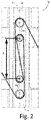
- the advancing comprises buffering the web 4 by means of at least one guide roller 30 guiding the advancing web 4.
- the at least one guide roller 30 is showed in Figure 2 .
- the machine 1 comprises a web buffering unit 10 for carrying out said buffering.
- the buffering unit 10 is showed in more detail in Figure 2 .
- Said buffering is carried out downstream of the feeding device 8 according to the advancement direction D1.
- the web buffering unit 10 is located downstream of the feeding device 8 according to the advancement direction D1.
- the method comprises automatically and actively controlling a position Y of the at least one guide roller 30, by means of at least a buffer motor BM influencing said position Y.
- the position Y is showed in Figure 2 .
- the buffer motor BM is indicated for the sake of convenience only in the block diagram of Figure 3 .
- the at least one guide roller 30 comprises a first guide roller and a second guide roller distinct from the first guide roller.
- the position Y is a distance between the first guide roller and the second guide roller.
- Each of said rollers is for guiding the advancing web 4.
- the first guide roller is supported by a first support 31 supporting the first guide roller.
- the second guide roller is supported by a second support 32 supporting the second guide roller.
- each of the first guide roller and second guide roller is indicated with 30.
- the first support 31 can be a first carriage carrying the first roller.
- the second support 32 can be a second carriage carrying the second roller.
- the buffer motor BM is mechanically interposed between the first support 31 and the second support 32, to influence the position Y.
- the first support 31 and the second support 32 are movable with respect to each other to allow said position Y to be changed or influenced by the buffer motor BM.
- the buffering unit 10 comprises the first support 31, the second support 32, the first roller and the second roller.
- the machine 1 comprises a position control system for carrying out said automatically and actively controlling the position Y.
- the position control system is indicated with the box PCS in Figure 3 .
- the position control system PCS comprises a buffer motor control unit BMCU and the buffer motor BM.
- the position control system PCS is configured so that the buffer motor control unit BMCU controls the buffer motor BM by means of a control variable.
- the control variable is represented by letter m in Figure 3 .
- the method comprises automatically detecting a resistance parameter Z.
- the resistance parameter Z is correlated to a tension of the web 4.
- the tension of the web 4 acts on the first guide roller and/or on the second guide roller, so that the resistance parameter Z is dependent upon or correlated to the tension of the web.
- the tension is downstream of the feeding device 8 according to the advancement direction D1.
- the machine 1 is configured so that an increase of the position Y produces an increase of the tension.
- the machine 1 is configured so that a decrease of the position Y produces a decrease of the tension.
- the method comprises controlling the tension. Controlling the tension is carried out by automatically and actively controlling the feeding device 8. Automatically and actively controlling the feeding device 8 comprises automatically and actively controlling the feeding device parameter K. Controlling the tension is carried out also by automatically and actively controlling the position control system PCS. Automatically and actively controlling the position control system PCS comprises automatically and actively controlling the automatically and actively controlling the position Y. Controlling the tension is carried out based at least on the detected resistance parameter Z.
- controlling the tension is carried out also by automatically and actively controlling the position control system PCS, and automatically and actively controlling the position control system PCS comprises automatically and actively controlling the automatically and actively controlling the position Y, controlling the tension is carried out based also at least on the position Y.
- the tension control system TCS actively and automatically controls the position control system PCS and the feeding device 8.
- the machine 1 comprises a tension control system for carrying out said controlling the tension.
- the tension control system is also for carrying out said detecting the resistance parameter Z.
- the tension control system is indicated with TCS in Figure 3 .
- the tension control system TCS comprises a tension control unit TCU.
- the feeding device parameter K can be a linear speed of the advancing web 4 or an angular speed of the shaft of the feeding device 8 or another parameter K influencing the feeding, and the variation of which can produce a variation of said tension.
- the tension of the web 4 is automatically controlled with higher precision, and/or with higher accuracy and/or with higher speed.
- the machine 1 is configured so that the higher the tension, the higher the resistance parameter Z, and so that the lower the tension, the lower the resistance parameter Z. Therefore, the machine 1 is configured so that the resistance parameter Z is directly proportional to the tension.
- the resistance parameter Z is indicative of a force or torque acting on the buffer motor BM. In this way it is increased the accuracy of controlling the tension as the resistance parameter Z, which is detected for controlling the tension, is strictly correlated with the same component, that is the buffer motor BM, which is used also for controlling the position Y, which position Y is another variable used for adjusting the tension together with the detected resistance parameter Z.
- a variation of the feeding device parameter K produces an effect or disturbance on the buffer motor BM.
- This effect or disturbance is represented by letter w in Figure 3 . Therefore also the position Y can be influenced by a variation of the feeding device parameter K.
- Controlling the tension is carried out based at least on a first threshold Z 1 and a second threshold Z 2 .
- the first threshold Z 1 and the second threshold Z 2 are preestablished.
- the second threshold Z 2 is greater than the first threshold Z 1 or equal to the first threshold Z 1 . If the second threshold Z 2 is equal to the first threshold Z 1 , the first threshold Z 1 and the second threshold Z 2 are not different from each other.
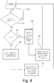
- the example flow diagram of Figure 4 is preferably referred to a situation in which the second threshold Z 2 is greater than the first threshold Z 1 . However, the example flow diagram of Figure 4 can be considered applicable also to a situation in which the first threshold Z 1 and the second threshold Z 2 are equal to each other.
- Actively and automatically controlling the feeding device parameter K is carried out by decreasing the feeding device parameter K if the detected resistance parameter Z is smaller than the first threshold Z 1 .
- the amplitude of the feeding device parameter K decrease is based on, for example directly proportional to, the difference between the first threshold Z 1 and the detected resistance parameter Z.
- the detecting of the resistance parameter Z is represented in Figure 4 by block S1.
- the evaluation about whether the detected resistance parameter Z is smaller than the first threshold Z 1 can be considered represented in Figure 4 globally by block S2 and block S3. It is to be noted that, in block S2, it is evaluated whether the detected resistance parameter Z falls within the range from first threshold Z 1 to second threshold Z 2 . If the detected resistance parameter Z falls within this range, the method returns to the detecting S1 of the resistance parameter Z. If the first threshold Z1 is equal to second threshold Z 2 , the falling of the detected resistance parameter Z within this range means that the detected resistance parameter Z is equal to the first threshold Z 1 and equal to the second threshold Z 2 .
- Decreasing the feeding device parameter K is represented in Figure 4 by block S6.
- the position Y is automatically and actively controlled in a closed loop way with a reference or setpoint variable Y 0 .
- the machine 1 is configured so that an increase of the feeding device parameter K produces a decrease of the tension, and a decrease of the feeding device parameter K produces an increase of the tension. Therefore, if the detected resistance parameter Z is less than the first threshold Z1, decreasing the feeding device parameter K produces a desired increase of the tension.
- the position control system PCS is actively and automatically controlled by controlling the reference variable Y 0 . Therefore, actively and automatically controlling the position Y is actively and automatically controlled by controlling the reference variable Y 0 .
- the tension control system TCS controls the position control system PCS by controlling the reference variable Y 0 on which the feedback control of the position control system PCS is based.
- the reference variable Y 0 is controlled by increasing the reference variable Y 0 if the detected resistance parameter Z is smaller than the first threshold Z 1 .
- the amplitude of the reference variable Y 0 increase is based on, for example directly proportional to, the difference between the first threshold Z1 and the detected resistance parameter Z.
- Increasing the reference variable Y 0 is represented in Figure 4 by block S7.
- increasing the reference variable Y 0 can allow the web tension, during the transient of the feeding device 8, to increase more than it would do without the increase of the reference variable Y 0 , and therefore can compensate the transient of the feeding device 8. In this way the controlling of the tension is quicker.
- Actively and automatically controlling the feeding device parameter K is carried out by increasing the feeding device parameter K if the detected resistance parameter Z is greater than the second threshold Z 2 .
- the amplitude of the feeding device parameter K increase is based on, for example directly proportional to, the difference between the detected resistance parameter Z and the second threshold Z 2 .
- the buffer unit 10 is located downstream of the feeding device 8 according to the feeding direction D1, increasing the feeding device parameter K produces a desired decrease of the tension.
- the reference variable Y 0 is controlled by decreasing the reference variable Y 0 if the detected resistance parameter Z is greater than the second threshold Z 2 .
- the amplitude of the reference variable Y 0 decrease is based on, for example directly proportional to, the difference between the detected resistance parameter Z and the second threshold Z 2 .
- decreasing the reference variable Y 0 can allow the web tension, during the transient of the feeding device 8, to decrease more than it would do without the decrease of the reference variable Y 0 , and therefore can compensate the transient of the feeding device 8. In this way the controlling of the tension is quicker.
- an excessive rise of the tension causes automatically a reduction of the position Y and an increase of the feeding device parameter K, thereby decreasing the tension very quickly and/or precisely.
- an excessive lowering of the tension causes automatically an increase of the position Y and a decrease of the feeding device parameter K, thereby increasing the tension.
- the tension control system TCS is configured for detecting the resistance parameter Z through the buffer motor BM.
- the tension control system TCS is configured so that said resistance parameter Z is detected by means of a resistance sensor which is a part of the buffer motor BM or which is not a part of the buffer motor BM.
- the position control system PCS is configured for detecting the position Y through the buffer motor BM.
- the position control system TCS is configured so that said position Y is detected by means of a position sensor which is a part of the buffer motor BM.
- the position sensor is not be part of the buffer motor BM.
- Position sensor could comprise an encoder coupled to buffer motor BM and/or a capacitive sensor and/or a position transducer or similar.
- the feeding device 8 in another not shown embodiment, can be located upstream of the buffering unit 10, with respect to the advancement direction D1.
- the resistance parameter Z in another not shown embodiment, is the tension.
- the resistance sensor is a tension sensor.
- Containers 3 may be bottles, jars, vessels, containers or the like, in particular being made of base components, like glass, paper or cardboard, plastics, aluminum, steel, multilayer packaging material and composites.
- the label sheets could also be of the heat-shrink type obtained from a respective web of labeling material or of the pressure sensitive type and, which are stuck on a base web.
- each pattern defines (the extension of) a respective label sheet 2.
- machine 1 comprises at least:
- labeling apparatus 7 comprises the advancement device 30.
- the advancement device 30 is configured to advance web 4 along an advancement path Q, in particular from an initial station 9 to and/or towards label application station 6.
- the buffering unit 10 is designed to buffer web 4, and in particular is arranged downstream from initial station 9 along web advancement path Q.
- labeling apparatus 7 may comprise:
- labeling apparatus 7 may comprise a gluing unit 18 designed to apply glue onto label sheets 2 and/or onto web of labeling material 4.
- cutting unit 15 may be designed to cut web of labeling material 4 so as to define respective leading edges 19 and respective trailing edges 20 of label sheets 2.
- cutting unit 15 defines the respective trailing edge 20 of one respective label sheet 2 and the respective leading edge 19 of the respective successive label sheet 2 (while it is still part of web of labeling material 4).
- Cutting unit 15 comprises at least one cutting knife 21 and a counter-element 22 designed to cooperate with one another for cutting web of labeling material 4 at cutting station 16.
- cutting unit 15 may comprise a cutting drum 23 rotatable around a rotation axis B, in particular having a vertical orientation, and carrying cutting knife 21.
- cutting unit 15 could comprise a laser for cutting web of labeling material 4 at cutting station 16.
- gluing unit 18 may be designed to apply glue onto label sheets 2 in the area of and/or at the respective leading edge 19 and the respective trailing edge 20.
- Gluing unit 18 is configured to apply glue onto label sheets 2, in particular at a glue application station interposed between cutting station 16 and label application station 6.
- gluing unit 18 may be designed to apply the glue onto label sheets 2 while label sheets 2 are advanced, in use, by transfer conveyor 17.
- Initial station 9 and labeling station 6 define a main advancement direction D1 of web of labeling material 4.
- the advancement device 30 comprises:
- feed roller 24 is arranged downstream from initial station 9, in particular also downstream from buffer unit 10, along advancement path Q.
- feed roller 24 is arranged upstream from cutting station 16 along advancement path Q.
- advancement device 30 may comprise an auxiliary roller 25, arranged adjacent, in particular tangential, to feed roller 24 for interposing, in use, web of labeling material 4 between auxiliary roller 28 and feed roller 24.
- feeding device 8 may comprise a support shaft rotatable around a rotation axis E, in particular being parallel to rotation axis C (i.e. having a (substantially) vertical orientation) and being designed to carry a reel 26 carrying web of labeling material 4, which is wound onto reel 26.
- the support shaft is arranged in the area of (at) initial station 9.
- Support shaft may be passively rotatable around rotation axis E (i.e. by means of the traction forces resulting from rotation of feed roller 24 around rotation axis C) for unwinding web of labeling material 4 from reel 26.
- feeding unit 8 may comprise a break system for acting on reel 26 and/or web of labeling material 4.
- Feeding device 8 may comprise a drive motor operatively coupled to the support shaft being designed to actively actuate a rotation of support shaft around rotation axis E and therewith also of reel 26 around rotation axis E.
- a drive motor may be designed to control the angular speed of reel 26 around rotation axis E.
- the feed roller 24 in an embodiment which is not shown and is different from the embodiment shown in Figure 1 , can be considered a part of the feeding device 8.
- the feeding device parameter K can be the angular speed of feed roller 24.
- the feeding device parameter K can be the advancement velocity of web of labeling material 4 and/or the angular speed of reel 26 and/or the operating parameters of the drive motor operatively coupled to feed roller 24.
- buffering unit 10 comprises at least one guide roller 30 and at least one (for example electrical) buffer motor BM operatively coupled to the at least one guide roller 30 and designed to control a position, in particular a desired position, of the at least one guide roller 30 for controlling the tension of web of labeling material 4, and in particular for also controlling a buffering capacity of buffering unit 10.
- buffer motor BM operatively coupled to the at least one guide roller 30 and designed to control a position, in particular a desired position, of the at least one guide roller 30 for controlling the tension of web of labeling material 4, and in particular for also controlling a buffering capacity of buffering unit 10.
- buffering unit 10 could comprise a support arm connected to one guide roller and the support arm being angularly moveable for modifying the position of the guide roller and thereby controlling the tension of web of labeling material 4, and in particular to also the buffering capacity.
- buffer motor BM is operatively coupled to the support arm and designed to angularly move the support arm for controlling the position of the guide roller.
- first support 31 and second support 32 are disposed along a linear axis F. Additionally, first support 31 and/or second support 32 are linearly moveable so as to allow for a modification of distance Y between first guide roller, supported by first support 31, and second guide roller, supported by second support 32.
- distance Y is determined with respect to and/or along linear axis F.
Landscapes
- Controlling Rewinding, Feeding, Winding, Or Abnormalities Of Webs (AREA)
Priority Applications (1)
| Application Number | Priority Date | Filing Date | Title |
|---|---|---|---|
| EP20210525.0A EP4005938A1 (fr) | 2020-11-30 | 2020-11-30 | Machine et procédé d'étiquettage avec commande automatique active de la tension de la bande |
Applications Claiming Priority (1)
| Application Number | Priority Date | Filing Date | Title |
|---|---|---|---|
| EP20210525.0A EP4005938A1 (fr) | 2020-11-30 | 2020-11-30 | Machine et procédé d'étiquettage avec commande automatique active de la tension de la bande |
Publications (1)
| Publication Number | Publication Date |
|---|---|
| EP4005938A1 true EP4005938A1 (fr) | 2022-06-01 |
Family
ID=73646109
Family Applications (1)
| Application Number | Title | Priority Date | Filing Date |
|---|---|---|---|
| EP20210525.0A Withdrawn EP4005938A1 (fr) | 2020-11-30 | 2020-11-30 | Machine et procédé d'étiquettage avec commande automatique active de la tension de la bande |
Country Status (1)
| Country | Link |
|---|---|
| EP (1) | EP4005938A1 (fr) |
Cited By (1)
| Publication number | Priority date | Publication date | Assignee | Title |
|---|---|---|---|---|
| CN116443640A (zh) * | 2023-06-15 | 2023-07-18 | 苏州江天包装科技股份有限公司 | 逐级分解式印刷制品的在线张力调节系统 |
Citations (3)
| Publication number | Priority date | Publication date | Assignee | Title |
|---|---|---|---|---|
| EP2711322A1 (fr) * | 2012-09-21 | 2014-03-26 | Sidel S.p.A. Con Socio Unico | Dispositif tampon pour manipuler un matériau sous la forme d'une toile |
| DE202014100204U1 (de) * | 2014-01-20 | 2015-04-22 | Krones Ag | Bandpuffer für Etikettenbänder |
| WO2018114077A1 (fr) * | 2016-12-23 | 2018-06-28 | Krones Ag | Dispositif d'étiquetage et procédé destinés à appliquer des étiquettes sur des récipients |
-
2020
- 2020-11-30 EP EP20210525.0A patent/EP4005938A1/fr not_active Withdrawn
Patent Citations (3)
| Publication number | Priority date | Publication date | Assignee | Title |
|---|---|---|---|---|
| EP2711322A1 (fr) * | 2012-09-21 | 2014-03-26 | Sidel S.p.A. Con Socio Unico | Dispositif tampon pour manipuler un matériau sous la forme d'une toile |
| DE202014100204U1 (de) * | 2014-01-20 | 2015-04-22 | Krones Ag | Bandpuffer für Etikettenbänder |
| WO2018114077A1 (fr) * | 2016-12-23 | 2018-06-28 | Krones Ag | Dispositif d'étiquetage et procédé destinés à appliquer des étiquettes sur des récipients |
Cited By (2)
| Publication number | Priority date | Publication date | Assignee | Title |
|---|---|---|---|---|
| CN116443640A (zh) * | 2023-06-15 | 2023-07-18 | 苏州江天包装科技股份有限公司 | 逐级分解式印刷制品的在线张力调节系统 |
| CN116443640B (zh) * | 2023-06-15 | 2023-09-05 | 苏州江天包装科技股份有限公司 | 逐级分解式印刷制品的在线张力调节系统 |
Similar Documents
| Publication | Publication Date | Title |
|---|---|---|
| JP7386605B2 (ja) | ペーパーウェブの切断又は穿孔をするための装置及び方法 | |
| US12600512B2 (en) | Method for controlling the position of a material web edge | |
| JP5508663B2 (ja) | 印刷物を自動的に裁断するための方法および装置 | |
| US20110230321A1 (en) | Method and device for producing container-like composite packagings | |
| EP2847115B1 (fr) | Organe de commande et système permettant d'entraîner en rotation un rouleau de matériau de manière apte à être commandée | |
| EP2450284A1 (fr) | Machine d'application d'une bande adhésive | |
| US20120251270A1 (en) | Book block finishing machine | |
| US8820238B2 (en) | Method and apparatus for controlling the cut register of a web-fed rotary press | |
| CN108883626A (zh) | 覆膜机和用于对至少一个材料覆膜的方法 | |
| EP3265386B1 (fr) | Dispositif permettant la compensation continue d'un étirement d'un film durant un tirage applicable sur des machines à emballer | |
| KR20130057457A (ko) | 웨브 기재를 프로세싱하는 유닛 보호 방법, 공급 스테이션, 및 패키징 유닛 제조 기계 | |
| KR20010024532A (ko) | 프로세싱 헤드들을 일치시키기 위한 방법 및 장치 | |
| US6350333B1 (en) | Laminator for corrugated paperboard sheets | |
| CN110435958B (zh) | 用于操作撕开条幅材的方法和设备 | |
| EP4005938A1 (fr) | Machine et procédé d'étiquettage avec commande automatique active de la tension de la bande | |
| JP2022535545A (ja) | プラスチックフィルムを供給するための供給ユニット | |
| EP1507726B1 (fr) | Dispositif et procede de regulation de la tension d'un materiau en bande | |
| CN101362564A (zh) | 用于在加工机上进行轴校正的方法以及加工机 | |
| CN1191178C (zh) | 生产有外皮的包装件的方法和装置 | |
| US12552628B2 (en) | Apparatus for cutting a material web into individual sheets with a web storage | |
| EP1448468B1 (fr) | Procede et dispositif pour bandes de defilement imprimees avec une imprimante rapide | |
| EP2723666B1 (fr) | Système et procédé de variation de la position d'un point de pincement | |
| JP2022529598A (ja) | 包装機においてプラスチックフィルムを供給するための供給ユニット | |
| EP4225682B1 (fr) | Dérouleur de produit à couche mince enroulé sur un rouleau, avec extraction facilitée du rouleau | |
| KR100954444B1 (ko) | 웹의 폭방향 위치 변위 제어장치 |
Legal Events
| Date | Code | Title | Description |
|---|---|---|---|
| PUAI | Public reference made under article 153(3) epc to a published international application that has entered the european phase |
Free format text: ORIGINAL CODE: 0009012 |
|
| STAA | Information on the status of an ep patent application or granted ep patent |
Free format text: STATUS: THE APPLICATION HAS BEEN PUBLISHED |
|
| AK | Designated contracting states |
Kind code of ref document: A1 Designated state(s): AL AT BE BG CH CY CZ DE DK EE ES FI FR GB GR HR HU IE IS IT LI LT LU LV MC MK MT NL NO PL PT RO RS SE SI SK SM TR |
|
| STAA | Information on the status of an ep patent application or granted ep patent |
Free format text: STATUS: REQUEST FOR EXAMINATION WAS MADE |
|
| 17P | Request for examination filed |
Effective date: 20220830 |
|
| RBV | Designated contracting states (corrected) |
Designated state(s): AL AT BE BG CH CY CZ DE DK EE ES FI FR GB GR HR HU IE IS IT LI LT LU LV MC MK MT NL NO PL PT RO RS SE SI SK SM TR |
|
| GRAP | Despatch of communication of intention to grant a patent |
Free format text: ORIGINAL CODE: EPIDOSNIGR1 |
|
| STAA | Information on the status of an ep patent application or granted ep patent |
Free format text: STATUS: GRANT OF PATENT IS INTENDED |
|
| RIC1 | Information provided on ipc code assigned before grant |
Ipc: B65H 23/188 20060101ALI20240426BHEP Ipc: B65H 20/34 20060101ALI20240426BHEP Ipc: B65C 9/42 20060101AFI20240426BHEP |
|
| INTG | Intention to grant announced |
Effective date: 20240513 |
|
| STAA | Information on the status of an ep patent application or granted ep patent |
Free format text: STATUS: THE APPLICATION IS DEEMED TO BE WITHDRAWN |
|
| 18D | Application deemed to be withdrawn |
Effective date: 20240914 |