EP4005947A1 - Bouton-poussoir multiple destiné à un récipient de stockage d'aliments sous vide présentant une soupape à vide - Google Patents
Bouton-poussoir multiple destiné à un récipient de stockage d'aliments sous vide présentant une soupape à vide Download PDFInfo
- Publication number
- EP4005947A1 EP4005947A1 EP20843686.5A EP20843686A EP4005947A1 EP 4005947 A1 EP4005947 A1 EP 4005947A1 EP 20843686 A EP20843686 A EP 20843686A EP 4005947 A1 EP4005947 A1 EP 4005947A1
- Authority
- EP
- European Patent Office
- Prior art keywords
- push button
- vacuum
- pressing
- support part
- container body
- Prior art date
- Legal status (The legal status is an assumption and is not a legal conclusion. Google has not performed a legal analysis and makes no representation as to the accuracy of the status listed.)
- Granted
Links
Images

Classifications
-
- B—PERFORMING OPERATIONS; TRANSPORTING
- B65—CONVEYING; PACKING; STORING; HANDLING THIN OR FILAMENTARY MATERIAL
- B65D—CONTAINERS FOR STORAGE OR TRANSPORT OF ARTICLES OR MATERIALS, e.g. BAGS, BARRELS, BOTTLES, BOXES, CANS, CARTONS, CRATES, DRUMS, JARS, TANKS, HOPPERS, FORWARDING CONTAINERS; ACCESSORIES, CLOSURES, OR FITTINGS THEREFOR; PACKAGING ELEMENTS; PACKAGES
- B65D51/00—Closures not otherwise provided for
- B65D51/16—Closures not otherwise provided for with means for venting air or gas
- B65D51/1672—Closures not otherwise provided for with means for venting air or gas whereby venting occurs by manual actuation of the closure or other element
- B65D51/1683—Closures not otherwise provided for with means for venting air or gas whereby venting occurs by manual actuation of the closure or other element by actuating a separate element in the container or closure
-
- A—HUMAN NECESSITIES
- A47—FURNITURE; DOMESTIC ARTICLES OR APPLIANCES; COFFEE MILLS; SPICE MILLS; SUCTION CLEANERS IN GENERAL
- A47J—KITCHEN EQUIPMENT; COFFEE MILLS; SPICE MILLS; APPARATUS FOR MAKING BEVERAGES
- A47J47/00—Kitchen containers, stands or the like, not provided for in other groups of this subclass; Cutting-boards, e.g. for bread
- A47J47/02—Closed containers for foodstuffs
-
- B—PERFORMING OPERATIONS; TRANSPORTING
- B65—CONVEYING; PACKING; STORING; HANDLING THIN OR FILAMENTARY MATERIAL
- B65D—CONTAINERS FOR STORAGE OR TRANSPORT OF ARTICLES OR MATERIALS, e.g. BAGS, BARRELS, BOTTLES, BOXES, CANS, CARTONS, CRATES, DRUMS, JARS, TANKS, HOPPERS, FORWARDING CONTAINERS; ACCESSORIES, CLOSURES, OR FITTINGS THEREFOR; PACKAGING ELEMENTS; PACKAGES
- B65D51/00—Closures not otherwise provided for
- B65D51/16—Closures not otherwise provided for with means for venting air or gas
-
- B—PERFORMING OPERATIONS; TRANSPORTING
- B65—CONVEYING; PACKING; STORING; HANDLING THIN OR FILAMENTARY MATERIAL
- B65D—CONTAINERS FOR STORAGE OR TRANSPORT OF ARTICLES OR MATERIALS, e.g. BAGS, BARRELS, BOTTLES, BOXES, CANS, CARTONS, CRATES, DRUMS, JARS, TANKS, HOPPERS, FORWARDING CONTAINERS; ACCESSORIES, CLOSURES, OR FITTINGS THEREFOR; PACKAGING ELEMENTS; PACKAGES
- B65D51/00—Closures not otherwise provided for
- B65D51/24—Closures not otherwise provided for combined or co-operating with auxiliary devices for non-closing purposes
-
- B—PERFORMING OPERATIONS; TRANSPORTING
- B65—CONVEYING; PACKING; STORING; HANDLING THIN OR FILAMENTARY MATERIAL
- B65D—CONTAINERS FOR STORAGE OR TRANSPORT OF ARTICLES OR MATERIALS, e.g. BAGS, BARRELS, BOTTLES, BOXES, CANS, CARTONS, CRATES, DRUMS, JARS, TANKS, HOPPERS, FORWARDING CONTAINERS; ACCESSORIES, CLOSURES, OR FITTINGS THEREFOR; PACKAGING ELEMENTS; PACKAGES
- B65D79/00—Kinds or details of packages, not otherwise provided for
- B65D79/005—Packages having deformable parts for indicating or neutralizing internal pressure-variations by other means than venting
- B65D79/0087—Packages having deformable parts for indicating or neutralizing internal pressure-variations by other means than venting the deformable part being located in a closure, e.g. in caps or lids
-
- B—PERFORMING OPERATIONS; TRANSPORTING
- B65—CONVEYING; PACKING; STORING; HANDLING THIN OR FILAMENTARY MATERIAL
- B65D—CONTAINERS FOR STORAGE OR TRANSPORT OF ARTICLES OR MATERIALS, e.g. BAGS, BARRELS, BOTTLES, BOXES, CANS, CARTONS, CRATES, DRUMS, JARS, TANKS, HOPPERS, FORWARDING CONTAINERS; ACCESSORIES, CLOSURES, OR FITTINGS THEREFOR; PACKAGING ELEMENTS; PACKAGES
- B65D81/00—Containers, packaging elements, or packages, for contents presenting particular transport or storage problems, or adapted to be used for non-packaging purposes after removal of contents
- B65D81/18—Containers, packaging elements, or packages, for contents presenting particular transport or storage problems, or adapted to be used for non-packaging purposes after removal of contents providing specific environment for contents, e.g. temperature above or below ambient
- B65D81/20—Containers, packaging elements, or packages, for contents presenting particular transport or storage problems, or adapted to be used for non-packaging purposes after removal of contents providing specific environment for contents, e.g. temperature above or below ambient under vacuum or superatmospheric pressure, or in a special atmosphere, e.g. of inert gas
- B65D81/2007—Containers, packaging elements, or packages, for contents presenting particular transport or storage problems, or adapted to be used for non-packaging purposes after removal of contents providing specific environment for contents, e.g. temperature above or below ambient under vacuum or superatmospheric pressure, or in a special atmosphere, e.g. of inert gas under vacuum
- B65D81/2038—Containers, packaging elements, or packages, for contents presenting particular transport or storage problems, or adapted to be used for non-packaging purposes after removal of contents providing specific environment for contents, e.g. temperature above or below ambient under vacuum or superatmospheric pressure, or in a special atmosphere, e.g. of inert gas under vacuum with means for establishing or improving vacuum
-
- F—MECHANICAL ENGINEERING; LIGHTING; HEATING; WEAPONS; BLASTING
- F16—ENGINEERING ELEMENTS AND UNITS; GENERAL MEASURES FOR PRODUCING AND MAINTAINING EFFECTIVE FUNCTIONING OF MACHINES OR INSTALLATIONS; THERMAL INSULATION IN GENERAL
- F16K—VALVES; TAPS; COCKS; ACTUATING-FLOATS; DEVICES FOR VENTING OR AERATING
- F16K1/00—Lift valves or globe valves, i.e. cut-off apparatus with closure members having at least a component of their opening and closing motion perpendicular to the closing faces
- F16K1/30—Lift valves or globe valves, i.e. cut-off apparatus with closure members having at least a component of their opening and closing motion perpendicular to the closing faces specially adapted for pressure containers
-
- A—HUMAN NECESSITIES
- A47—FURNITURE; DOMESTIC ARTICLES OR APPLIANCES; COFFEE MILLS; SPICE MILLS; SUCTION CLEANERS IN GENERAL
- A47J—KITCHEN EQUIPMENT; COFFEE MILLS; SPICE MILLS; APPARATUS FOR MAKING BEVERAGES
- A47J47/00—Kitchen containers, stands or the like, not provided for in other groups of this subclass; Cutting-boards, e.g. for bread
- A47J47/02—Closed containers for foodstuffs
- A47J47/04—Closed containers for foodstuffs for granulated foodstuffs
- A47J47/06—Closed containers for foodstuffs for granulated foodstuffs with arrangements for keeping fresh
-
- A—HUMAN NECESSITIES
- A47—FURNITURE; DOMESTIC ARTICLES OR APPLIANCES; COFFEE MILLS; SPICE MILLS; SUCTION CLEANERS IN GENERAL
- A47J—KITCHEN EQUIPMENT; COFFEE MILLS; SPICE MILLS; APPARATUS FOR MAKING BEVERAGES
- A47J47/00—Kitchen containers, stands or the like, not provided for in other groups of this subclass; Cutting-boards, e.g. for bread
- A47J47/02—Closed containers for foodstuffs
- A47J47/08—Closed containers for foodstuffs for non-granulated foodstuffs
- A47J47/10—Closed containers for foodstuffs for non-granulated foodstuffs with arrangements for keeping fresh
-
- B—PERFORMING OPERATIONS; TRANSPORTING
- B65—CONVEYING; PACKING; STORING; HANDLING THIN OR FILAMENTARY MATERIAL
- B65D—CONTAINERS FOR STORAGE OR TRANSPORT OF ARTICLES OR MATERIALS, e.g. BAGS, BARRELS, BOTTLES, BOXES, CANS, CARTONS, CRATES, DRUMS, JARS, TANKS, HOPPERS, FORWARDING CONTAINERS; ACCESSORIES, CLOSURES, OR FITTINGS THEREFOR; PACKAGING ELEMENTS; PACKAGES
- B65D25/00—Details of other kinds or types of rigid or semi-rigid containers
- B65D25/02—Internal fittings
- B65D25/04—Partitions
- B65D25/08—Partitions with provisions for removing or destroying, e.g. to facilitate mixing of contents
- B65D25/085—Partitions with provisions for removing or destroying, e.g. to facilitate mixing of contents the partition being in the form of a plug or the like which is dislodged by means of a plunger rod or the like pushing the plug down
Definitions
- the present invention relates to a multi-push button for a vacuum food storage container having a vacuum valve and, more specifically, relates to a multi-push button for a vacuum food storage container having a vacuum valve that is applied to a vacuum valve structure installed in a cover of the vacuum food storage container, which includes a container body having an opening and a cover having a vacuum valve structure for opening and closing the opening to maintain various kinds of food accommodated in the container body in a weak vacuum state and to prevent food spoilage for a long period of time and prolong the preservation period of food, thereby creating a weak multi-vacuum inside the container body and maintaining multiple airtight states for formation of a vacuum.
- a vacuum food storage container for storing food in a vacuum to maintain freshness thereof for a long period of time by preventing spoilage of food
- a container body for storing food and a cover to open and close the opening of the container body in which a one-way valve enabling inflow/outflow of air of the container body is installed in the cover so that a user presses the cover to create a weak vacuum inside the container body or opens the valve to release the weak vacuum state inside the container body.
- the Korean Utility Model Gazette (Publication No. Utility Model 1995-0002132/Publication Date, March 25, 1995 ) discloses an air inflow/outflow valve of a vacuum food storage container previously filed by the applicant of the present application.
- an airtightness-maintaining pipe having an air inflow/outflow hole is installed in a cover for opening and closing the container body to maintain airtightness with the hemispherical cover, thereby preventing outflow of air to the outside.
- the conventional airtightness-maintaining pipe described above is only an initial airtightness-maintaining pipe that evacuates the air from the interior of the container body through the air inflow/outflow hole using a pump to maintain the interior of the container body in a weak vacuum state, and introduces air through the air inflow/outflow hole by pressing a push button to release the vacuum state.
- FIG. 1 illustrates a vacuum storage container in Utility Model Application No. 20-2002-0004815 disclosed in the Korean Registered Utility Model Gazette (published on April 16, 2001 ) previously filed by the applicant of the present application.
- the conventional vacuum storage container has an airtight member having a hollow body detachably coupled to the boss part and a diaphragm-shaped extension flange extending in a radial direction on at least one surface of the hollow body, and includes a vacuum holding member having a disk-shaped main body received in a cover member having an airtight contact surface that comes into contact with the extension flange of the airtight member and an exposed bar extending from the main body such that at least a portion thereof is exposed to the outside through the through-hole of the cover member and rising and falling in the through-hole as the interior of the container body is evacuated and as the vacuum state thereof is released.
- the conventional vacuum storage container described above has problems as follows because the interior of the container body is maintained in a weak vacuum state only by the configuration of the airtight member and the vacuum holding member in contact with the upper surface of the airtight member.
- the airtight member is slightly abraded and damaged due to long-term use of the vacuum food storage container, washing the contaminated airtight member, and the like, thereby failing to provide a contact surface for airtightness and causing inflow/outflow of air therethrough, so it is difficult to maintain a weak vacuum state inside the container body.
- a minute gap is generated between the airtight member and the vacuum holding member in contact with the upper surface of the airtight member for airtightness due to the gas pressure caused by the gas generated according to the oxidation of the food contained in the vacuum food storage container, and if air is introduced into the container body therethrough, the weak vacuum state inside the container body is also released, which causes the food contained in the container body to deteriorate and makes long-term storage impossible, thereby losing its value as a vacuum food container.
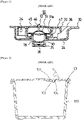
- FIG. 2 illustrates a cross-sectional view of a conventional container for a microwave oven.
- the cover 101 for opening and closing the opening of the container body 100 is provided with an opening/closing plate 103 and a steam discharge hole 104 for discharging the steam generated inside the container body when the container is in the microwave oven for cooking, and the opening/closing plate has a protrusion 102 formed to open and close the steam discharge hole 104.
- the protrusion 102 formed on the opening/closing plate 103 merely serves to discharge the steam generated from the food contained in the container body to the outside of the container body when the container is heated in the microwave oven, and is not intended to propose configuration capable of forming a vacuum state or releasing the vacuum state inside the container.
- the vacuum container for storing food it is required to propose a structure of a vacuum valve for improved vacuum maintenance and airtight maintenance to continuously maintain a weak vacuum state inside the container body in order to prevent spoilage of food for a long period of time and maintain freshness thereof for a long period of time.
- an objective of the present invention is to provide a multi-push button for a vacuum food storage container having a vacuum valve equipped with a push button that comes into contact with the upper surface of an airtight member or a boss part installed in the existing cover, as shown in FIG.
- a multi-push button for a vacuum food storage container having a vacuum valve including a push button that includes: a circular flange and a support part provided on the bottom surface of the flange; a thin height-varying part formed to protrude upwards by a predetermined height from the surface of the support part inside the outer diameter of the support part; a pressing part positioned on the upper surface of the height-varying part; and a circular airtightness-maintaining rod protruding downwards from the inner side of the pressing part, which is the inner center of the height-varying part, by a predetermined length with a space in the circumferential direction, and moving vertically downwards by pressing the pressing part, wherein the push button is formed of any one selected from among soft synthetic resin and soft silicone.
- the push button including a constant-thickness portion of the support part is formed of any one selected from among soft synthetic resin and soft silicone, and a thickness portion of the support part is any one selected from among a configuration in which solid silicone is compressed and bonded and a configuration in which a solid synthetic resin is double-injected onto the upper surface of the constant-thickness portion.
- a multi-push button for a vacuum food storage container having a vacuum valve which includes: a circular flange and a support part provided on the bottom surface of the flange, and a protruding annular rim protruding downwards from the outer circumference of the support part; a thin height-varying part formed to protrude upwards by a predetermined height from the surface of the support part inside the outer diameter of the support part; a pressing part positioned on the upper surface of the height-varying part; a guide groove for linear movement of the pressing part formed to be recessed downwards in a portion where an outer circumferential end portion of the pressing part and an upper end of the height-varying part come into contact with each other; and a circular airtightness-maintaining rod protruding downwards from the inner side of the pressing part, which is the inner center of the height-varying part, by a predetermined length with a space in the circumferential direction, and moving vertically downwards by pressing the
- the present invention has the effects of preventing the inflow/outflow of air even in the slightest abrasion or damage caused by cleaning the airtight member and preventing the inflow/outflow of air even if a minute gap is formed due to torsion of the airtight member by the impact to the cover. Furthermore, even if a minute gap is formed due to torsion of the airtight member by the impact to the cover. Furthermore, even if a minute gap is
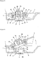
- FIG. 3 is a cross-sectional view of the vacuum valve showing the installation and operation state of a push button according to the present invention
- FIG. 4 is a cross-sectional view showing the state in which a push button according to the present invention is opened by rotation of a rotation cover
- FIG. 5 is a cutaway view showing the internal structure of a part of the push button according to the first embodiment of the present invention
- FIG. 6 is a cross-sectional view showing another embodiment of a push button according to the present invention.
- a vacuum food container to be used with a push button 30 is configured to include a container body (not shown) having an opening and a cover 1 to close the opening of the container body.
- a recess 2 is formed on the plate surface of a normal cover 1, and a boss part 4 having an air passing hole 3 for communicating the interior 40 of the container body and the outside is formed on the bottom of the recess.
- An airtight member 5 formed of soft silicone and having an airtightness-maintaining wing 5a and an air inflow/outflow hole 5b is installed in the general boss part 4 disclosed in the present invention.
- a rotation cover 7, having a predetermined accommodation portion 6, for opening and closing the airtight member 5 is rotatably installed in the recess 2 by a hinge 7a, and a cover member 10 having a through-hole 9 formed on the plate surface thereof is detachably coupled to the accommodation portion 8 of the rotation cover, and a push button 30, according to the present invention, formed of any one selected from among soft synthetic resin and soft silicone is provided inside the cover member 10.
- the push button 30 has a support part 32 configured as a circular flange 31 and a protruding annular rim 32c installed to protrude downwards from the outer circumference of the support part 32, and a thin height-varying part 33 is formed to protrude upwards by a certain height from the surface of the support part inside the outer diameter of the support part 32 and a pressing part 34 is formed on the upper surface of the height-varying part 33.
- a guide groove for linear movement of the pressing part 33a is formed to be recessed downwards in a portion where the outer circumferential end portion of the pressing part 34 and the upper end of the height-varying part 33 come into contact with each other.
- a circular airtightness-maintaining rod 36 is formed to protrude downwards in the vertical direction from the inner side of the pressing part 34, which is the inner center of the height-varying part 33 according to the present invention, and an annular locking jaw 37 is formed in the lower region of the airtightness-maintaining rod.
- a space 35 is formed in the circumferential direction between the airtightness-maintaining rod 36 and the height-varying part 33, and when the pressing part 34 is pressed by the user, the pressing part 34 is guided by the guide groove for linear movement of the pressing part 33a, which is formed to be recessed downwards in the portion where the outer circumferential end portion of the pressing part 34 and the upper end of the height-varying part 33 come into contact with each other, to be folded into the space 35 together with the height-varying part 33 so as to be rolled up therein and moved vertically downwards as shown in FIG. 2 .
- the height-varying part 33 is configured as a thin cylindrical wall
- the height-varying part 33 may be configured as a structure capable of being rolled up or folded with the downward movement of the height-varying part 33 by pressing the pressing part 34, that is, a corrugated pipe in which multiple corrugations are formed along the circumferential direction of the outer wall or a form similar to the corrugated pipe, thereby playing the role of the height-varying part 33 according to the present invention.
- the support part 32 formed on the bottom surface of the push button 30 comes into contact with the upper surface of the general airtight member 5 fitted to the boss part 4, as shown in FIG. 1 , to maintain the airtight state.
- the push button 30 according to the present invention can be used so that the support part 32 formed on the bottom of the push button 30 comes into direct contact with the upper surface of the boss part 4 without the airtight member 5 to maintain the airtight state.
- the air in the interior 40 of the container body pushes the amount of air corresponding to the downward movement of the cover upwards to be discharged through the air inflow/outflow hole 5b, and at the same time, when the pressing of the cover 1 is finished, the support part 32 of the push button 30 is in airtight contact with the airtightness-maintaining wing 5a to form a primary vacuum state in the interior 40 of the container body.
- the airtightness-maintaining rod 36 moves vertically downwards to be inserted into the air inflow/outflow hole 5b so that the amount of remaining air corresponding to the movement thereof is discharged through the air inflow/outflow hole 5b from the interior of the container body, and at the same time, when the pressing operation of the pressing part 34 is finished, a secondary vacuum state is formed between the bottom surface of the push button 30 and the upper surface of the airtight member 5.
- the present invention enables the container to maintain multiple airtight states by primarily preventing outflow of the air in the interior 40 of the container body by the airtightness-maintaining rod 40 that airtightly closes the air inflow/outflow hole 5b and by secondarily preventing outflow of the air through airtightness by the contact and suction adhesion between the bottom surface of the support part 32 of the push button 30 and the airtightness-maintaining wing 5a of the airtight member 5.
- the annular locking jaw 37 formed on the airtightness-maintaining rod 36 is deeply inserted into the air inflow/outflow hole 5b and is caught on the bottom surface of the air inflow/outflow hole 5b so as to prevent the airtightness-maintaining rod 36 from escaping itself from the air inflow/outflow hole 5b.
- the cover 1 in the case of forming a weak vacuum in the interior 40 of the container body again, the cover 1 is pressed with a palm after rotating the normal rotation cover 7 downwards to the original position such that the support part 32 of the push button 30 comes into airtight contact with the airtightness-maintaining wing 5a of the airtight member 5, and the pressing part 34 is pressed with a finger to maintain multiple airtight states in the interior 40 of the container body, thereby maintaining a weak vacuum state.
- the air in the interior 40 of the container body is discharged through the opening of the boss part 4, and at the same time, when the pressing of the cover 1 is finished, the support part 32 of the push button 30 is in airtight contact with the upper surface of the boss part 4 to form a primary vacuum state in the interior 40 of the container body.
- the airtightness-maintaining rod 36 is vertically inserted into the air inflow/outflow hole (not shown), which is formed in a diaphragm inside the boss part 4, so that the remaining air in the interior of the container body is discharged through the air inflow/outflow hole, and at the same time, when the pressing operation of the pressing part 34 is finished, a secondary vacuum state is formed between the bottom surface of the push button 30 and the upper surface of the boss part 4.
- the airtightness-maintaining rod 36 continues to move vertically downwards to be deeply inserted into the air inflow/outflow hole so that the remaining air is discharged through the air inflow/outflow hole by the airtightness-maintaining rod 36 to maintain a weak vacuum state, which is a tertiary vacuum state, in the interior 40 of the container body.
- the present invention enables the container to maintain multiple airtight states by primarily preventing outflow of the air in the interior 40 of the container body by the airtightness-maintaining rod 40 that airtightly closes the air inflow/outflow hole and by secondarily preventing outflow of the air through airtightness by the contact and suction adhesion between the bottom surface of the support part 32 of the push button 30 and the upper surface of the boss part 4.
- the cover 1 in the case of forming a weak vacuum in the interior 40 of the container body again, the cover 1 is pressed with the palm after rotating the normal rotation cover 7 downwards to the original position such that the support part 32 of the push button 30 comes into airtight contact with the upper surface of the boss part 4, and the pressing part 34 is pressed with a finger to maintain multiple airtight states in the interior 40 of the container body, thereby maintaining a weak vacuum state.
- the push button 30 including a constant-thickness portion 32a of the support part 32 is formed of any one selected from among soft synthetic resin and soft silicone, and a thickness portion 32b of the support part further includes any one selected from among a configuration in which solid silicone that is unable to be folded is compressed and bonded and a configuration in which a solid synthetic resin is double-injected onto the upper surface of the constant-thickness portion 32a. Therefore, since the thickness portion 32b of the support part 32 does not undergo shape deformation when the normal rotation cover 7 is lifted, the flange 31 is prevented from being folded upwards and separated from the accommodation portion 8.
- the present invention has the effects of preventing the inflow/outflow of air even in the slightest abrasion or damage caused by cleaning the airtight member and preventing the inflow/outflow of air even if a minute gap is formed due to torsion of the airtight member by the impact to the
Landscapes
- Engineering & Computer Science (AREA)
- Mechanical Engineering (AREA)
- Food Science & Technology (AREA)
- General Engineering & Computer Science (AREA)
- Closures For Containers (AREA)
- Packging For Living Organisms, Food Or Medicinal Products That Are Sensitive To Environmental Conditiond (AREA)
- Packages (AREA)
- Thermally Insulated Containers For Foods (AREA)
Applications Claiming Priority (2)
| Application Number | Priority Date | Filing Date | Title |
|---|---|---|---|
| KR1020190088814A KR102116905B1 (ko) | 2019-07-23 | 2019-07-23 | 진공밸브를 갖는 식품 진공보관 용기용 멀티 푸시버튼 |
| PCT/KR2020/008302 WO2021015434A1 (fr) | 2019-07-23 | 2020-06-25 | Bouton-poussoir multiple destiné à un récipient de stockage d'aliments sous vide présentant une soupape à vide |
Publications (4)
| Publication Number | Publication Date |
|---|---|
| EP4005947A1 true EP4005947A1 (fr) | 2022-06-01 |
| EP4005947A4 EP4005947A4 (fr) | 2023-08-16 |
| EP4005947B1 EP4005947B1 (fr) | 2026-01-07 |
| EP4005947C0 EP4005947C0 (fr) | 2026-01-07 |
Family
ID=71083231
Family Applications (1)
| Application Number | Title | Priority Date | Filing Date |
|---|---|---|---|
| EP20843686.5A Active EP4005947B1 (fr) | 2019-07-23 | 2020-06-25 | Bouton-poussoir multiple destiné à un récipient de stockage d'aliments sous vide présentant une soupape à vide |
Country Status (5)
| Country | Link |
|---|---|
| US (1) | US12466621B2 (fr) |
| EP (1) | EP4005947B1 (fr) |
| JP (1) | JP7385730B2 (fr) |
| KR (1) | KR102116905B1 (fr) |
| WO (1) | WO2021015434A1 (fr) |
Families Citing this family (2)
| Publication number | Priority date | Publication date | Assignee | Title |
|---|---|---|---|---|
| KR102116905B1 (ko) * | 2019-07-23 | 2020-06-01 | 왕수정 | 진공밸브를 갖는 식품 진공보관 용기용 멀티 푸시버튼 |
| KR20250151731A (ko) * | 2024-04-15 | 2025-10-22 | (주)네오플램 | 커버용 개폐조절부를 갖는 밀폐 용기 |
Family Cites Families (16)
| Publication number | Priority date | Publication date | Assignee | Title |
|---|---|---|---|---|
| KR970003746B1 (ko) | 1993-06-25 | 1997-03-21 | 기아정보시스템 주식회사 | 레이저 세기 자동 조절 시스템 |
| US20040040961A1 (en) * | 2000-12-08 | 2004-03-04 | Montserrat Vilalta | Food storage containers |
| US6557462B1 (en) * | 2001-12-28 | 2003-05-06 | Wang Soo Chang | Combined vacuum valve and vacuum indicator |
| JP4250438B2 (ja) * | 2003-03-05 | 2009-04-08 | サクラ精機株式会社 | 密閉用パッキン及び密閉容器 |
| KR200363285Y1 (ko) * | 2004-06-25 | 2004-10-02 | 김철규 | 음식물보관용 밀폐용기 |
| US20060032852A1 (en) * | 2004-08-12 | 2006-02-16 | Cai Edward Z | Airtight lid for container and method of use |
| KR100648004B1 (ko) | 2005-11-01 | 2006-11-23 | 하나코비 주식회사 | 진공밸브 작동식의 밀폐 용기 뚜껑 |
| KR101133979B1 (ko) * | 2008-12-30 | 2012-04-12 | 박준영 | 진공용기 뚜껑과 이를 위한 체크밸브 및 패킹 |
| US7874420B2 (en) * | 2009-02-09 | 2011-01-25 | Darren Coon | Affixable dispensing capsule |
| KR101448829B1 (ko) * | 2013-07-15 | 2014-10-13 | 강성일 | 내용물 배출펌프 |
| KR101524412B1 (ko) * | 2014-09-24 | 2015-05-29 | 이상규 | 진공과 밀폐를 선택적으로 사용하는 체크밸브가 구비된 밀폐용기 |
| TWM531237U (zh) * | 2016-07-05 | 2016-11-01 | 鑫宏益科技有限公司 | 密封保鮮容器 |
| US10562690B2 (en) * | 2017-02-07 | 2020-02-18 | Sunbeam Products, Inc. | Valve assembly for a food storage container |
| KR20190088814A (ko) | 2018-01-19 | 2019-07-29 | 박진규 | 애완동물 운동기구 |
| KR102116905B1 (ko) * | 2019-07-23 | 2020-06-01 | 왕수정 | 진공밸브를 갖는 식품 진공보관 용기용 멀티 푸시버튼 |
| US11267620B1 (en) * | 2021-07-15 | 2022-03-08 | Ningbo Halson Import & Export Co., Ltd. | Press type sealable container |
-
2019
- 2019-07-23 KR KR1020190088814A patent/KR102116905B1/ko active Active
-
2020
- 2020-06-25 US US17/625,035 patent/US12466621B2/en active Active
- 2020-06-25 EP EP20843686.5A patent/EP4005947B1/fr active Active
- 2020-06-25 WO PCT/KR2020/008302 patent/WO2021015434A1/fr not_active Ceased
- 2020-06-25 JP JP2022502241A patent/JP7385730B2/ja active Active
Also Published As
| Publication number | Publication date |
|---|---|
| WO2021015434A1 (fr) | 2021-01-28 |
| EP4005947A4 (fr) | 2023-08-16 |
| EP4005947B1 (fr) | 2026-01-07 |
| EP4005947C0 (fr) | 2026-01-07 |
| JP7385730B2 (ja) | 2023-11-22 |
| US12466621B2 (en) | 2025-11-11 |
| JP2022541437A (ja) | 2022-09-26 |
| KR102116905B1 (ko) | 2020-06-01 |
| US20220258933A1 (en) | 2022-08-18 |
Similar Documents
| Publication | Publication Date | Title |
|---|---|---|
| EP1447037B1 (fr) | Recipient à vide pour la conservation d'aliments | |
| US9096365B2 (en) | Vacuum generating apparatus and vacuum container provided with the same | |
| US5405038A (en) | Vacuum food container device | |
| US7621416B2 (en) | Cover of a container, especially of a vacuum receptacle for storage of foodstuffs | |
| EP4005947A1 (fr) | Bouton-poussoir multiple destiné à un récipient de stockage d'aliments sous vide présentant une soupape à vide | |
| US4657161A (en) | A Dispensing container for cream-like fluids | |
| JP3194876U (ja) | 真空保存容器 | |
| KR20150010306A (ko) | 크림타입 화장품 용기 | |
| WO2013164482A2 (fr) | Contenant | |
| KR20010071438A (ko) | 에어로졸 분말 밸브 | |
| KR20130025932A (ko) | 내부압력 자동배출 기능을 갖춘 식품용기용 밀폐뚜껑 | |
| KR20080014536A (ko) | 다용도 진공용기 뚜껑 | |
| EP4269272A3 (fr) | Récipient, fermeture et procédés de fabrication | |
| KR200472089Y1 (ko) | 밀폐용기 | |
| KR102134722B1 (ko) | 용기뚜껑에 결합되는 밀폐패킹 | |
| KR20020001732A (ko) | 용기 덮개 | |
| KR101114434B1 (ko) | 진공 패킹이 설치된 진공 용기 | |
| KR200311423Y1 (ko) | 공기배출수단을 갖는 진공식품용기 | |
| US3282474A (en) | Piston type aerosol unit | |
| KR101863201B1 (ko) | 진공 텀블러 | |
| KR101511661B1 (ko) | 진공용기용 체크밸브 어셈블리 | |
| KR102372050B1 (ko) | 진공보관함 | |
| KR200240733Y1 (ko) | 진공 용기 | |
| KR200253340Y1 (ko) | 진공용기 | |
| KR200391522Y1 (ko) | 진공용기 |
Legal Events
| Date | Code | Title | Description |
|---|---|---|---|
| STAA | Information on the status of an ep patent application or granted ep patent |
Free format text: STATUS: THE INTERNATIONAL PUBLICATION HAS BEEN MADE |
|
| PUAI | Public reference made under article 153(3) epc to a published international application that has entered the european phase |
Free format text: ORIGINAL CODE: 0009012 |
|
| STAA | Information on the status of an ep patent application or granted ep patent |
Free format text: STATUS: REQUEST FOR EXAMINATION WAS MADE |
|
| 17P | Request for examination filed |
Effective date: 20220210 |
|
| AK | Designated contracting states |
Kind code of ref document: A1 Designated state(s): AL AT BE BG CH CY CZ DE DK EE ES FI FR GB GR HR HU IE IS IT LI LT LU LV MC MK MT NL NO PL PT RO RS SE SI SK SM TR |
|
| DAV | Request for validation of the european patent (deleted) | ||
| DAX | Request for extension of the european patent (deleted) | ||
| TPAC | Observations filed by third parties |
Free format text: ORIGINAL CODE: EPIDOSNTIPA |
|
| A4 | Supplementary search report drawn up and despatched |
Effective date: 20230717 |
|
| RIC1 | Information provided on ipc code assigned before grant |
Ipc: A47J 47/10 20060101ALI20230711BHEP Ipc: A47J 47/06 20060101ALI20230711BHEP Ipc: A47J 47/02 20060101ALI20230711BHEP Ipc: F16K 1/30 20060101ALI20230711BHEP Ipc: B65D 51/24 20060101ALI20230711BHEP Ipc: B65D 51/16 20060101ALI20230711BHEP Ipc: B65D 81/20 20060101AFI20230711BHEP |
|
| STAA | Information on the status of an ep patent application or granted ep patent |
Free format text: STATUS: EXAMINATION IS IN PROGRESS |
|
| 17Q | First examination report despatched |
Effective date: 20240514 |
|
| GRAP | Despatch of communication of intention to grant a patent |
Free format text: ORIGINAL CODE: EPIDOSNIGR1 |
|
| STAA | Information on the status of an ep patent application or granted ep patent |
Free format text: STATUS: GRANT OF PATENT IS INTENDED |
|
| INTG | Intention to grant announced |
Effective date: 20250801 |
|
| GRAS | Grant fee paid |
Free format text: ORIGINAL CODE: EPIDOSNIGR3 |
|
| GRAA | (expected) grant |
Free format text: ORIGINAL CODE: 0009210 |
|
| STAA | Information on the status of an ep patent application or granted ep patent |
Free format text: STATUS: THE PATENT HAS BEEN GRANTED |
|
| AK | Designated contracting states |
Kind code of ref document: B1 Designated state(s): AL AT BE BG CH CY CZ DE DK EE ES FI FR GB GR HR HU IE IS IT LI LT LU LV MC MK MT NL NO PL PT RO RS SE SI SK SM TR |
|
| REG | Reference to a national code |
Ref country code: CH Ref legal event code: F10 Free format text: ST27 STATUS EVENT CODE: U-0-0-F10-F00 (AS PROVIDED BY THE NATIONAL OFFICE) Effective date: 20260107 Ref country code: GB Ref legal event code: FG4D |
|
| REG | Reference to a national code |
Ref country code: DE Ref legal event code: R096 Ref document number: 602020065286 Country of ref document: DE |
|
| REG | Reference to a national code |
Ref country code: IE Ref legal event code: FG4D |
|
| U01 | Request for unitary effect filed |
Effective date: 20260107 |
|
| U07 | Unitary effect registered |
Designated state(s): AT BE BG DE DK EE FI FR IT LT LU LV MT NL PT RO SE SI Effective date: 20260112 |