EP4005949B1 - Warehouse shuttle - Google Patents
Warehouse shuttle Download PDFInfo
- Publication number
- EP4005949B1 EP4005949B1 EP20863015.2A EP20863015A EP4005949B1 EP 4005949 B1 EP4005949 B1 EP 4005949B1 EP 20863015 A EP20863015 A EP 20863015A EP 4005949 B1 EP4005949 B1 EP 4005949B1
- Authority
- EP
- European Patent Office
- Prior art keywords
- component
- transmission wheel
- blocking component
- plate
- transmission
- Prior art date
- Legal status (The legal status is an assumption and is not a legal conclusion. Google has not performed a legal analysis and makes no representation as to the accuracy of the status listed.)
- Active
Links
Images




Classifications
-
- B—PERFORMING OPERATIONS; TRANSPORTING
- B65—CONVEYING; PACKING; STORING; HANDLING THIN OR FILAMENTARY MATERIAL
- B65G—TRANSPORT OR STORAGE DEVICES, e.g. CONVEYORS FOR LOADING OR TIPPING, SHOP CONVEYOR SYSTEMS OR PNEUMATIC TUBE CONVEYORS
- B65G1/00—Storing articles, individually or in orderly arrangement, in warehouses or magazines
- B65G1/02—Storage devices
- B65G1/04—Storage devices mechanical
- B65G1/0492—Storage devices mechanical with cars adapted to travel in storage aisles
-
- B—PERFORMING OPERATIONS; TRANSPORTING
- B65—CONVEYING; PACKING; STORING; HANDLING THIN OR FILAMENTARY MATERIAL
- B65G—TRANSPORT OR STORAGE DEVICES, e.g. CONVEYORS FOR LOADING OR TIPPING, SHOP CONVEYOR SYSTEMS OR PNEUMATIC TUBE CONVEYORS
- B65G1/00—Storing articles, individually or in orderly arrangement, in warehouses or magazines
- B65G1/02—Storage devices
- B65G1/04—Storage devices mechanical
- B65G1/06—Storage devices mechanical with means for presenting articles for removal at predetermined position or level
- B65G1/065—Storage devices mechanical with means for presenting articles for removal at predetermined position or level with self propelled cars
Definitions
- the present disclosure relates to the field of warehouse transportation equipment, and in particular, to a warehouse shuttle vehicle.
- Fig. 1 shows a warehouse shuttle vehicle for transferring goods on a rack in a warehouse in the related art.
- the warehouse shuttle vehicle of the related art includes a vehicle body 1, a pallet fork 2 movable relative to the vehicle body 1 to extend from or retract to the vehicle body 1, and shifting forks 3 mounted on the pallet fork 2.
- the pallet fork 2 includes two plate-like components arranged oppositely and spaced apart from each other. A length direction of the plate-like components is same as a moving direction of the pallet fork 2 and is horizontal.
- the shifting forks 3 are rotatable relative to the plate-like components to switch between a first position and a second position.
- the shifting forks 3 are perpendicular to the plate-like components so that goods 4 can move with the pallet fork 2 relative to the vehicle body 1, thereby moving the goods 4 from the rack to the shuttle vehicle or to moving the goods 4 from the shuttle vehicle to the rack.
- the shifting forks 3 are erected on inner sides of the plate-like components
- the shuttle vehicle travels back and forth longitudinally on the stereoscopic warehouse rack, and pulls out goods from or push goods into a rack depository place by lateral extension and retraction of the pallet fork 2 and raising and dropping of the shifting forks 3 to fetch or store the goods.
- the shifting forks 3 in the second position are erected on the inner sides of the plate-like components, and the height of the shifting forks in the second position needs to be lower than spacing between racks on two sides of the warehouse.
- the smaller the tier height of the stereoscopic warehouse rack is, the more layers the whole rack have, and the more goods can be stored.
- the height of the shuttle vehicle which determines the tire height of the stereoscopic warehouse rack, also determines the storage density of the stereoscopic warehouse.
- Document JP 2017-124933 A describes an automatic high-rise warehouse comprising a plurality of storage racks for storing articles and having a carrying mechanism that is provided between the individual storage racks and can move in a pathway, which can store or take out all articles stored in the individual storage racks.
- Shuttle devices for use in the field of warehouse logistics are also known from documents CN 208 916 747 U , which discloses the preamble of claim 1, CN 108 147033 A , CN 107 745 908 A , CN 103 895 999 A and CN 208 802 415 U .
- a warehouse shuttle vehicle including:
- the second blocking component is connected to the first blocking component and rotatable relative to the first blocking component.
- the warehouse shuttle vehicle further includes a drive part configured to drive the shifting fork to move relative to the pallet fork, the drive part including:
- the warehouse shuttle vehicle further includes a flexible transmission component, which is configured to connect the first transmission wheel and the second transmission wheel.
- a gear ratio of the second transmission wheel and the first transmission wheel is 1:2.
- a first end of the first blocking component is connected to the rotating shaft, and the second transmission wheel is mounted at a second end of the first blocking component.
- the first blocking component and the second blocking component of the shifting fork in the second state are arranged side by side in a direction parallel to the plate-like component.
- the first blocking component and the second blocking component of the shifting fork in the second state are arranged side by side in a thickness direction of the plate-like component.
- the plate-like component is provided with a recess for receiving the shifting fork in the second state.
- the first blocking component and the second blocking component are stacked and both located at an inner side of the plate-like component, and the first blocking component and the second blocking component of the shifting fork in the second state overlap in a vertical direction, thereby reducing the height of the shifting fork and improving the problem that the height of a shifting fork influences the storage density of a warehouse in the related art.
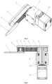
- a warehouse shuttle vehicle of this embodiment includes a vehicle body 12, a pallet fork 15 movable relative to the vehicle body 12 to extend from or retract to the vehicle body 12, and foldable shifting forks 14 mounted on the pallet fork 15.
- the pallet fork 15 includes two plate-like components arranged side by side in a horizontal direction, the two plate-like components being spaced apart and arranged oppositely to clamp goods therebetween.
- the shifting fork 14 is movable relative to the plate-like component of the pallet fork 15 to switch between a first state and a second state.
- the shifting fork 14 includes a first blocking component 2 and a second blocking component 1 connected to the first blocking component 2.
- the first blocking component 2 and the second blocking component 1 are in sequence in a direction intersecting the plate-like component of the pallet fork 15 to enable the goods to move with the movement of the pallet fork 15.
- the shifting fork 14 when the shifting fork 14 is in the second state, the first blocking component 2 and the second blocking component 1 are stacked and embedded inside the plate-like component, and the first blocking component 2 and the second blocking component 1 of the shifting fork 14 in the second state overlap in a vertical direction, thereby reducing the height of the shifting fork 14 and improving the problem that the height of a shifting fork 14 influences the storage density of a warehouse in the related art.
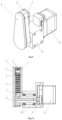
- the warehouse shuttle vehicle also includes a drive part configured to drive the shifting fork 14 to move relative to the pallet fork 15, the drive part including a support 9 mounted on the plate-like component of the shifting fork 15, a rotating shaft 8 rotatably mounted on the support 9, a first transmission wheel 7 fixedly connected to the support 9, a second transmission wheel 5 rotatably mounted to the first blocking component 2, and a flexible transmission component 6 configured to connect the first transmission wheel 7 and the second transmission wheel 5.
- the rotating shaft 8 is fixedly connected to the first blocking component 2 to cause the first blocking component 2 to rotate, so that the first blocking component 2 can rotate with the rotation of the rotating shaft 8 from a position of erecting at an inner side of the plate-like component to a position perpendicular to the plate-like component.
- the second transmission wheel 5 is in transmission cooperation with the first transmission wheel 7 and is fixedly connected to the second blocking component 1, and an axis of the second transmission wheel 5 is parallel to and spaced apart from an axis of the rotating shaft 8.
- the second transmission wheel 5 can rotate around itself and drive the second blocking component 1 to rotate relative to the first blocking component 2 while the second transmission wheel 5 rotates with the first blocking component 2 around the rotating shaft 8.
- the second blocking component 1 can also be driven by the self-rotating second transmission wheel 5 to rotate relative to the first blocking component 2 so that the second blocking component 1 rotates from a first relative position folded with the first blocking component 2 toward a second relative position side-by-side with the first blocking component 2 in the first direction described above.
- the drive part also includes a motor 11 connected to the support 9, the motor 11 being configured to cause the rotating shaft 8 to rotate.
- the motor 11 is coaxial with the rotating shaft 8.
- the support 9 is provided with a through hole that allows the rotating shaft 8 to pass through, and the rotating shaft 8 is fixed in a mounting hole of the support 9 by a first bearing 10.
- the first transmission wheel 7 is located at an end of the rotating shaft 8 away from the motor 11 and is fixedly connected to the support 9.
- the rotating shaft 8 passes through a through hole in the first transmission wheel 7 and is connected to a first end of the first blocking component 2.
- the second transmission wheel 5 is mounted to a second end of the first blocking component 2.
- a pin shaft 4 is mounted at the second end of the first blocking component 2, a second bearing 3 is sleeved on the pin shaft 4, and the second transmission wheel 5 is sleeved on the second bearing 3, with an inner ring of the second bearing 3 being connected to the pin shaft 4, and an outer ring of the second bearing 3 being connected to the second transmission wheel 5.
- An end of the second blocking component 1 is connected to the second transmission wheel 5, and the rotating shaft 8 rotates to cause the first blocking component 2 to rotate, and while rotating with the fixedly first blocking component 2, the second blocking component 1 is driven by the self-rotating second transmission wheel 5 to rotate, so as to rotate from the position stacked with the first blocking component 2 toward the position side-by-side with the first blocking component 2 in the first direction, such that the shifting fork 14 switches from the second state to the first state.
- the first transmission wheel 7 and the second transmission wheel 5 are both synchronous wheels, and the flexible transmission component 6 is a synchronous belt.
- the first transmission wheel 7 and the second transmission wheel 5 are both chain wheels, and the flexible transmission component 6 is a transmission chain.
- the first transmission wheel 7 and the second transmission wheel 5 are both gear wheels, and the first transmission wheel 7 and the second transmission wheel 5 are engaged.
- the first transmission wheel 7 and the second transmission wheel 5 are both belt pulleys, and the flexible transmission component 6 is a transmission belt.
- a gear ratio of the second transmission wheel 5 and the first transmission wheel 7 is 1:2.
- the second blocking component 1 rotates from being stacked with the first blocking component 2 to being arranged side by side with the first blocking component 2 in the direction perpendicular to the plate-like component.
- the first blocking component 2 and the second blocking component 1 of the shifting fork 14 in the second state are arranged side by side in a direction parallel to the plate-like component.
- the plate-like component is provided with a recess for receiving the shifting fork 14 in the second state, and the shifting fork 14 is located in the above-mentioned recess when it is in the second position.
- first blocking component 2 and the second blocking component 1 of the shifting fork 14 in the second state are arranged side by side in a thickness direction of the plate-like component.
- At least two shifting forks 14 are mounted on each of the two plate-like components of the pallet fork 15 of the warehouse shuttle vehicle, and the shifting forks 14 can be raised to the second state and dropped to the first state to achieve pulling out goods from a rack depository place to the shuttle vehicle or pushing goods on the shuttle vehicle into a rack depository place to fetch or store the goods.
- Each shifting fork 14 can be folded to the interior of the pallet fork 15 when raised and can be fully extended when dropped.
- a shifting fork assembly includes a second blocking component 1, a first blocking component 2, a second bearing 3, a pin shaft 4, a second transmission wheel 5, a flexible transmission component 6, a first transmission wheel 7, a rotating shaft 8, a support 9, a first bearing 10 and a motor 11, wherein the support 9 is fixedly connected to the extendable plate-like component of the pallet fork 15, the motor 11 is fixedly connected to the support 9, the first bearing 10 is mounted in an inner hole of the support 9, the first transmission wheel 7 is fixedly mounted to the support 9, the rotating shaft 8 is mounted in an inner ring of the first bearing 10, and the rotating shaft 8 is connected to an output shaft of the motor 11 and passes through an inner hole of the first transmission wheel 7 fixedly mounted to the support 9 and is fixedly connected to a first end of the first blocking component 2.
- the pin shaft 4 is fixedly connected to a second end of the first blocking component 2, the second bearing 3 is mounted to the pin shaft 4, the second transmission wheel 5 is sleeved on an outer ring of the second bearing 3, and the second transmission wheel 5 can rotate with the second bearing 3 around the pin shaft 4.
- the second blocking component 1 is fixedly connected to the second transmission wheel 5 and can rotate with the second transmission wheel 5, and the flexible transmission component 6 is wound around the second transmission wheel 5 and the first transmission wheel 7 to form a transmission pair.
- the operation of changing the shifting fork from the dropped and extended state to the raised and folded state is implanted in such a manner that the motor 11 drives, by means of the rotating shaft 8, the first blocking component 2 to rotate 90 degrees, and the second transmission wheel 5 fixedly connected to the first blocking component 2 rotates 90 degrees around an axis of the rotating shaft 8 together with the first blocking component 2; at the same time, the second transmission wheel 5 rotates around itself under the action of the transmission pair formed by the second transmission wheel 5, the flexible transmission component 6 and the first transmission wheel 7, thereby causing the second blocking component 1 fixedly connected to the second transmission wheel 5 to rotate together; as a gear ratio of the second transmission wheel 5 and the first transmission wheel 7 is set to 1:2, when the first blocking component 2 rotates 90 degrees, the second blocking component 1 rotates 180 degrees in an opposite direction, such that the second blocking component 1 overlaps with the first blocking component 2 after folded, which reduces the entire height of the shifting fork mechanism, and as they enter the interior of the pallet fork, the height of a vehicle body is not increased.
Landscapes
- Engineering & Computer Science (AREA)
- Mechanical Engineering (AREA)
- Warehouses Or Storage Devices (AREA)
Applications Claiming Priority (2)
| Application Number | Priority Date | Filing Date | Title |
|---|---|---|---|
| CN201910857686.9A CN111776559B (zh) | 2019-09-09 | 2019-09-09 | 仓库穿梭车 |
| PCT/CN2020/082701 WO2021047167A1 (zh) | 2019-09-09 | 2020-04-01 | 仓库穿梭车 |
Publications (4)
| Publication Number | Publication Date |
|---|---|
| EP4005949A1 EP4005949A1 (en) | 2022-06-01 |
| EP4005949A4 EP4005949A4 (en) | 2023-09-06 |
| EP4005949B1 true EP4005949B1 (en) | 2024-10-30 |
| EP4005949C0 EP4005949C0 (en) | 2024-10-30 |
Family
ID=72755172
Family Applications (1)
| Application Number | Title | Priority Date | Filing Date |
|---|---|---|---|
| EP20863015.2A Active EP4005949B1 (en) | 2019-09-09 | 2020-04-01 | Warehouse shuttle |
Country Status (6)
| Country | Link |
|---|---|
| US (1) | US12091249B2 (pl) |
| EP (1) | EP4005949B1 (pl) |
| JP (1) | JP7443494B2 (pl) |
| CN (1) | CN111776559B (pl) |
| PL (1) | PL4005949T3 (pl) |
| WO (1) | WO2021047167A1 (pl) |
Families Citing this family (7)
| Publication number | Priority date | Publication date | Assignee | Title |
|---|---|---|---|---|
| CN113060462B (zh) * | 2021-03-31 | 2023-04-07 | 北京京东乾石科技有限公司 | 拨叉机构及包括该拨叉机构的穿梭车 |
| USD1104856S1 (en) * | 2021-10-20 | 2025-12-09 | Intelligrated Headquarters, Llc | Shuttle car |
| JP7501496B2 (ja) | 2021-11-09 | 2024-06-18 | 株式会社ダイフク | 移載装置 |
| EP4310026A1 (de) * | 2022-07-22 | 2024-01-24 | Goya Systec S.R.L. | Transportfahrzeug für automatisierte lager |
| USD1101012S1 (en) * | 2023-02-21 | 2025-11-04 | Intelligrated Headquarters, Llc | Shuttle car |
| USD1080131S1 (en) * | 2024-03-06 | 2025-06-17 | Mecalux, S.A. | Shuttle lift system |
| US20250368439A1 (en) * | 2024-05-29 | 2025-12-04 | Intelligrated Headquarters, Llc | Wedge stop for an automated storage and retrieval system |
Citations (1)
| Publication number | Priority date | Publication date | Assignee | Title |
|---|---|---|---|---|
| CN208916747U (zh) * | 2018-08-08 | 2019-05-31 | 北京京东尚科信息技术有限公司 | 一种货叉结构和穿梭车 |
Family Cites Families (19)
| Publication number | Priority date | Publication date | Assignee | Title |
|---|---|---|---|---|
| AU5640490A (en) * | 1989-12-04 | 1991-06-26 | Caterpillar Industrial Inc. | Apparatus and method for controllably positioning forks of a material handling vehicle |
| KR101551997B1 (ko) * | 2008-10-27 | 2015-09-09 | 디마틱 어카운팅 서비시즈 게엠베하 | 자동 창고용 이동셔틀 |
| CN103068696B (zh) | 2010-08-31 | 2014-09-10 | 村田机械株式会社 | 搬送车及搬送方法 |
| CN103895999B (zh) | 2012-12-28 | 2016-04-20 | 昆山光腾智能机械有限公司 | 穿梭车 |
| JP6523296B2 (ja) | 2013-09-13 | 2019-05-29 | シムボティック エルエルシー | 自動保管および取出システム |
| JP6319011B2 (ja) * | 2014-09-19 | 2018-05-09 | 株式会社ダイフク | 物品移載装置 |
| JP6350166B2 (ja) * | 2014-09-19 | 2018-07-04 | 株式会社ダイフク | 物品搬送台車 |
| JP6398680B2 (ja) * | 2014-12-12 | 2018-10-03 | 村田機械株式会社 | サイドアーム式移載装置 |
| DE202015104093U1 (de) | 2015-08-05 | 2015-08-18 | Stickler Immobilien Gmbh | Shuttle für ein Lager |
| JP6185619B2 (ja) | 2015-10-30 | 2017-08-23 | トーヨーカネツソリューションズ株式会社 | 立体自動倉庫 |
| JP7004424B2 (ja) * | 2015-10-30 | 2022-01-21 | トーヨーカネツ株式会社 | 立体自動倉庫 |
| CN105522979A (zh) * | 2015-12-03 | 2016-04-27 | 中国航空工业集团公司洛阳电光设备研究所 | 一种组合镜用安装支架组件 |
| JP6510436B2 (ja) * | 2016-02-12 | 2019-05-08 | 株式会社日立製作所 | 物品搬送システム、搬送装置及び物品搬送方法 |
| CN208468216U (zh) * | 2017-11-10 | 2019-02-05 | 西京学院 | 一种折叠式套筒扳手横向延伸装置 |
| CN107745908A (zh) | 2017-11-30 | 2018-03-02 | 无锡凯乐士科技有限公司 | 一种新型物流穿梭车 |
| CN108147033B (zh) * | 2018-01-30 | 2023-08-15 | 合肥工业大学 | 一种具有齿轮齿条的二级伸杆穿梭车 |
| CN208802415U (zh) | 2018-08-06 | 2019-04-30 | 北京京东尚科信息技术有限公司 | 穿梭车及其拨叉机构 |
| CN108928609A (zh) * | 2018-08-31 | 2018-12-04 | 张彦晓 | 穿梭车翻爪机构及翻爪控制方法 |
| CN110203603A (zh) * | 2019-07-01 | 2019-09-06 | 无锡凯乐士科技有限公司 | 一种伸缩叉机构及穿梭车 |
-
2019
- 2019-09-09 CN CN201910857686.9A patent/CN111776559B/zh active Active
-
2020
- 2020-04-01 EP EP20863015.2A patent/EP4005949B1/en active Active
- 2020-04-01 US US17/638,413 patent/US12091249B2/en active Active
- 2020-04-01 JP JP2022513329A patent/JP7443494B2/ja active Active
- 2020-04-01 PL PL20863015.2T patent/PL4005949T3/pl unknown
- 2020-04-01 WO PCT/CN2020/082701 patent/WO2021047167A1/zh not_active Ceased
Patent Citations (1)
| Publication number | Priority date | Publication date | Assignee | Title |
|---|---|---|---|---|
| CN208916747U (zh) * | 2018-08-08 | 2019-05-31 | 北京京东尚科信息技术有限公司 | 一种货叉结构和穿梭车 |
Also Published As
| Publication number | Publication date |
|---|---|
| EP4005949A1 (en) | 2022-06-01 |
| JP2022546975A (ja) | 2022-11-10 |
| JP7443494B2 (ja) | 2024-03-05 |
| US20220324647A1 (en) | 2022-10-13 |
| CN111776559B (zh) | 2021-10-15 |
| CN111776559A (zh) | 2020-10-16 |
| EP4005949A4 (en) | 2023-09-06 |
| WO2021047167A1 (zh) | 2021-03-18 |
| EP4005949C0 (en) | 2024-10-30 |
| PL4005949T3 (pl) | 2025-01-07 |
| US12091249B2 (en) | 2024-09-17 |
Similar Documents
| Publication | Publication Date | Title |
|---|---|---|
| US12091249B2 (en) | Warehouse shuttle vehicle | |
| US12252341B2 (en) | Goods shelf shuttle and goods shelf system | |
| JP7297070B2 (ja) | 搬送車 | |
| KR20110074901A (ko) | 자동 창고용 이동셔틀 | |
| KR20200072547A (ko) | 셔틀 차량을 갖는 선반 시스템 | |
| US20240010424A1 (en) | Shuttle system for load handling in a warehouse | |
| KR20140061242A (ko) | 물품 반송 장치 및 이것을 구비한 물품 수납 설비 | |
| TWM652063U (zh) | 取貨裝置及搬運機器人 | |
| CN102910559A (zh) | 一种用于仓储物流系统的堆垛设备 | |
| CN209922136U (zh) | 一种货箱搬运机器人 | |
| KR101662955B1 (ko) | 자동화물 시스템용 이동셔틀 | |
| KR20150124059A (ko) | 스태커 크레인의 로딩장치 | |
| JP6428226B2 (ja) | サイドアーム式移載装置 | |
| KR100850881B1 (ko) | 스택커 크레인용 포크장치 | |
| CN211003000U (zh) | 货物穿梭车用上下料装置 | |
| JP5578350B2 (ja) | 物品保管設備 | |
| CN213736983U (zh) | 堆垛系统 | |
| JP5435271B2 (ja) | 物品移載装置及び物品収納設備 | |
| JP2976775B2 (ja) | 移載装置 | |
| US20260084607A1 (en) | Controlled systems for moving items in storage volume of a vehicle | |
| CN213504256U (zh) | 一种超长超高超重货物的自动存取装置 | |
| CN112830069B (zh) | 一种可稳定堆垛的货物多式联运用转运装置 | |
| CN220997890U (zh) | 自动化仓储移动立体库 | |
| CN118545415B (zh) | 用于无人舰船的火工品仓储系统 | |
| CN218786389U (zh) | 一种龙门装车机 |
Legal Events
| Date | Code | Title | Description |
|---|---|---|---|
| STAA | Information on the status of an ep patent application or granted ep patent |
Free format text: STATUS: THE INTERNATIONAL PUBLICATION HAS BEEN MADE |
|
| PUAI | Public reference made under article 153(3) epc to a published international application that has entered the european phase |
Free format text: ORIGINAL CODE: 0009012 |
|
| STAA | Information on the status of an ep patent application or granted ep patent |
Free format text: STATUS: REQUEST FOR EXAMINATION WAS MADE |
|
| 17P | Request for examination filed |
Effective date: 20220225 |
|
| AK | Designated contracting states |
Kind code of ref document: A1 Designated state(s): AL AT BE BG CH CY CZ DE DK EE ES FI FR GB GR HR HU IE IS IT LI LT LU LV MC MK MT NL NO PL PT RO RS SE SI SK SM TR |
|
| DAV | Request for validation of the european patent (deleted) | ||
| DAX | Request for extension of the european patent (deleted) | ||
| A4 | Supplementary search report drawn up and despatched |
Effective date: 20230804 |
|
| RIC1 | Information provided on ipc code assigned before grant |
Ipc: B65G 1/04 20060101AFI20230731BHEP |
|
| GRAP | Despatch of communication of intention to grant a patent |
Free format text: ORIGINAL CODE: EPIDOSNIGR1 |
|
| STAA | Information on the status of an ep patent application or granted ep patent |
Free format text: STATUS: GRANT OF PATENT IS INTENDED |
|
| INTG | Intention to grant announced |
Effective date: 20240610 |
|
| GRAS | Grant fee paid |
Free format text: ORIGINAL CODE: EPIDOSNIGR3 |
|
| GRAA | (expected) grant |
Free format text: ORIGINAL CODE: 0009210 |
|
| STAA | Information on the status of an ep patent application or granted ep patent |
Free format text: STATUS: THE PATENT HAS BEEN GRANTED |
|
| AK | Designated contracting states |
Kind code of ref document: B1 Designated state(s): AL AT BE BG CH CY CZ DE DK EE ES FI FR GB GR HR HU IE IS IT LI LT LU LV MC MK MT NL NO PL PT RO RS SE SI SK SM TR |
|
| REG | Reference to a national code |
Ref country code: GB Ref legal event code: FG4D |
|
| REG | Reference to a national code |
Ref country code: CH Ref legal event code: EP |
|
| REG | Reference to a national code |
Ref country code: DE Ref legal event code: R096 Ref document number: 602020040513 Country of ref document: DE |
|
| REG | Reference to a national code |
Ref country code: IE Ref legal event code: FG4D |
|
| U01 | Request for unitary effect filed |
Effective date: 20241030 |
|
| U07 | Unitary effect registered |
Designated state(s): AT BE BG DE DK EE FI FR IT LT LU LV MT NL PT RO SE SI Effective date: 20241106 |
|
| PG25 | Lapsed in a contracting state [announced via postgrant information from national office to epo] |
Ref country code: IS Free format text: LAPSE BECAUSE OF FAILURE TO SUBMIT A TRANSLATION OF THE DESCRIPTION OR TO PAY THE FEE WITHIN THE PRESCRIBED TIME-LIMIT Effective date: 20250228 Ref country code: HR Free format text: LAPSE BECAUSE OF FAILURE TO SUBMIT A TRANSLATION OF THE DESCRIPTION OR TO PAY THE FEE WITHIN THE PRESCRIBED TIME-LIMIT Effective date: 20241030 |
|
| PG25 | Lapsed in a contracting state [announced via postgrant information from national office to epo] |
Ref country code: ES Free format text: LAPSE BECAUSE OF FAILURE TO SUBMIT A TRANSLATION OF THE DESCRIPTION OR TO PAY THE FEE WITHIN THE PRESCRIBED TIME-LIMIT Effective date: 20241030 |
|
| PG25 | Lapsed in a contracting state [announced via postgrant information from national office to epo] |
Ref country code: NO Free format text: LAPSE BECAUSE OF FAILURE TO SUBMIT A TRANSLATION OF THE DESCRIPTION OR TO PAY THE FEE WITHIN THE PRESCRIBED TIME-LIMIT Effective date: 20250130 |
|
| PG25 | Lapsed in a contracting state [announced via postgrant information from national office to epo] |
Ref country code: GR Free format text: LAPSE BECAUSE OF FAILURE TO SUBMIT A TRANSLATION OF THE DESCRIPTION OR TO PAY THE FEE WITHIN THE PRESCRIBED TIME-LIMIT Effective date: 20250131 |
|
| PG25 | Lapsed in a contracting state [announced via postgrant information from national office to epo] |
Ref country code: RS Free format text: LAPSE BECAUSE OF FAILURE TO SUBMIT A TRANSLATION OF THE DESCRIPTION OR TO PAY THE FEE WITHIN THE PRESCRIBED TIME-LIMIT Effective date: 20250130 |
|
| U20 | Renewal fee for the european patent with unitary effect paid |
Year of fee payment: 6 Effective date: 20250321 |
|
| PG25 | Lapsed in a contracting state [announced via postgrant information from national office to epo] |
Ref country code: SM Free format text: LAPSE BECAUSE OF FAILURE TO SUBMIT A TRANSLATION OF THE DESCRIPTION OR TO PAY THE FEE WITHIN THE PRESCRIBED TIME-LIMIT Effective date: 20241030 |
|
| PG25 | Lapsed in a contracting state [announced via postgrant information from national office to epo] |
Ref country code: SK Free format text: LAPSE BECAUSE OF FAILURE TO SUBMIT A TRANSLATION OF THE DESCRIPTION OR TO PAY THE FEE WITHIN THE PRESCRIBED TIME-LIMIT Effective date: 20241030 |
|
| PG25 | Lapsed in a contracting state [announced via postgrant information from national office to epo] |
Ref country code: CZ Free format text: LAPSE BECAUSE OF FAILURE TO SUBMIT A TRANSLATION OF THE DESCRIPTION OR TO PAY THE FEE WITHIN THE PRESCRIBED TIME-LIMIT Effective date: 20241030 |
|
| PLBE | No opposition filed within time limit |
Free format text: ORIGINAL CODE: 0009261 |
|
| STAA | Information on the status of an ep patent application or granted ep patent |
Free format text: STATUS: NO OPPOSITION FILED WITHIN TIME LIMIT |
|
| 26N | No opposition filed |
Effective date: 20250731 |
|
| REG | Reference to a national code |
Ref country code: CH Ref legal event code: H13 Free format text: ST27 STATUS EVENT CODE: U-0-0-H10-H13 (AS PROVIDED BY THE NATIONAL OFFICE) Effective date: 20251125 |
|
| PG25 | Lapsed in a contracting state [announced via postgrant information from national office to epo] |
Ref country code: MC Free format text: LAPSE BECAUSE OF FAILURE TO SUBMIT A TRANSLATION OF THE DESCRIPTION OR TO PAY THE FEE WITHIN THE PRESCRIBED TIME-LIMIT Effective date: 20241030 |
|
| GBPC | Gb: european patent ceased through non-payment of renewal fee |
Effective date: 20250401 |
|
| PG25 | Lapsed in a contracting state [announced via postgrant information from national office to epo] |
Ref country code: GB Free format text: LAPSE BECAUSE OF NON-PAYMENT OF DUE FEES Effective date: 20250401 |
|
| PG25 | Lapsed in a contracting state [announced via postgrant information from national office to epo] |
Ref country code: CH Free format text: LAPSE BECAUSE OF NON-PAYMENT OF DUE FEES Effective date: 20250430 |
|
| PG25 | Lapsed in a contracting state [announced via postgrant information from national office to epo] |
Ref country code: IE Free format text: LAPSE BECAUSE OF NON-PAYMENT OF DUE FEES Effective date: 20250401 |
|
| U20 | Renewal fee for the european patent with unitary effect paid |
Year of fee payment: 7 Effective date: 20260317 |
|
| PGFP | Annual fee paid to national office [announced via postgrant information from national office to epo] |
Ref country code: PL Payment date: 20260319 Year of fee payment: 7 |