EP4005965A1 - Dispositif d'extension de flèche pour grue à conteneurs de port, et son procédé d'extension - Google Patents
Dispositif d'extension de flèche pour grue à conteneurs de port, et son procédé d'extension Download PDFInfo
- Publication number
- EP4005965A1 EP4005965A1 EP19943755.9A EP19943755A EP4005965A1 EP 4005965 A1 EP4005965 A1 EP 4005965A1 EP 19943755 A EP19943755 A EP 19943755A EP 4005965 A1 EP4005965 A1 EP 4005965A1
- Authority
- EP
- European Patent Office
- Prior art keywords
- boom
- extension
- section
- trolley
- container crane
- Prior art date
- Legal status (The legal status is an assumption and is not a legal conclusion. Google has not performed a legal analysis and makes no representation as to the accuracy of the status listed.)
- Pending
Links
Images


Classifications
-
- B—PERFORMING OPERATIONS; TRANSPORTING
- B66—HOISTING; LIFTING; HAULING
- B66C—CRANES; LOAD-ENGAGING ELEMENTS OR DEVICES FOR CRANES, CAPSTANS, WINCHES, OR TACKLES
- B66C11/00—Trolleys or crabs, e.g. operating above runways
- B66C11/14—Trolleys or crabs, e.g. operating above runways adapted to operate on crane or bridge structure of particular configuration, e.g. on reinforced concrete girders of rectangular cross-section
-
- B—PERFORMING OPERATIONS; TRANSPORTING
- B66—HOISTING; LIFTING; HAULING
- B66C—CRANES; LOAD-ENGAGING ELEMENTS OR DEVICES FOR CRANES, CAPSTANS, WINCHES, OR TACKLES
- B66C6/00—Girders, or track-supporting structures, specially adapted for cranes
-
- B—PERFORMING OPERATIONS; TRANSPORTING
- B66—HOISTING; LIFTING; HAULING
- B66C—CRANES; LOAD-ENGAGING ELEMENTS OR DEVICES FOR CRANES, CAPSTANS, WINCHES, OR TACKLES
- B66C13/00—Other constructional features or details
- B66C13/04—Auxiliary devices for controlling movements of suspended loads, or preventing cable slack
- B66C13/08—Auxiliary devices for controlling movements of suspended loads, or preventing cable slack for depositing loads in desired attitudes or positions
-
- B—PERFORMING OPERATIONS; TRANSPORTING
- B66—HOISTING; LIFTING; HAULING
- B66C—CRANES; LOAD-ENGAGING ELEMENTS OR DEVICES FOR CRANES, CAPSTANS, WINCHES, OR TACKLES
- B66C19/00—Cranes comprising trolleys or crabs running on fixed or movable bridges or gantries
- B66C19/002—Container cranes
Definitions
- the present invention relates to a boom of a crane, and in particular to a boom extension device for a dockside container crane, and an extension method for same.
- the commonly used boom extension solutions mainly include: 1. the front boom is put to the ground by a floating crane for extension; and 2. the quay crane is pulled to the back, and the front boom is put downwards by large lifting equipment (truck crane or crawler crane) and is reset after extension.
- the two solutions have high requirements on the lifting equipment and sites, and have long construction period and high cost.
- the problem to be solved by the present invention is how to reduce the use of large equipment.
- the present invention provides a boom extension device for a dockside container crane, and an extension method for same, thereby reducing the use of large equipment.
- a boom includes a rear boom section and a front boom section.
- the extension device includes: an extension trolley tool, used to be arranged below the rear boom section and the front boom section during extension operation and including a wheel set, a trolley frame, a construction platform, and a movement track arranged on the construction platform; a first support frame trolley, arranged on the movement track and used to carry a boom extension section and guide the boom extension section to move in a first direction; and a second support frame trolley, arranged on the movement track and used to carry the front boom section and guide the front boom section to move in a second direction perpendicular to the first direction in a first plane.
- the embodiment of the present invention discloses a boom extension device for a dockside container crane, including: a process support, mounted on two sides of a cutting line.
- boom bodies at two ends can be prevented from shrinkage or expansion deformation after the boom is cut.
- the embodiment of the present invention discloses a boom extension device for a dockside container crane, wherein a process support includes a first process support and a second process support, two ends of the first process support are connected to two inner side walls of the rear boom section, and two ends of the second process support are connected to two inner side walls of the front boom section.
- the boom is cut into the front boom section and the rear boom section along the cutting line, the two ends of the first process support are connected to the two inner side walls of the rear boom section, and the two ends of the second process support are connected to the two inner side walls of the front boom section, so that the front boom section and the rear boom section can be prevented from shrinkage or expansion deformation.
- the embodiment of the present invention discloses a boom extension device for a dockside container crane, wherein a boom extension section is arranged below the second process support.
- the boom extension section may directly move in a first direction to be aligned with the rear boom section, thereby preventing the boom extension section from being singly lifted from the ground to high altitude, and reducing the use of large equipment.
- the embodiment of the present invention discloses a boom extension device for a dockside container crane, further including: jacks, arranged below the front boom section and the boom extension section.
- the jacks arranged below the front boom section and the boom extension section may adjust the heights of the front boom section and the boom extension section.
- an embodiment of the present invention discloses a boom extension device for a dockside container crane, wherein the extension trolley tool further includes: detachable casing handrails, arranged on casings around the trolley frame.
- the detachable casing handrails are provided, thereby facilitating disassembly, assembly and transportation, and further ensuring the safety of workers in the operation process.
- the embodiment of the present invention discloses a boom extension device for a dockside container crane, wherein a distance between the first process support or/and the second process support and the cutting line is 800 mm.
- selecting the arrangement position of the first process support or/and the second process support can effectively prevent the front boom section and the rear boom section from shrinkage or expansion deformation.
- the embodiment of the present invention discloses a boom extension device for a dockside container crane, wherein the process support is a round pipe.
- the round pipe has high rigidity and strength, and the round pipe, as the process support, can effectively prevent the front boom section and the rear boom section from shrinkage or expansion deformation.
- the embodiment of the present invention discloses a boom extension device for a dockside container crane, further including a stop plate, arranged on a head part of the extension trolley tool.
- the second support frame trolley can be effectively prevented from separation when carrying the front boom section and guiding the front boom section to move in a second direction perpendicular to the first direction in a first plane to a limiting position, thereby avoiding potential safety hazards.
- the embodiment of the present invention disclose a boom extension device for a dockside container crane, further including crossties, arranged on the first support frame trolley and the second support frame trolley.
- the crossties and the jacks are used to adjust the height of the boom extension section.
- the embodiment of the present invention discloses a boom extension device for a dockside container crane, further including: pull lugs and steel wire ropes, which are arranged in the second direction and are used to move the front boom section.
- the front boom section is moved in the second direction through chain blocks and the pull lugs.
- An embodiment of the present invention further discloses an extension method for a boom of a dockside container crane, including: arranging an extension trolley tool below a boom; cutting the boom along a cutting line to form a rear boom section and a front boom section; moving the front boom section in place in a second direction and fixing the front boom section; moving a boom extension section to be between the rear boom section and the front boom section and performing mutual alignment; and connecting the boom extension section to the rear boom section and the front boom section.
- the embodiment of the present invention discloses an extension method for a boom of a dockside container crane. Before the step of arranging the extension trolley tool below the boom, the method includes: assembling a trolley frame of the extension trolley tool on the ground, and mounting a construction platform.
- the trolley frame of the extension trolley tool is assembled on the ground and the construction platform is mounted, so that the aloft workload is reduced.
- the embodiment of the present invention discloses an extension method for a boom of a dockside container crane. After the step of assembling the trolley frame of the extension trolley tool on the ground and mounting the construction platform, the method includes: lifting the trolley frame, and performing aerial docking on the trolley frame and a wheel set lifted on the boom to complete assembly of the extension trolley tool, wherein the extension trolley tool includes the wheel set, the trolley frame, the construction platform, and a movement track arranged on the construction platform.
- the embodiment of the present invention discloses an extension method for a boom of a dockside container crane. Before the step of cutting the boom along the cutting line to form the rear boom section and the front boom section, the method includes: arranging a process support on two sides of the cutting line in a first direction.
- boom bodies at two ends can be prevented from shrinkage or expansion deformation after the boom is cut.
- the embodiment of the present invention discloses an extension method for a boom of a dockside container crane.
- the step of moving the front boom section in place in the second direction and fixing the front boom section includes: arranging pull lugs and steel wire ropes in the second direction for moving the front boom section arranged on a second support frame trolley.
- the front boom section is moved in the second direction through chain blocks and the pull lugs.
- the embodiment of the present invention discloses an extension method for a boom of a dockside container crane.
- the step of moving the front boom section in place in the second direction and fixing the front boom section includes: locking the chain blocks and wheels of the second support frame trolley after the front boom section is in place.
- the embodiment of the present invention discloses an extension method for a boom of a dockside container crane.
- the step of moving the front boom section in place in the second direction and fixing the front boom section includes: arranging a stop plate on a head part of the extension trolley tool so as to prevent the second support frame trolley from separation after arriving at a limiting position.
- the second support frame trolley can be effectively prevented from separation when carrying the front boom section and guiding the front boom section to move in the second direction perpendicular to the first direction in a first plane to a limiting position, thereby avoiding potential safety hazards.
- the embodiment of the present invention discloses an extension method for a boom of a dockside container crane.
- the step of moving the boom extension section to be between the rear boom section and the front boom section and performing mutual alignment includes: moving the boom extension section arranged on the first support frame trolley in the first direction to be between the rear boom section and the front boom section; and moving the boom extension section in a third direction and performing mutual alignment on the boom extension section and the rear boom section in the second direction.
- the boom extension section is slightly lower than the rear boom section before the boom extension section is moved, then the height of the boom extension section in the third direction is adjusted by jacks and crossties, which are placed on the second support frame trolley, the boom extension section is docked with the rear boom section firstly based on the rear boom section because the rear boom section is entirely stable and the precision is higher after docking, subsequently, it is also necessary to perform micro-adjustment on the front boom section, and the height of the boom extension section in the third direction is adjusted through the jacks after the boom extension section moves in place in the first direction.
- the embodiment of the present invention discloses an extension method for a boom of a dockside container crane. After the step of completing the assembly of the extension trolley tool, the method includes: moving the extension trolley tool to be below the front boom section by moving a bridge crane trolley.
- the extension trolley tool is moved to be below the front boom section by moving the bridge crane trolley, and then the extension trolley tool is fixed to be integrated with the boom.
- the embodiment of the present invention discloses an extension method for a boom of a dockside container crane. After the step of completing the assembly of the extension trolley tool, the method includes: lifting the first support frame trolley, the second support frame trolley, the process support and the boom extension section to the trolley frame and performing fixation.
- the first support frame trolley, the second support frame trolley, the process support and the boom extension section are lifted to the trolley frame by using a truck crane and are fixed, thereby preventing the extension trolley tool from slipping after moving.
- the embodiment of the present invention discloses an extension method for a boom of a dockside container crane. After the step of moving the extension trolley tool to be below the front boom section, the method includes: disconnecting the bridge crane trolley and the extension trolley tool.
- connection rod between the bridge crane trolley and the extension trolley tool is removed, the bridge crane trolley runs to a parking space, stops and anchors, and then the steel wire ropes for pulling the trolley are removed.
- the embodiment of the present invention discloses an extension method for a boom of a dockside container crane. Before the step of connecting the boom extension section to the rear boom section and the front boom section, the method includes: controlling the docking flatness of a port and welding shrinkage of a splicing seam.
- the boom bodies at the two ends and the boom extension section can be further prevented from shrinkage or expansion deformation.
- orientations or position relationships indicated by terms “upper”, “lower”, “inner”, “bottom” and the like are orientation or position relationships shown in the accompanying drawings, or are orientation or position relationships that the product of the present invention is usually placed during use, and these terms are only used to facilitate description of the present invention and simplify the description, but not to indicate or imply that the mentioned apparatus or components must have a specific orientation or must be established and operated in a specific orientation, and thus these terms cannot be understood as a limitation to the present invention.
- First plane in the present invention refers to a plane where a first direction is perpendicular to a second direction.
- a first plane includes a first direction A and a second direction B, wherein the second direction B may be regarded as an axial direction of a boom, and the first direction A may be regarded as a direction perpendicular to the axial direction of the boom in the first plane.
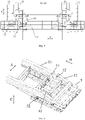
- FIG. 1 is a structural schematic diagram of a boom extension device for a dockside container crane according to an embodiment of the present invention.
- FIG. 2 is a first structural schematic diagram of an extension trolley tool of a boom extension device for a dockside container crane according to an embodiment of the present invention.
- FIG. 3 is a second structural schematic diagram of an extension trolley tool of a boom extension device for a dockside container crane according to an embodiment of the present invention.
- the boom includes a rear boom section 11 and a front boom section 12.
- the extension device includes: an extension trolley tool 2, used to be arranged below the rear boom section 11 and the front boom section 12 during extension operation and including a wheel set 21, a trolley frame 22, a construction platform 23, and a movement track 24 arranged on the construction platform 23; a first support frame trolley 31, arranged on the movement track 24 and used to carry a boom extension section 41 and guide the boom extension section 41 to move in a first direction A; and a second support frame trolley 32, arranged on the movement track 24 and used to carry the front boom section 12 and guide the front boom section 12 to move in a second direction B perpendicular to the first direction A in a first plane.
- an extension trolley tool 2 used to be arranged below the rear boom section 11 and the front boom section 12 during extension operation and including a wheel set 21, a trolley frame 22, a construction platform 23, and a movement track 24 arranged on the construction platform 23
- the extension trolley tool 2 is arranged below the rear boom section 11 and the front boom section 12, the first support frame trolley 31 carries the boom extension device 41 to be arranged on the movement track 24, and the second support frame trolley 32 is arranged on the movement track 24 and is used to carry the front boom section to move in the second direction B perpendicular to the first direction A in the first plane during extension operation.
- the boom extension device for the dockside container crane provided by the embodiment of the present invention is safe and reliable, and can extend the boom after being mounted in place, it is unnecessary to mount auxiliary equipment, a quay crane does not need to move, and extension operation can be performed on the original operation track, so that the use of large equipment is reduced.
- FIG. 1 is a structural schematic diagram of a boom extension device for a dockside container crane according to an embodiment of the present invention.
- FIG. 4 is a first schematic diagram of extension operation of a boom extension device for a dockside container crane according to an embodiment of the present invention.
- the technical solution of the embodiment is basically the same as the solution in the embodiment 1, except that a process support 5 arranged on two sides of a cutting line L is further included in the embodiment. Specifically, before the boom is cut, the process support 5 is mounted on two sides of the cutting line L, so that boom bodies at two ends, i.e., the front boom section 12 and the rear boom section 11, can be prevented from shrinkage or expansion deformation after the boom is cut.
- FIG. 1 is a structural schematic diagram of a boom extension device for a dockside container crane according to an embodiment of the present invention.
- FIG. 4 is a first schematic diagram of extension operation of a boom extension device for a dockside container crane according to an embodiment of the present invention.
- the technical solution of the embodiment is basically the same as the solution in the embodiment 1, except that the embodiment further includes that the process support 5 includes a first process support 51 and a second process support 52, wherein two ends of the first process support 51 are connected to two inner side walls of the rear boom section 11, and two ends of the second process support 52 are connected to two inner side walls of the front boom section 12.
- the first process support 51 and the second process 52 are mounted on two sides of the cutting line L respectively, two ends of the first process support 51 are connected to inner side walls of the boom, and two ends of the second process support 52 are connected to the inner side walls of the boom.
- connection positions of the first process support 51 may be regarded as that the two ends of the first process support 51 are connected to two inner side walls of the rear boom section 11, and the connection positions of the second process support 52 may be regarded as that the two ends of the second process support 52 are connected to two inner side walls of the front boom section 12, so that the cutting port of the front boom section 12 and the rear boom section 11 is prevented from shrinkage and expansion deformation.
- FIG. 9 is a fourth schematic diagram of extension operation of a boom extension device for a dockside container crane according to an embodiment of the present invention.
- the technical solution of the embodiment is basically the same as the solution in the embodiment 1, except that a boom extension section 41 arranged below the second process support 52 is further included in the embodiment. Specifically, before extension operation, the boom extension section 41 is arranged below the second process support 52. During extension operation, after the front boom section 12 provided with the second process support 52 moves in place, the boom extension section 41 may directly move in the first direction A and is aligned with the rear boom section 11.
- the ingenious structural design prevents the boom extension section 41 from being singly lifted from the ground to high altitude, the use of large equipment is further reduced, and the efficiency of the extension operation is improved.
- FIG. 1 is a structural schematic diagram of a boom extension device for a dockside container crane according to an embodiment of the present invention.
- the technical solution of the embodiment is basically the same as the solution in the embodiment 1, except that jacks 6 arranged below the front boom section 12 and the rear boom section 11 are further included in the embodiment.
- the jacks 6 arranged below the front boom section 12 and the rear boom section 11 may adjust the position heights of the front boom section 12 and the rear boom section 11 in a third direction C.
- FIG. 1 is a structural schematic diagram of a boom extension device for a dockside container crane according to an embodiment of the present invention.
- FIG. 3 is a second structural schematic diagram of an extension trolley tool of a boom extension device for a dockside container crane according to an embodiment of the present invention.
- the technical solution of the embodiment is basically the same as the solution in the embodiment 1, except that an extension trolley tool is further included in the embodiment, wherein the extension trolley tool further includes: detachable casing handrails 7 arranged on casings around the trolley frame 22. Specifically, the detachable casing handrails 7 are provided, thereby facilitating disassembly, assembly and transportation, and further ensuring the safety of workers in the operation process.
- FIG. 1 is a structural schematic diagram of a boom extension device for a dockside container crane according to an embodiment of the present invention.
- FIG. 4 is a first schematic diagram of extension operation of a boom extension device for a dockside container crane according to an embodiment of the present invention.
- the technical solution of the embodiment is basically the same as the solution in the embodiment 1, except that the embodiment further includes that a distance between the first process support or/and the second process support and the cutting line is 800 mm.
- the distance between the first process support 51 or/and the second process support 52 and the cutting line L is preferably 800 mm, so that the cutting port of the front boom section 12 and the rear boom section 11 can be effectively prevented from shrinkage and expansion deformation.
- FIG. 1 is a structural schematic diagram of a boom extension device for a dockside container crane according to an embodiment of the present invention.
- the technical solution of the embodiment is basically the same as the solution in the embodiment 1, except that the embodiment further includes that the process support is a round pipe, the round pipe has high rigidity and strength, and the round pipe, as the process support, can effectively prevent the front boom section and the rear boom section from shrinkage or expansion deformation.
- the description of the process support according to the embodiment of the present invention is not limited therewith.
- FIG. 1 is a structural schematic diagram of a boom extension device for a dockside container crane according to an embodiment of the present invention.
- FIG. 4 is a first schematic diagram of extension operation of a boom extension device for a dockside container crane according to an embodiment of the present invention.
- the technical solution of the embodiment is basically the same as the solution in the embodiment 1, except that a stop plate 8 arranged on a head part of the extension trolley tool 2 is further included in the embodiment, so that the second support frame trolley 32 can be effectively prevented from separation when carrying the front boom section 12 and guiding the front boom section 12 to move in the second direction B perpendicular to the first direction A in the first plane to a limiting position, thereby avoiding potential safety hazards.
- FIG. 4 is a first schematic diagram of extension operation of a boom extension device for a dockside container crane according to an embodiment of the present invention.
- the technical solution of the embodiment is basically the same as the solution in the embodiment 1, except that crossties 9 arranged on the first support frame trolley 31 and the second support frame trolley 32 are further included in the embodiment.
- the crosstie 9 may be arranged between the jack 6 and the second support frame trolley 32, or may be directly arranged between the front boom section 12 and the second support frame trolley 32, and may effectively adjust the position height of the boom extension section 41 in the third direction C.
- the crosstie 9 on the first support frame trolley 31 may have the same arrangement mode as that on the second support frame trolley 32, or the crossties 9 may be arranged on the first support frame trolley 31 according to FIG. 6 , but the present invention is not limited therewith.
- FIG. 5 is a second schematic diagram of extension operation of a boom extension device for a dockside container crane according to an embodiment of the present invention.
- FIG. 8 is a schematic diagram of FIG. 1 in an S1 direction.
- the technical solution of the embodiment is basically the same as the solution in the embodiment 1, except that the embodiment further includes pull lugs 10 and steel wire ropes which are arranged in the second direction B and are used to move the front boom section 12, and the front boom section 12 is moved by chain blocks 11 and the pull lugs 10 along the second direction B (referring to the second direction B in FIG. 5 ).
- FIG. 7 is a flowchart of an extension method for a boom of a dockside container crane according to an embodiment of the present invention.
- FIG. 7 is a flowchart of an extension method for a boom of a dockside container crane according to an embodiment of the present invention.
- the extension device for the boom of the dockside container crane according to the specific embodiment of the present invention includes:
- FIG. 4 is a first schematic diagram of extension operation of a boom extension device for a dockside container crane according to an embodiment of the present invention.
- an extension trolley tool 2 is arranged below the boom; during extension operation, the boom is cut along a cutting line L to form a rear boom section 11 and a front boom section 12; according to the requirements of the extension operation, the front boom section 12 is moved in place in a second direction B and is fixed, and the moving distance of the front boom section 12 in the second direction B is slightly greater than the length of a boom extension section 41, thereby facilitating adjustment of the position of the boom extension section 41 and effective implementation of the extension operation; the boom extension section 41 is moved to be between the rear boom section 11 and the front boom section 12 and mutual alignment is performed; and the boom extension section 41 is connected to the rear boom section 11 and the front boom section 12, wherein the connection may be welding.
- the extension method for the boom of the dockside container crane provided by the embodiment of the present invention is safe and reliable, it is unnecessary to mount auxiliary equipment, a quay crane does not need to move, and the extension operation can be performed on an original operation track, so that the use of large equipment is reduced.
- FIG. 2 is a first structural schematic diagram of an extension trolley tool of a boom extension device for a dockside container crane according to an embodiment of the present invention.
- FIG. 3 is a second structural schematic diagram of an extension trolley tool of a boom extension device for a dockside container crane according to an embodiment of the present invention.
- the technical solution of the embodiment is basically the same as the solution in the embodiment 2, except that the embodiment further includes that before the step that the extension trolley tool 2 is arranged below the boom, the method includes: a trolley frame 22 of the extension trolley tool 2 is assembled on the ground, and a construction platform 23 is mounted. Specifically, the trolley frame 22 of the extension trolley tool 2 is assembled on the ground and the construction platform 23 is mounted, so that the aloft workload is reduced and higher safety is achieved.
- FIG. 2 is a first structural schematic diagram of an extension trolley tool of a boom extension device for a dockside container crane according to an embodiment of the present invention.
- FIG. 3 is a second structural schematic diagram of an extension trolley tool of a boom extension device for a dockside container crane according to an embodiment of the present invention.
- the technical solution of the embodiment is basically the same as the solution in the embodiment 2, except that the embodiment further includes that after the step that the trolley frame 22 of the extension trolley tool 2 is assembled on the ground and the construction platform 23 is mounted, the method includes: the trolley frame 22 is lifted to be subjected to areal docking with a wheel set 21 lifted on the boom to complete assembly of the extension trolley tool 2, wherein the extension trolley tool 2 includes the wheel set 21, the trolley frame 22, the construction platform 23, and a movement track 24 arranged on the construction platform 23.
- the wheel set 21 (which may be three wheel sets) is firstly lifted by a truck crane to the boom above the movement track 24, then the trolley frame 22 is lifted by a winch to be subjected to aerial docking with the wheel set 21 on the boom, and flanges on the trolley frame 22 and the wheel set 21 are adjusted by chain blocks until bolts are assembled completely, thereby completing assembly of the extension trolley tool 2.
- the assembly of the whole extension trolley tool has small aloft workload and higher safety, and the stability of the extension trolley tool is higher.
- FIG. 1 is a structural schematic diagram of a boom extension device for a dockside container crane according to an embodiment of the present invention.
- FIG. 4 is a first schematic diagram of extension operation of a boom extension device for a dockside container crane according to an embodiment of the present invention.
- the technical solution of the embodiment is basically the same as the solution in the embodiment 2, except that the embodiment further includes that before the step that the boom is cut along the cutting line L to form the rear boom section 11 and the front boom section 12, the method includes: a process support 5 is arranged on two sides of the cutting line L in the first direction A. Boom bodies at two ends, i.e., the front boom section 12 and the rear boom section 11, are prevented from shrinkage or expansion deformation after the boom is cut.
- the technical solution of the embodiment is basically the same as the solution in the embodiment 2, except that the embodiment further includes that the front boom section 12 is moved in place in the second direction B and is fixed includes: pull lugs and steel wire ropes are arranged in the second direction B for moving the front boom section 12 arranged on a second support frame trolley 32. Specifically, the pull lugs and the steel wire ropes are arranged in the second direction B for moving the front boom section 12, and the front boom section 12 is moved by the chain blocks and the pull lugs in the second direction B.
- the technical solution of the embodiment is basically the same as the solution in the embodiment 2, except that the embodiment further includes that the step that the front boom section 12 is moved in place in the second direction B and is fixed includes: after the front boom section 12 is in place, the chain blocks and wheels of the second support frame trolley 32 are locked, thereby avoiding potential safety hazards caused by the sliding of the front boom section 12.
- FIG. 5 is a second schematic diagram of extension operation of a boom extension device for a dockside container crane according to an embodiment of the present invention.
- the technical solution of the embodiment is basically the same as the solution in the embodiment 2, except that the embodiment further includes that the step that the front boom section 12 is moved in place in the second direction B and is fixed includes: a stop plate 8 is arranged on a head part of the extension trolley tool 2 to prevent the second support frame trolley 32 from separation after arriving at a limiting position.
- FIG. 6 is a third schematic diagram of extension operation of a boom extension device for a dockside container crane according to an embodiment of the present invention.
- the technical solution of the embodiment is basically the same as the solution in the embodiment 2, except that the embodiment further includes that the step that the boom extension section 41 is moved to be between the rear boom section 11 and the front boom section 12 and mutual alignment is performed includes: the boom extension section 41 arranged on a first support frame trolley 31 is moved to be between the rear boom section 11 and the front boom section 12 in the first direction A; and the boom extension section 41 is moved in a third direction C, and mutual alignment is performed on the boom extension section 41 and the rear boom section 11 in the second direction B.
- the height of the boom extension section 41 in the third direction C is adjusted by jacks 6 and crossties which are placed on the second support frame trolley 32, the boom extension section 41 is docked with the rear boom section 11 firstly based on the rear boom section 11 because the rear boom section 11 is entirely stable and the precision is higher after docking, subsequently, it is also necessary to perform micro-adjustment on the front boom section 12 subsequently, and the height of the boom extension section 41 in the third direction C is adjusted through the jacks 6 after the boom extension section 41 moves in place in the first direction.
- the technical solution of the embodiment is basically the same as the solution in the embodiment 2, except that the embodiment further includes that after the step that assembly of the extension trolley tool 2 is completed, the method includes: the extension trolley tool 2 is moved to be below the front boom section 12 by moving a bridge crane trolley, and then the extension trolley tool 2 is fixed to be integrated with the boom.
- the technical solution of the embodiment is basically the same as the solution in the embodiment 2, except that that embodiment further includes that after the step that assembly of the extension trolley tool 2 is completed, the method includes: the first support frame trolley 31, the second support frame trolley 32, the process support 5 and the boom extension section 41 are lifted to the trolley frame 22 and are fixed. Specifically, the first support frame trolley 31, the second support frame trolley 32, the process support 5 and the boom extension section 41 are lifted to the trolley frame 22 by a truck crane and are fixed, thereby preventing the extension trolley tool from slipping after moving.
- the technical solution of the embodiment is basically the same as the solution in the embodiment 2, except that the embodiment further includes that after the step that the extension trolley tool 2 is moved to be below the front boom section 12, the method includes: the bridge crane trolley and the extension trolley tool 2 are disconnected. Specifically, a connection rod between the bridge crane trolley and the extension trolley tool is removed, the bridge crane trolley runs to a parking space, stops and anchors, and then the steel wire ropes for pulling the trolley are removed.
- the technical solution of the embodiment is basically the same as the solution in the embodiment 2, except that the embodiment further includes that before the step that the boom extension section 41 is connected to the rear boom section 11 and the front boom section 12, the method includes: the docking flatness of a port and welding shrinkage of a splicing seam are controlled. Specifically, before the boom extension section 41 is connected to the rear boom section 11 and the front boom section 12, wherein the connection may be welding, the port splicing position is fixed through a fixture, so that the docking flatness of the port and welding shrinkage of the splicing seam are controlled.
- spot welding is performed to complete the docking of the boom extension section and the rear boom section; then the docking of the front boom section and the boom extension section is completed according to the above step, and welding starts to be performed after all the spot welding work is completed, after welding, the quality of the welding seam is checked, and subsequent work such as polishing and painting is performed; a tool piece is disassembled, and connection of the steel wire ropes and the accessories is restored; and functions, mainly referring to speed-reducing limitation on the boom, displacement of parking limitation space, extension of an anti-collision system, or the like, required by extension operation, are subjected to restoration or extended restoration.
- the present invention may include combinations of various specific embodiments described below.
- a boom includes a rear boom section and a front boom section.
- the boom extension device includes: an extension trolley tool, used to be arranged below the rear boom section and the front boom section during extension operation and including a wheel set, a trolley frame, a construction platform, and a movement track arranged on the construction platform; a first support frame trolley, used to carry a boom extension section and guide the boom extension section to move in a first direction; and a second support frame trolley, arranged on the movement track and used to carry the front boom section and guide the front boom section to move in a second direction perpendicular to the first direction in a first plane.
- the boom extension device includes: a process support arranged on two sides of a cutting line.
- the process support includes a first process support and a second process support, wherein two ends of the first process support are connected to two inner side walls of the rear boom section, and two ends of the second process support are connected to two inner side walls of the front boom section.
- the boom extension section is arranged below the second process support.
- the boom extension device further includes: jacks arranged below the front boom section and the boom extension section.
- the extension tool trolley further includes: detachable casing handrails arranged on casings around the trolley frame.
- a distance between the first process support or/and the second process support and the cutting line is 800 mm.
- the process support is a round pipe.
- the boom extension device further includes a stop plate arranged on a head part of the extension trolley tool.
- the boom extension device further includes crossties arranged on the first support frame trolley and the second support frame trolley.
- the boom extension device further includes pull lugs and steel wire ropes which are arranged in the second direction and are used to move the front boom section.
- the method includes the following steps: an extension trolley tool is arranged between a boom; the boom is cut along a cutting line to form a rear boom section and a front boom section; the front boom section is moved in place in a second direction and is fixed; a boom extension section is moved to be between the rear boom section and the front boom section and mutual alignment is performed; and the boom extension section is connected to the rear boom section and the front boom section.
- the method includes: a trolley frame of the extension trolley tool is assembled on the ground and a construction platform is mounted.
- the method includes: the trolley frame is lifted to be subjected to aerial docking with a wheel set lifted on the boom to complete assembly of the extension trolley tool, wherein the extension trolley tool includes the wheel set, the trolley frame, the construction platform, and the movement track on the construction platform.
- the method before the step that the boom is cut along the cutting line to form the rear boom section and the front boom section, the method includes: the process support is arranged on two sides of the cutting line in the first direction.
- the step that the front boom section is moved in place in the second direction and is fixed includes: pull lugs and steel wire ropes are arranged in the second direction for moving the front boom section arranged on the second support frame trolley.
- the step that the front boom section is moved in place along the second direction and is fixed includes: after the front boom section is in place, chain blocks and wheels of the second support frame trolley are locked.
- the step that the front boom section is moved in place in the second direction and is fixed includes: a stop plate is arranged on a head part of the extension trolley tool, thereby preventing the second support frame trolley from separation after arriving at a limiting position.
- the step that the boom extension section is moved to be between the rear boom section and the front boom section and mutual alignment is performed includes: the boom extension section arranged on the first support frame trolley is moved to be between the rear boom section and the front boom section in the first direction; and the boom extension section is moved in a third direction, and is subjected to mutual alignment with the rear boom section in the second direction.
- the method includes: the extension trolley tool is moved to be below the front boom section by moving a bridge crane trolley.
- the method includes: the first support frame trolley, the second support frame trolley, the process support and the boom extension section are lifted to the trolley frame and are fixed.
- the method includes: the bridge crane trolley and the extension trolley tool are disconnected.
- the method before the step that the boom extension section is connected to the rear boom section and the front boom section, the method includes: the docking flatness of a port and welding shrinkage of a splicing seam are controlled.
Landscapes
- Engineering & Computer Science (AREA)
- Mechanical Engineering (AREA)
- Jib Cranes (AREA)
- Leg Units, Guards, And Driving Tracks Of Cranes (AREA)
Applications Claiming Priority (2)
| Application Number | Priority Date | Filing Date | Title |
|---|---|---|---|
| CN201910788151.0A CN110407087B (zh) | 2019-08-26 | 2019-08-26 | 岸边集装箱起重机大梁的加长装置及其加长方法 |
| PCT/CN2019/103012 WO2021035570A1 (fr) | 2019-08-26 | 2019-08-28 | Dispositif d'extension de flèche pour grue à conteneurs de port, et son procédé d'extension |
Publications (2)
| Publication Number | Publication Date |
|---|---|
| EP4005965A1 true EP4005965A1 (fr) | 2022-06-01 |
| EP4005965A4 EP4005965A4 (fr) | 2023-08-30 |
Family
ID=68368955
Family Applications (1)
| Application Number | Title | Priority Date | Filing Date |
|---|---|---|---|
| EP19943755.9A Pending EP4005965A4 (fr) | 2019-08-26 | 2019-08-28 | Dispositif d'extension de flèche pour grue à conteneurs de port, et son procédé d'extension |
Country Status (8)
| Country | Link |
|---|---|
| US (1) | US12319548B2 (fr) |
| EP (1) | EP4005965A4 (fr) |
| KR (1) | KR102813924B1 (fr) |
| CN (1) | CN110407087B (fr) |
| AU (1) | AU2019463851B2 (fr) |
| MX (1) | MX2022002373A (fr) |
| WO (1) | WO2021035570A1 (fr) |
| ZA (1) | ZA202202718B (fr) |
Families Citing this family (2)
| Publication number | Priority date | Publication date | Assignee | Title |
|---|---|---|---|---|
| CN111531331B (zh) * | 2020-05-08 | 2024-12-31 | 上海振华重工(集团)股份有限公司 | 一种大梁空中加长方法及大梁、起重机 |
| WO2023113163A1 (fr) | 2021-12-14 | 2023-06-22 | 주식회사 엘지화학 | Chambre séparée et système de dart-ms l'utilisant |
Family Cites Families (14)
| Publication number | Priority date | Publication date | Assignee | Title |
|---|---|---|---|---|
| ES471864A1 (es) * | 1977-07-19 | 1979-02-16 | B & W Motor As | Perfeccionamientos en instalaciones de grua en particular para utilizarse en la sala de maquinas de barcos |
| JP2000109286A (ja) * | 1998-10-01 | 2000-04-18 | Sumitomo Constr Mach Co Ltd | クロ−ラクレ−ンの長尺ブ−ム引起し補助装置 |
| KR200186859Y1 (ko) * | 1999-12-27 | 2000-06-15 | 대우중공업주식회사 | 크롤러 크레인의 액슬 연장장치 |
| KR20020083326A (ko) * | 2001-04-27 | 2002-11-02 | 삼성중공업 주식회사 | 컨테이너 크레인의 스프레더 |
| ES2308882B1 (es) * | 2006-03-06 | 2009-11-27 | Maersk España S.A. | Sistema y procedimiento automatico para guiado, retencion y ajuste de cables de acero en gruas. |
| WO2008115966A1 (fr) * | 2007-03-19 | 2008-09-25 | Tubular Rail, Inc. | Système de service pour contenant |
| JP5127535B2 (ja) * | 2008-03-31 | 2013-01-23 | 三井造船株式会社 | シャトル式門型クレーン |
| KR20110029919A (ko) * | 2009-09-16 | 2011-03-23 | 한국과학기술원 | 듀얼 붐 구조, 듀얼 붐 크레인 및 이를 장착한 선박 |
| KR101112156B1 (ko) * | 2010-04-08 | 2012-02-22 | 한국과학기술원 | 다단 트롤리 컨테이너 크레인 |
| KR20110123928A (ko) * | 2010-05-10 | 2011-11-16 | 한국과학기술원 | 컨테이너 크레인용 트롤리 어셈블리 |
| CN103145047B (zh) * | 2013-03-20 | 2014-12-31 | 上海振华重工(集团)股份有限公司 | 起重机大梁加长装置及方法 |
| CN204873627U (zh) * | 2015-08-03 | 2015-12-16 | 河南省三马起重机械有限公司 | 一种起重机大梁加长装置 |
| CN105565175B (zh) * | 2016-03-08 | 2017-04-05 | 中冶建工集团有限公司 | 大型桥式起重机的安装方法 |
| CN210915000U (zh) * | 2019-08-26 | 2020-07-03 | 上海振华重工(集团)股份有限公司 | 岸边集装箱起重机大梁的加长装置 |
-
2019
- 2019-08-26 CN CN201910788151.0A patent/CN110407087B/zh active Active
- 2019-08-28 EP EP19943755.9A patent/EP4005965A4/fr active Pending
- 2019-08-28 AU AU2019463851A patent/AU2019463851B2/en active Active
- 2019-08-28 US US17/638,314 patent/US12319548B2/en active Active
- 2019-08-28 MX MX2022002373A patent/MX2022002373A/es unknown
- 2019-08-28 KR KR1020227008514A patent/KR102813924B1/ko active Active
- 2019-08-28 WO PCT/CN2019/103012 patent/WO2021035570A1/fr not_active Ceased
-
2022
- 2022-03-07 ZA ZA2022/02718A patent/ZA202202718B/en unknown
Also Published As
| Publication number | Publication date |
|---|---|
| KR102813924B1 (ko) | 2025-05-27 |
| MX2022002373A (es) | 2022-06-08 |
| KR20220118993A (ko) | 2022-08-26 |
| US20220306429A1 (en) | 2022-09-29 |
| BR112022003516A2 (pt) | 2022-05-17 |
| AU2019463851B2 (en) | 2023-08-24 |
| EP4005965A4 (fr) | 2023-08-30 |
| AU2019463851A1 (en) | 2022-03-24 |
| CN110407087A (zh) | 2019-11-05 |
| CN110407087B (zh) | 2024-12-17 |
| WO2021035570A1 (fr) | 2021-03-04 |
| ZA202202718B (en) | 2023-04-26 |
| US12319548B2 (en) | 2025-06-03 |
Similar Documents
| Publication | Publication Date | Title |
|---|---|---|
| JP5198973B2 (ja) | 橋梁張り出し架設装置と架設方法 | |
| CN104003317A (zh) | 用于起重机连接的拔销器 | |
| KR100493248B1 (ko) | 타워 지브 크레인의 타이 로드 설치 방법 및 장치 | |
| US20240328163A1 (en) | System And Method Of Assembling And Installing Commercial Roofing | |
| US12319548B2 (en) | Boom extension device for dockside container crane, and extension method for same | |
| NL8302687A (nl) | Mobiele kraan. | |
| EP3695091B1 (fr) | Dispositif, système et procédé de transport et d'installation d'un bloc obturateur de puits pour un appareil de forage terrestre | |
| CN102256892A (zh) | 用于操纵风力涡轮机的机舱的系统和方法 | |
| CN116472247A (zh) | 提升设备和用于转移负载的方法 | |
| CN115367617B (zh) | 卸船机用小车轨道更换装置及方法 | |
| JP2011068441A (ja) | 岸壁用橋形クレーン、及びその輸送方法 | |
| CN113911936B (zh) | 280吨行车的保护性拆除施工方法 | |
| JP2009114822A (ja) | 落橋防止pcブロック取付工事用特殊作業台車装置 | |
| CN210915000U (zh) | 岸边集装箱起重机大梁的加长装置 | |
| CN115258560A (zh) | 一种狭小空间内船用蓄电池柜安装转运装置及方法 | |
| CN104405957A (zh) | 一种应用于矿井架空管道的安装车 | |
| CN103145047B (zh) | 起重机大梁加长装置及方法 | |
| CN111717102A (zh) | 一种遥控式发射台运输车及装卸发射台方法 | |
| BR112022003516B1 (pt) | Dispositivo de extensão de lança para guindaste portuário para contêiner e método de extensão para lança de guindaste portuário para contêiner | |
| CN112942065B (zh) | 一种海工平台可伸缩栈桥的随动补偿测试装置 | |
| KR20210010245A (ko) | 크레인의 페스툰 행거레일 교체용 대차 및 이를 이용한 페스툰 행거레일 교체방법 | |
| CN209778101U (zh) | 升降式起重机 | |
| CN220334516U (zh) | 一种整体吊装摘钩平台 | |
| CN220827134U (zh) | 一种吊装装置及吊装系统 | |
| CN217808344U (zh) | 一种吊装龙门架 |
Legal Events
| Date | Code | Title | Description |
|---|---|---|---|
| STAA | Information on the status of an ep patent application or granted ep patent |
Free format text: STATUS: THE INTERNATIONAL PUBLICATION HAS BEEN MADE |
|
| PUAI | Public reference made under article 153(3) epc to a published international application that has entered the european phase |
Free format text: ORIGINAL CODE: 0009012 |
|
| STAA | Information on the status of an ep patent application or granted ep patent |
Free format text: STATUS: REQUEST FOR EXAMINATION WAS MADE |
|
| 17P | Request for examination filed |
Effective date: 20220223 |
|
| AK | Designated contracting states |
Kind code of ref document: A1 Designated state(s): AL AT BE BG CH CY CZ DE DK EE ES FI FR GB GR HR HU IE IS IT LI LT LU LV MC MK MT NL NO PL PT RO RS SE SI SK SM TR |
|
| DAV | Request for validation of the european patent (deleted) | ||
| DAX | Request for extension of the european patent (deleted) | ||
| A4 | Supplementary search report drawn up and despatched |
Effective date: 20230727 |
|
| RIC1 | Information provided on ipc code assigned before grant |
Ipc: B66C 11/14 20060101ALI20230721BHEP Ipc: B66C 19/00 20060101ALI20230721BHEP Ipc: B66C 13/08 20060101ALI20230721BHEP Ipc: B66C 6/00 20060101AFI20230721BHEP |
|
| STAA | Information on the status of an ep patent application or granted ep patent |
Free format text: STATUS: EXAMINATION IS IN PROGRESS |
|
| 17Q | First examination report despatched |
Effective date: 20250404 |