EP4005967A1 - Gerät und verfahren zur detektion der platzierung von verteilartikeln, roboter, verteilvorrichtung und steuerung - Google Patents
Gerät und verfahren zur detektion der platzierung von verteilartikeln, roboter, verteilvorrichtung und steuerung Download PDFInfo
- Publication number
- EP4005967A1 EP4005967A1 EP20864806.3A EP20864806A EP4005967A1 EP 4005967 A1 EP4005967 A1 EP 4005967A1 EP 20864806 A EP20864806 A EP 20864806A EP 4005967 A1 EP4005967 A1 EP 4005967A1
- Authority
- EP
- European Patent Office
- Prior art keywords
- distribution object
- robot
- distribution
- position detection
- controller
- Prior art date
- Legal status (The legal status is an assumption and is not a legal conclusion. Google has not performed a legal analysis and makes no representation as to the accuracy of the status listed.)
- Pending
Links
Images



Classifications
-
- B—PERFORMING OPERATIONS; TRANSPORTING
- B65—CONVEYING; PACKING; STORING; HANDLING THIN OR FILAMENTARY MATERIAL
- B65G—TRANSPORT OR STORAGE DEVICES, e.g. CONVEYORS FOR LOADING OR TIPPING, SHOP CONVEYOR SYSTEMS OR PNEUMATIC TUBE CONVEYORS
- B65G63/00—Transferring or trans-shipping at storage areas, railway yards or harbours or in opening mining cuts; Marshalling yard installations
-
- B—PERFORMING OPERATIONS; TRANSPORTING
- B25—HAND TOOLS; PORTABLE POWER-DRIVEN TOOLS; MANIPULATORS
- B25J—MANIPULATORS; CHAMBERS PROVIDED WITH MANIPULATION DEVICES
- B25J9/00—Program-controlled manipulators
- B25J9/16—Program controls
- B25J9/1694—Program controls characterised by use of sensors other than normal servo-feedback from position, speed or acceleration sensors, perception control, multi-sensor controlled systems, sensor fusion
-
- B—PERFORMING OPERATIONS; TRANSPORTING
- B66—HOISTING; LIFTING; HAULING
- B66F—HOISTING, LIFTING, HAULING OR PUSHING, NOT OTHERWISE PROVIDED FOR, e.g. DEVICES WHICH APPLY A LIFTING OR PUSHING FORCE DIRECTLY TO THE SURFACE OF A LOAD
- B66F9/00—Devices for lifting or lowering bulky or heavy goods for loading or unloading purposes
- B66F9/06—Devices for lifting or lowering bulky or heavy goods for loading or unloading purposes movable, with their loads, on wheels or the like, e.g. fork-lift trucks
- B66F9/063—Automatically guided
-
- B—PERFORMING OPERATIONS; TRANSPORTING
- B66—HOISTING; LIFTING; HAULING
- B66F—HOISTING, LIFTING, HAULING OR PUSHING, NOT OTHERWISE PROVIDED FOR, e.g. DEVICES WHICH APPLY A LIFTING OR PUSHING FORCE DIRECTLY TO THE SURFACE OF A LOAD
- B66F9/00—Devices for lifting or lowering bulky or heavy goods for loading or unloading purposes
- B66F9/06—Devices for lifting or lowering bulky or heavy goods for loading or unloading purposes movable, with their loads, on wheels or the like, e.g. fork-lift trucks
- B66F9/075—Constructional features or details
- B66F9/0755—Position control; Position detectors
-
- B—PERFORMING OPERATIONS; TRANSPORTING
- B66—HOISTING; LIFTING; HAULING
- B66F—HOISTING, LIFTING, HAULING OR PUSHING, NOT OTHERWISE PROVIDED FOR, e.g. DEVICES WHICH APPLY A LIFTING OR PUSHING FORCE DIRECTLY TO THE SURFACE OF A LOAD
- B66F9/00—Devices for lifting or lowering bulky or heavy goods for loading or unloading purposes
- B66F9/06—Devices for lifting or lowering bulky or heavy goods for loading or unloading purposes movable, with their loads, on wheels or the like, e.g. fork-lift trucks
- B66F9/075—Constructional features or details
- B66F9/20—Means for actuating or controlling masts, platforms, or forks
- B66F9/24—Electrical devices or systems
-
- G—PHYSICS
- G01—MEASURING; TESTING
- G01B—MEASURING LENGTH, THICKNESS OR SIMILAR LINEAR DIMENSIONS; MEASURING ANGLES; MEASURING AREAS; MEASURING IRREGULARITIES OF SURFACES OR CONTOURS
- G01B11/00—Measuring arrangements characterised by the use of optical techniques
- G01B11/02—Measuring arrangements characterised by the use of optical techniques for measuring length, width or thickness
- G01B11/06—Measuring arrangements characterised by the use of optical techniques for measuring length, width or thickness for measuring thickness ; e.g. of sheet material
- G01B11/0608—Height gauges
-
- G—PHYSICS
- G01—MEASURING; TESTING
- G01C—MEASURING DISTANCES, LEVELS OR BEARINGS; SURVEYING; NAVIGATION; GYROSCOPIC INSTRUMENTS; PHOTOGRAMMETRY OR VIDEOGRAMMETRY
- G01C3/00—Measuring distances in line of sight; Optical rangefinders
- G01C3/02—Details
Definitions
- the present disclosure relates to the field of robots, and in particular to a position detection apparatus and a position detection method of a distribution object, a robot, a distribution apparatus, and a controller.
- a robot can travel to a place under a distribution vehicle, or a worker can push a distribution vehicle to a place above a robot, and then the robot can carry the distribution vehicle to move forward.
- a low positioning accuracy of the robot or an operation error of the worker there may be a situation where the distribution vehicle fails to be placed at a predetermined position above the robot, which may lead to a risk of the distribution vehicle disconnecting from the robot during transportation.
- a technical problem to be solved by the present disclosure is to provide a position detection apparatus and a position detection method of a distribution object, a robot, a distribution apparatus and a controller, which can improve an accuracy of detecting whether a distribution object is located at the predetermined position above the robot.
- a position detection apparatus of a distribution object comprising: a plurality of ranging sensors arranged on an end surface of a protrusion member of a robot facing a placement region of the distribution object, wherein the protrusion member is located on a chassis of the robot and each of the plurality of ranging sensors is configured to detect a distance between the each of the plurality of ranging sensors and an end surface of the distribution object facing the plurality of ranging sensors; and a controller configured to determine that the distribution object has been located at a predetermined position above the chassis in a case where the distance detected by each of the plurality of ranging sensors is not greater than a first distance threshold.
- projections of at least two of the plurality of ranging sensors on the chassis do not overlap each other.
- projections of the plurality of ranging sensors on the chassis do not overlap each other.
- a distance between projections of at least two of the plurality of ranging sensors on the chassis is not less than a second distance threshold.
- the controller is further configured to send an alarm instruction in a case of a change of at least one of the distances detected by the plurality of ranging sensors during an operation of the robot.
- the position detection apparatus further comprising: a pressure sensor arranged on a jacking mechanism of the robot, and configured to transmit information of a detected pressure on the jacking mechanism to the controller, wherein the controller is further configured to send an instruction to the jacking mechanism to stop lifting the distribution object in a case of determining that the detected pressure is greater than a pressure threshold.
- the controller is further configured to transmit an instruction to the jacking mechanism to lift the distribution object in a case where the distribution object has been already at the predetermined position above the chassis of the robot.
- the position detection apparatus further comprising: a first height detection sensor configured to send a first signal to the controller in a case of detecting that the jacking mechanism has risen to a predetermined height, wherein the controller is further configured to send an instruction to the jacking mechanism to stop lifting the distribution object in a case of receiving the first signal.
- the position detection apparatus further comprising: a second height detection sensor configured to send a second signal to the controller in a case of detecting that the jacking mechanism has lowered to an initial position thereof, wherein the controller is further configured to send an instruction to the jacking mechanism to stop lowering in a case of receiving the second signal.
- the first height detection sensor and the second height detection sensor are infrared pair diodes.
- a robot comprising the position detection apparatus of the distribution object according to any one of the foregoing embodiments.
- a distribution apparatus comprising: a robot according to any one of the foregoing embodiments; and a distribution vehicle, wherein, the distribution vehicle is detachably connected to the robot.
- a position detection method of a distribution object comprising: receiving, from each of a plurality of ranging sensors, a distance between the each of the plurality of ranging sensors and an end surface of the distribution object facing the plurality of ranging sensors, wherein the plurality of ranging sensors are arranged on an end surface of a protrusion member of a robot facing a placement region of the distribution object; and determining that the distribution object has been located at a predetermined position above the chassis in a case where the distance detected by each of the plurality of ranging sensors is not greater than a first distance threshold.
- the position detection method further comprising: sending an alarm instruction in a case of a change of at least one of the distances detected by the plurality of ranging sensors during an operation of the robot.
- the position detection method further comprising: receiving information of a pressure detected by a pressure sensor, wherein the information of the pressure is information of a pressure on the jacking mechanism of the robot; and sending an instruction to the jacking mechanism to stop lifting the distribution object in a case of determining that the pressure is greater than a pressure threshold.
- the position detection method further comprising: transmitting an instruction to the jacking mechanism to lift the distribution object in a case where the distribution object has been already at the predetermined position above the chassis of the robot.
- the position detection method further comprising: sending an instruction to the jacking mechanism to stop lifting the distribution object in a case of receiving a first signal sent from a first height sensor, wherein the first signal indicates that the jacking mechanism has risen to a predetermined height.
- the position detection method further comprising: sending an instruction to the jacking mechanism to stop lowering in a case of receiving a second signal sent from a second height sensor, wherein the second signal indicates that the jacking mechanism has lowered to an initial position thereof.
- a controller comprising: a processor; a memory coupled to the processor and storing instructions that when executed by the processor, cause the processor to execute the position detection method of the distribution object according to any one of foregoing embodiments.
- a non-transitory computer-readable storage medium on which a computer program is stored, which when executed by a processor cause the processor to implement the steps of the position detection method of the distribution object according to any one of foregoing embodiments.
- the plurality of ranging sensors are arranged on the end surface of the protrusion member of the robot facing the distribution object; each of the plurality of ranging sensors detects the distance between the each of the plurality of ranging sensors and the end surface of the distribution object facing the plurality of ranging sensors; and whether the distribution object is located at a predetermined position above the chassis of the robot according to the distance detected by the each of the plurality of ranging sensors is determined.
- the position detection apparatus of the distribution object of the embodiment of the present disclosure can improve an accuracy of detecting whether the distribution object is located at the predetermined position above the robot, thereby reducing a loss in a transportation process.
- the position detection apparatus of the distribution object of the present disclosure comprises: a plurality of ranging sensors arranged on an end surface of a protrusion member of a robot facing a placement region of a distribution object, wherein the protrusion member is located on a chassis of the robot and each of the plurality of ranging sensors is configured to detect a distance between the each of the plurality of ranging sensors and an end surface of the distribution object facing the plurality of ranging sensors; and a controller configured to determine that the distribution object has been located at a predetermined position above the chassis in a case where the distance detected by each of the plurality of ranging sensors is not greater than a first distance threshold.
- the plurality of ranging sensors represent at least two ranging sensors.
- projections of at least two of the plurality of ranging sensors on the chassis do not overlap each other.
- projections of the plurality of ranging sensors on the chassis do not overlap each other.
- a distance between projections of at least two of the plurality of ranging sensors on the chassis is not less than a second distance threshold. Furthermore, a distance between projections of any two of the plurality of ranging sensors on the chassis is not less than the second distance threshold.
- the controller is further configured to send an alarm instruction in a case of a change of at least one of the distances detected by the plurality of ranging sensors during an operation of the robot.
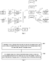
- Fig. 1 is a structural diagram of a position detection apparatus of a distribution object according to some embodiments of the present disclosure. As shown in Fig. 1 , only two of the plurality of ranging sensors, i.e., a first ranging sensor 11 and a second ranging sensor 12, and a controller 13, are displayed in this embodiment.
- a first ranging sensor 11 and a second ranging sensor 12 and a controller 13 are displayed in this embodiment.
- the first ranging sensor 11 and the second ranging sensor 12 may be located on an end surface of a protrusion member 21 of a robot facing a placement region of a distribution object.
- the robot comprises, for example, the protrusion member 21 and a chassis 22, and the protrusion member 21 is arranged on the chassis 22.
- the end surface of the protrusion member 21 facing the placement region of the distribution object is arranged perpendicular to the chassis 22.
- the protrusion member 21 may be arranged at a front or rear end of the chassis 22 in a traversing direction.
- the protrusion member 21 may be a head protruding relative to the chassis 22.
- the distribution object is, for example, a distribution vehicle.
- the distribution vehicle can be provided with legs and moving devices.
- the moving devices are universal wheels.
- a projection of the first ranging sensor 11 on the chassis 22 does not overlap a projection of the second ranging sensor 12 on the chassis 22.
- a distance between the projection of the first ranging sensor 11 on the chassis 22 and the projection of the second ranging sensor 12 on the chassis 22 is not less than a second distance threshold.
- the first ranging sensor 11 and the second ranging sensor 12 are respectively located on a left side and a right side of the end surface of the protrusion member 21 of the robot facing the placement region of the distribution object, which can monitor a distance and an angle between opposite end surfaces of the distribution object and the protrusion member in real time, so as to ensure that the opposite end surfaces of the distribution object and the distribution object are parallel to each other.
- each of the first ranging sensor 11 and the second ranging sensor 12 is configured to detect a distance between each of the first ranging sensor 11 and the second ranging sensor 12 and the end surface of the distribution object facing the plurality of ranging sensors, and transmits the detected distance to the controller 13.
- the first distance sensor 11 transmits a detected first distance to the controller 13
- the second distance sensor 12 transmits a detected second distance to the controller 13.
- the first ranging sensor 11 and the second ranging sensor 12 are, for example, infrared ranging sensors.
- a measuring range of each of the infrared ranging sensors is 1 to 100cm.
- the each of the infrared ranging sensors sensor will output a distance from the obstruction to the each of the infrared ranging sensors.
- the distance detected by the each of the infrared ranging sensors will gradually decrease with the proximity of the distribution vehicle.
- the first ranging sensor 11 outputs the detected first distance in a form of an analog voltage.
- a driving capacity of the analog voltage output from the first ranging sensor 11 is increased through a first voltage follower 41.
- a voltage signal output by the first voltage follower 41 is input to a first operational amplifier 42, which amplifies the analog voltage carrying the first distance information, and inputs it to a first ADC (analog-to-digital converter) 43.
- the first ranging sensor 12 outputs the detected second distance in the form of an analog voltage.
- a driving capacity of the analog voltage output from the second ranging sensor 12 is increased through a second voltage follower 44.
- a voltage signal output by the second voltage follower 44 is input to a second operational amplifier 45, which amplifies the analog voltage carrying the second distance information, and inputs it to the first ADC 43.
- the first ADC 43 converts the analog voltages to digital values and inputs them to the controller 13 through a SPI (Serial Peripheral Interface).
- the controller 13 is configured to determine whether the distribution object has been located at a predetermined position above the chassis 22 of the robot according to the distance detected by each of the plurality of ranging sensors.
- the controller 13 is configured to determine that the distribution object has been located at a predetermined position above the chassis 22 in a case of determining that the first distance detected by the first ranging sensor 11 is not greater than a first distance threshold and the second distance detected by the second ranging sensor 12 is not greater than the first distance threshold.
- the first distance and the second distance detected by the first ranging sensor 11 and the second ranging sensor 12 are both not greater than 4cm, it indicates that the distribution object has been located at a predetermined position above the chassis 22. If the distance detected by the first ranging sensor 11 is 10cm and the distance detected by the second ranging sensor 12 is 4cm, it indicates that the distribution object is inclined or there is interference, and an adjustment should be made in time to place the distribution object to the predetermined position above the chassis 22.
- the controller 13 transmits an instruction to the jacking mechanism 23 to lift the distribution object. For example, the controller 13 transmits an instruction to a motor driver 231 of the jacking mechanism 23 to control a jacking motor 232 to rotate, so that a push rod 233 of the jacking mechanism is pushed upward to lift the distribution object off the ground.
- the plurality of ranging sensors are arranged on the end surface of the protrusion member of the robot facing the distribution object; each of the plurality of ranging sensors detects the distance between the each of the plurality of ranging sensors and the end surface of the distribution object facing the plurality of ranging sensors; and whether the distribution object is located at a predetermined position above the chassis of the robot according to the distance detected by the each of the plurality of ranging sensors is determined.
- the position detection apparatus of the distribution object of the embodiment of the present disclosure can improve an accuracy of detecting whether the distribution object is located at the predetermined position above the robot, thereby reducing a loss in a transportation process.
- the first ranging sensor 11 and the second ranging sensor 12 respectively transmit the detected first distance and the second distance to the controller 13 in real time. If the first distance or the second distance changes, it indicates that the distribution object is at risk of shaking or falling off, and the controller 13 can transmit an alarm signal in time, thereby reducing the loss caused by falling off of the distribution object.
- the position detection apparatus of the distribution object further comprises a pressure sensor 14 arranged on the jacking mechanism 23 and configured to transmit information of a detected pressure on the jacking mechanism 23 to the controller 13; the controller 13 is further configured to send an instruction to the jacking mechanism 23 to stop lifting the distribution object in a case of determining that the detected pressure is greater than a pressure threshold.
- the pressure sensor 14 located on the jacking mechanism 23 outputs a value of a detected pressure on the jacking mechanism in the form of an analog voltage signal.
- the analog voltage signal is input to the controller 13 through a third operational amplifier 46 and a second ADC 47.
- the controller 13 resolves the value of the detected pressure on the jacking mechanism. If the distribution object is overweight, the controller 13 sends an instruction to the motor driver 231 of the jacking mechanism 23 to control the jacking motor 232 to stop operation and give an alarm to a master computer.
- the movement of the jacking mechanism is stopped to prevent overload, thereby reducing a probability of danger during a transportation.
- the position detection apparatus of the distribution object further comprises: a first height detection sensor 15 configured to send a first signal to the controller 13 in a case of detecting that the jacking mechanism 23 has risen to a predetermined height; the controller 13 is further configured to send an instruction to the jacking mechanism 23 to stop lifting the distribution object in a case of receiving the first signal.
- the first height detection sensor 15 mounted in the jacking mechanism is triggered to send a switch signal at a certain moment.
- the switch signal is input to the controller 13.
- the controller 13 realizes that the push rod 233 has risen to a preset position, and sends an instruction to the motor driver 231 to control the jacking motor 232 to stop operation.
- the position detection apparatus of the distribution object further comprises: a second height detection sensor 16 configured to send a second signal to the controller 13 in a case of detecting that the jacking mechanism 23 has lowered to an initial position thereof; the controller 13 is further configured to send an instruction to the jacking mechanism 23 to stop lowering in a case of receiving the second signal.
- the controller 13 sends an instruction to the motor driver 231 to control the jacking motor 232 to operate to lower the push rod 233.
- the push rod 233 triggers the second height detection sensor 16 at the initial position to output a signal
- the signal after a comparison by a second comparator 49 is input to the controller 13.
- the controller 13 then realizes that the push rod 233 has lowered to the initial position, and sends an instruction to the motor driver 231 to control the jacking motor 232 to stop operation.
- each of the first height detection sensor 15 and the second height detection sensor 16 is an infrared pair diode.
- a infrared pair diode comprises a light-emitting diode and a photodiode. Measurement data is output when there is a barrier between the light-emitting diode and the photodiode.
- a blank may be disposed on the push rod, and the infrared pair diode is arranged on both sides of the blank. When the blank moves to the position of the infrared pair diode, the infrared pair diode can output measurement data.
- the jacking mechanism can be prevented from raising too high and lowering too much.
- a robot comprising the position detection apparatus of the distribution object described above.
- a distribution apparatus comprising the robot described above and a distribution object, wherein the distribution object is detachably connected to the robot.
- the distribution object is, for example, a distribution vehicle.
- the distribution apparatus is applicable in hospitals and other places.
- the position of the distribution vehicle can be detected to ensure that the distribution vehicle is located in an appropriate position relative to the robot.
- the status of the distribution vehicle is monitored in real time to ensure that an alarm can be sent in time when the distribution vehicle encounters the risk of falling off from the robot, so as to reduce the loss.
- Fig. 5 is a structural diagram of a position detection method of a distribution object according to some embodiments of the present disclosure.
- a controller receives a distance between each of a plurality of ranging sensors and an end surface of a distribution object facing the plurality of ranging sensors from the each of the plurality of ranging sensors, wherein the plurality of ranging sensors are arranged on an end surface of a protrusion member of a robot facing a placement region of the distribution object.
- step 520 the controller determines that the distribution object has been located at a predetermined position above the chassis in a case where the distance detected by each of the plurality of ranging sensors is not greater than a first distance threshold.
- the plurality of ranging sensors are arranged on the end surface of the protrusion member of the robot facing the distribution object; each of the plurality of ranging sensors detects the distance between the each of the plurality of ranging sensors and the end surface of the distribution object facing the plurality of ranging sensors; and whether the distribution object is located at a predetermined position above the chassis of the robot according to the distance detected by the each of the plurality of ranging sensors is determined.
- the position detection apparatus of the distribution object of the embodiment of the present disclosure can improve an accuracy of detecting whether the distribution object is located at the predetermined position above the robot, thereby reducing a loss in a transportation process.
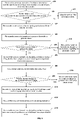
- the plurality of ranging sensors comprise a first ranging sensor and a second ranging sensor, and a robot is engaged in transporting a distribution vehicle as an example, the scheme of the present disclosure will be described below.
- the first distance sensor transmits a first distance detected between the first ranging sensor and an end surface of a distribution object facing the first ranging sensor to a controller
- the second distance sensor transmits a second distance detected between the second ranging sensor and an end surface of a distribution object facing the second ranging sensor to the controller.
- step 620 the controller determines whether the first distance and the second distance are not greater than a first distance threshold; if so, step 630 is executed; otherwise, step 631 is executed.
- step 630 the controller sends an instruction to a jacking mechanism to lift the distribution vehicle.
- the distribution vehicle has been already at a predetermined position above the chassis of the robot.
- step 631 the position of the distribution vehicle is adjusted.
- step 640 the controller receives information of a pressure detected by a pressure sensor.
- step 650 the controller determines whether the pressure is greater than a pressure threshold; if so, step 660 is executed; otherwise, step 670 is executed.
- step 660 the controller sends an instruction to the jacking mechanism to stop lifting the distribution vehicle.
- step 670 the controller sends an instruction to the jacking mechanism to stop lifting the distribution object in a case of receiving a first signal sent from a first height sensor; wherein the first height detection sensor sends a first signal to the controller in a case of detecting that the jacking mechanism has risen to a predetermined height.
- step 680 the controller sends an operation instruction to the robot.
- the robot transports the distribution vehicle along a preset path.
- step 690 the controller determines whether the first distance or the second distance has changed in real time; if so, step 6100 is executed; otherwise, step 690 is executed.
- step 6100 the controller sends alarm information to adjust the position of the distribution vehicle in time.
- step 6110 the controller detects that the robot has traveled to its destination, and sends a stop operation instruction to the robot.
- step 6120 the controller sends a lowering instruction to the jacking mechanism.
- step 6130 the controller sends an instruction to the jacking mechanism to stop lowering in a case of receiving a second signal sent from a second height sensor; wherein the second height detection sensor sends the second signal to the controller in a case of detecting that the jacking mechanism has lowered to an initial position thereof. At this point, the jacking mechanism stops moving.
- the plurality of sensors on the robot detect the position of the distribution vehicle relative to the robot in real time. Upon ensuring that the distribution vehicle has been accurately located at the predetermined position relative to the robot, the distribution vehicle is lifted and transported to the destination. Because the vehicle state can be monitored in real time, the risk of falling off of the distribution vehicle during transportation can be reduced.
- Fig. 7 is a schematic structural diagram of a controller according to some embodiments of the present disclosure.
- the controller comprises: a memory 710 and a processor 720, wherein the memory 710 may be a magnetic disk, flash memory or any other non-volatile storage medium.
- the memory is used to store instructions of corresponding embodiments shown in Figs. 5 and 6 .
- the processor 720 is coupled to memory 710 and may be implemented as one or more integrated circuits, such as a microprocessor or microcontroller.
- the processor 720 is used to execute the instructions stored in the memory.
- the controller 800 includes a memory 810 and a processor 820.
- the processor 820 is coupled to the memory 810 via a bus 830.
- the controller 800 may be further connected to an external storage device 850 through a storage interface 840 to access external data, and may be further connected to a network or another computer system (not shown) through a network interface 860, which will not be described in detail herein.
- an accuracy of detecting whether the distribution object is located at a predetermined position above the robot can be improved, thereby reducing a loss in a transportation process.
- a computer-readable storage medium is provided, with computer program instructions stored thereon that, when executed by a processor, implement the steps of the methods of corresponding embodiments shown in Figs. 5 and 6 .
- a processor may be provided as a method, a system, or a computer program product. Therefore, embodiments of the present disclosure can take the form of an entirely hardware embodiment, an entirely software embodiment or an embodiment containing both hardware and software elements.
- the present disclosure may take the form of a computer program product embodied on one or more computer-usable non-transitory storage media (including but not limited to disk storage, CD-ROM, optical memory, etc.) having computer-usable program code embodied therein.
- the present disclosure is described with reference to flowcharts and/or block diagrams of methods, apparatuses (systems) and computer program products according to embodiments of the present disclosure. It should be understood that each process and/or block in the flowcharts and/or block diagrams, and combinations of the processes and/or blocks in the flowcharts and/or block diagrams may be implemented by computer program instructions.
- the computer program instructions may be provided to a processor of a general purpose computer, a special purpose computer, an embedded processor, or other programmable data processing device to generate a machine such that the instructions executed by a processor of a computer or other programmable data processing device to generate means implementing the functions specified in one or more flows of the flowcharts and/or one or more blocks of the block diagrams.
- the computer program instructions may also be stored in a computer readable memory device capable of directing a computer or other programmable data processing device to operate in a specific manner such that the instructions stored in the computer readable memory device produce an object of manufacture including instruction means implementing the functions specified in one or more flows of the flowcharts and/or one or more blocks of the block diagrams.
Landscapes
- Engineering & Computer Science (AREA)
- Transportation (AREA)
- Structural Engineering (AREA)
- Mechanical Engineering (AREA)
- Life Sciences & Earth Sciences (AREA)
- Geology (AREA)
- Civil Engineering (AREA)
- Physics & Mathematics (AREA)
- General Physics & Mathematics (AREA)
- Radar, Positioning & Navigation (AREA)
- Remote Sensing (AREA)
- Electromagnetism (AREA)
- Robotics (AREA)
- Chemical & Material Sciences (AREA)
- Combustion & Propulsion (AREA)
- Manipulator (AREA)
Applications Claiming Priority (2)
| Application Number | Priority Date | Filing Date | Title |
|---|---|---|---|
| CN201910881295.0A CN110589505B (zh) | 2019-09-18 | 2019-09-18 | 配送物到位检测装置、方法、机器人、配送设备和控制器 |
| PCT/CN2020/114906 WO2021052264A1 (zh) | 2019-09-18 | 2020-09-11 | 配送物到位检测装置、方法、机器人、配送设备和控制器 |
Publications (2)
| Publication Number | Publication Date |
|---|---|
| EP4005967A1 true EP4005967A1 (de) | 2022-06-01 |
| EP4005967A4 EP4005967A4 (de) | 2023-09-06 |
Family
ID=68860610
Family Applications (1)
| Application Number | Title | Priority Date | Filing Date |
|---|---|---|---|
| EP20864806.3A Pending EP4005967A4 (de) | 2019-09-18 | 2020-09-11 | Gerät und verfahren zur detektion der platzierung von verteilartikeln, roboter, verteilvorrichtung und steuerung |
Country Status (4)
| Country | Link |
|---|---|
| US (1) | US12434925B2 (de) |
| EP (1) | EP4005967A4 (de) |
| CN (1) | CN110589505B (de) |
| WO (1) | WO2021052264A1 (de) |
Families Citing this family (12)
| Publication number | Priority date | Publication date | Assignee | Title |
|---|---|---|---|---|
| CN110589505B (zh) * | 2019-09-18 | 2020-12-22 | 北京海益同展信息科技有限公司 | 配送物到位检测装置、方法、机器人、配送设备和控制器 |
| CN111267996A (zh) * | 2020-02-17 | 2020-06-12 | 北京海益同展信息科技有限公司 | 运送机器人 |
| CN111438690A (zh) * | 2020-04-03 | 2020-07-24 | 北京海益同展信息科技有限公司 | 配送机器人、配送机器人的控制方法、装置及存储介质 |
| CN111638720A (zh) * | 2020-05-27 | 2020-09-08 | 北京海益同展信息科技有限公司 | 升降平台的控制方法、装置、设备、介质及配送机器人 |
| CN114655732B (zh) * | 2020-12-23 | 2024-11-08 | 北醒(北京)光子科技有限公司 | 一种基于激光雷达的无人装车系统 |
| JP7517187B2 (ja) * | 2021-02-03 | 2024-07-17 | トヨタ自動車株式会社 | 運搬システム、制御方法、及びプログラム |
| CN113241651B (zh) * | 2021-06-01 | 2022-10-04 | 广东电网有限责任公司 | 一种手车式开关柜用转运小车 |
| JP7468503B2 (ja) * | 2021-12-28 | 2024-04-16 | トヨタ自動車株式会社 | 搬送ロボット |
| CN114684426B (zh) * | 2022-06-01 | 2022-08-12 | 江苏璞丽达数码科技有限公司 | 纸制品自动化包装装置 |
| CN115931389B (zh) * | 2022-12-26 | 2026-03-13 | 北京百度网讯科技有限公司 | 移动底盘、安装系统、物体对接方法及自动驾驶测试方法 |
| JP2024164722A (ja) * | 2023-05-15 | 2024-11-27 | パナソニックIpマネジメント株式会社 | ロボット |
| CN119224603B (zh) * | 2024-11-28 | 2025-03-18 | 元能科技(厦门)有限公司 | 软包扣电膨胀性能快速测试方法、设备、介质和程序产品 |
Family Cites Families (18)
| Publication number | Priority date | Publication date | Assignee | Title |
|---|---|---|---|---|
| JP2599065B2 (ja) * | 1992-01-31 | 1997-04-09 | 小松フォークリフト株式会社 | フォークリフトのサイドシフト装置 |
| US6543983B1 (en) * | 1998-07-07 | 2003-04-08 | University Of Virginia Patent Foundation | Robotic pick up and deliver system |
| JP4331453B2 (ja) * | 2002-09-30 | 2009-09-16 | セコム株式会社 | 搬送ロボット |
| US7699141B2 (en) * | 2006-03-20 | 2010-04-20 | Fossier David A | Pallet distance ranging device for forklift |
| KR101665725B1 (ko) * | 2010-12-22 | 2016-10-12 | 주식회사 두산 | 지게차용 인칭 자동제어 시스템 |
| US20170015537A1 (en) * | 2015-07-13 | 2017-01-19 | George R. Bosworth, III | Lifting fork positioning system |
| US10048398B2 (en) * | 2016-10-31 | 2018-08-14 | X Development Llc | Methods and systems for pallet detection |
| EP3339238B1 (de) * | 2016-12-23 | 2023-09-20 | The Raymond Corporation | Systeme und verfahren zur bestimmung eines warenregals, für ein materialhandhabungsfahrzeug |
| CN106853640A (zh) * | 2017-03-21 | 2017-06-16 | 北京京东尚科信息技术有限公司 | 配送机器人控制方法和装置、配送机器人及控制系统 |
| US10328578B2 (en) * | 2017-04-21 | 2019-06-25 | X Development Llc | Methods and systems for detecting, recognizing, and localizing pallets |
| CN207108377U (zh) * | 2017-05-25 | 2018-03-16 | 合肥柯金自动化科技股份有限公司 | 激光导引叉车agv取货机构 |
| CN108046172A (zh) * | 2017-12-04 | 2018-05-18 | 深圳市今天国际物流技术股份有限公司 | 叉车机器人 |
| CN208292587U (zh) * | 2018-05-10 | 2018-12-28 | 比亚迪股份有限公司 | 叉车 |
| CN208327296U (zh) * | 2018-06-29 | 2019-01-04 | 湖南三一港口设备有限公司 | 一种防挂箱安全保护装置、集装箱装卸设备 |
| CN109178759A (zh) * | 2018-07-19 | 2019-01-11 | 长沙格力暖通制冷设备有限公司 | 空中物流方法、装置、物流设备及计算机可读存储介质 |
| CN108946586A (zh) * | 2018-09-14 | 2018-12-07 | 浙江斐尔德智能设备有限公司 | 多功能型自动导引运输车 |
| CN109726962A (zh) * | 2018-12-29 | 2019-05-07 | 拉扎斯网络科技(上海)有限公司 | 无人配送设备、配送机器人调度方法、装置、设备及介质 |
| CN110589505B (zh) * | 2019-09-18 | 2020-12-22 | 北京海益同展信息科技有限公司 | 配送物到位检测装置、方法、机器人、配送设备和控制器 |
-
2019
- 2019-09-18 CN CN201910881295.0A patent/CN110589505B/zh active Active
-
2020
- 2020-09-11 WO PCT/CN2020/114906 patent/WO2021052264A1/zh not_active Ceased
- 2020-09-11 US US17/639,156 patent/US12434925B2/en active Active
- 2020-09-11 EP EP20864806.3A patent/EP4005967A4/de active Pending
Also Published As
| Publication number | Publication date |
|---|---|
| US12434925B2 (en) | 2025-10-07 |
| EP4005967A4 (de) | 2023-09-06 |
| WO2021052264A1 (zh) | 2021-03-25 |
| CN110589505A (zh) | 2019-12-20 |
| US20220332526A1 (en) | 2022-10-20 |
| CN110589505B (zh) | 2020-12-22 |
Similar Documents
| Publication | Publication Date | Title |
|---|---|---|
| US12434925B2 (en) | Position detection apparatus and method of distribution object, robot, distribution apparatus, and controller | |
| US11851310B2 (en) | Autonomous forklift truck | |
| US9828223B2 (en) | Fork-lift truck and method for operating a fork-lift truck | |
| CN112758852B (zh) | 用于无人驾驶地、自主地反应地运行的地面运输工具 | |
| EP3511678B1 (de) | Systeme und verfahren zur odometriekalibrierung eines materialhandhabungsfahrzeugs | |
| US20180120465A1 (en) | Methods and Systems for Pallet Detection | |
| US20160090283A1 (en) | Fork-Lift Truck | |
| US11597641B2 (en) | Industrial truck and method for operating the same | |
| JP5397839B2 (ja) | 搬送車両システム | |
| EP3291039B1 (de) | Artikelbeförderungseinrichtung | |
| BR112012003579A2 (pt) | método para aplicar automaticamente uma manobra de correção da direção em um veículo de manipulação de materiais, e, veículo de manipulação de materiais | |
| EP3771955B1 (de) | System und verfahren zum betreiben eines autonomen mobilen roboters basierend auf nutzlasterfassung | |
| US20240124228A1 (en) | Conveyance system, conveyance method, and program | |
| EP3656702A1 (de) | Mobiler industrieroboter mit sicherheitssystem zur palettenregistrierung | |
| JP2015178759A (ja) | 駐車システム | |
| CN115027901B (zh) | 运输系统、运输方法和存储介质 | |
| US11952247B1 (en) | Control system for an electric pallet jack | |
| CN208361820U (zh) | 能够自动判定抬升高度的agv堆高机 | |
| CN115432646A (zh) | 堆高机及其控制方法 | |
| US20230226940A1 (en) | Multi-Function Rack Systems and Methods | |
| US20260037002A1 (en) | Autonomous forklift truck for lifting and transporting a load, and associated method | |
| CN114967671B (zh) | 运输系统、运输方法和计算机可读存储介质 | |
| US20240343539A1 (en) | Transfer robot, control method therefor, and non-transitory storage medium | |
| CN212425333U (zh) | 一种托盘联动校准装置 | |
| US20250340416A1 (en) | Path specification system, path specification apparatus, and path specification method |
Legal Events
| Date | Code | Title | Description |
|---|---|---|---|
| STAA | Information on the status of an ep patent application or granted ep patent |
Free format text: STATUS: THE INTERNATIONAL PUBLICATION HAS BEEN MADE |
|
| PUAI | Public reference made under article 153(3) epc to a published international application that has entered the european phase |
Free format text: ORIGINAL CODE: 0009012 |
|
| STAA | Information on the status of an ep patent application or granted ep patent |
Free format text: STATUS: REQUEST FOR EXAMINATION WAS MADE |
|
| 17P | Request for examination filed |
Effective date: 20220228 |
|
| AK | Designated contracting states |
Kind code of ref document: A1 Designated state(s): AL AT BE BG CH CY CZ DE DK EE ES FI FR GB GR HR HU IE IS IT LI LT LU LV MC MK MT NL NO PL PT RO RS SE SI SK SM TR |
|
| DAV | Request for validation of the european patent (deleted) | ||
| DAX | Request for extension of the european patent (deleted) | ||
| A4 | Supplementary search report drawn up and despatched |
Effective date: 20230807 |
|
| RIC1 | Information provided on ipc code assigned before grant |
Ipc: B66F 9/07 20060101AFI20230801BHEP |
|
| STAA | Information on the status of an ep patent application or granted ep patent |
Free format text: STATUS: EXAMINATION IS IN PROGRESS |
|
| 17Q | First examination report despatched |
Effective date: 20241114 |