EP4005985A1 - Sauerstoffbrennstoffbrenner für ein vorherdsystem - Google Patents
Sauerstoffbrennstoffbrenner für ein vorherdsystem Download PDFInfo
- Publication number
- EP4005985A1 EP4005985A1 EP21206458.8A EP21206458A EP4005985A1 EP 4005985 A1 EP4005985 A1 EP 4005985A1 EP 21206458 A EP21206458 A EP 21206458A EP 4005985 A1 EP4005985 A1 EP 4005985A1
- Authority
- EP
- European Patent Office
- Prior art keywords
- oxygen
- fuel
- burner
- forehearth
- pipe
- Prior art date
- Legal status (The legal status is an assumption and is not a legal conclusion. Google has not performed a legal analysis and makes no representation as to the accuracy of the status listed.)
- Pending
Links
Images


Classifications
-
- C—CHEMISTRY; METALLURGY
- C03—GLASS; MINERAL OR SLAG WOOL
- C03B—MANUFACTURE, SHAPING, OR SUPPLEMENTARY PROCESSES
- C03B5/00—Melting in furnaces; Furnaces so far as specially adapted for glass manufacture
- C03B5/16—Special features of the melting process; Auxiliary means specially adapted for glass-melting furnaces
- C03B5/235—Heating the glass
- C03B5/2353—Heating the glass by combustion with pure oxygen or oxygen-enriched air, e.g. using oxy-fuel burners or oxygen lances
-
- F—MECHANICAL ENGINEERING; LIGHTING; HEATING; WEAPONS; BLASTING
- F23—COMBUSTION APPARATUS; COMBUSTION PROCESSES
- F23D—BURNERS
- F23D14/00—Burners for combustion of a gas, e.g. of a gas stored under pressure as a liquid
- F23D14/32—Burners for combustion of a gas, e.g. of a gas stored under pressure as a liquid using a mixture of gaseous fuel and pure oxygen or oxygen-enriched air
-
- F—MECHANICAL ENGINEERING; LIGHTING; HEATING; WEAPONS; BLASTING
- F23—COMBUSTION APPARATUS; COMBUSTION PROCESSES
- F23L—SUPPLYING AIR OR NON-COMBUSTIBLE LIQUIDS OR GASES TO COMBUSTION APPARATUS IN GENERAL ; VALVES OR DAMPERS SPECIALLY ADAPTED FOR CONTROLLING AIR SUPPLY OR DRAUGHT IN COMBUSTION APPARATUS; INDUCING DRAUGHT IN COMBUSTION APPARATUS; TOPS FOR CHIMNEYS OR VENTILATING SHAFTS; TERMINALS FOR FLUES
- F23L7/00—Supplying non-combustible liquids or gases, other than air, to the fire, e.g. oxygen, steam
- F23L7/007—Supplying oxygen or oxygen-enriched air
-
- F—MECHANICAL ENGINEERING; LIGHTING; HEATING; WEAPONS; BLASTING
- F23—COMBUSTION APPARATUS; COMBUSTION PROCESSES
- F23M—CASINGS, LININGS, WALLS OR DOORS SPECIALLY ADAPTED FOR COMBUSTION CHAMBERS, e.g. FIREBRIDGES; DEVICES FOR DEFLECTING AIR, FLAMES OR COMBUSTION PRODUCTS IN COMBUSTION CHAMBERS; SAFETY ARRANGEMENTS SPECIALLY ADAPTED FOR COMBUSTION APPARATUS; DETAILS OF COMBUSTION CHAMBERS, NOT OTHERWISE PROVIDED FOR
- F23M5/00—Casings; Linings; Walls
- F23M5/02—Casings; Linings; Walls characterised by the shape of the bricks or blocks used
- F23M5/025—Casings; Linings; Walls characterised by the shape of the bricks or blocks used specially adapted for burner openings
-
- F—MECHANICAL ENGINEERING; LIGHTING; HEATING; WEAPONS; BLASTING
- F27—FURNACES; KILNS; OVENS; RETORTS
- F27D—DETAILS OR ACCESSORIES OF FURNACES, KILNS, OVENS OR RETORTS, IN SO FAR AS THEY ARE OF KINDS OCCURRING IN MORE THAN ONE KIND OF FURNACE
- F27D99/00—Subject matter not provided for in other groups of this subclass
- F27D99/0001—Heating elements or systems
- F27D99/0033—Heating elements or systems using burners
-
- C—CHEMISTRY; METALLURGY
- C03—GLASS; MINERAL OR SLAG WOOL
- C03B—MANUFACTURE, SHAPING, OR SUPPLEMENTARY PROCESSES
- C03B2211/00—Heating processes for glass melting in glass melting furnaces
- C03B2211/20—Submerged gas heating
- C03B2211/22—Submerged gas heating by direct combustion in the melt
- C03B2211/23—Submerged gas heating by direct combustion in the melt using oxygen, i.e. pure oxygen or oxygen-enriched air
-
- C—CHEMISTRY; METALLURGY
- C03—GLASS; MINERAL OR SLAG WOOL
- C03B—MANUFACTURE, SHAPING, OR SUPPLEMENTARY PROCESSES
- C03B7/00—Distributors for the molten glass; Means for taking-off charges of molten glass; Producing the gob, e.g. controlling the gob shape, weight or delivery tact
- C03B7/02—Forehearths, i.e. feeder channels
- C03B7/06—Means for thermal conditioning or controlling the temperature of the glass
-
- F—MECHANICAL ENGINEERING; LIGHTING; HEATING; WEAPONS; BLASTING
- F23—COMBUSTION APPARATUS; COMBUSTION PROCESSES
- F23D—BURNERS
- F23D14/00—Burners for combustion of a gas, e.g. of a gas stored under pressure as a liquid
- F23D14/20—Non-premix gas burners, i.e. in which gaseous fuel is mixed with combustion air on arrival at the combustion zone
- F23D14/22—Non-premix gas burners, i.e. in which gaseous fuel is mixed with combustion air on arrival at the combustion zone with separate air and gas feed ducts, e.g. with ducts running parallel or crossing each other
-
- F—MECHANICAL ENGINEERING; LIGHTING; HEATING; WEAPONS; BLASTING
- F23—COMBUSTION APPARATUS; COMBUSTION PROCESSES
- F23D—BURNERS
- F23D2900/00—Special features of, or arrangements for burners using fluid fuels or solid fuels suspended in a carrier gas
- F23D2900/11403—Flame surrounding tubes in front of burner nozzle
-
- F—MECHANICAL ENGINEERING; LIGHTING; HEATING; WEAPONS; BLASTING
- F23—COMBUSTION APPARATUS; COMBUSTION PROCESSES
- F23M—CASINGS, LININGS, WALLS OR DOORS SPECIALLY ADAPTED FOR COMBUSTION CHAMBERS, e.g. FIREBRIDGES; DEVICES FOR DEFLECTING AIR, FLAMES OR COMBUSTION PRODUCTS IN COMBUSTION CHAMBERS; SAFETY ARRANGEMENTS SPECIALLY ADAPTED FOR COMBUSTION APPARATUS; DETAILS OF COMBUSTION CHAMBERS, NOT OTHERWISE PROVIDED FOR
- F23M2900/00—Special features of, or arrangements for combustion chambers
- F23M2900/05021—Wall blocks adapted for burner openings
-
- F—MECHANICAL ENGINEERING; LIGHTING; HEATING; WEAPONS; BLASTING
- F27—FURNACES; KILNS; OVENS; RETORTS
- F27D—DETAILS OR ACCESSORIES OF FURNACES, KILNS, OVENS OR RETORTS, IN SO FAR AS THEY ARE OF KINDS OCCURRING IN MORE THAN ONE KIND OF FURNACE
- F27D99/00—Subject matter not provided for in other groups of this subclass
- F27D99/0001—Heating elements or systems
- F27D99/0033—Heating elements or systems using burners
- F27D2099/004—Heating elements or systems using burners directed upon the charge, e.g. vertically
- F27D2099/0041—Heating elements or systems using burners directed upon the charge, e.g. vertically with a small angle, e.g. almost tangentially
-
- Y—GENERAL TAGGING OF NEW TECHNOLOGICAL DEVELOPMENTS; GENERAL TAGGING OF CROSS-SECTIONAL TECHNOLOGIES SPANNING OVER SEVERAL SECTIONS OF THE IPC; TECHNICAL SUBJECTS COVERED BY FORMER USPC CROSS-REFERENCE ART COLLECTIONS [XRACs] AND DIGESTS
- Y02—TECHNOLOGIES OR APPLICATIONS FOR MITIGATION OR ADAPTATION AGAINST CLIMATE CHANGE
- Y02E—REDUCTION OF GREENHOUSE GAS [GHG] EMISSIONS, RELATED TO ENERGY GENERATION, TRANSMISSION OR DISTRIBUTION
- Y02E20/00—Combustion technologies with mitigation potential
- Y02E20/34—Indirect CO2mitigation, i.e. by acting on non CO2directly related matters of the process, e.g. pre-heating or heat recovery
Definitions
- Disclosed aspects relate to oxygen fuel burners for a forehearth system of a glass manufacturing system.
- a glass manufacturing system is used in the production of glass, where molten glass is produced in a glass melting furnace which then passes along a forehearth system (or forehearth section) in a continuous stream to a feeder bowl from which the molten glass is fed in mold charges or gobs into a glass forming apparatus.
- the glass forming apparatus processes the molten glass received into a desired form or shape.
- the forehearth system is designed to condition the molten glass during conveyance between the glass melting furnace and the glass forming apparatus, rendering the molten glass more suitable for forming or shaping.
- the forehearth system is designed to heat or cool the molten glass to the temperature required for processing by the glass forming apparatus.
- the temperature of the molten glass after processing by the forehearth system needs to be maintained within about 1° C of a target temperature, such as around 1200° C, at the inlet to the glass forming apparatus.
- Conventional forehearth systems provide temperature control through a series of relatively small sized oxygen fuel forehearth burners placed longitudinally on either side of the forehearth duct.
- the spacing between the respective oxygen fuel forehearth burners is typically between six and eighteen inches.
- a single forehearth system can contain several hundred oxygen fuel forehearth burners and a single glass furnace may have one or multiple forehearth systems.
- a typical forehearth system comprises a refractory material (e.g., Alumina Zircon Silica) trough along which the molten glass flows, and which is generally provided with a thermally insulating crown or roof.
- Disclosed aspects recognize the forehearth system of a glass manufacturing system is in several ways more challenging to design for oxygen fuel forehearth burners as compared to designing a glass melting furnace. These design challenges include proper cooling of the oxygen fuel forehearth burner, and efficient and effective management of the discharge velocities of the fuel and the oxygen.
- One disclosed aspect comprises a forehearth system comprising a superstructure including a plurality of refractory bricks that frame a molten glass tank.
- a burner block comprising a refractory material includes a discharge throat that extends to its distal end, where the burner block is within the superstructure above the molten glass tank.
- At least one oxygen fuel forehearth burner is within the burner block having a long axis along a length direction.
- a fuel pipe is within the burner body having a fuel inlet for receiving fuel on one end and a fuel outlet on an opposite end.
- An oxygen pipe is within the burner body having an oxygen inlet for receiving oxygen and an oxygen outlet.
- the oxygen pipe is positioned coaxially outside the fuel pipe. The fuel outlet extends beyond the oxygen pipe and the burner body so that the oxygen first reaching the fuel and thus a flame when operating is delayed until the discharge throat.
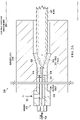
- FIG. 1 shows a cross-sectional view of an example oxygen fuel forehearth burner shown as 100 for the forehearth system section of a glass manufacturing system.
- the oxygen fuel forehearth burner 100 comprises a burner body 135 that typically comprises stainless steel.
- the oxygen fuel forehearth burner 100 is generally installed in a burner block comprising a refractory material, such as the burner block being positioned around the oxygen fuel forehearth burner 100.
- Example burner blocks are shown in FIGs. 2A and 2B described below.
- the oxygen fuel forehearth burner 100 generally also includes at least one flow controller for controlling the flow of the fuel and the flow of the oxygen.
- the arrangement shown for the oxygen fuel forehearth burner 100 is a coaxial pipe arrangement comprising an inner disposed fuel pipe 101 and an outer disposed oxygen pipe 102, where the fuel pipe 101 is contained inside the oxygen pipe 102.
- This arrangement delays the combustion process (reflected in the flame 107) for the oxygen fuel forehearth burner 100 so that combustion first occurs beyond the burner body 135 to be generally in the discharge throat of the burner block (see the burner blocks including a discharge throat shown in FIGs. 2A and 2B described below).
- the oxygen, or oxygen-containing gas enters its oxygen pipe 102 through an inlet path 103 formed through the burner body 135 shown optionally oriented at a right angle to the length direction of the oxygen fuel forehearth burner 100 and the oxygen pipe 102.
- the fuel enters the fuel pipe 101 axially (length direction) through a fuel inlet 104 also formed in the burner body 135.
- the fuel generally comprises natural gas known to be primarily methane, or propane, and the oxygen source generally comprises O 2 .
- the fuel pipe 101 can be seen to extend in the length direction 109 beyond the burner body 135 and beyond the oxygen pipe 102, generally a distance anywhere between 0.25" (inches) to 6" beyond the oxygen pipe 102.
- the flame 107 resulting from the combustion of the fuel with the oxygen generally has a low velocity laminar layer of O 2 105 shown surrounding flame 107. It may be possible for the discharge throat to be replaced by a direct discharge into the atmosphere.
- the laminar flow of fuel output by the fuel pipe 101 shown as 106 which is introduced near or at the center of the flame 107 emerging from the fuel outlet 101a, is generally moving at a velocity of 75 to 300 ft/s.
- Disclosed aspects recognize there are two factors which should be accounted for in a design of an oxygen fuel forehearth burner for a forehearth system for a glass manufacturing system.
- the function of the forehearth system comprising at least one oxygen fuel forehearth burner in a glass manufacturing system is to maintain the temperature of the molting glass, or to slightly cool the molten glass received from the glass melting furnace. It is recognized herein that the heat input needed for the forehearth system is significantly less as compared to the heat input needed for the glass melting furnace. This results in a lower volume of fuel and oxygen gas being passed through the oxygen fuel forehearth burner(s).
- This lower volume flow rate of reactant gas presents a challenge for oxygen fuel forehearth burners which are designed to be cooled almost entirely by the flow of reactants, the reactants being O 2 or an oxygen-containing gas mixture, and a fuel. As the flow rate of unburnt gases goes down, so does the total amount of heat that can be carried away from the oxygen fuel forehearth burner. This challenge is met by disclosed oxygen fuel forehearth burners as described below.
- an oxygen fuel forehearth burner 100 can be expected to remain within the operational limits of the materials of construction including the material of the burner body 135 which as noted above generally comprises stainless steel, at essentially every reasonable operating condition, and also operate normally for the life of the glass manufacturing system.
- the current state of the art for forehearth systems is recognized to also not adequately address the varied shapes of burner blocks that customers may use. It is common for customers to design their own forehearth burner blocks. When these customer-designed burner blocks are combined with a current state of the art oxygen fuel forehearth burner, it can cause unintended consequences. A poorly matched oxygen fuel forehearth burner and burner block can cause the oxygen fuel forehearth burner to prematurely fail due to excessively high temperatures in the burner block created by poor flow dynamics. Disclosed forehearths burners are generally essentially invariant to the particular shape of the burner block, generally ensuring cooler operation no matter the specific installation of the oxygen fuel forehearth burner.
- the forehearth system comprising at least one oxygen fuel forehearth burner transports the molten glass received from the glass melting furnace to the glass forming apparatus. Therefore, the forehearth system is recognized to be the last opportunity to affect the quality and the temperature of the glass. Temperature uniformity in the molten glass is recognized to be important for the forehearth system.
- the oxygen fuel forehearth burner can have a significant effect on both temperature control and temperature uniformity. If the oxygen fuel forehearth burner is designed for maximum flame luminosity, more of the heat produced by the combustion is absorbed by the top of the molten glass through thermal radiation. The top portion of the molten glass is thus recognized to need more heat input as compared to the bottom of the molten glass, which is in contact with the burner block. This creates a more uniform temperature for the molten glass being received by the glass forming apparatus.
- a luminous flame a burning flame which is brightly visible
- a disclosed oxygen fuel forehearth burner the generation of more useful heat generated per unit of fuel consumed. If one compares an oxygen fuel forehearth burner with a yellow luminous flame and an oxygen fuel forehearth burner with a blue flame, the oxygen fuel forehearth burner with the yellow luminous flame (relatively lower temperature) can be operated at a lower flow rate of both O 2 and fuel, and still heat the same volume of molten glass.
- the oxygen fuel forehearth burner does not overheat in the forehearth environment which can cause catastrophic damage to the oxygen fuel forehearth burner and also potentially to the glass batch moving through the furnace.
- the oxygen and the fuel should not be mixed in the oxygen fuel forehearth burner. This is because it is recognized there is generally not enough volume flow to eliminate the heat generated when using a metallic pipe as a combustion chamber for the oxygen fuel forehearth burner.
- Known oxygen fuel forehearth burners are recognized to not allow for the creation of a flame with maximum luminosity. In order to provide a maximum flame luminosity for an oxygen fuel forehearth burner, it is recognized herein that the flame should be configured to be relatively long and the fuel should be introduced to the oxygen at a relatively low velocity.
- the introduction of O 2 to the fuel as disclosed herein is delayed by the fuel pipe 101 extending beyond the burner body 135 into the discharge throat of the burner block.
- the point of fuel ignition is thus not the same as the point of O 2 injection.
- O 2 is instead injected into the oxygen fuel forehearth burner at the back of the oxygen fuel forehearth burner, while the fuel is not introduced until after the oxygen fuel forehearth burner (into the discharge throat), where the point of the fuel ignition should also be a sufficient distance from the burner body 135 of the oxygen fuel forehearth burner, this will also serve to keep the oxygen fuel forehearth burner cooler.
- the fuel velocity should be controlled to be within a defined velocity range, such as 75 to 300 ft/s.
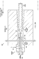
- FIGs. 2A and 2B each show a cross-sectional view of an arrangement shown as 200 and 250, respectively, showing a disclosed oxygen fuel forehearth burner shown as 100 positioned in a typical burner block for a forehearth system, with the burner blocks shown as 210 and 220, respectively.
- the burner blocks 210, 220 each are comprised of a refractory material (such as a ceramic or a refractory metal or refractory metal alloy), and for simplicity are shown having has a single oxygen fuel forehearth burner 100 positioned on the input side of the burner block.
- the burner blocks include discharge throat shown as 235 210 shown in FIG. 2A and a discharge throat 255 for the burner block 220 shown in FIG. 2B .
- the distal end of the discharge throats 235 and 235 are coupled to a forehearth system environment shown as 280. Molten glass will generally be below the burners blocks 210 and 220, such as shown in FIG. 4 described below.
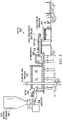
- FIG. 3 depicts an example glass manufacturing system 300 according to an example aspect.
- the glass manufacturing system 300 includes a raw material container 310 that provides unprocessed glass to a glass melting furnace 315, and there are a plurality of disclosed oxygen fuel forehearth burners 100 positioned in a burner block 320 that receives the melted glass output from the glass melting furnace 315, where the burner block 320 includes a discharge throat 235 or 255.
- the discharge throat 235 or 255 is coupled to a glass forming apparatus 330.
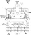
- a prototype oxygen fuel forehearth burner for a forehearth system resembling oxygen fuel forehearth burner 100 described above was built with the above-described features that was installed in a burner block 210 or 220 of the working forehearth system 400 depicted in FIG. 4 .
- the forehearth system 400 is shown including a superstructure comprising a plurality of refractory bricks 406, a burner block 210 or 220 within the superstructure above a molten glass tank 428 having molten glass therein shown as glass melt 431, and at least one oxygen fuel forehearth burner 100 positioned in the burner block 210 or 220.
- the refractory bricks 406 of the superstructure are configured to provide a crown (or roof) for 416, bottom 419, and sidewalls 417, where the bottom 419 and sidewalls 417 that define the molten glass tank 428, as well as for defining a cooling hole 418. There is a damper block 423 over the cooling hole 418.
- the customer replaced an entire zone of the forehearth system 400 with disclosed oxygen fuel forehearth burners resembling the design of the oxygen fuel forehearth burner 100 shown in FIG. 1 and using temperature sensors and flow sensors obtained various data points related to the oxygen fuel forehearth burners and glass melt.
- the customer also had oxygen fuel forehearth burners in the same forehearth system which follow the current state of the art.
- the current state of the art oxygen fuel forehearth burner introduces the O 2 and the fuel together inside the burner body and the flame is thus produced at the point in the burner body which the oxygen meets the fuel (which generally comprises natural gas).
- the internal structures of the current state of the art oxygen fuel forehearth burner introduces the oxygen and fuel together at relatively high velocities which is recognized herein to not be conducive to a luminous flame.
- FIG. 5A is a table summarizing these comparative oxygen fuel forehearth burner operating results. From this data, it is evidenced that for a disclosed oxygen fuel forehearth burner 100 the natural gas flow is about 2% lower when compared to the current state of the art oxygen fuel forehearth burner to maintain the same glass temperature.
- the glow from a disclosed oxygen fuel forehearth burner 100 is shown on the right where the flame can be seen beginning beyond the burner body, and the glow from a current state of the art oxygen fuel forehearth burner is shown on the left. On the left there was seen an orange glow for the flame shown emerging from the burner body of the oxygen fuel forehearth burner that indicated that the operational limits of the stainless steel of the burner body may have been surpassed.
- This current state of the art oxygen fuel forehearth burner will likely prematurely fail due to a reduced corrosion resistance and the physical weakening of the stainless steel of the burner body resulting from the excess temperature.
Landscapes
- Engineering & Computer Science (AREA)
- Chemical & Material Sciences (AREA)
- Combustion & Propulsion (AREA)
- Mechanical Engineering (AREA)
- General Engineering & Computer Science (AREA)
- Materials Engineering (AREA)
- Organic Chemistry (AREA)
- Glass Melting And Manufacturing (AREA)
- Gas Burners (AREA)
Applications Claiming Priority (1)
| Application Number | Priority Date | Filing Date | Title |
|---|---|---|---|
| US16/950,502 US20220153622A1 (en) | 2020-11-17 | 2020-11-17 | Oxygen fuel burner for a forehearth system |
Publications (1)
| Publication Number | Publication Date |
|---|---|
| EP4005985A1 true EP4005985A1 (de) | 2022-06-01 |
Family
ID=78528718
Family Applications (1)
| Application Number | Title | Priority Date | Filing Date |
|---|---|---|---|
| EP21206458.8A Pending EP4005985A1 (de) | 2020-11-17 | 2021-11-04 | Sauerstoffbrennstoffbrenner für ein vorherdsystem |
Country Status (4)
| Country | Link |
|---|---|
| US (1) | US20220153622A1 (de) |
| EP (1) | EP4005985A1 (de) |
| JP (2) | JP2022080292A (de) |
| CN (1) | CN114507001A (de) |
Citations (3)
| Publication number | Priority date | Publication date | Assignee | Title |
|---|---|---|---|---|
| US4986748A (en) * | 1989-12-15 | 1991-01-22 | Corning Incorporated | Wide range oxy-fuel burner and furnace operation |
| US6210151B1 (en) * | 1998-11-03 | 2001-04-03 | American Air Liquide | Self-cooled oxygen-fuel burner for use in high-temperature and high-particulate furnaces |
| EP2063175A1 (de) * | 2007-11-22 | 2009-05-27 | L'AIR LIQUIDE, Société Anonyme pour l'Etude et l'Exploitation des Procédés Georges Claude | Oxybrenner |
Family Cites Families (7)
| Publication number | Priority date | Publication date | Assignee | Title |
|---|---|---|---|---|
| US4897103A (en) * | 1988-09-12 | 1990-01-30 | Liberty Glass Company | Conduit for molten glass |
| FR2725017B1 (fr) * | 1994-09-22 | 1996-12-13 | Air Liquide | Ouvreau pour oxybruleur, ensemble d'oxybruleur comportant un tel ouvreau et procede de mise en oeuvre d'un tel ensemble |
| US6029910A (en) * | 1998-02-05 | 2000-02-29 | American Air Liquide, Inc. | Low firing rate oxy-fuel burner |
| FR2779806B1 (fr) * | 1998-06-15 | 2000-07-21 | Air Liquide | Bruleur a injecteur perfectionne et procede de fabrication de cet injecteur |
| JP4353619B2 (ja) * | 2000-06-26 | 2009-10-28 | 大阪瓦斯株式会社 | 炉加熱用バーナ |
| CN102803163B (zh) * | 2009-06-12 | 2015-11-25 | 气体产品与化学公司 | 用于控制熔融材料氧化状态的熔炉和方法 |
| JP2012102911A (ja) * | 2010-11-08 | 2012-05-31 | Air Liquide Japan Ltd | 燃焼バーナ |
-
2020
- 2020-11-17 US US16/950,502 patent/US20220153622A1/en not_active Abandoned
-
2021
- 2021-11-04 EP EP21206458.8A patent/EP4005985A1/de active Pending
- 2021-11-11 CN CN202111335001.8A patent/CN114507001A/zh active Pending
- 2021-11-15 JP JP2021185469A patent/JP2022080292A/ja active Pending
-
2023
- 2023-09-01 JP JP2023142000A patent/JP2023175724A/ja active Pending
Patent Citations (3)
| Publication number | Priority date | Publication date | Assignee | Title |
|---|---|---|---|---|
| US4986748A (en) * | 1989-12-15 | 1991-01-22 | Corning Incorporated | Wide range oxy-fuel burner and furnace operation |
| US6210151B1 (en) * | 1998-11-03 | 2001-04-03 | American Air Liquide | Self-cooled oxygen-fuel burner for use in high-temperature and high-particulate furnaces |
| EP2063175A1 (de) * | 2007-11-22 | 2009-05-27 | L'AIR LIQUIDE, Société Anonyme pour l'Etude et l'Exploitation des Procédés Georges Claude | Oxybrenner |
Also Published As
| Publication number | Publication date |
|---|---|
| JP2023175724A (ja) | 2023-12-12 |
| CN114507001A (zh) | 2022-05-17 |
| US20220153622A1 (en) | 2022-05-19 |
| JP2022080292A (ja) | 2022-05-27 |
Similar Documents
| Publication | Publication Date | Title |
|---|---|---|
| US5417732A (en) | Oxygen fired glass furnace with burners in the upstream end | |
| KR101117462B1 (ko) | 저 열용량 가스 산소 점화 버너 | |
| EP0436793B1 (de) | Brennstoffoxybrenner | |
| CA2313234C (en) | Roof-mounted oxygen-fuel burner for a glass melting furnace and process of using the oxygen-fuel burner | |
| US6074197A (en) | Combustion process and apparatus therefore containing separate injection of fuel and oxidant streams | |
| US6708527B1 (en) | Glass feeder operated with oxy-gas combustion | |
| US8769992B2 (en) | Panel-cooled submerged combustion melter geometry and methods of making molten glass | |
| US5490775A (en) | Forward injection oxy-fuel burner | |
| US7509819B2 (en) | Oxygen-fired front end for glass forming operation | |
| JP2749448B2 (ja) | 大量、低速、乱流火炎による炉の酸素/燃料燃焼 | |
| US3592622A (en) | Oxy-fuel accelerated glass melting furnace and method of operation | |
| EP2577168B1 (de) | Sauerstoff-brennstoff-brenner | |
| US20220074592A1 (en) | Assembly and method for injecting a gaseous combustion agent | |
| EP4005985A1 (de) | Sauerstoffbrennstoffbrenner für ein vorherdsystem | |
| US9074766B2 (en) | Combustion method and system | |
| US9046264B2 (en) | Method of controlling burners for heating liquid glass flow channels | |
| CN1186927A (zh) | 包括分开喷射燃料和氧化剂流的燃烧方法和设备 | |
| EP0484162A2 (de) | Verfahren und Vorrichtung zum Transportieren von geschmolzenem Glas |
Legal Events
| Date | Code | Title | Description |
|---|---|---|---|
| PUAI | Public reference made under article 153(3) epc to a published international application that has entered the european phase |
Free format text: ORIGINAL CODE: 0009012 |
|
| STAA | Information on the status of an ep patent application or granted ep patent |
Free format text: STATUS: REQUEST FOR EXAMINATION WAS MADE |
|
| 17P | Request for examination filed |
Effective date: 20211104 |
|
| AK | Designated contracting states |
Kind code of ref document: A1 Designated state(s): AL AT BE BG CH CY CZ DE DK EE ES FI FR GB GR HR HU IE IS IT LI LT LU LV MC MK MT NL NO PL PT RO RS SE SI SK SM TR |
|
| P01 | Opt-out of the competence of the unified patent court (upc) registered |
Effective date: 20230414 |
|
| STAA | Information on the status of an ep patent application or granted ep patent |
Free format text: STATUS: EXAMINATION IS IN PROGRESS |
|
| 17Q | First examination report despatched |
Effective date: 20250731 |