EP4006138A1 - Dispositif d'inspection de culture cellulaire rapide facilitant une observation précise - Google Patents
Dispositif d'inspection de culture cellulaire rapide facilitant une observation précise Download PDFInfo
- Publication number
- EP4006138A1 EP4006138A1 EP20923615.7A EP20923615A EP4006138A1 EP 4006138 A1 EP4006138 A1 EP 4006138A1 EP 20923615 A EP20923615 A EP 20923615A EP 4006138 A1 EP4006138 A1 EP 4006138A1
- Authority
- EP
- European Patent Office
- Prior art keywords
- fluid
- well
- sub
- cell culture
- test device
- Prior art date
- Legal status (The legal status is an assumption and is not a legal conclusion. Google has not performed a legal analysis and makes no representation as to the accuracy of the status listed.)
- Pending
Links
Images



Classifications
-
- C—CHEMISTRY; METALLURGY
- C12—BIOCHEMISTRY; BEER; SPIRITS; WINE; VINEGAR; MICROBIOLOGY; ENZYMOLOGY; MUTATION OR GENETIC ENGINEERING
- C12Q—MEASURING OR TESTING PROCESSES INVOLVING ENZYMES, NUCLEIC ACIDS OR MICROORGANISMS; COMPOSITIONS OR TEST PAPERS THEREFOR; PROCESSES OF PREPARING SUCH COMPOSITIONS; CONDITION-RESPONSIVE CONTROL IN MICROBIOLOGICAL OR ENZYMOLOGICAL PROCESSES
- C12Q1/00—Measuring or testing processes involving enzymes, nucleic acids or microorganisms; Compositions therefor; Processes of preparing such compositions
- C12Q1/02—Measuring or testing processes involving enzymes, nucleic acids or microorganisms; Compositions therefor; Processes of preparing such compositions involving viable microorganisms
- C12Q1/18—Testing for antimicrobial activity of a material
- C12Q1/20—Testing for antimicrobial activity of a material using multifield media
-
- B—PERFORMING OPERATIONS; TRANSPORTING
- B01—PHYSICAL OR CHEMICAL PROCESSES OR APPARATUS IN GENERAL
- B01L—CHEMICAL OR PHYSICAL LABORATORY APPARATUS FOR GENERAL USE
- B01L3/00—Containers or dishes for laboratory use, e.g. laboratory glassware; Droppers
- B01L3/50—Containers for the purpose of retaining a material to be analysed, e.g. test tubes
- B01L3/508—Rigid containers without fluid transport within
- B01L3/5085—Rigid containers without fluid transport within for multiple samples, e.g. microtitration plates
- B01L3/50853—Rigid containers without fluid transport within for multiple samples, e.g. microtitration plates with covers or lids
-
- C—CHEMISTRY; METALLURGY
- C12—BIOCHEMISTRY; BEER; SPIRITS; WINE; VINEGAR; MICROBIOLOGY; ENZYMOLOGY; MUTATION OR GENETIC ENGINEERING
- C12M—APPARATUS FOR ENZYMOLOGY OR MICROBIOLOGY; APPARATUS FOR CULTURING MICROORGANISMS FOR PRODUCING BIOMASS, FOR GROWING CELLS OR FOR OBTAINING FERMENTATION OR METABOLIC PRODUCTS, i.e. BIOREACTORS OR FERMENTERS
- C12M23/00—Constructional details, e.g. recesses, hinges
- C12M23/02—Form or structure of the vessel
- C12M23/12—Well or multiwell plates
-
- C—CHEMISTRY; METALLURGY
- C12—BIOCHEMISTRY; BEER; SPIRITS; WINE; VINEGAR; MICROBIOLOGY; ENZYMOLOGY; MUTATION OR GENETIC ENGINEERING
- C12M—APPARATUS FOR ENZYMOLOGY OR MICROBIOLOGY; APPARATUS FOR CULTURING MICROORGANISMS FOR PRODUCING BIOMASS, FOR GROWING CELLS OR FOR OBTAINING FERMENTATION OR METABOLIC PRODUCTS, i.e. BIOREACTORS OR FERMENTERS
- C12M25/00—Means for supporting, enclosing or fixing the microorganisms, e.g. immunocoatings
- C12M25/06—Plates; Walls; Drawers; Multilayer plates
-
- C—CHEMISTRY; METALLURGY
- C12—BIOCHEMISTRY; BEER; SPIRITS; WINE; VINEGAR; MICROBIOLOGY; ENZYMOLOGY; MUTATION OR GENETIC ENGINEERING
- C12M—APPARATUS FOR ENZYMOLOGY OR MICROBIOLOGY; APPARATUS FOR CULTURING MICROORGANISMS FOR PRODUCING BIOMASS, FOR GROWING CELLS OR FOR OBTAINING FERMENTATION OR METABOLIC PRODUCTS, i.e. BIOREACTORS OR FERMENTERS
- C12M33/00—Means for introduction, transport, positioning, extraction, harvesting, peeling or sampling of biological material in or from the apparatus
- C12M33/04—Means for introduction, transport, positioning, extraction, harvesting, peeling or sampling of biological material in or from the apparatus by injection or suction, e.g. using pipettes, syringes, needles
-
- C—CHEMISTRY; METALLURGY
- C12—BIOCHEMISTRY; BEER; SPIRITS; WINE; VINEGAR; MICROBIOLOGY; ENZYMOLOGY; MUTATION OR GENETIC ENGINEERING
- C12M—APPARATUS FOR ENZYMOLOGY OR MICROBIOLOGY; APPARATUS FOR CULTURING MICROORGANISMS FOR PRODUCING BIOMASS, FOR GROWING CELLS OR FOR OBTAINING FERMENTATION OR METABOLIC PRODUCTS, i.e. BIOREACTORS OR FERMENTERS
- C12M41/00—Means for regulation, monitoring, measurement or control, e.g. flow regulation
- C12M41/44—Means for regulation, monitoring, measurement or control, e.g. flow regulation of volume or liquid level
-
- C—CHEMISTRY; METALLURGY
- C12—BIOCHEMISTRY; BEER; SPIRITS; WINE; VINEGAR; MICROBIOLOGY; ENZYMOLOGY; MUTATION OR GENETIC ENGINEERING
- C12M—APPARATUS FOR ENZYMOLOGY OR MICROBIOLOGY; APPARATUS FOR CULTURING MICROORGANISMS FOR PRODUCING BIOMASS, FOR GROWING CELLS OR FOR OBTAINING FERMENTATION OR METABOLIC PRODUCTS, i.e. BIOREACTORS OR FERMENTERS
- C12M41/00—Means for regulation, monitoring, measurement or control, e.g. flow regulation
- C12M41/46—Means for regulation, monitoring, measurement or control, e.g. flow regulation of cellular or enzymatic activity or functionality, e.g. cell viability
-
- C—CHEMISTRY; METALLURGY
- C12—BIOCHEMISTRY; BEER; SPIRITS; WINE; VINEGAR; MICROBIOLOGY; ENZYMOLOGY; MUTATION OR GENETIC ENGINEERING
- C12Q—MEASURING OR TESTING PROCESSES INVOLVING ENZYMES, NUCLEIC ACIDS OR MICROORGANISMS; COMPOSITIONS OR TEST PAPERS THEREFOR; PROCESSES OF PREPARING SUCH COMPOSITIONS; CONDITION-RESPONSIVE CONTROL IN MICROBIOLOGICAL OR ENZYMOLOGICAL PROCESSES
- C12Q1/00—Measuring or testing processes involving enzymes, nucleic acids or microorganisms; Compositions therefor; Processes of preparing such compositions
- C12Q1/02—Measuring or testing processes involving enzymes, nucleic acids or microorganisms; Compositions therefor; Processes of preparing such compositions involving viable microorganisms
- C12Q1/18—Testing for antimicrobial activity of a material
-
- G—PHYSICS
- G01—MEASURING; TESTING
- G01N—INVESTIGATING OR ANALYSING MATERIALS BY DETERMINING THEIR CHEMICAL OR PHYSICAL PROPERTIES
- G01N33/00—Investigating or analysing materials by specific methods not covered by groups G01N1/00 - G01N31/00
- G01N33/48—Biological material, e.g. blood, urine; Haemocytometers
- G01N33/50—Chemical analysis of biological material, e.g. blood, urine; Testing involving biospecific ligand binding methods; Immunological testing
- G01N33/53—Immunoassay; Biospecific binding assay; Materials therefor
- G01N33/543—Immunoassay; Biospecific binding assay; Materials therefor with an insoluble carrier for immobilising immunochemicals
- G01N33/54366—Apparatus specially adapted for solid-phase testing
-
- B—PERFORMING OPERATIONS; TRANSPORTING
- B01—PHYSICAL OR CHEMICAL PROCESSES OR APPARATUS IN GENERAL
- B01L—CHEMICAL OR PHYSICAL LABORATORY APPARATUS FOR GENERAL USE
- B01L2200/00—Solutions for specific problems relating to chemical or physical laboratory apparatus
- B01L2200/02—Adapting objects or devices to another
- B01L2200/026—Fluid interfacing between devices or objects, e.g. connectors, inlet details
-
- B—PERFORMING OPERATIONS; TRANSPORTING
- B01—PHYSICAL OR CHEMICAL PROCESSES OR APPARATUS IN GENERAL
- B01L—CHEMICAL OR PHYSICAL LABORATORY APPARATUS FOR GENERAL USE
- B01L2200/00—Solutions for specific problems relating to chemical or physical laboratory apparatus
- B01L2200/06—Fluid handling related problems
- B01L2200/0642—Filling fluids into wells by specific techniques
-
- B—PERFORMING OPERATIONS; TRANSPORTING
- B01—PHYSICAL OR CHEMICAL PROCESSES OR APPARATUS IN GENERAL
- B01L—CHEMICAL OR PHYSICAL LABORATORY APPARATUS FOR GENERAL USE
- B01L2200/00—Solutions for specific problems relating to chemical or physical laboratory apparatus
- B01L2200/06—Fluid handling related problems
- B01L2200/0684—Venting, avoiding backpressure, avoid gas bubbles
-
- B—PERFORMING OPERATIONS; TRANSPORTING
- B01—PHYSICAL OR CHEMICAL PROCESSES OR APPARATUS IN GENERAL
- B01L—CHEMICAL OR PHYSICAL LABORATORY APPARATUS FOR GENERAL USE
- B01L2300/00—Additional constructional details
- B01L2300/06—Auxiliary integrated devices, integrated components
- B01L2300/0627—Sensor or part of a sensor is integrated
- B01L2300/0654—Lenses; Optical fibres
-
- B—PERFORMING OPERATIONS; TRANSPORTING
- B01—PHYSICAL OR CHEMICAL PROCESSES OR APPARATUS IN GENERAL
- B01L—CHEMICAL OR PHYSICAL LABORATORY APPARATUS FOR GENERAL USE
- B01L2300/00—Additional constructional details
- B01L2300/08—Geometry, shape and general structure
- B01L2300/0809—Geometry, shape and general structure rectangular shaped
- B01L2300/0829—Multi-well plates; Microtitration plates
-
- B—PERFORMING OPERATIONS; TRANSPORTING
- B01—PHYSICAL OR CHEMICAL PROCESSES OR APPARATUS IN GENERAL
- B01L—CHEMICAL OR PHYSICAL LABORATORY APPARATUS FOR GENERAL USE
- B01L2300/00—Additional constructional details
- B01L2300/16—Surface properties and coatings
- B01L2300/161—Control and use of surface tension forces, e.g. hydrophobic, hydrophilic
Definitions
- the present disclosure relates to a cell culture test device, and more specifically to a cell culture test device designed such that dispensed fluids are evenly distributed in wells of a chip, facilitating accurate observation.
- miniaturization of culture environments for infectious pathogens is a basic requirement for minimizing the culture time of the infectious pathogens.
- miniaturization and automation there is a rapidly growing tendency to introduce disposable plastic plates having microscale structures into which microfluids are dispensed and which can be adjusted to desired shapes and sequences.
- the present applicant has succeeded in developing an antibiotic susceptibility test system in which a microfluidic plate is introduced such that the growth of bacteria is determined by microscopic imaging.
- the use of this system is advantageous in that antibiotic susceptibility testing can be completed within a few hours but has problems in that fluids are not spread evenly throughout the wells of the microfluidic plate and stick to one wall of the microfluidic plate or cause bubble formation during their movement and fixation, resulting in distortion of the antibiotic susceptibility test results.
- problems are not spread evenly throughout the wells of the microfluidic plate and stick to one wall of the microfluidic plate or cause bubble formation during their movement and fixation, resulting in distortion of the antibiotic susceptibility test results.
- the present disclosure has been made in an effort to solve the above-described problems and intends to provide a cell culture test device designed such that dispensed fluids are evenly distributed in wells of a chip, facilitating accurate observation.
- One aspect of the present disclosure provides a cell culture test device including a plurality of well units, each of which includes an inlet portion through which a first fluid and a second fluid are introduced and a bottom portion including a first sub-well in which the first fluid is accommodated, wherein a first stepped portion protrudes toward the center of the well unit along the circumference of the inner wall of the well unit such that the well unit has a lower portion whose inner width is smaller than that of an upper portion at the inlet portion side.
- the first stepped portion may have an angle of 90° or more with respect to the advancing direction of the second fluid such that the introduced second fluid is prevented from advancing vertically from the bottom portion.
- the first stepped portion may have a continuous edge shape along the circumference of the inner wall.
- the height of the first stepped portion may be smaller than the distance from the inner edge of the bottom portion to the center of the bottom portion.
- the height of the first stepped portion may be 0.2 mm to 4 mm.
- the inner edge of the bottom portion formed by the bottom portion and the inner wall of the unit may have a continuous edge shape along the circumference of the inner wall.
- the inner edge of the bottom portion formed by the bottom portion and the inner wall of the unit may have an angle of 70 to 120° with respect to the bottom portion.
- the bottom portion may include a second sub-well in which the second fluid is accommodated and an antibiotic is loaded at a specific location.
- the first sub-well and the second sub-well may be made smaller than the diameter of the bottom portion of the well unit such that a second stepped portion is formed.
- the second stepped portion may have an angle of 90° or more with respect to the advancing direction of the fluid such that the introduced fluid is prevented from advancing vertically from the bottom portion.
- the inner edge of the first sub-well may have a curved shape.
- the inner edge of the first sub-well may have a radius of curvature of 0.1 to 1 mm and a height of 0.1 to 1 mm.
- the inner edge of the second sub-well may have a curved shape.
- the first fluid may be a mixture solution of a gelling agent-containing liquid medium and a biological agent and the second fluid may be a solvent selected from water, cell culture media, dimethylformamide (DMF), and dimethyl sulfoxide (DMSO).
- a gelling agent-containing liquid medium and a biological agent
- the second fluid may be a solvent selected from water, cell culture media, dimethylformamide (DMF), and dimethyl sulfoxide (DMSO).
- a further aspect of the present disclosure provides a cell analysis method using a cell culture test device having an array structure of a plurality of aligned well units, each of which includes an inlet portion through which a mixture solution of a gelling agent-containing liquid medium and a biological agent as a first fluid and a solvent selected from water, cell culture media, dimethylformamide (DMF), and dimethyl sulfoxide (DMSO) as a second fluid are introduced and a bottom portion including a first sub-well in which the first fluid is accommodated and a second sub-well in which the second fluid is accommodated and an antibiotic is loaded, wherein a first stepped portion protrudes toward the center of the well unit along the circumference of the inner wall of the well unit such that the well unit includes a lower portion whose inner width is smaller than that of an upper portion at the inlet portion side, the method including (a) introducing the first fluid into the first sub-well and gelling the mixture solution to form a solid thin film, (b) introducing the second fluid into the second sub-well
- the method may further include (d) observing changes of the biological agent responding to the antibiotic on a single cell basis to determine the minimum inhibitory concentration (MIC) or minimum biofilm eradication concentration (MBEC) of the antibiotic.
- MIC minimum inhibitory concentration
- MBEC minimum biofilm eradication concentration
- the rapid cell culture test device of the present disclosure is designed to facilitate accurate observation. Due to this design, exact amounts of fluids can be introduced into the rapid cell culture test device while avoiding the formation of defects such as air bubbles therein as much as possible, allowing for accurate testing compared to conventional antibiotic test devices.
- the rapid cell culture test device of the present disclosure uses cells immobilized in solid thin films to observe the behavior of an antibiotic, enabling rapid antibiotic susceptibility testing compared to conventional devices.
- the rapid cell culture test device of the present disclosure can generally observe changes in the growth of single bacteria within several tens of minutes (usually 30 minutes) and changes in the growth of single colonies of bacteria within 4 to 6 hours. Accordingly, the rapid cell culture test device of the present disclosure can more accurately and rapidly determine the effects of a bioactive agent on a biological agent than conventional devices.
- the rapid cell culture test device of the present disclosure can observe changes of a biological agent responding to an antibiotic on a single cell colony basis to determine the minimum inhibitory concentration (MIC) or minimum biofilm eradication concentration (MBEC) of the antibiotic, thus being very useful for biofilm assay as well as antibiotic susceptibility testing.
- MIC minimum inhibitory concentration
- MBEC minimum biofilm eradication concentration
- first and second may be used to describe various elements, such elements must not be limited to the above terms. The above terms are used only to distinguish one element from another. For example, a first element may be referred to as a second element, and likewise a second element may be referred to as a first element.
- FIG. 1 illustrates one embodiment of the cell culture test device.
- (a) illustrates the constitution of the cell culture test device
- (b ) illustrates a partially enlarged view of the cell culture test device
- (c) illustrates a cross-sectional view of one of the well units.
- the plurality of well units 110 are aligned in the cell culture test device.
- the plurality of the aligned well units 110 may have overall dimensions similar to the wells of a commercial multi-well plate.
- the centers of the well units 110 may coincide with the centers of the wells of a commercial multi-well plate. Referring to FIG.
- each of the well units 110 includes an inlet portion 120 through which a first fluid and a second fluid are introduced and a bottom portion 130 including a first sub-well 132.
- a first stepped portion 140 protrudes toward the center of the well unit along the circumference of the inner wall of the well unit 110.
- the cell culture test device may optionally further include a second sub-well 134 in the bottom portion.
- Multi-well plates are standard tools for processing and analyzing a large number of samples in chemical, biochemical, and/or biological assays.
- Multi-well plates may take various forms, sizes, and shapes.
- multi-well plates are designed to have standard sizes and shapes and have standard arrangements of wells.
- the plurality of well units may have standard arrangements of wells, including those found in 96-well plates (12 ⁇ 8 array of wells), 384-well plates (24 ⁇ 16 array of wells), and 1536-well plates (48 ⁇ 32 array of wells).
- the arrangements of the plurality of well units may be identical or similar to those of various commercially available multi-well plates.
- the cell culture test device 100 is readily compatible with various conventional biological analysis techniques because its dimensions are similar to those of a commercial multi-well plate. Accordingly, the well units may be arranged in a 1 ⁇ 1, 1 ⁇ 2, 1 ⁇ 4, 2 ⁇ 4, 4 ⁇ 6, 12 ⁇ 8, 24 ⁇ 16 or 48 ⁇ 32 matrix.
- Each of the inlet portions 120 is typically located in the top portion of the corresponding well unit 110 and may be entirely or partially open.
- the inlet portion 120 may have one or more openings.
- the first and second fluids may be introduced into the well unit 110 through the inlet portion 120 by pipetting or injection.
- the first sub-well 132 of the bottom portion 130 may be recessed in the depth direction and accommodates the first fluid introduced through the inlet portion 120.
- the second fluid can be directly introduced through the inlet portion 120 but at least a portion of the second fluid introduced through the inlet portion 120 is preferably accommodated in the second sub-well 134 of the bottom portion.
- the first sub-well 132 may be designed to have a circular or elliptical shape in cross section and the optional second sub-well 134 may be designed to have an elliptical or crescentic shape in cross section.
- the sum of the diameters of the first and second sub-wells cannot exceed the diameter of the bottom portion 130.
- the diameter of the first sub-well 132 is substantially limited to two-thirds of the diameter of the bottom portion 130.
- the first sub-well 132 has an elliptical shape in cross section
- a wider field of view can be secured without the need to change the size of the second sub-well 134.
- the second sub-well 134 has an oval or crescentic shape in cross section, the diameter of the first sub-well 132 can be made larger while maintaining the capacity of the second sub-well 134.
- the first sub-well 132 and the second sub-well 134 may be physically separated through a partition wall 142.
- the partition wall 142 serves to separate the first sub-well 132 and the second sub-well 134 from each other in a horizontal direction but does not physically separate the first sub-well 132 and the second sub-well 134 from each other in a vertical direction. Accordingly, the second fluid can cross over the partition wall and be supplied to the first sub-well. Particularly, since an antibiotic is dispersed or dissolved by the second fluid and should come into contact with a solid thin film of the first fluid, it is desirable that the height of the partition wall is similar to those of the side walls of the first sub-well 132 and the second sub-well 134.
- a second stepped portion may be formed at the interface of the bottom portion with the first and second sub-wells. In this case, the top portion of the partition wall may also constitute the second stepped portion. The second stepped portion will be described later.
- Each of the first and second fluids typically includes 70% to 99% by weight, preferably 85% to 99% by weight, most preferably 93% to 99% by weight of water as a dispersion medium or solvent.
- the first fluid may be a mixture solution of a gelling agent-containing liquid medium and a biological agent.
- the water can exhibit optimal performance as a dispersion medium.
- the liquid medium of each of the first and second fluids may include water and may be gelled in the presence of a gelling agent.
- the gelling agent may be agar, agarose, gelatin, alginate, collagen or fibrin.
- the use of agar or agarose is preferred.
- agar may be used in an amount of 0.3 to 4% by weight in the liquid medium.
- the liquid medium usually requires no nutrients. In some examples, however, the liquid medium may include nutrients.
- the liquid medium may be a solution including a medium stimulating the division of particular cells. If the agar content is less than 0.3% by weight, the liquid medium may not be gelled. Meanwhile, if the agar content exceeds 4% by weight, the liquid medium may be excessively gelled, making it difficult to diffuse the biological agent.
- the biological agent may be a mixture of an infectious biological agent (e.g ., a bacterial, viral or fungal strain) and blood cells.
- an infectious biological agent e.g ., a bacterial, viral or fungal strain
- the biological agent may be blood collected from a human infected with bacteria.
- a medium stimulating the division of only the bacterial cells can be used to distinguish the bacterial cells from the blood cells based on their different sizes.
- the biological agent may grow in a liquid or solid medium and the growth of the biological agent may be affected by the kind and concentration of a foreign bioactive agent.
- the density of the biological agent in the mixture solution is from 10 2 to 10 10 cells/ml, preferably from 10 4 to 10 9 cells/ml, more preferably from 10 5 to 10 8 cells/ml. If the density of the biological agent is below the lower limit, it may be difficult to perceive the location of the biological agent. Meanwhile, if the density of the biological agent exceeds the upper limit, it may be difficult to perceive the individual state of the biological agent.
- the bottom portion 130 or the first sub-well 132 may include an antibiotic in a solid form.
- the antibiotic may be in the form of a dried solid.
- the solvent is capable of dissolving the dried antibiotic and may be selected from water, cell culture media, dimethylformamide (DMF), and dimethyl sulfoxide (DMSO).
- the solvent may be introduced by pipetting such that the antibiotic in a solid form is completely dissolved and the resulting solution has a uniform concentration. Any drying process that does not deteriorate the efficacy of the antibiotic may be used without limitation to dry the antibiotic.
- the antibiotic is preferably dried by heat drying, freeze drying or vacuum drying, most preferably heat drying.
- the antibiotic thus dried is introduced into the bottom portion or the first sub-well.
- the antibiotic solution may be introduced into the bottom portion or the first sub-well and dried by the drying process mentioned above.
- the cell culture test device includes the second sub-wells 134
- a dried antibiotic is present in the second sub-wells.
- the second fluid is preferably introduced into the second sub-wells to dissolve the antibiotic present in the second sub-wells and fills the bottom portions 130 and lower portions 112 of the well units.
- the second fluid may be a solution containing an antibiotic or a solvent dissolving an antibiotic.
- aliquots of the second fluid containing an antibiotic may be loaded in the second sub-wells 134.
- the volume of the second sub-well 134 may vary depending on a desired scale of the system but may be determined between 1 ⁇ l and 50 ⁇ l, which is an achievable range. If the volume of the second sub-well is less than 1 ⁇ l, the reduced size of the well makes pipetting and drying difficult. Meanwhile, if the volume of the second sub-well exceeds 50 ⁇ l, large amounts of a sample and reagents are required, resulting in a reduction in efficiency.
- FIG. 2 illustrates one of the well units of the cell culture test device according to the present disclosure.
- (a) is a top view of the well unit 110 of the cell culture test device and (b) is a cross-sectional view taken along line A-A' of (a).
- the first sub-well 132 may be in the form of a well that has a sufficient space to accommodate the first fluid.
- the volume of the first sub-well 132 is not particularly limited and may be large enough to observe responses for a long time after introduction of the first fluid.
- the volume of the first sub-well 132 may be, for example, 1 ⁇ l to 50 ⁇ l. If the volume of the first sub-well is less than 1 ⁇ l, the reduced size of the well is not suitable for observation. Meanwhile, if the volume of the first sub-well exceeds 50 ⁇ l, large amounts of a sample and reagents are required, resulting in a reduction in efficiency.
- FIG. 3 illustrates an antibiotic susceptibility test using the first fluid and the second fluid introduced into the well unit.
- the first fluid may be a mixture solution of a gelling agent-containing liquid medium and a biological agent.
- the first fluid is introduced into the first sub-well 132 and gelled.
- the biological agent e.g ., a bacterial strain
- the second fluid is introduced through the inlet portion 120 to dissolve an antibiotic.
- the second fluid fills the lower portion of the well unit 110 to form an interface with the gel matrix filled in the first sub-well 132.
- the antibiotic is diffused into the gel matrix through the interface and changes in the growth of bacteria immobilized in the gel matrix can be observed with a microscope to determine the susceptibility of the bacteria to the antibiotic.
- the bottom face of the well unit may be made of an optically transparent material such that the target present in the first fluid is observable through the bottom face where the first sub-well 132 is located.
- the body of the cell culture test device may be made of a transparent material.
- the transparent material is preferably a polymer resin such as polystyrene, polyethylene, polypropylene, polymethacrylate or polycarbonate.
- the cell culture test device may be manufactured by injection molding of the polymer resin.
- the first stepped portion 140 protrudes toward the center of the well unit 110 along the circumference of the inner wall of the well unit 110 and an inner edge surrounds the bottom of the well unit.
- the presence of the first stepped portion 140 allows the well unit 110 to have a lower portion 112 whose inner width is smaller than that of an upper portion 114 at the inlet portion side.
- the first stepped portion 140 may have a continuous edge shape along the circumference of the inner wall. Due to the shape of the first stepped portion 140, the behaviors of the fluids in the well unit 110 are controlled such that the fluids can be evenly spread throughout the entire well unit 110.
- the function of the first stepped portion 140 will be specifically described below.
- Factors that have the greatest influence on the behavior of a fluid introduced into a fixed structure are the surface tension acting on the fluid and the structure surface and the gravitational force acting on the fluid as well as the inertial force.
- the surface tension which is affected by the surface area of the fluid rather than by the mass of the fluid, becomes a dominant force and the gravitational force has a relatively insignificant effect. Accordingly, the gravitational force has little or no effect on water and the surface tension mainly affects the behavior of the fluid in the volume range of several to several hundreds of ⁇ l, which is mainly employed in the cell culture test device of the present disclosure.
- FIG. 4 illustrates (a) the fluid that is not spread evenly in a portion of the inner wall due to its surface tension and (b) a cross-sectional view thereof.
- the fluid in the case where the second fluid is trapped in a portion of the structure and is not spread evenly, which is contradictory to its purpose, the fluid has a length similar to or greater than the width thereof and is concentrated toward the bottom rather than the top under the influence of gravity. Due to its low contact angle, the fluid has a sharp shape at the interface with the structure ((a) of FIG. 4 ) and is convex in cross section because it is distributed over a small area for its volume ((b) of FIG. 4 ).
- the contact angle of the structure surface for the fluid is maintained within 90° and it is also preferable that the surface tension of the fluid is lower than or equal to that of water, which is the strongest except those of some fluids. More specifically, it is preferable that the contact angle for the fluid is 10° to 90°. It is also preferable that the fluid has a density of 0.1 g/mL to 10 g/mL, a viscosity of 0.1 mPa/s to 10 mPa/s, and a volume of 10 ⁇ l to 200 ⁇ l. Within the density and viscosity ranges, the fluid can be completely spread in the structure.
- the fluid may not be spread evenly in the structure.
- a description will be given based on the assumption that the fluid has surface tension, density, and viscosity values similar to water (72 dyne/cm, 1 g/mL, and 1 mPa/s, respectively), a contact angle of 50°, and a volume of approximately 100 ⁇ l.
- the fluid When the contact angle is about 50°, the fluid is basically spread only slightly and aggregates in a rounded shape on the surface of the well unit structure but can move farther at the inner edge of the bottom portion where two surfaces of the structure meet each other. As illustrated in FIG. 5 , the contact angle between the fluid and the surface of the structure is lowered at the edge where two surfaces of the structure meet each other, allowing the fluid to spread over a longer distance.
- the contact angle ( ⁇ ) between the fluid and one surface of the structure satisfies the Concus-Finn condition (for example, the contact angle ( ⁇ ) between the fluid and one surface of the structure is 45° or less when two surfaces of the structure form an angle of 90°), the fluid will theoretically move an infinite distance along the edge.
- the inner edge of the bottom portion formed by the bottom portion and the inner wall of the unit has an angle of 70 to 120° with respect to the bottom portion. If the angle of the inner edge is less than 70°, the size of the inlet portion is reduced, making it difficult to introduce the fluid, and the size of the well unit is reduced, making it difficult to conduct the test. Meanwhile, if the angle of the inner edge exceeds 120°, the moving distance of the fluid along the edge is shortened, making it difficult to introduce the fluid.
- the present disclosure uses a step between the edged structure at the bottom face of the target space and the upper portion of the target space to achieve a uniform distribution of the fluid ( FIG. 7 ).
- the fluid introduced into the well unit 110 climbs up the wall due to its surface tension.
- the climbing height of the fluid is determined by a balance between the surface tension and the gravitational force of the fluid ( FIG. 8 ).
- the lengths of the region covered by the fluid on the wall and the bottom face ( a and b in FIG. 8 , respectively) increase with increasing volume of the fluid and are affected by the gravitational force. Therefore, the lengths ( a, b ) of the region covered by the fluid on the wall and the bottom face satisfy the relationship a ⁇ b.
- the first stepped portion plays a role in impeding the vertical advance of the fluid to reduce the surface area covered by the fluid. Another role of the first stepped portion is to increase the effect of the gravitational force, with the result that a force is applied in a direction horizontal to the fluid and a further advance of the fluid is made. As illustrated in FIG. 9 , the fluid may be concentrated in the horizontal direction when a step is provided, unlike when no step is provided. Since the advance of the fluid in the presence of a step is limited to a direction opposite to the direction toward the step, the above design is preferably applied when the height ( b ') of the first stepped portion is smaller than the radius ( a' ) of the bottom face. That is, a' and b' satisfy the relation of: 0 ⁇ b' ⁇ a '.
- the fluid can be sufficiently spread even without a step. It is thus preferable that the height ( b' ) of the first stepped portion is smaller than the height ( h ) calculated by Equation 4 (that is, b' ⁇ h ) .
- the height ( h ) may vary depending on the kind of the fluid. Since the height ( h ) is ⁇ 4 mm for water, the height ( b ') of the first stepped portion is preferably limited to less than 4 mm in the present disclosure using the first fluid whose height ( h ) is similar to or lower than that of water.
- the height of the first stepped portion may vary depending on the volume of the second fluid. For example, assuming that the volume of the second fluid is 100 ⁇ l and the diameter of the bottom face of each well of a 96-well plate is approximately 8 mm, the height of the first stepped portion is at least 0.5 mm. Assuming that the volume of the second fluid is 10 ⁇ l and the diameter of the bottom face of each well of a 384-well plate is 4 mm, the height of the first stepped portion is 0.2 mm. It is therefore preferable that the height ( b ') of the first stepped portion is 0.2 mm or greater.
- the height of the stepped portion is preferably 0.2 to 4 mm. If the height of the stepped portion is less than 0.2 mm, the second fluid reaches the top of the stepped portion, eliminating the advantage of using the stepped portion. Meanwhile, if the height of the stepped portion exceeds 4 mm, the fluid can be sufficiently spread even without the step, which also eliminates the advantage of using the stepped portion.
- the presence of the stepped portion prevents the fluid from rising up above a predetermined height, and at the same time, the presence of the inner edge of the bottom portion promotes the movement of the fluid, with the result that the fluid can be dispensed evenly and quickly.
- the first sub-well and the second sub-well may be made smaller than the diameter of the bottom portion of the well unit such that a second stepped portion is formed.
- the movement of the fluid in the well unit may also be applied the first sub-well and the second sub-well.
- the use of the stepped portions is more preferable for accurate introduction of the fluid.
- the first stepped portion is additionally formed in the well unit, whereas it is preferable to naturally form the second stepped portion at the interface of the bottom portion with the first and second sub-wells by making the first and second sub-wells smaller in diameter than the bottom portion of the well unit.
- the second stepped portion may have a continuous edge shape along the circumferences of the upper ends of the first and second sub-wells.
- the diameter of the first sub-well may be increased such that a portion of the side wall of the first sub-well lies in the same plane as the wall of the lower portion of the well unit.
- the first fluid climbs up the wall and invade the lower portion of the well unit, which may cause an error in the analysis of test results. It is therefore preferable to form the second stepped portion by making the first and second sub-wells smaller in diameter than the bottom portion of the well unit.
- the sharpness of the edge is a factor that greatly increases the advancing distance of the fluid but may create an environment where air bubbles are easily trapped.
- the present inventors have also paid attention to the shape of the first sub-well in which the first fluid is accommodated in order to suppress the formation of air bubbles.
- the above-described physical properties of the first fluid are similar to those of the second fluid.
- the principles of operation of the fluids have been described under the assumption that the physical properties of the first fluid are the same as those of the second fluid.
- the first fluid is composed of a hydrogel that immobilizes a microbe to be tested and is assumed to have a volume of 1 ⁇ l to 50 ⁇ l in consideration of the minimum proportion of the second fluid that serves to transport nutrients and the antibiotic. If the volume of the first fluid introduced is less than 1 ⁇ l, the area of the solution is not sufficient and the size of the well is reduced, making accurate observation difficult. Meanwhile, if the volume of the first fluid introduced exceeds 50 ⁇ l, the first fluid overflows from the first sub-well or a large amount of a sample is required, resulting in low test efficiency.
- the formation and attachment of bubbles on the bottom face is based on the following principle.
- the fluid introduced in both directions along the edge meets the fluid introduced toward the wall along the bottom face.
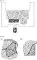
- the top portion of the fluid first meets the wall to prevent air in the bottom portion of the fluid from escaping, resulting in bubble formation (see FIG. 10 ).
- a pressure difference is created between the bubble and the fluid that form an interface therebetween and the corresponding pressure acts on the bubble from all directions.
- the pressure acting on the bubble is directed toward the surface of the structure.
- the edge may have a rounded corner.
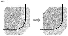
- the inclination of the bottom face increases gradually and the inclination of the fluid relative to the structure decreases gradually in a state in which the advancing contact angle between the advancing fluid and the bottom face is maintained ( FIG. 11 ).
- the angle of the fluid relative to the reference is calculated by subtracting 90° from the advancing contact angle of the fluid. The calculated angle is smaller than 90° and thus meets a condition where bubbles are not formed.
- the radius of the corner to avoid bubble formation should be larger than the size of bubbles formed when the edge is at a right angle.
- the edge has a radius of curvature of 0.1 to 1 mm and a height of 0.1 to 1 mm. That is, the corner is rounded with a radius of curvature of 0.1 to 1 mm to a height of 0.1 to 1 mm, as illustrated in FIGS. 10 and 11 . More preferably, the radius of curvature is 0.3 mm considering that it should be larger than that of bubbles when actually formed.
- the curvature of the rounded edge is less than the lower limit defined above, which is smaller than the minimum curvature of bubbles, bubbles are likely to be formed. Meanwhile, if the curvature of the rounded edge exceeds the upper limit defined above, the reduced bottom area offers only a small observable field of view.
- bubbles may be formed by the introduced second fluid.
- the antibiotic present in the second sub-well may remain partially undissolved in the bubbles, which may affect the analysis. It is therefore preferable that the lower end edge of the second sub-well is rounded similarly to that of the first sub-well.
- the use of the cell culture test device allows the dispensed fluids to be spread evenly over the entire well without bubble formation, enabling accurate imaging of changes in the growth of a target biological agent during antibiotic susceptibility testing using an optical microscope.
- the rapid cell culture test device of the present disclosure may be designed to be openable and closable through a fastening structure or may be provided with a cover film made of silicone, polyethylene terephthalate (PET), polyethylene (PE), polypropylene (PP), polystyrene (PS), polycarbonate (PC), Teflon or polyvinyl chloride (PVC).
- a cruciform or X-shaped punch may be formed at a position of the cover film corresponding to the underlying first sub-well 120. The punch can serve as an inlet portion through which a slight amount of the first fluid is easily introduced.
- a cruciform or X-shaped punch may be formed at a position of the cover film corresponding to the underlying second sub-well 130. The punch can serve as an inlet portion through which the second fluid is easily introduced. In terms of convenience of use, it is preferable that the shape of the inlet portion through which the first fluid is introduced is different from that of the inlet portion through which the second fluid is introduced.
- Focus marks may be provided on the underside of the cell culture test device 100 to provide information on the positions of the target.
- the focus marks may be marked on the underside of the cell culture test device 100 such that the target areas of the cell culture test device can be automatically tracked.
- the focus marks are provided in the form of microchannels by injection molding. Since the biological agent is immobilized in solid thin films, the use of the focus marks enables imaging of the same areas every time pictures are taken.
- the focus marks serve to correct the positions of the target in the three axial directions, i.e. x-, y-, and z-axis directions, in the automatic tracking of target areas.
- a cell analysis method using a cell culture test device having an array structure of a plurality of aligned well units, each of which includes an inlet portion through which a mixture solution of a gelling agent-containing liquid medium and a biological agent as a first fluid and a solvent selected from water, cell culture media, dimethylformamide (DMF), and dimethyl sulfoxide (DMSO) as a second fluid are introduced and a bottom portion including a first sub-well in which the first fluid is accommodated and a second sub-well in which the second fluid is accommodated and an antibiotic is loaded, wherein a first stepped portion protrudes toward the center of the well unit along the circumference of the inner wall of the well unit such that the well unit includes a lower portion whose inner width is smaller than that of an upper portion at the inlet portion side, the method including (a) introducing the first fluid into the first sub-well and gelling the mixture solution to form a solid thin film, (b) introducing the second fluid into
- a liquid medium containing a gelling agent is mixed with a biological agent to prepare a mixture solution as a first fluid.
- the liquid medium may include at least about 95% by weight of water and can be gelled due to the presence of the gelling agent.
- the gelling agent may be, for example, agar, agarose, gelatin, alginate, collagen or fibrin.
- agar or agarose is preferred.
- agar may be used in an amount of 0.3 to 4% by weight in the liquid medium.
- the liquid medium usually requires no nutrients. In some examples, however, the liquid medium may include nutrients.
- the liquid medium may be a solution including a medium stimulating the division of particular cells.
- suitable biological agents include viruses, bacteria, fungi, algae, protozoa, parasitic pathogens, human and mammalian cells, and biofilms.
- the biological agent may grow in a liquid or solid medium and the growth thereof may be affected by the kind and concentration of a foreign bioactive agent.
- the density of the biological agent in the mixture solution is from 10 2 to 10 10 cells/ml, preferably from 10 4 to 10 9 cells/ml, more preferably from 10 5 to 10 8 cells/ml. If the density of the biological agent is below the lower limit, it may be difficult to perceive the location of the biological agent. Meanwhile, if the density of the biological agent exceeds the upper limit, it may be difficult to perceive the individual state of the biological agent.
- the first fluid is supplied to each of the first sub-wells.
- the supplied first fluid may be evenly introduced into the first sub-well due to the curved shape of the inner edge and the second stepped portion, as described above.
- the first fluid can be supplied in an amount of 1 ⁇ l to 50 ⁇ l.
- the first fluid is gelled to form a solid thin film immobilized with the biological agent. When the temperature of the liquid medium drops, the medium is gelled, which restricts the mobility of the biological agent. This immobilization facilitates continuous observation of the motile biological agent.
- the thickness and width of the solid thin film are determined depending on the width of the first sub-well and the amount of the first fluid introduced.
- the term "thin film” refers to a thin layer that has a thickness sufficient to immobilize the biological agent and to observe single cells.
- the thickness of the thin film is typically in the range of 1 ⁇ m to 5 mm, 1 ⁇ m to 3 mm, 1 ⁇ m to 2 mm, 1 ⁇ m to 1.5 mm, 1 ⁇ m to 1 mm, 1 ⁇ m to 800 ⁇ m, 1 ⁇ m to 500 ⁇ m, 1 ⁇ m to 100 ⁇ m, 10 ⁇ m to 3 mm, 100 ⁇ m to 500 ⁇ m, 10 ⁇ m to 1 mm, 100 ⁇ m to 1 mm, 200 ⁇ m to 1 mm or 500 ⁇ m to 1 mm, but is not particularly limited to this range.
- the thickness of the solid thin film may correspond to the size of a side of the solid thin film in a direction perpendicular to a side of the solid thin film to be observed. Within the thickness range of the solid thin film defined above, the biological agent immobilized in the solid thin film can be observed on a single cell basis.
- a solvent selected from water, cell culture media, dimethylformamide (DMF), and dimethyl sulfoxide (DMSO) is supplied as a second fluid to the second sub-well 134.
- the second fluid is supplied to disperse or dissolve an antibiotic loaded in the second sub-well 134.
- the second fluid fills up the bottom portion 130 and the lower portion 112. Thereafter, the second fluid is continuously supplied to fill the well unit.
- the first stepped portion ensures uniform filling of the cell unit with the second fluid while avoiding concentration of the second fluid.
- the second fluid After filling the second sub-well, the second fluid is supplied to the first sub-well and comes into contact with the solid thin film of the first fluid. As a result, the antibiotic dispersed or dissolved in the second fluid may diffuse into the solid thin film.
- the biological agent immobilized in the solid thin film is distributed two-dimensionally, with the result that the biological agent can be observed on a single cell basis.
- changes in the growth of the individual cells can be typically observed within several tens of minutes (normally 30 minutes).
- the cell analysis method of the present disclosure allows for the determination of the influence of the antibiotic on the biological agent in a more accurate and rapid manner than conventional methods.
- the bioactivity of the antibiotic for bacterial cells can be tested within 3-4 hours. This rapid bioactivity test method is herein called single-cell morphological analysis (SCMA).
- SCMA single-cell morphological analysis
- the optical measurement system may include an imaging system, such as a CCD or CMOS camera.
- the optical measurement system may include optical units or devices necessary for focusing and light imaging, such as a lens, an illuminator, and a light guide.
- the optical measurement system may include an image processing system for processing and analyzing image data observed by the camera.
- the optical measurement system rapidly records and analyzes changes in the growth of the biological agent observed during testing to obtain test results.
- the area around the interface between the solid thin film of the first fluid and the second fluid is imaged.
- the imaging area may have a size of about 100 ⁇ m ⁇ 100 ⁇ m to 4000 ⁇ m ⁇ 4000 ⁇ m. It is preferable that the cross-sectional area of the first sub-well is at least larger in width than the imaging area.
- the use of the testing method based on the immobilization of the biological agent and the diffusion of the antibiotic can greatly reduce the amount of the drug and cells necessary for drug testing and enables rapid tracking of changes in the growth of single cells to obtain test results on the drug as rapidly as 2 hours (normally within 3-4 hours), compared to the prior art. This is the most rapid testing speed known thus far.
- the method may further include (d) observing changes of the biological agent responding to the antibiotic on a single cell basis to determine the minimum inhibitory concentration (MIC) or minimum biofilm eradication concentration (MBEC) of the antibiotic.
- MIC minimum inhibitory concentration
- MBEC minimum biofilm eradication concentration
- Biofilms are found in areas infected with microbes or to which microbes are attached.
- Biofilms refer to films that constitute mucilaginous microbial complexes, which are formed by microbes surrounded by polymer matrices.
- the formation of biofilms can greatly affect human health. Biofilms cause pulmonary infections, otitis media, periodontitis, and other infectious diseases.
- the resistance of bacteria present in biofilms to antibiotics is at least 1,000 times stronger than that of suspended bacteria.
- Flow cell systems and well-based systems have been used to investigate biofilms. However, these assay systems require a long time of several days for biofilm formation. Other difficulties associated with the use of the assay systems are that biofilms need to be stained and confocal microscopes should be used for observation. Further experiments are needed for the measurement of minimum inhibitory concentration (MIC) or minimum biofilm eradication concentration (MBEC). Such systems are very large in size and they fail to clearly show biofilm formation stages and to represent in vivo biofilm formation.
- the cell culture test device of the present disclosure proves to be an excellent alternative to conventional test devices.
- thermoplastic resin polystyrene
- FIGS. 1 and 2 A thermoplastic resin (polystyrene) was injection molded into the cell culture test device illustrated in FIGS. 1 and 2 , which had an array of 12 ⁇ 8 aligned well units.
- Example 1 The procedure of Example 1 was repeated except that the first stepped portions were omitted from the cell culture test device.
- Example 1 The procedure of Example 1 was repeated except that a portion of the side wall of each first sub-well lay in the same plane as the lower portion of the corresponding well unit.
- Example 1 The procedure of Example 1 was repeated except that the edges of the first sub-wells were at right angles.
- Example 1 and Comparative Examples 1-3 10 cell culture test devices having the same structure were manufactured (a total of 960 wells). A determination was made as to whether the first and second fluids were successfully introduced. Introduction success or failure of the fluids was judged based on bubble formation at the edges, imbalance of the second fluid, and leakage of the first fluid. The results are shown in Table 1.
- Table 1 Bubble generation at edges Imbalance of the second fluid Leakage of the first fluid
- Example 1 First fluid 0 - 4 Second fluid - 0 - Comparative Example 1
Landscapes
- Health & Medical Sciences (AREA)
- Chemical & Material Sciences (AREA)
- Life Sciences & Earth Sciences (AREA)
- Engineering & Computer Science (AREA)
- Organic Chemistry (AREA)
- Zoology (AREA)
- Wood Science & Technology (AREA)
- Bioinformatics & Cheminformatics (AREA)
- General Health & Medical Sciences (AREA)
- Biochemistry (AREA)
- Microbiology (AREA)
- Biotechnology (AREA)
- Genetics & Genomics (AREA)
- General Engineering & Computer Science (AREA)
- Biomedical Technology (AREA)
- Sustainable Development (AREA)
- Analytical Chemistry (AREA)
- Immunology (AREA)
- Molecular Biology (AREA)
- Proteomics, Peptides & Aminoacids (AREA)
- Clinical Laboratory Science (AREA)
- Cell Biology (AREA)
- Physics & Mathematics (AREA)
- Hematology (AREA)
- Toxicology (AREA)
- Biophysics (AREA)
- Urology & Nephrology (AREA)
- Chemical Kinetics & Catalysis (AREA)
- Food Science & Technology (AREA)
- Medicinal Chemistry (AREA)
- General Physics & Mathematics (AREA)
- Pathology (AREA)
- Apparatus Associated With Microorganisms And Enzymes (AREA)
Applications Claiming Priority (2)
| Application Number | Priority Date | Filing Date | Title |
|---|---|---|---|
| KR1020200028427A KR102145842B1 (ko) | 2020-03-06 | 2020-03-06 | 정확한 관찰이 용이한 신속한 세포배양검사 장치 |
| PCT/KR2020/013582 WO2021177530A1 (fr) | 2020-03-06 | 2020-10-06 | Dispositif d'inspection de culture cellulaire rapide facilitant une observation précise |
Publications (2)
| Publication Number | Publication Date |
|---|---|
| EP4006138A1 true EP4006138A1 (fr) | 2022-06-01 |
| EP4006138A4 EP4006138A4 (fr) | 2023-11-01 |
Family
ID=72291699
Family Applications (1)
| Application Number | Title | Priority Date | Filing Date |
|---|---|---|---|
| EP20923615.7A Pending EP4006138A4 (fr) | 2020-03-06 | 2020-10-06 | Dispositif d'inspection de culture cellulaire rapide facilitant une observation précise |
Country Status (4)
| Country | Link |
|---|---|
| US (1) | US20220333152A1 (fr) |
| EP (1) | EP4006138A4 (fr) |
| KR (1) | KR102145842B1 (fr) |
| WO (1) | WO2021177530A1 (fr) |
Families Citing this family (1)
| Publication number | Priority date | Publication date | Assignee | Title |
|---|---|---|---|---|
| KR102145842B1 (ko) * | 2020-03-06 | 2020-08-19 | 주식회사 퀀타매트릭스 | 정확한 관찰이 용이한 신속한 세포배양검사 장치 |
Family Cites Families (12)
| Publication number | Priority date | Publication date | Assignee | Title |
|---|---|---|---|---|
| US3957583A (en) * | 1974-12-02 | 1976-05-18 | Mcdonnell Douglas Corporation | Apparatus and process for determining the susceptibility of microorganisms to antibiotics |
| KR20130058954A (ko) * | 2011-11-28 | 2013-06-05 | 삼성전기주식회사 | 배양 용기 및 이의 시료 주입 방법 |
| KR101995767B1 (ko) * | 2013-01-11 | 2019-07-03 | 리제너론 파마슈티칼스 인코포레이티드 | 샘플 관리를 위한 시스템들 및 디바이스들 |
| WO2014178692A1 (fr) * | 2013-05-02 | 2014-11-06 | 주식회사 퀀타매트릭스 | Équipement d'essai de culture cellulaire à base de multiples puits microfluidiques |
| WO2015078884A1 (fr) * | 2013-11-26 | 2015-06-04 | Alleati Ag | Procédé et ensemble microfluidique pour test de sensibilité aux antibiotiques |
| JP6521432B2 (ja) * | 2015-03-26 | 2019-05-29 | 国立研究開発法人産業技術総合研究所 | 細胞培養器及び細胞培養方法 |
| US10023895B2 (en) | 2015-03-30 | 2018-07-17 | Accelerate Diagnostics, Inc. | Instrument and system for rapid microogranism identification and antimicrobial agent susceptibility testing |
| KR101718920B1 (ko) | 2015-06-30 | 2017-03-23 | (주) 마이크로핏 | 다각형 마이크로 플레이트, 이의 제조방법 및 이를 이용한 세포 집합체의 배양방법 |
| US20170191020A1 (en) * | 2015-12-30 | 2017-07-06 | Palo Alto Research Center Incorporated | Thermochromic sensing devices, systems, and methods |
| KR101711105B1 (ko) * | 2016-04-21 | 2017-03-06 | 주식회사 퀀타매트릭스 | 신속한 항생제 감수성 검사를 위한 멀티-웰 기반의 세포배양검사 장치 |
| JP2018143168A (ja) * | 2017-03-06 | 2018-09-20 | クアーズテック株式会社 | 細胞培養担体 |
| KR102145842B1 (ko) * | 2020-03-06 | 2020-08-19 | 주식회사 퀀타매트릭스 | 정확한 관찰이 용이한 신속한 세포배양검사 장치 |
-
2020
- 2020-03-06 KR KR1020200028427A patent/KR102145842B1/ko active Active
- 2020-10-06 EP EP20923615.7A patent/EP4006138A4/fr active Pending
- 2020-10-06 US US17/641,066 patent/US20220333152A1/en active Pending
- 2020-10-06 WO PCT/KR2020/013582 patent/WO2021177530A1/fr not_active Ceased
Also Published As
| Publication number | Publication date |
|---|---|
| EP4006138A4 (fr) | 2023-11-01 |
| KR102145842B1 (ko) | 2020-08-19 |
| US20220333152A1 (en) | 2022-10-20 |
| WO2021177530A1 (fr) | 2021-09-10 |
Similar Documents
| Publication | Publication Date | Title |
|---|---|---|
| US20250340922A1 (en) | Rapid cell culture test device capable of preventing gelled fluid from being detached | |
| CN105209595B (zh) | 微流体多孔型细胞培养测试装置 | |
| US11680241B2 (en) | Perfusion enabled bioreactors | |
| EP3434370B1 (fr) | Dispositif de test de culture cellulaire à puits multiples pour éprouver rapidement la sensibilité aux antibiotiques | |
| CN106399094A (zh) | 细胞培养和梯度迁移化验方法和装置 | |
| US12134780B2 (en) | Method for the culturing of cells | |
| EP2270573B1 (fr) | Couvercle de comptage, d'évaluation de viabilite, d'analyse et de manipulation | |
| EP4006138A1 (fr) | Dispositif d'inspection de culture cellulaire rapide facilitant une observation précise | |
| CN101218337A (zh) | 装置 | |
| EP4005673B1 (fr) | Dispositif de surveillance de culture cellulaire rapide comprenant une structure d'îlot | |
| US10606058B2 (en) | Microscope slide for liquid cultures | |
| US12297482B2 (en) | Rapid cell culture test device designed such that fluid films with uniform thickness are formed | |
| WO2021181337A1 (fr) | Puce microfluidique pour la culture à écoulement continu d'objets biologiques |
Legal Events
| Date | Code | Title | Description |
|---|---|---|---|
| STAA | Information on the status of an ep patent application or granted ep patent |
Free format text: STATUS: THE INTERNATIONAL PUBLICATION HAS BEEN MADE |
|
| PUAI | Public reference made under article 153(3) epc to a published international application that has entered the european phase |
Free format text: ORIGINAL CODE: 0009012 |
|
| STAA | Information on the status of an ep patent application or granted ep patent |
Free format text: STATUS: REQUEST FOR EXAMINATION WAS MADE |
|
| 17P | Request for examination filed |
Effective date: 20220225 |
|
| AK | Designated contracting states |
Kind code of ref document: A1 Designated state(s): AL AT BE BG CH CY CZ DE DK EE ES FI FR GB GR HR HU IE IS IT LI LT LU LV MC MK MT NL NO PL PT RO RS SE SI SK SM TR |
|
| DAV | Request for validation of the european patent (deleted) | ||
| DAX | Request for extension of the european patent (deleted) | ||
| A4 | Supplementary search report drawn up and despatched |
Effective date: 20231005 |
|
| RIC1 | Information provided on ipc code assigned before grant |
Ipc: B01L 3/00 20060101ALI20230928BHEP Ipc: C12M 1/00 20060101ALI20230928BHEP Ipc: C12Q 1/18 20060101ALI20230928BHEP Ipc: C12M 1/34 20060101ALI20230928BHEP Ipc: C12M 1/26 20060101ALI20230928BHEP Ipc: C12M 1/12 20060101ALI20230928BHEP Ipc: C12M 1/32 20060101AFI20230928BHEP |