EP4006180A1 - Hochfestes stahlblech für säureresistentes leitungsrohr, verfahren zur herstellung davon und mit hochfestem stahlblech hergestelltes leitungsrohr für säureresistentes stahlrohr - Google Patents
Hochfestes stahlblech für säureresistentes leitungsrohr, verfahren zur herstellung davon und mit hochfestem stahlblech hergestelltes leitungsrohr für säureresistentes stahlrohr Download PDFInfo
- Publication number
- EP4006180A1 EP4006180A1 EP20846097.2A EP20846097A EP4006180A1 EP 4006180 A1 EP4006180 A1 EP 4006180A1 EP 20846097 A EP20846097 A EP 20846097A EP 4006180 A1 EP4006180 A1 EP 4006180A1
- Authority
- EP
- European Patent Office
- Prior art keywords
- steel plate
- less
- temperature
- strength steel
- sour
- Prior art date
- Legal status (The legal status is an assumption and is not a legal conclusion. Google has not performed a legal analysis and makes no representation as to the accuracy of the status listed.)
- Pending
Links
Images
Classifications
-
- C—CHEMISTRY; METALLURGY
- C21—METALLURGY OF IRON
- C21D—MODIFYING THE PHYSICAL STRUCTURE OF FERROUS METALS; GENERAL DEVICES FOR HEAT TREATMENT OF FERROUS OR NON-FERROUS METALS OR ALLOYS; MAKING METAL MALLEABLE, e.g. BY DECARBURISATION OR TEMPERING
- C21D9/00—Heat treatment, e.g. annealing, hardening, quenching or tempering, adapted for particular articles; Furnaces therefor
- C21D9/46—Heat treatment, e.g. annealing, hardening, quenching or tempering, adapted for particular articles; Furnaces therefor for sheet metals
-
- B—PERFORMING OPERATIONS; TRANSPORTING
- B21—MECHANICAL METAL-WORKING WITHOUT ESSENTIALLY REMOVING MATERIAL; PUNCHING METAL
- B21C—MANUFACTURE OF METAL SHEETS, WIRE, RODS, TUBES, PROFILES OR LIKE SEMI-MANUFACTURED PRODUCTS OTHERWISE THAN BY ROLLING; AUXILIARY OPERATIONS USED IN CONNECTION WITH METAL-WORKING WITHOUT ESSENTIALLY REMOVING MATERIAL
- B21C37/00—Manufacture of metal sheets, rods, wire, tubes, profiles or like semi-manufactured products, not otherwise provided for; Manufacture of tubes of special shape
- B21C37/02—Manufacture of metal sheets, rods, wire, tubes, profiles or like semi-manufactured products, not otherwise provided for; Manufacture of tubes of special shape of sheets
-
- B—PERFORMING OPERATIONS; TRANSPORTING
- B21—MECHANICAL METAL-WORKING WITHOUT ESSENTIALLY REMOVING MATERIAL; PUNCHING METAL
- B21C—MANUFACTURE OF METAL SHEETS, WIRE, RODS, TUBES, PROFILES OR LIKE SEMI-MANUFACTURED PRODUCTS OTHERWISE THAN BY ROLLING; AUXILIARY OPERATIONS USED IN CONNECTION WITH METAL-WORKING WITHOUT ESSENTIALLY REMOVING MATERIAL
- B21C37/00—Manufacture of metal sheets, rods, wire, tubes, profiles or like semi-manufactured products, not otherwise provided for; Manufacture of tubes of special shape
- B21C37/06—Manufacture of metal sheets, rods, wire, tubes, profiles or like semi-manufactured products, not otherwise provided for; Manufacture of tubes of special shape of tubes or metal hoses; Combined procedures for making tubes, e.g. for making multi-wall tubes
-
- C—CHEMISTRY; METALLURGY
- C21—METALLURGY OF IRON
- C21D—MODIFYING THE PHYSICAL STRUCTURE OF FERROUS METALS; GENERAL DEVICES FOR HEAT TREATMENT OF FERROUS OR NON-FERROUS METALS OR ALLOYS; MAKING METAL MALLEABLE, e.g. BY DECARBURISATION OR TEMPERING
- C21D1/00—General methods or devices for heat treatment, e.g. annealing, hardening, quenching or tempering
- C21D1/02—Hardening articles or materials formed by forging or rolling, with no further heating beyond that required for the formation
-
- C—CHEMISTRY; METALLURGY
- C21—METALLURGY OF IRON
- C21D—MODIFYING THE PHYSICAL STRUCTURE OF FERROUS METALS; GENERAL DEVICES FOR HEAT TREATMENT OF FERROUS OR NON-FERROUS METALS OR ALLOYS; MAKING METAL MALLEABLE, e.g. BY DECARBURISATION OR TEMPERING
- C21D1/00—General methods or devices for heat treatment, e.g. annealing, hardening, quenching or tempering
- C21D1/18—Hardening; Quenching with or without subsequent tempering
- C21D1/19—Hardening; Quenching with or without subsequent tempering by interrupted quenching
- C21D1/20—Isothermal quenching, e.g. bainitic hardening
-
- C—CHEMISTRY; METALLURGY
- C21—METALLURGY OF IRON
- C21D—MODIFYING THE PHYSICAL STRUCTURE OF FERROUS METALS; GENERAL DEVICES FOR HEAT TREATMENT OF FERROUS OR NON-FERROUS METALS OR ALLOYS; MAKING METAL MALLEABLE, e.g. BY DECARBURISATION OR TEMPERING
- C21D6/00—Heat treatment of ferrous alloys
- C21D6/002—Heat treatment of ferrous alloys containing Cr
-
- C—CHEMISTRY; METALLURGY
- C21—METALLURGY OF IRON
- C21D—MODIFYING THE PHYSICAL STRUCTURE OF FERROUS METALS; GENERAL DEVICES FOR HEAT TREATMENT OF FERROUS OR NON-FERROUS METALS OR ALLOYS; MAKING METAL MALLEABLE, e.g. BY DECARBURISATION OR TEMPERING
- C21D6/00—Heat treatment of ferrous alloys
- C21D6/004—Heat treatment of ferrous alloys containing Cr and Ni
-
- C—CHEMISTRY; METALLURGY
- C21—METALLURGY OF IRON
- C21D—MODIFYING THE PHYSICAL STRUCTURE OF FERROUS METALS; GENERAL DEVICES FOR HEAT TREATMENT OF FERROUS OR NON-FERROUS METALS OR ALLOYS; MAKING METAL MALLEABLE, e.g. BY DECARBURISATION OR TEMPERING
- C21D6/00—Heat treatment of ferrous alloys
- C21D6/005—Heat treatment of ferrous alloys containing Mn
-
- C—CHEMISTRY; METALLURGY
- C21—METALLURGY OF IRON
- C21D—MODIFYING THE PHYSICAL STRUCTURE OF FERROUS METALS; GENERAL DEVICES FOR HEAT TREATMENT OF FERROUS OR NON-FERROUS METALS OR ALLOYS; MAKING METAL MALLEABLE, e.g. BY DECARBURISATION OR TEMPERING
- C21D7/00—Modifying the physical properties of iron or steel by deformation
- C21D7/02—Modifying the physical properties of iron or steel by deformation by cold working
- C21D7/10—Modifying the physical properties of iron or steel by deformation by cold working of the whole cross-section, e.g. of concrete reinforcing bars
- C21D7/12—Modifying the physical properties of iron or steel by deformation by cold working of the whole cross-section, e.g. of concrete reinforcing bars by expanding tubular bodies
-
- C—CHEMISTRY; METALLURGY
- C21—METALLURGY OF IRON
- C21D—MODIFYING THE PHYSICAL STRUCTURE OF FERROUS METALS; GENERAL DEVICES FOR HEAT TREATMENT OF FERROUS OR NON-FERROUS METALS OR ALLOYS; MAKING METAL MALLEABLE, e.g. BY DECARBURISATION OR TEMPERING
- C21D8/00—Modifying the physical properties of ferrous metals or ferrous alloys by deformation combined with, or followed by, heat treatment
- C21D8/02—Modifying the physical properties of ferrous metals or ferrous alloys by deformation combined with, or followed by, heat treatment during manufacturing of plates or strips
- C21D8/0221—Modifying the physical properties of ferrous metals or ferrous alloys by deformation combined with, or followed by, heat treatment during manufacturing of plates or strips characterised by the working steps
- C21D8/0226—Hot rolling
-
- C—CHEMISTRY; METALLURGY
- C21—METALLURGY OF IRON
- C21D—MODIFYING THE PHYSICAL STRUCTURE OF FERROUS METALS; GENERAL DEVICES FOR HEAT TREATMENT OF FERROUS OR NON-FERROUS METALS OR ALLOYS; MAKING METAL MALLEABLE, e.g. BY DECARBURISATION OR TEMPERING
- C21D8/00—Modifying the physical properties of ferrous metals or ferrous alloys by deformation combined with, or followed by, heat treatment
- C21D8/02—Modifying the physical properties of ferrous metals or ferrous alloys by deformation combined with, or followed by, heat treatment during manufacturing of plates or strips
- C21D8/0247—Modifying the physical properties of ferrous metals or ferrous alloys by deformation combined with, or followed by, heat treatment during manufacturing of plates or strips characterised by the heat treatment
- C21D8/0263—Modifying the physical properties of ferrous metals or ferrous alloys by deformation combined with, or followed by, heat treatment during manufacturing of plates or strips characterised by the heat treatment following hot rolling
-
- C—CHEMISTRY; METALLURGY
- C21—METALLURGY OF IRON
- C21D—MODIFYING THE PHYSICAL STRUCTURE OF FERROUS METALS; GENERAL DEVICES FOR HEAT TREATMENT OF FERROUS OR NON-FERROUS METALS OR ALLOYS; MAKING METAL MALLEABLE, e.g. BY DECARBURISATION OR TEMPERING
- C21D8/00—Modifying the physical properties of ferrous metals or ferrous alloys by deformation combined with, or followed by, heat treatment
- C21D8/10—Modifying the physical properties of ferrous metals or ferrous alloys by deformation combined with, or followed by, heat treatment during manufacturing of tubular bodies
-
- C—CHEMISTRY; METALLURGY
- C21—METALLURGY OF IRON
- C21D—MODIFYING THE PHYSICAL STRUCTURE OF FERROUS METALS; GENERAL DEVICES FOR HEAT TREATMENT OF FERROUS OR NON-FERROUS METALS OR ALLOYS; MAKING METAL MALLEABLE, e.g. BY DECARBURISATION OR TEMPERING
- C21D9/00—Heat treatment, e.g. annealing, hardening, quenching or tempering, adapted for particular articles; Furnaces therefor
- C21D9/08—Heat treatment, e.g. annealing, hardening, quenching or tempering, adapted for particular articles; Furnaces therefor for tubular bodies or pipes
-
- C—CHEMISTRY; METALLURGY
- C22—METALLURGY; FERROUS OR NON-FERROUS ALLOYS; TREATMENT OF ALLOYS OR NON-FERROUS METALS
- C22C—ALLOYS
- C22C38/00—Ferrous alloys, e.g. steel alloys
- C22C38/001—Ferrous alloys, e.g. steel alloys containing N
-
- C—CHEMISTRY; METALLURGY
- C22—METALLURGY; FERROUS OR NON-FERROUS ALLOYS; TREATMENT OF ALLOYS OR NON-FERROUS METALS
- C22C—ALLOYS
- C22C38/00—Ferrous alloys, e.g. steel alloys
- C22C38/002—Ferrous alloys, e.g. steel alloys containing In, Mg, or other elements not provided for in one single group C22C38/001 - C22C38/60
-
- C—CHEMISTRY; METALLURGY
- C22—METALLURGY; FERROUS OR NON-FERROUS ALLOYS; TREATMENT OF ALLOYS OR NON-FERROUS METALS
- C22C—ALLOYS
- C22C38/00—Ferrous alloys, e.g. steel alloys
- C22C38/005—Ferrous alloys, e.g. steel alloys containing rare earths, i.e. Sc, Y, Lanthanides
-
- C—CHEMISTRY; METALLURGY
- C22—METALLURGY; FERROUS OR NON-FERROUS ALLOYS; TREATMENT OF ALLOYS OR NON-FERROUS METALS
- C22C—ALLOYS
- C22C38/00—Ferrous alloys, e.g. steel alloys
- C22C38/02—Ferrous alloys, e.g. steel alloys containing silicon
-
- C—CHEMISTRY; METALLURGY
- C22—METALLURGY; FERROUS OR NON-FERROUS ALLOYS; TREATMENT OF ALLOYS OR NON-FERROUS METALS
- C22C—ALLOYS
- C22C38/00—Ferrous alloys, e.g. steel alloys
- C22C38/04—Ferrous alloys, e.g. steel alloys containing manganese
-
- C—CHEMISTRY; METALLURGY
- C22—METALLURGY; FERROUS OR NON-FERROUS ALLOYS; TREATMENT OF ALLOYS OR NON-FERROUS METALS
- C22C—ALLOYS
- C22C38/00—Ferrous alloys, e.g. steel alloys
- C22C38/06—Ferrous alloys, e.g. steel alloys containing aluminium
-
- C—CHEMISTRY; METALLURGY
- C22—METALLURGY; FERROUS OR NON-FERROUS ALLOYS; TREATMENT OF ALLOYS OR NON-FERROUS METALS
- C22C—ALLOYS
- C22C38/00—Ferrous alloys, e.g. steel alloys
- C22C38/08—Ferrous alloys, e.g. steel alloys containing nickel
-
- C—CHEMISTRY; METALLURGY
- C22—METALLURGY; FERROUS OR NON-FERROUS ALLOYS; TREATMENT OF ALLOYS OR NON-FERROUS METALS
- C22C—ALLOYS
- C22C38/00—Ferrous alloys, e.g. steel alloys
- C22C38/12—Ferrous alloys, e.g. steel alloys containing tungsten, tantalum, molybdenum, vanadium, or niobium
-
- C—CHEMISTRY; METALLURGY
- C22—METALLURGY; FERROUS OR NON-FERROUS ALLOYS; TREATMENT OF ALLOYS OR NON-FERROUS METALS
- C22C—ALLOYS
- C22C38/00—Ferrous alloys, e.g. steel alloys
- C22C38/14—Ferrous alloys, e.g. steel alloys containing titanium or zirconium
-
- C—CHEMISTRY; METALLURGY
- C22—METALLURGY; FERROUS OR NON-FERROUS ALLOYS; TREATMENT OF ALLOYS OR NON-FERROUS METALS
- C22C—ALLOYS
- C22C38/00—Ferrous alloys, e.g. steel alloys
- C22C38/16—Ferrous alloys, e.g. steel alloys containing copper
-
- C—CHEMISTRY; METALLURGY
- C22—METALLURGY; FERROUS OR NON-FERROUS ALLOYS; TREATMENT OF ALLOYS OR NON-FERROUS METALS
- C22C—ALLOYS
- C22C38/00—Ferrous alloys, e.g. steel alloys
- C22C38/18—Ferrous alloys, e.g. steel alloys containing chromium
- C22C38/22—Ferrous alloys, e.g. steel alloys containing chromium with molybdenum or tungsten
-
- C—CHEMISTRY; METALLURGY
- C22—METALLURGY; FERROUS OR NON-FERROUS ALLOYS; TREATMENT OF ALLOYS OR NON-FERROUS METALS
- C22C—ALLOYS
- C22C38/00—Ferrous alloys, e.g. steel alloys
- C22C38/18—Ferrous alloys, e.g. steel alloys containing chromium
- C22C38/24—Ferrous alloys, e.g. steel alloys containing chromium with vanadium
-
- C—CHEMISTRY; METALLURGY
- C22—METALLURGY; FERROUS OR NON-FERROUS ALLOYS; TREATMENT OF ALLOYS OR NON-FERROUS METALS
- C22C—ALLOYS
- C22C38/00—Ferrous alloys, e.g. steel alloys
- C22C38/18—Ferrous alloys, e.g. steel alloys containing chromium
- C22C38/26—Ferrous alloys, e.g. steel alloys containing chromium with niobium or tantalum
-
- C—CHEMISTRY; METALLURGY
- C22—METALLURGY; FERROUS OR NON-FERROUS ALLOYS; TREATMENT OF ALLOYS OR NON-FERROUS METALS
- C22C—ALLOYS
- C22C38/00—Ferrous alloys, e.g. steel alloys
- C22C38/18—Ferrous alloys, e.g. steel alloys containing chromium
- C22C38/28—Ferrous alloys, e.g. steel alloys containing chromium with titanium or zirconium
-
- C—CHEMISTRY; METALLURGY
- C22—METALLURGY; FERROUS OR NON-FERROUS ALLOYS; TREATMENT OF ALLOYS OR NON-FERROUS METALS
- C22C—ALLOYS
- C22C38/00—Ferrous alloys, e.g. steel alloys
- C22C38/18—Ferrous alloys, e.g. steel alloys containing chromium
- C22C38/38—Ferrous alloys, e.g. steel alloys containing chromium with more than 1.5% by weight of manganese
-
- C—CHEMISTRY; METALLURGY
- C22—METALLURGY; FERROUS OR NON-FERROUS ALLOYS; TREATMENT OF ALLOYS OR NON-FERROUS METALS
- C22C—ALLOYS
- C22C38/00—Ferrous alloys, e.g. steel alloys
- C22C38/18—Ferrous alloys, e.g. steel alloys containing chromium
- C22C38/40—Ferrous alloys, e.g. steel alloys containing chromium with nickel
- C22C38/42—Ferrous alloys, e.g. steel alloys containing chromium with nickel with copper
-
- C—CHEMISTRY; METALLURGY
- C22—METALLURGY; FERROUS OR NON-FERROUS ALLOYS; TREATMENT OF ALLOYS OR NON-FERROUS METALS
- C22C—ALLOYS
- C22C38/00—Ferrous alloys, e.g. steel alloys
- C22C38/18—Ferrous alloys, e.g. steel alloys containing chromium
- C22C38/40—Ferrous alloys, e.g. steel alloys containing chromium with nickel
- C22C38/44—Ferrous alloys, e.g. steel alloys containing chromium with nickel with molybdenum or tungsten
-
- C—CHEMISTRY; METALLURGY
- C22—METALLURGY; FERROUS OR NON-FERROUS ALLOYS; TREATMENT OF ALLOYS OR NON-FERROUS METALS
- C22C—ALLOYS
- C22C38/00—Ferrous alloys, e.g. steel alloys
- C22C38/18—Ferrous alloys, e.g. steel alloys containing chromium
- C22C38/40—Ferrous alloys, e.g. steel alloys containing chromium with nickel
- C22C38/46—Ferrous alloys, e.g. steel alloys containing chromium with nickel with vanadium
-
- C—CHEMISTRY; METALLURGY
- C22—METALLURGY; FERROUS OR NON-FERROUS ALLOYS; TREATMENT OF ALLOYS OR NON-FERROUS METALS
- C22C—ALLOYS
- C22C38/00—Ferrous alloys, e.g. steel alloys
- C22C38/18—Ferrous alloys, e.g. steel alloys containing chromium
- C22C38/40—Ferrous alloys, e.g. steel alloys containing chromium with nickel
- C22C38/48—Ferrous alloys, e.g. steel alloys containing chromium with nickel with niobium or tantalum
-
- C—CHEMISTRY; METALLURGY
- C22—METALLURGY; FERROUS OR NON-FERROUS ALLOYS; TREATMENT OF ALLOYS OR NON-FERROUS METALS
- C22C—ALLOYS
- C22C38/00—Ferrous alloys, e.g. steel alloys
- C22C38/18—Ferrous alloys, e.g. steel alloys containing chromium
- C22C38/40—Ferrous alloys, e.g. steel alloys containing chromium with nickel
- C22C38/50—Ferrous alloys, e.g. steel alloys containing chromium with nickel with titanium or zirconium
-
- C—CHEMISTRY; METALLURGY
- C22—METALLURGY; FERROUS OR NON-FERROUS ALLOYS; TREATMENT OF ALLOYS OR NON-FERROUS METALS
- C22C—ALLOYS
- C22C38/00—Ferrous alloys, e.g. steel alloys
- C22C38/18—Ferrous alloys, e.g. steel alloys containing chromium
- C22C38/40—Ferrous alloys, e.g. steel alloys containing chromium with nickel
- C22C38/58—Ferrous alloys, e.g. steel alloys containing chromium with nickel with more than 1.5% by weight of manganese
-
- F—MECHANICAL ENGINEERING; LIGHTING; HEATING; WEAPONS; BLASTING
- F16—ENGINEERING ELEMENTS AND UNITS; GENERAL MEASURES FOR PRODUCING AND MAINTAINING EFFECTIVE FUNCTIONING OF MACHINES OR INSTALLATIONS; THERMAL INSULATION IN GENERAL
- F16L—PIPES; JOINTS OR FITTINGS FOR PIPES; SUPPORTS FOR PIPES, CABLES OR PROTECTIVE TUBING; MEANS FOR THERMAL INSULATION IN GENERAL
- F16L9/00—Rigid pipes
- F16L9/02—Rigid pipes of metal
-
- C—CHEMISTRY; METALLURGY
- C21—METALLURGY OF IRON
- C21D—MODIFYING THE PHYSICAL STRUCTURE OF FERROUS METALS; GENERAL DEVICES FOR HEAT TREATMENT OF FERROUS OR NON-FERROUS METALS OR ALLOYS; MAKING METAL MALLEABLE, e.g. BY DECARBURISATION OR TEMPERING
- C21D2201/00—Treatment for obtaining particular effects
- C21D2201/05—Grain orientation
-
- C—CHEMISTRY; METALLURGY
- C21—METALLURGY OF IRON
- C21D—MODIFYING THE PHYSICAL STRUCTURE OF FERROUS METALS; GENERAL DEVICES FOR HEAT TREATMENT OF FERROUS OR NON-FERROUS METALS OR ALLOYS; MAKING METAL MALLEABLE, e.g. BY DECARBURISATION OR TEMPERING
- C21D2211/00—Microstructure comprising significant phases
- C21D2211/002—Bainite
Definitions
- the present disclosure relates to a high strength steel plate for a sour-resistant line pipe having excellent steel plate material homogeneity and suitable for use in a line pipe used for transportation of crude oil or natural gas, and a production method therefor.
- the present disclosure also relates to a high strength steel pipe using the high strength steel plate for a sour-resistant line pipe.
- a line pipe is typically produced by forming a steel plate produced by a plate mill or a hot rolling mill into a steel pipe by UOE forming, press bend forming, roll forming, or the like.
- HIC hydrogen induced cracking
- SSCC sulfide stress corrosion cracking
- SSCC is known to occur in high hardness regions of welds, and normally has not been regarded as a significant problem in high strength seamless steel pipes for oil wells or line pipes having relatively low hardness.
- mining environments for crude oil and natural gas have become increasingly severe, and it has been reported that SSCC occurs in base metal portions of line pipes in environments with high hydrogen sulfide partial pressure or low pH. This has raised the importance of controlling the hardness of the surface layer of the inner surface of a steel pipe and improving the SSCC resistance in severer corrosion environments.
- microcracking called fissure may occur in environments with relatively low hydrogen sulfide partial pressure.
- SSCC is likely to occur in this case, too.
- thermo-mechanical control process TMCP
- TMCP thermo-mechanical control process
- An effective way of enhancing the strength of steel material using the TMCP technology is to increase the cooling rate in controlled cooling.
- controlled cooling is performed at a high cooling rate, however, the surface layer of the steel plate is cooled rapidly, and consequently increases in hardness as compared with the inside of the steel plate. Further, strain hardening is induced when forming the steel plate into a pipe, as a result of which the hardness of the surface layer increases and the SSCC resistance decreases.
- JP 6369658 B2 proposes a technique of performing multistage cooling after hot rolling to limit the maximum hardness in the region from the surface of a steel pipe to 1.0 mm in depth to 250 Hv or less.
- JP 2011-017048 A proposes performing low-temperature heat treatment to limit the hardness of a steel pipe to 220 Hv or less and increase the HIC resistance.
- the technique described in PTL 1 can improve the SSCC resistance in environments containing hydrogen sulfide with a partial pressure of more than 0.1 MPa (1 bar), but does not address SSCC caused by microcracking called fissure in environments with low hydrogen sulfide partial pressure.
- the technique described in PTL 2 does not provide a means of improving the SSCC resistance in environments with high hydrogen sulfide partial pressure, unlike the HIC resistance which is evaluated in an NACE test performed with hydrogen sulfide gas being saturated in a solution.
- a high strength steel plate for a sour-resistant line pipe and a high strength steel pipe using the high strength steel plate for a sour-resistant line pipe according to the present disclosure are excellent not only in HIC resistance but also in SSCC resistance in environments containing hydrogen sulfide with a partial pressure of more than 1 bar and in SSCC resistance in environments with a low hydrogen sulfide partial pressure of 1 bar or less.
- a production method for a high strength steel plate for a sour-resistant line pipe can produce a high strength steel plate for a sour-resistant line pipe excellent not only in HIC resistance but also in SSCC resistance in environments containing hydrogen sulfide with a partial pressure of more than 1 bar and in SSCC resistance in environments with a low hydrogen sulfide partial pressure of 1 bar or less.
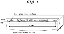
- FIG. 1 is a schematic diagram explaining a method of collecting a test piece for evaluation of SSCC resistance in examples.
- a high strength steel plate for a sour-resistant line pipe according to the present disclosure will be described in detail below.
- the C content effectively contributes to improved strength. If the C content is less than 0.020 %, sufficient strength cannot be ensured. The C content is therefore 0.020 % or more, and preferably 0.025 % or more. If the C content is more than 0.080 %, the hardness of the surface layer or the central segregation area increases during accelerated cooling, causing degradation in SSCC resistance and HIC resistance. The toughness is degraded, too. The C content is therefore 0.080 % or less, and preferably 0.070 % or less.
- Si is added for deoxidation. If the Si content is less than 0.01 %, the deoxidation effect is insufficient. The Si content is therefore 0.01 % or more, and preferably 0.05 % or more. If the Si content is more than 0.50 %, the toughness and the weldability are degraded. The Si content is therefore 0.50 % or less, and preferably 0.45 % or less.
- Mn effectively contributes to improved strength and toughness. If the Mn content is less than 0.50 %, the effect is insufficient. The Mn content is therefore 0.50 % or more, and preferably 0.80 % or more. If the Mn content is more than 1.80 %, the hardness of the surface layer or the central segregation area increases during accelerated cooling, causing degradation in SSCC resistance and HIC resistance. The weldability is degraded, too. The Mn content is therefore 1.80 %, and preferably 1.70 % or less.
- P is an inevitable impurity element. P degrades the weldability, and also increases the hardness of the surface layer or the central segregation area, thus causing degradation in SSCC resistance and HIC resistance. This tendency is noticeable when the P content is more than 0.015 %. Accordingly, the upper limit is 0.015 %.
- the P content is preferably 0.008 % or less. Although the P content is desirably as low as possible, the P content is preferably 0.001 % or more from the viewpoint of the refining costs.
- S is an inevitable impurity element. Since S forms a MnS inclusion in the steel and degrades the HIC resistance, the S content is desirably low, but up to 0.0015 % is allowable. The S content is preferably 0.0010 % or less. Although the S content is desirably as low as possible, the S content is preferably 0.0002 % or more from the viewpoint of the refining costs.
- Al is added as a deoxidizer. If the Al content is less than 0.010 %, the effect is insufficient. The Al content is therefore 0.010 % or more, and preferably 0.015 % or more. If the Al content is more than 0.080 %, the cleanliness of the steel decreases, and the toughness is degraded. The Al content is therefore 0.080 % or less, and preferably 0.070 % or less.
- N effectively contributes to improved strength. If the N content is less than 0.0010 %, sufficient strength cannot be ensured. The N content is therefore 0.0010 % or more, and preferably 0.0015 % or more. If the N content is more than 0.0080 %, the hardness of the surface layer or the central segregation area increases during accelerated cooling, causing degradation in SSCC resistance and HIC resistance. The toughness is degraded, too. The N content is therefore 0.0080 % or less, and preferably 0.0070 % or less.
- Mo is an element effective in improving the toughness and increasing the strength, and effective in improving the SSCC resistance regardless of the hydrogen sulfide partial pressure.
- the Mo content is therefore 0.50 % or less, and preferably 0.40 % or less.
- Ca is an element effective in improving the HIC resistance by morphological control of sulfide inclusions. If the Ca content is less than 0.0005 %, the effect by addition of Ca is insufficient. The Ca content is therefore 0.0005 % or more, and preferably 0.0008 % or more. If the Ca content is more than 0.0050 %, not only the effect is saturated, but also the cleanliness of the steel decreases, causing degradation in HIC resistance. The Ca content is therefore 0.0050 %, and preferably 0.0045 % or less.
- the chemical composition according to the present disclosure may optionally contain one or more selected from the group consisting of Cu, Ni, and Cr in the following ranges for further improvement in the strength and toughness of the steel plate.
- the Cu is an element effective in improving the toughness and increasing the strength.
- the Cu content is preferably 0.05 % or more. If the Cu content is more than 0.30 %, microcracking called fissure tends to occur in environments with a low hydrogen sulfide partial pressure of less than 1 bar. Accordingly, in the case of adding Cu, the upper limit is 0.30 %.
- the Cu content is preferably 0.25 % or less.
- Ni is an element effective in improving the toughness and increasing the strength.
- the Ni content is preferably 0.01 % or more. If the Ni content is more than 0.10 %, microcracking called fissure tends to occur in environments with a low hydrogen sulfide partial pressure of less than 1 bar. Accordingly, in the case of adding Ni, the upper limit is 0.10 %.
- the Ni content is preferably 0.02 % or less.
- the Cr content is an element effective in obtaining sufficient strength even when the C content is low, as with Mn.
- the Cr content is preferably 0.05 % or more. If the Cr content is excessively high, the hardenability is excessively high. As a result, the hardness of the surface layer or the central segregation area increases during accelerated cooling, causing degradation in SSCC resistance. The weldability is degraded, too. Accordingly, in the case of adding Cr, the upper limit is 0.50 %.
- the Cr content is preferably 0.45 % or less.
- the chemical composition according to the present disclosure may optionally further contain one or more selected from the group consisting of Nb, V, Ti, Zr, Mg, and REM in the following ranges.
- Nb 0.005 % to 0.1 %
- V 0.005 % to 0.1 %
- Ti 0.005 % to 0.1 %
- Zr 0.0005 % to 0.02 %
- Mg 0.0005 % to 0.02 %
- REM 0.0005 % to 0.02 %
- Nb, V, and Ti are each an element that may be optionally added in order to enhance the strength and toughness of the steel plate. If the content of each of these elements is less than 0.005 %, the effect is insufficient. Accordingly, in the case of adding any of these elements, the content is preferably 0.005 % or more. If the content of each of these elements is more than 0.1 %, the toughness of the weld is degraded. Accordingly, in the case of adding any of these elements, the content is preferably 0.1 % or less.
- Zr, Mg, and REM are each an element that may be optionally added in order to enhance the toughness through crystal grain refinement and/or enhance the cracking resistance through control of inclusion characteristics. If the content of each of these elements is less than 0.0005 %, the effect is insufficient. Accordingly, in the case of adding any of these elements, the content is preferably 0.0005 % or more. If the content of each of these elements is more than 0.02 %, the effect is saturated. Accordingly, in the case of adding any of these elements, the content is preferably 0.02 % or less.
- a CP value calculated according to the following Formula (1) is preferably 1.00 or less. In the formula, 0 is assigned for each element not added.
- CP 4.46 % C + 2.37 % Mn / 6 + 1.74 % Cu + 1.7 % Ni / 15 + 1.18 % Cr + 1.95 % Mo + 1.74 % V / 5 + 22.36 % P
- [%X] denotes the content (mass%) of element X in the steel.
- the formula for calculating the CP value is designed to estimate the material property of the central segregation area from the content of each alloying element.
- the CP value calculated according to Formula (1) is higher, the component concentration in the central segregation area is higher, and the hardness of the central segregation area increases.
- the CP value according to Formula (1) is lower, the hardness of the central segregation area is lower.
- the upper limit of the CP value may be 0.95.
- the balance other than the elements described above consists of Fe and inevitable impurities.
- the inclusion of other trace elements is tolerable as long as the effects according to the present disclosure are not undermined.
- O is an element inevitably contained in steel.
- a O content of 0.0050 % or less is allowable.
- the O content is preferably 0.0040 % or less.
- the steel microstructure at 0.25 mm below the surface of the steel plate needs to be bainitic microstructure, in order to reduce the maximum hardness at 0.25 mm below the surface of the steel plate to not greater than a certain level and improve the SSCC resistance.
- the whole steel microstructure is bainitic microstructure, in order to achieve high strength of 520 MPa or more in tensile strength.
- hard phase such as martensite or martensite austenite constituent (MA) forms in the surface layer
- the hardness of the surface layer increases, and variations in hardness in the steel plate increase, which impairs the material homogeneity.
- the steel microstructure of the surface layer is bainitic microstructure.
- the bainitic microstructure includes a microstructure called bainitic ferrite or granular ferrite generated as a result of transformation during or after accelerated cooling and contributing to transformation strengthening. If any other microstructure such as ferrite, martensite, pearlite, martensite austenite constituent, or retained austenite is mixed in the bainitic microstructure, the strength decreases, the toughness is degraded, and the hardness of the surface layer increases. Hence, the proportion of microstructure other than bainitic phase is desirably as low as possible. However, in the case where the volume fraction of microstructure other than bainitic phase is sufficiently low, the influence of such microstructure is negligible.
- microstructure other than bainitic phase is allowable.
- 5 % or less in terms of the total volume fraction of steel microstructures other than bainite is allowable as their influence is negligible.
- bainitic microstructure there are various forms of bainitic microstructure depending on the cooling rate.
- the microstructure of the outermost surface layer of the steel plate specifically the steel microstructure at 0.25 mm below the surface of the steel plate, is bainitic microstructure and the area ratio of crystal grains having a KAM value of 0.4 or more in the bainite is 50 % or less.
- a KAM value reflects a local crystal orientation change due to a dislocation in microstructure.
- a higher KAM value indicates that the degree of local deformation in a grain is higher.
- high transformation strain is introduced in bainitic microstructure, meaning the grain is low-temperature transformation phase.
- low-temperature transformation phase is hard microstructure, if the proportion of low-temperature transformation phase is high, the SSCC resistance is degraded.
- crystal grains having a KAM value of 0.4 or more are low-temperature transformation phase, and thus have high hardness. If the proportion of crystal grains having a KAM value of 0.4 or more is more than 50 %, cracks propagate easily, so that the SSCC resistance is degraded significantly. Accordingly, the area ratio of crystal grains having a KAM value of 0.4 or more in the bainite needs to be 50 % or less.
- the outermost surface layer from the surface of the steel plate to 0.25 mm in depth has the same steel microstructure, as a result of which the SSCC resistance improving effect can be achieved.
- the steel microstructure at 0.25 mm below the surface of the steel plate to bainitic microstructure By limiting the steel microstructure at 0.25 mm below the surface of the steel plate to bainitic microstructure, limiting the area ratio of crystal grains having a KAM value of 0.4 or more in the bainite to 50 % or less, and further limiting the maximum hardness of HV 0.1 at 0.25 mm below the surface to 230 or less, the SSCC resistance of a pipe after pipe formation from the steel plate can be ensured.
- the high strength steel plate according to the present disclosure is a steel plate for a steel pipe having a strength greater than or equal to API 5L grade X60, and accordingly has a tensile strength of 520 MPa or more.
- the production method according to the present disclosure includes heating a slab having the above-described chemical composition, thereafter hot rolling the slab to obtain a steel plate, and thereafter subjecting the steel plate to controlled cooling under predetermined conditions.
- the slab heating temperature is less than 1000 °C, the dissolution of carbides is insufficient, and the degree of solid solution strengthening is low, so that the required strength cannot be obtained. If the slab heating temperature is more than 1300 °C, crystal grains coarsen extremely, and the toughness is degraded.
- the slab heating temperature is therefore 1000 °C to 1300 °C.
- the slab heating temperature is preferably 1030 °C to 1250 °C. The slab is heated to its center to this temperature.
- the rolling finish temperature is desirably as low as possible in order to obtain high base metal toughness. If the rolling finish temperature is low, however, the rolling efficiency decreases. Hence, the rolling finish temperature at the surface of the steel plate needs to be set in consideration of the required base metal toughness and the rolling efficiency.
- the rolling finish temperature is preferably Ar 3 transformation point or more in terms of the surface temperature of the steel plate.
- the Ar 3 transformation point denotes ferrite transformation start temperature during cooling, and can be calculated, for example, from the components of the steel using the following formula.
- the surface temperature of the steel plate can be measured using a radiation thermometer or the like.
- Ar 3 ° C 910 ⁇ 310 % C ⁇ 80 % Mn ⁇ 20 % Cu ⁇ 15 % Cr ⁇ 55 % Ni ⁇ 80 % Mo
- [%X] denotes the content (mass%) of element X in the steel.
- Cooling start temperature (Ar 3 - 10) °C or more in terms of surface temperature of steel plate
- the surface temperature of the steel plate at the cooling start is low, the amount of ferrite formed before the controlled cooling increases.
- the surface temperature of the steel plate at the cooling start is (Ar 3 - 10) °C or more.
- Average cooling rate from 750 °C to 550 °C at 0.25 mm below surface of steel plate 20 °C/s to 50 °C/s
- the average cooling rate is important to lower the average cooling rate from 750 °C to 550 °C in terms of a temperature at 0.25 mm below the surface of the steel plate as much as possible to form high-temperature transformation phase.
- a lower cooling rate contributes to lower maximum hardness. Since the temperature range from 750 °C to 550 °C is a crucial temperature range in bainite transformation, it is important to control the cooling rate in this temperature range. If the cooling rate is more than 50 °C/s, the proportion of low-temperature transformation phase is high, and the maximum hardness of HV 0.5 at 0.25 mm below the surface of the steel plate is more than 230, so that the SSCC resistance after pipe formation is degraded. The average cooling rate is therefore 50 °C/s or less.
- the average cooling rate is preferably 30 °C/s or less. Although no lower limit is placed on the average cooling rate, if the cooling rate is excessively low, ferrite and pearlite form, causing insufficient strength. To prevent this, the average cooling rate is preferably 20 °C/s or more. Regarding cooling from 550 °C in terms of a temperature at 0.25 mm below the surface of the steel plate, if the cooling rate is low, there is a possibility that cooling cannot be performed in a stable nucleate boiling state, and the hardness varies in the outermost surface layer of the steel plate and the maximum value of Vickers hardness increases. Accordingly, the average cooling rate from 550 °C to the cooling stop temperature in terms of a temperature at 0.25 mm below the surface of the steel plate is preferably 150 °C/s or more.
- Average cooling rate from 750 °C to 550 °C in terms of average temperature of steel plate 15 °C/s or more
- the cooling rate in terms of the average temperature of the steel plate is 15 °C/s or more.
- the cooling rate in terms of the average temperature of the steel plate is preferably 20 °C/s or more.
- the average cooling rate is preferably 40 °C/s or less to prevent excessive formation of low-temperature transformation phase.
- the temperature at 0.25 mm below the surface of the steel plate and the average temperature of the steel plate cannot be physically measured directly, but can be determined in real time, for example, from the result of calculating the temperature distribution in a section along the plate thickness by difference calculation using a process computer based on the surface temperature at the cooling start measured with a radiation thermometer and the target surface temperature at the cooling stop.
- the temperature at 0.25 mm below the surface of the steel plate in the temperature distribution is referred to as "temperature at 0.25 mm below the surface of the steel plate”
- the average temperature in the plate thickness direction in the temperature distribution is referred to as "average temperature of the steel plate”.
- Cooling stop temperature 250 °C to 550 °C in terms of temperature at 0.25 mm below surface of steel plate
- cooling stop temperature is more than 550 °C, bainite transformation is incomplete, and sufficient strength cannot be obtained. If the cooling stop temperature is less than 250 °C, the dislocation density is high, and the hardness of the surface layer after pipe formation increases considerably, causing degradation in SSCC resistance.
- a high strength steel pipe (UOE steel pipe, electric resistance welded steel pipe, spiral steel pipe, etc.) for a sour-resistant line pipe having excellent steel plate material homogeneity and suitable for transportation of crude oil or natural gas can be produced.
- the steel pipe produced using the high strength steel plate according to the present disclosure has excellent SSCC resistance even in the case where there is a high hardness region of a weld.
- a UOE steel pipe is produced by milling and beveling the edges of a steel plate, forming the steel plate into a steel pipe shape by C press, U-ing press, and O-ing press, then seam welding the butting portions by inside welding and outside welding, and optionally subjecting it to pipe expansion.
- Any welding method may be used as long as sufficient joint strength and joint toughness are ensured, yet it is preferable to use submerged arc welding from the viewpoint of excellent weld quality and production efficiency.
- a steel pipe produced by forming a steel plate into a pipe shape by press bend forming and then seam welding the butting portions may be subjected to pipe expansion, too.
- Steels having the chemical compositions listed in Table 1 were prepared and subjected to continuous casting to obtain slabs. Each slab thus obtained was heated to the temperature listed in Table 2, and then hot rolled with the rolling finish temperature listed in Table 2, to obtain a steel plate with the plate thickness listed in Table 2. Each steel plate was then subjected to controlled cooling using a water cooling type controlled cooling device under the conditions listed in Table 2. After this, the edges of the steel plate were milled and beveled, and the steel plate was formed into a steel pipe shape by C press, U-ing press, and O-ing press. Subsequently, the butting portions of the inner surface and the outer surface were seam welded by submerged arc welding, and pipe expansion was performed to obtain a steel pipe.
- Table 1 steel sample IDs A to W
- each steel plate obtained as described above was observed with an optical microscope and a scanning electron microscope.
- a sample for metallic microstructure observation was collected from a plate transverse center part of the steel plate.
- a section of the sample parallel to the rolling direction was mirror polished, and then etched with nital.
- the section was then photographed using an optical microscope randomly for five observation fields at 400 to 1000 magnification, and the microstructure proportions were calculated by image analysis processing.
- the results for the microstructures at a position of 0.25 mm below the surface of the steel plate and at a position of the plate thickness center are shown in Table 2.
- EBSD electron backscatter diffraction
- the Vickers hardness HV 0.5
- HV 10 which is commonly used, because the indentation size is reduced in measurement of HV 0.5 and as a result hardness information at a position closer to the surface or hardness information more sensitive to microstructure can be obtained.
- the indentation size is excessively small, and the measurement variations increase.
- the maximum hardness was used in the evaluation instead of the average hardness, because cracks tend to grow if there are local hard parts.
- the SSCC resistance was examined by a four-point bending SSCC test in accordance with EFC 16 at a hydrogen sulfide partial pressure of 1 bar using a NACE TM0177 Solution A solution.
- the SSCC resistance was examined by a four-point bending SSCC test in accordance with EFC 16 at a hydrogen sulfide partial pressure of 0.1 bar and a carbon dioxide partial pressure of 0.9 bar using a NACE TM0177 Solution B solution.
- the SSCC resistance was examined by a four-point bending SSCC test in accordance with EFC 16 at a hydrogen sulfide partial pressure of 2 bar and a carbon dioxide partial pressure of 3 bar using a NACE TM0177 Solution A solution.
- the HIC resistance was examined by a HIC test with 96 hr immersion at a hydrogen sulfide partial pressure of 1 bar using a NACE TM0177 Solution A solution.
- the HIC resistance was also examined by a HIC test with 96 hr immersion at a hydrogen sulfide partial pressure of 0.1 bar and a carbon dioxide partial pressure of 0.9 bar using a NACE TM0177 Solution B solution.
- the crack length ratio (CLR) was 10 % or less in the HIC test
- the HIC resistance was evaluated as excellent.
- the CLR was 15 % or less
- the HIC resistance was evaluated as good.
- the CLR was more than 15 %
- the HIC resistance was evaluated as poor.
- the results are listed in Table 2.
- the target range according to the present disclosure was as follows:
- the tensile strength is 520 MPa or more as a high strength steel plate for a sour-resistant line pipe;
- the microstructure at a position of 0.25 mm below the surface of the steel plate and the microstructure at a t/2 position (plate thickness center position) are both bainitic microstructure;
- the maximum hardness of HV 0.5 at 0.25 mm below the surface of the steel plate is 230 or less; no cracking is observed in the SSCC test; and the crack length ratio (CLR) is 15 % or less in the HIC test.
- No. 1 to No. 9, No. 29, and No. 30 are Examples satisfying the appropriate range according to the present disclosure in both the chemical composition and the production conditions.
- the tensile strength was 520 MPa or more as a steel plate
- the microstructure at a position of 0.25 mm below the surface of the steel plate and the microstructure at a t/2 position were both bainitic microstructure
- the maximum hardness of HV 0.5 at 0.25 mm below the surface was 230 or less
- the SSCC resistance and the HIC resistance were both favorable.
- HV 0.5 was more than 230, so that the SSCC resistance and the HIC resistance were inferior.
- the Cu content in the steel plate was excessively high, so that the SSCC resistance in an environment with low hydrogen sulfide partial pressure was inferior.
- the Ni content in the steel plate was excessively high, so that the SSCC resistance in an environment with low hydrogen sulfide partial pressure was inferior.
- HV 0.5 was more than 230, so that the SSCC resistance and the HIC resistance were inferior.
- No. 10 to No. 13 HV 0.5 was more than 230, so that the SSCC resistance and the HIC resistance were inferior.
- the steel plate contained no Mo, so that the SSCC resistance in a very severe corrosion environment with a hydrogen sulfide partial pressure of 2 bar was inferior.
- No. 19 to No. 23 are Comparative Examples in which the chemical composition was within the range according to the present disclosure but the production conditions were outside the range according to the present disclosure.
- the slab heating temperature was low, so that microstructure homogenization and carbide dissolution were insufficient and the strength was low.
- the cooling start temperature was low, and lamellar microstructure in which ferrite precipitated formed, so that the strength was low and the HIC resistance was inferior.
- No. 19 Comparative Examples in which the chemical composition was within the range according to the present disclosure but the production conditions were outside the range according to the present disclosure.
- the slab heating temperature was low, so that microstructure homogenization and carbide dissolution were insufficient and the strength was low.
- the cooling start temperature was low, and lamellar microstructure in which ferrite precipitated formed, so that the strength was low and the HIC resistance was inferior.
- the controlled cooling conditions were outside the range according to the present disclosure, and the microstructure was ferritic and bainitic microstructure, so that the strength was low and the HIC resistance was inferior.
- the average cooling rate from 750 °C to 550 °C at 0.25 mm below the surface of the steel plate was more than 50 °C/s, and accordingly the KAM value at 0.25 mm below the surface was more than 0.4. Consequently, HV 0.5 was more than 230, so that the SSCC resistance was inferior.
- the cooling stop temperature was low, the dislocation density at 0.25 mm below the surface was high, and HV 0.5 was more than 230, so that the SSCC resistance was inferior.
- the cooling stop temperature was high, and bainite transformation was incomplete, as a result of which sufficient strength could not be obtained.
- the average cooling rate from 750 °C to 550 °C at 0.25 mm below the surface of the steel plate was more than 50 °C/s, and also the cooling stop temperature was low, as a result of which the area ratio of crystal grains having a KAM value of 0.4 or more at 0.25 mm below the surface was more than 50 %. Consequently, HV 0.5 was more than 230, and the SSCC resistance was inferior.
- the chemical composition of the steel plate was outside the range according to the present disclosure, so that the strength was low.
Landscapes
- Chemical & Material Sciences (AREA)
- Engineering & Computer Science (AREA)
- Mechanical Engineering (AREA)
- Materials Engineering (AREA)
- Metallurgy (AREA)
- Organic Chemistry (AREA)
- Crystallography & Structural Chemistry (AREA)
- Thermal Sciences (AREA)
- Physics & Mathematics (AREA)
- General Engineering & Computer Science (AREA)
- Manufacturing & Machinery (AREA)
- Heat Treatment Of Steel (AREA)
- Rigid Pipes And Flexible Pipes (AREA)
Applications Claiming Priority (2)
| Application Number | Priority Date | Filing Date | Title |
|---|---|---|---|
| JP2019141503 | 2019-07-31 | ||
| PCT/JP2020/028166 WO2021020220A1 (ja) | 2019-07-31 | 2020-07-20 | 耐サワーラインパイプ用高強度鋼板およびその製造方法並びに耐サワーラインパイプ用高強度鋼板を用いた高強度鋼管 |
Publications (2)
| Publication Number | Publication Date |
|---|---|
| EP4006180A1 true EP4006180A1 (de) | 2022-06-01 |
| EP4006180A4 EP4006180A4 (de) | 2022-10-12 |
Family
ID=74229637
Family Applications (1)
| Application Number | Title | Priority Date | Filing Date |
|---|---|---|---|
| EP20846097.2A Pending EP4006180A4 (de) | 2019-07-31 | 2020-07-20 | Hochfestes stahlblech für säureresistentes leitungsrohr, verfahren zur herstellung davon und mit hochfestem stahlblech hergestelltes leitungsrohr für säureresistentes stahlrohr |
Country Status (6)
| Country | Link |
|---|---|
| EP (1) | EP4006180A4 (de) |
| JP (1) | JP7272442B2 (de) |
| KR (1) | KR102860901B1 (de) |
| CN (1) | CN114174547A (de) |
| BR (1) | BR112022001623A2 (de) |
| WO (1) | WO2021020220A1 (de) |
Cited By (5)
| Publication number | Priority date | Publication date | Assignee | Title |
|---|---|---|---|---|
| EP4520845A4 (de) * | 2022-07-14 | 2025-08-27 | Jfe Steel Corp | Hochfestes stahlblech für ein wasserstofftransportstahlrohr, herstellungsverfahren dafür und wasserstofftransportstahlrohr |
| EP4450654A4 (de) * | 2022-02-24 | 2025-10-29 | Jfe Steel Corp | Stahlblech und verfahren zur herstellung davon |
| EP4578979A4 (de) * | 2022-09-29 | 2025-12-10 | Jfe Steel Corp | Leitungsrohrstahlmaterial mit hervorragender wasserstoffversprödungsbeständigkeit, herstellungsverfahren dafür, leitungsrohrstahlrohr mit hervorragender wasserstoffversprödungsbeständigkeit und herstellungsverfahren dafür |
| EP4628604A4 (de) * | 2023-02-14 | 2026-03-18 | Jfe Steel Corp | Hochfestes stahlblech für wasserstofftransportierende stahlrohre, verfahren zur herstellung davon und wasserstofftransportierendes stahlrohr |
| EP4502220A4 (de) * | 2022-06-21 | 2026-03-18 | Jfe Steel Corp | Hochfestes stahlblech für sauerbeständiges leitungsrohr und verfahren zur herstellung davon sowie hochfestes stahlrohr mit hochfestem stahlblech für sauerbeständiges leitungsrohr |
Families Citing this family (3)
| Publication number | Priority date | Publication date | Assignee | Title |
|---|---|---|---|---|
| CN119095995A (zh) * | 2022-05-09 | 2024-12-06 | 杰富意钢铁株式会社 | 连续铸造板坯及其制造方法 |
| WO2023248638A1 (ja) * | 2022-06-21 | 2023-12-28 | Jfeスチール株式会社 | 耐サワーラインパイプ用高強度鋼板及びその製造方法並びに耐サワーラインパイプ用高強度鋼板を用いた高強度鋼管 |
| EP4675003A1 (de) | 2023-05-17 | 2026-01-07 | JFE Steel Corporation | Stahlrohr und verfahren zur herstellung davon |
Family Cites Families (12)
| Publication number | Priority date | Publication date | Assignee | Title |
|---|---|---|---|---|
| FR2441425A1 (fr) * | 1978-11-15 | 1980-06-13 | Nickel Le | Procede et dispositif d'attrition en voie humide |
| EP2224028B1 (de) * | 2007-11-07 | 2012-08-29 | JFE Steel Corporation | Stahlblech für leitungsrohre und stahlrohre |
| JP5504717B2 (ja) | 2009-07-08 | 2014-05-28 | 新日鐵住金株式会社 | 耐サワーラインパイプ用電縫鋼管の製造方法 |
| JP5672916B2 (ja) * | 2010-09-30 | 2015-02-18 | Jfeスチール株式会社 | 耐サワーラインパイプ用高強度鋼板およびその製造方法並びに耐サワーラインパイプ用高強度鋼板を用いた高強度鋼管 |
| JP5900303B2 (ja) * | 2011-12-09 | 2016-04-06 | Jfeスチール株式会社 | 鋼板内の材質均一性に優れた耐サワーラインパイプ用高強度鋼板とその製造方法 |
| JP5565420B2 (ja) * | 2012-02-02 | 2014-08-06 | 新日鐵住金株式会社 | ラインパイプ用uoe鋼管 |
| US20150152982A1 (en) * | 2012-07-09 | 2015-06-04 | Jfe Steel Corporation | Thick-walled high-strength sour-resistant line pipe and method for producing same |
| WO2016056216A1 (ja) * | 2014-10-07 | 2016-04-14 | Jfeスチール株式会社 | ラインパイプ用鋼板及びその製造方法とラインパイプ用鋼管 |
| KR20190129957A (ko) * | 2017-03-30 | 2019-11-20 | 제이에프이 스틸 가부시키가이샤 | 내사우어 라인 파이프용 고강도 강판 및 그의 제조 방법 그리고 내사우어 라인 파이프용 고강도 강판을 이용한 고강도 강관 |
| KR20190129097A (ko) * | 2017-03-30 | 2019-11-19 | 제이에프이 스틸 가부시키가이샤 | 내사우어 라인 파이프용 고강도 강판 및 그의 제조 방법 그리고 내사우어 라인 파이프용 고강도 강판을 이용한 고강도 강관 |
| WO2019058422A1 (ja) | 2017-09-19 | 2019-03-28 | 新日鐵住金株式会社 | 鋼管及び鋼板 |
| KR102457409B1 (ko) * | 2018-06-29 | 2022-10-24 | 닛폰세이테츠 가부시키가이샤 | 강관 및 강판 |
-
2020
- 2020-07-20 EP EP20846097.2A patent/EP4006180A4/de active Pending
- 2020-07-20 BR BR112022001623A patent/BR112022001623A2/pt not_active Application Discontinuation
- 2020-07-20 CN CN202080055258.5A patent/CN114174547A/zh active Pending
- 2020-07-20 KR KR1020227005150A patent/KR102860901B1/ko active Active
- 2020-07-20 WO PCT/JP2020/028166 patent/WO2021020220A1/ja not_active Ceased
- 2020-07-20 JP JP2021536967A patent/JP7272442B2/ja active Active
Cited By (5)
| Publication number | Priority date | Publication date | Assignee | Title |
|---|---|---|---|---|
| EP4450654A4 (de) * | 2022-02-24 | 2025-10-29 | Jfe Steel Corp | Stahlblech und verfahren zur herstellung davon |
| EP4502220A4 (de) * | 2022-06-21 | 2026-03-18 | Jfe Steel Corp | Hochfestes stahlblech für sauerbeständiges leitungsrohr und verfahren zur herstellung davon sowie hochfestes stahlrohr mit hochfestem stahlblech für sauerbeständiges leitungsrohr |
| EP4520845A4 (de) * | 2022-07-14 | 2025-08-27 | Jfe Steel Corp | Hochfestes stahlblech für ein wasserstofftransportstahlrohr, herstellungsverfahren dafür und wasserstofftransportstahlrohr |
| EP4578979A4 (de) * | 2022-09-29 | 2025-12-10 | Jfe Steel Corp | Leitungsrohrstahlmaterial mit hervorragender wasserstoffversprödungsbeständigkeit, herstellungsverfahren dafür, leitungsrohrstahlrohr mit hervorragender wasserstoffversprödungsbeständigkeit und herstellungsverfahren dafür |
| EP4628604A4 (de) * | 2023-02-14 | 2026-03-18 | Jfe Steel Corp | Hochfestes stahlblech für wasserstofftransportierende stahlrohre, verfahren zur herstellung davon und wasserstofftransportierendes stahlrohr |
Also Published As
| Publication number | Publication date |
|---|---|
| WO2021020220A1 (ja) | 2021-02-04 |
| BR112022001623A2 (pt) | 2022-03-22 |
| JP7272442B2 (ja) | 2023-05-12 |
| CN114174547A (zh) | 2022-03-11 |
| EP4006180A4 (de) | 2022-10-12 |
| KR102860901B1 (ko) | 2025-09-16 |
| JPWO2021020220A1 (de) | 2021-02-04 |
| KR20220032115A (ko) | 2022-03-15 |
Similar Documents
| Publication | Publication Date | Title |
|---|---|---|
| EP3604584B1 (de) | Hochfeste stahlplatte für sauergasbeständiges leitungsrohr, verfahren zu dessen herstellung und hochfestes stahlrohr unter verwendung der hochfesten stahlplatte für sauergasbeständiges leitungsrohr | |
| EP4006180A1 (de) | Hochfestes stahlblech für säureresistentes leitungsrohr, verfahren zur herstellung davon und mit hochfestem stahlblech hergestelltes leitungsrohr für säureresistentes stahlrohr | |
| CN111094610B9 (zh) | 钢管和钢板 | |
| EP3816311B1 (de) | Stahlrohr und stahlblech | |
| EP3859027B1 (de) | Hochfeste stahlplatte für sauergas-resistente leitungsrohre und verfahren zu ihrer herstellung, und hochfestes stahlrohr unter verwendung von hochfesten stahlplatten für sauergas-resistente leitungsrohre | |
| EP3859026B1 (de) | Hochfeste stahlplatte für sauergas-resistente leitungsrohre und verfahren zu ihrer herstellung, und hochfestes stahlrohr unter verwendung von hochfesten stahlplatten für sauergas-resistente leitungsrohre | |
| EP3604592B1 (de) | Hochfeste stahlplatte für sauergasbeständiges leitungsrohr, verfahren zur herstellung davon und hochfestes stahlrohr aus hochfester stahlplatte für sauergasbeständiges leitungsrohr | |
| EP4116453A1 (de) | Stahlrohr und stahlblech | |
| WO2023162571A1 (ja) | 鋼板およびその製造方法 | |
| JP7264269B2 (ja) | 耐サワーラインパイプ用高強度鋼板およびその製造方法並びに耐サワーラインパイプ用高強度鋼板を用いた高強度鋼管 | |
| JP6521196B1 (ja) | 耐サワーラインパイプ用高強度鋼板およびその製造方法並びに耐サワーラインパイプ用高強度鋼板を用いた高強度鋼管 | |
| JP7323088B1 (ja) | 鋼板およびその製造方法 | |
| JP6665822B2 (ja) | 耐サワーラインパイプ用高強度鋼板およびその製造方法並びに耐サワーラインパイプ用高強度鋼板を用いた高強度鋼管 | |
| WO2023162522A1 (ja) | 鋼板およびその製造方法 | |
| KR102902872B1 (ko) | 강재의 제조 방법 | |
| RU2788419C1 (ru) | Высокопрочный стальной лист для сероводородостойкой магистральной трубы, способ его изготовления и высокопрочная стальная труба, полученная с использованием высокопрочного стального листа для сероводородостойкой магистральной трубы | |
| RU2805165C1 (ru) | Высокопрочный стальной лист для кислотостойких магистральных труб и способ его изготовления, и высокопрочная стальная труба с использованием высокопрочного стального листа для кислотостойкой магистральной трубы | |
| EP4675003A1 (de) | Stahlrohr und verfahren zur herstellung davon | |
| JP7396551B1 (ja) | 耐サワーラインパイプ用高強度鋼板及びその製造方法並びに耐サワーラインパイプ用高強度鋼板を用いた高強度鋼管 | |
| WO2023248638A1 (ja) | 耐サワーラインパイプ用高強度鋼板及びその製造方法並びに耐サワーラインパイプ用高強度鋼板を用いた高強度鋼管 | |
| WO2024101317A1 (ja) | クラッド鋼板およびその製造方法 |
Legal Events
| Date | Code | Title | Description |
|---|---|---|---|
| STAA | Information on the status of an ep patent application or granted ep patent |
Free format text: STATUS: THE INTERNATIONAL PUBLICATION HAS BEEN MADE |
|
| PUAI | Public reference made under article 153(3) epc to a published international application that has entered the european phase |
Free format text: ORIGINAL CODE: 0009012 |
|
| STAA | Information on the status of an ep patent application or granted ep patent |
Free format text: STATUS: REQUEST FOR EXAMINATION WAS MADE |
|
| 17P | Request for examination filed |
Effective date: 20220128 |
|
| AK | Designated contracting states |
Kind code of ref document: A1 Designated state(s): AL AT BE BG CH CY CZ DE DK EE ES FI FR GB GR HR HU IE IS IT LI LT LU LV MC MK MT NL NO PL PT RO RS SE SI SK SM TR |
|
| A4 | Supplementary search report drawn up and despatched |
Effective date: 20220912 |
|
| RIN1 | Information on inventor provided before grant (corrected) |
Inventor name: TANIZAWA, AKIHIKO Inventor name: IHARA, KOICHI Inventor name: TAMURA, YUTA Inventor name: SHIMAMURA, JUNJI Inventor name: IZUMI, DAICHI |
|
| DAV | Request for validation of the european patent (deleted) | ||
| DAX | Request for extension of the european patent (deleted) |