EP4006189A1 - Module de congélation magnétique, système de congélation magnétique et procédé de refroidissement - Google Patents
Module de congélation magnétique, système de congélation magnétique et procédé de refroidissement Download PDFInfo
- Publication number
- EP4006189A1 EP4006189A1 EP20844435.6A EP20844435A EP4006189A1 EP 4006189 A1 EP4006189 A1 EP 4006189A1 EP 20844435 A EP20844435 A EP 20844435A EP 4006189 A1 EP4006189 A1 EP 4006189A1
- Authority
- EP
- European Patent Office
- Prior art keywords
- magnetic field
- magnetic
- magnetic refrigeration
- operation unit
- variable
- Prior art date
- Legal status (The legal status is an assumption and is not a legal conclusion. Google has not performed a legal analysis and makes no representation as to the accuracy of the status listed.)
- Granted
Links
Images






Classifications
-
- F—MECHANICAL ENGINEERING; LIGHTING; HEATING; WEAPONS; BLASTING
- F25—REFRIGERATION OR COOLING; COMBINED HEATING AND REFRIGERATION SYSTEMS; HEAT PUMP SYSTEMS; MANUFACTURE OR STORAGE OF ICE; LIQUEFACTION SOLIDIFICATION OF GASES
- F25B—REFRIGERATION MACHINES, PLANTS OR SYSTEMS; COMBINED HEATING AND REFRIGERATION SYSTEMS; HEAT PUMP SYSTEMS
- F25B21/00—Machines, plants or systems, using electric or magnetic effects
-
- C—CHEMISTRY; METALLURGY
- C22—METALLURGY; FERROUS OR NON-FERROUS ALLOYS; TREATMENT OF ALLOYS OR NON-FERROUS METALS
- C22C—ALLOYS
- C22C28/00—Alloys based on a metal not provided for in groups C22C5/00 - C22C27/00
-
- F—MECHANICAL ENGINEERING; LIGHTING; HEATING; WEAPONS; BLASTING
- F25—REFRIGERATION OR COOLING; COMBINED HEATING AND REFRIGERATION SYSTEMS; HEAT PUMP SYSTEMS; MANUFACTURE OR STORAGE OF ICE; LIQUEFACTION SOLIDIFICATION OF GASES
- F25J—LIQUEFACTION, SOLIDIFICATION OR SEPARATION OF GASES OR GASEOUS OR LIQUEFIED GASEOUS MIXTURES BY PRESSURE AND COLD TREATMENT OR BY BRINGING THEM INTO THE SUPERCRITICAL STATE
- F25J1/00—Processes or apparatus for liquefying or solidifying gases or gaseous mixtures
- F25J1/0002—Processes or apparatus for liquefying or solidifying gases or gaseous mixtures characterised by the fluid to be liquefied
- F25J1/0005—Light or noble gases
- F25J1/0007—Helium
-
- F—MECHANICAL ENGINEERING; LIGHTING; HEATING; WEAPONS; BLASTING
- F25—REFRIGERATION OR COOLING; COMBINED HEATING AND REFRIGERATION SYSTEMS; HEAT PUMP SYSTEMS; MANUFACTURE OR STORAGE OF ICE; LIQUEFACTION SOLIDIFICATION OF GASES
- F25J—LIQUEFACTION, SOLIDIFICATION OR SEPARATION OF GASES OR GASEOUS OR LIQUEFIED GASEOUS MIXTURES BY PRESSURE AND COLD TREATMENT OR BY BRINGING THEM INTO THE SUPERCRITICAL STATE
- F25J1/00—Processes or apparatus for liquefying or solidifying gases or gaseous mixtures
- F25J1/0002—Processes or apparatus for liquefying or solidifying gases or gaseous mixtures characterised by the fluid to be liquefied
- F25J1/0005—Light or noble gases
- F25J1/001—Hydrogen
-
- F—MECHANICAL ENGINEERING; LIGHTING; HEATING; WEAPONS; BLASTING
- F25—REFRIGERATION OR COOLING; COMBINED HEATING AND REFRIGERATION SYSTEMS; HEAT PUMP SYSTEMS; MANUFACTURE OR STORAGE OF ICE; LIQUEFACTION SOLIDIFICATION OF GASES
- F25J—LIQUEFACTION, SOLIDIFICATION OR SEPARATION OF GASES OR GASEOUS OR LIQUEFIED GASEOUS MIXTURES BY PRESSURE AND COLD TREATMENT OR BY BRINGING THEM INTO THE SUPERCRITICAL STATE
- F25J1/00—Processes or apparatus for liquefying or solidifying gases or gaseous mixtures
- F25J1/02—Processes or apparatus for liquefying or solidifying gases or gaseous mixtures requiring the use of refrigeration, e.g. of helium or hydrogen ; Details and kind of the refrigeration system used; Integration with other units or processes; Controlling aspects of the process
- F25J1/0221—Processes or apparatus for liquefying or solidifying gases or gaseous mixtures requiring the use of refrigeration, e.g. of helium or hydrogen ; Details and kind of the refrigeration system used; Integration with other units or processes; Controlling aspects of the process using the cold stored in an external cryogenic component in an open refrigeration loop
-
- F—MECHANICAL ENGINEERING; LIGHTING; HEATING; WEAPONS; BLASTING
- F25—REFRIGERATION OR COOLING; COMBINED HEATING AND REFRIGERATION SYSTEMS; HEAT PUMP SYSTEMS; MANUFACTURE OR STORAGE OF ICE; LIQUEFACTION SOLIDIFICATION OF GASES
- F25J—LIQUEFACTION, SOLIDIFICATION OR SEPARATION OF GASES OR GASEOUS OR LIQUEFIED GASEOUS MIXTURES BY PRESSURE AND COLD TREATMENT OR BY BRINGING THEM INTO THE SUPERCRITICAL STATE
- F25J1/00—Processes or apparatus for liquefying or solidifying gases or gaseous mixtures
- F25J1/02—Processes or apparatus for liquefying or solidifying gases or gaseous mixtures requiring the use of refrigeration, e.g. of helium or hydrogen ; Details and kind of the refrigeration system used; Integration with other units or processes; Controlling aspects of the process
- F25J1/0225—Processes or apparatus for liquefying or solidifying gases or gaseous mixtures requiring the use of refrigeration, e.g. of helium or hydrogen ; Details and kind of the refrigeration system used; Integration with other units or processes; Controlling aspects of the process using other external refrigeration means not provided before, e.g. heat driven absorption chillers
- F25J1/0227—Processes or apparatus for liquefying or solidifying gases or gaseous mixtures requiring the use of refrigeration, e.g. of helium or hydrogen ; Details and kind of the refrigeration system used; Integration with other units or processes; Controlling aspects of the process using other external refrigeration means not provided before, e.g. heat driven absorption chillers within a refrigeration cascade
-
- H—ELECTRICITY
- H01—ELECTRIC ELEMENTS
- H01F—MAGNETS; INDUCTANCES; TRANSFORMERS; SELECTION OF MATERIALS FOR THEIR MAGNETIC PROPERTIES
- H01F1/00—Magnets or magnetic bodies characterised by the magnetic materials therefor; Selection of materials for their magnetic properties
- H01F1/01—Magnets or magnetic bodies characterised by the magnetic materials therefor; Selection of materials for their magnetic properties of inorganic materials
- H01F1/012—Magnets or magnetic bodies characterised by the magnetic materials therefor; Selection of materials for their magnetic properties of inorganic materials adapted for magnetic entropy change by magnetocaloric effect, e.g. used as magnetic refrigerating material
- H01F1/015—Metals or alloys
-
- F—MECHANICAL ENGINEERING; LIGHTING; HEATING; WEAPONS; BLASTING
- F25—REFRIGERATION OR COOLING; COMBINED HEATING AND REFRIGERATION SYSTEMS; HEAT PUMP SYSTEMS; MANUFACTURE OR STORAGE OF ICE; LIQUEFACTION SOLIDIFICATION OF GASES
- F25B—REFRIGERATION MACHINES, PLANTS OR SYSTEMS; COMBINED HEATING AND REFRIGERATION SYSTEMS; HEAT PUMP SYSTEMS
- F25B2321/00—Details of machines, plants or systems, using electric or magnetic effects
- F25B2321/002—Details of machines, plants or systems, using electric or magnetic effects by using magneto-caloric effects
-
- F—MECHANICAL ENGINEERING; LIGHTING; HEATING; WEAPONS; BLASTING
- F25—REFRIGERATION OR COOLING; COMBINED HEATING AND REFRIGERATION SYSTEMS; HEAT PUMP SYSTEMS; MANUFACTURE OR STORAGE OF ICE; LIQUEFACTION SOLIDIFICATION OF GASES
- F25B—REFRIGERATION MACHINES, PLANTS OR SYSTEMS; COMBINED HEATING AND REFRIGERATION SYSTEMS; HEAT PUMP SYSTEMS
- F25B2321/00—Details of machines, plants or systems, using electric or magnetic effects
- F25B2321/002—Details of machines, plants or systems, using electric or magnetic effects by using magneto-caloric effects
- F25B2321/0021—Details of machines, plants or systems, using electric or magnetic effects by using magneto-caloric effects with a static fixed magnet
-
- F—MECHANICAL ENGINEERING; LIGHTING; HEATING; WEAPONS; BLASTING
- F25—REFRIGERATION OR COOLING; COMBINED HEATING AND REFRIGERATION SYSTEMS; HEAT PUMP SYSTEMS; MANUFACTURE OR STORAGE OF ICE; LIQUEFACTION SOLIDIFICATION OF GASES
- F25B—REFRIGERATION MACHINES, PLANTS OR SYSTEMS; COMBINED HEATING AND REFRIGERATION SYSTEMS; HEAT PUMP SYSTEMS
- F25B2321/00—Details of machines, plants or systems, using electric or magnetic effects
- F25B2321/002—Details of machines, plants or systems, using electric or magnetic effects by using magneto-caloric effects
- F25B2321/0023—Details of machines, plants or systems, using electric or magnetic effects by using magneto-caloric effects with modulation, influencing or enhancing an existing magnetic field
-
- F—MECHANICAL ENGINEERING; LIGHTING; HEATING; WEAPONS; BLASTING
- F25—REFRIGERATION OR COOLING; COMBINED HEATING AND REFRIGERATION SYSTEMS; HEAT PUMP SYSTEMS; MANUFACTURE OR STORAGE OF ICE; LIQUEFACTION SOLIDIFICATION OF GASES
- F25J—LIQUEFACTION, SOLIDIFICATION OR SEPARATION OF GASES OR GASEOUS OR LIQUEFIED GASEOUS MIXTURES BY PRESSURE AND COLD TREATMENT OR BY BRINGING THEM INTO THE SUPERCRITICAL STATE
- F25J2210/00—Processes characterised by the type or other details of the feed stream
- F25J2210/42—Nitrogen
-
- F—MECHANICAL ENGINEERING; LIGHTING; HEATING; WEAPONS; BLASTING
- F25—REFRIGERATION OR COOLING; COMBINED HEATING AND REFRIGERATION SYSTEMS; HEAT PUMP SYSTEMS; MANUFACTURE OR STORAGE OF ICE; LIQUEFACTION SOLIDIFICATION OF GASES
- F25J—LIQUEFACTION, SOLIDIFICATION OR SEPARATION OF GASES OR GASEOUS OR LIQUEFIED GASEOUS MIXTURES BY PRESSURE AND COLD TREATMENT OR BY BRINGING THEM INTO THE SUPERCRITICAL STATE
- F25J2210/00—Processes characterised by the type or other details of the feed stream
- F25J2210/62—Liquefied natural gas [LNG]; Natural gas liquids [NGL]; Liquefied petroleum gas [LPG]
-
- F—MECHANICAL ENGINEERING; LIGHTING; HEATING; WEAPONS; BLASTING
- F25—REFRIGERATION OR COOLING; COMBINED HEATING AND REFRIGERATION SYSTEMS; HEAT PUMP SYSTEMS; MANUFACTURE OR STORAGE OF ICE; LIQUEFACTION SOLIDIFICATION OF GASES
- F25J—LIQUEFACTION, SOLIDIFICATION OR SEPARATION OF GASES OR GASEOUS OR LIQUEFIED GASEOUS MIXTURES BY PRESSURE AND COLD TREATMENT OR BY BRINGING THEM INTO THE SUPERCRITICAL STATE
- F25J2270/00—Refrigeration techniques used
- F25J2270/90—External refrigeration, e.g. conventional closed-loop mechanical refrigeration unit using Freon or NH3, unspecified external refrigeration
- F25J2270/908—External refrigeration, e.g. conventional closed-loop mechanical refrigeration unit using Freon or NH3, unspecified external refrigeration by regenerative chillers, i.e. oscillating or dynamic systems, e.g. Stirling refrigerator, thermoelectric ("Peltier") or magnetic refrigeration
-
- Y—GENERAL TAGGING OF NEW TECHNOLOGICAL DEVELOPMENTS; GENERAL TAGGING OF CROSS-SECTIONAL TECHNOLOGIES SPANNING OVER SEVERAL SECTIONS OF THE IPC; TECHNICAL SUBJECTS COVERED BY FORMER USPC CROSS-REFERENCE ART COLLECTIONS [XRACs] AND DIGESTS
- Y02—TECHNOLOGIES OR APPLICATIONS FOR MITIGATION OR ADAPTATION AGAINST CLIMATE CHANGE
- Y02B—CLIMATE CHANGE MITIGATION TECHNOLOGIES RELATED TO BUILDINGS, e.g. HOUSING, HOUSE APPLIANCES OR RELATED END-USER APPLICATIONS
- Y02B30/00—Energy efficient heating, ventilation or air conditioning [HVAC]
Definitions
- the present invention relates to an active magnetic refrigeration module in which a phase transition is controlled by a magnetic field, a magnetic refrigeration system, and a cooling method.
- Magnetic refrigeration is a cooling technology that uses a magnetic material, that exhibits a magnetocaloric effect, as a refrigerant, and is a refrigerating technology by causing a ferromagnetic-paramagnetic phase transition using a cycle of increasing and decreasing a magnetic field, and using an endothermic reaction or an exothermic reaction generated here.
- a magnetic refrigeration system that uses a phenomenon that a substance generates or absorbs heat by adding or removing a magnetic field to a substance such as a magnetic material is attracting attention as an alternative to a heat cycle system of the related art that uses an exothermic or endothermic phenomenon using gas compression or expansion.
- a magnetic refrigeration system developed in the current technology expands a functional temperature range by combining a plurality of substances having compositions so as to exhibit a phenomenon in a temperature range suitable for each composition (see, for example, Patent Document 1).
- a magnetic field to be loaded is widely applied from zero to several T.
- the magnetic field in which an exothermic or endothermic phenomenon occurs a portion where a magnetization phenomenon due to the magnetic field changes significantly is particularly effective, and a large width of a magnetic field applied reduces efficiency.
- Patent Document 1 La(Fe 1-x-y Co y Si x ) 13 is used as a magnetic refrigeration material, and the working temperature is expanded to a temperature range used for refrigerators and the like by changing x and y concentrations.
- a permanent magnet or a superconducting magnet is used as a unit for applying a magnetic field applied to a working substance.
- the permanent magnet is basically changed from a zero magnetic field to a maximum magnetic field by working substances in and out, rotation, or the like, and the superconducting magnet is changed by sweeping current.
- the magnetic field is basically changed from zero (even if it is separated, it is not completely zero) ⁇ maximum magnetic field ⁇ zero, by disposing the permanent magnets above and below the working substance and performing rotation to cause the working substance to generate or absorb heat.
- Non Patent Document 1 suggests a result of a study of a magnetocaloric effect on Gd 5 Ge 4 under high hydrostatic pressure up to 9 kbar in a magnetic field up to 5 T.
- Non Patent Document 1 J. Appl. Phys. 105, 07A934 (2009 )
- An object of the present invention is to provide a magnetic refrigeration module and a magnetic refrigeration system which can draw out a maximum magnetic refrigeration capacity per unit driving force (change in magnetic field) of a substance.
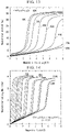
- Fig. 1A is a diagram showing an area in which a magnetization changes with a steep slope with respect to a change in a magnetic field, in a magnetization (M)-magnetic field (H) curve, of a magnetic refrigeration material used in the present invention.
- the magnetization (M)-magnetic field (H) curves at 2 K, 10 K, 20 K, 30 K, 40 K, 50 K, 60 K, 70 K, 80 K, 90 K, and 100 K are shown in order from a curve with a low magnetic field, and the solid lines indicate changes when an external magnetic field is applied, and dotted lines indicate changes when the external magnetic field is reduced.
- the area is divided into five areas: a low-level side gentle slope area; a low-level side connection area; a steep slope area; a high-level side connection area; and a high-level side gentle slope area, in order from a state of low magnetization.
- the low-level side gentle slope area is an area in which the magnetization changes with a gentle slope in response to a change in the magnetic field, and is a spiral magnetic state in which magnetic ion spins of the magnetic refrigeration material are arranged periodically so as to draw a spiral. Focusing on the 40 K graph in Fig. 1A , the low-level side gentle slope area corresponds to an area from the origin O to a boundary point M1.
- the high-level side gentle slope area is an area in which the magnetization changes or saturates with a gentle slope in response to a change in the magnetic field.
- the high-level side gentle slope area corresponds to a magnetic saturation state in which the magnetic ion spins of the magnetic refrigeration material are aligned in a magnetic field direction.
- the high-level side gentle slope area corresponds to an area of the boundary points M4 to M5 in Fig. 1A .
- the steep slope area is an area in which the magnetization changes with a steep slope in response to a change in the magnetic field.
- the steep slope area corresponds to an area from the boundary points M2 to M3 in Fig. 1A .
- the steep slope area has a higher level of magnetization than the low-level side gentle slope area.
- the steep slope area has a lower level of magnetization than the high-level side gentle slope area.
- a steep slope area of magnetization in response to the change in the magnetic field has temperature dependence.
- the steep slope area is, for example, an area in which a rate of change of the magnetization M (T) per unit change of a magnetic field ⁇ 0 H (T) exceeds 1.
- the low-level side connection area is an area in which the low-level side gentle slope area and the steep slope area are connected in the magnetization (M)-magnetic field (H) curve. That is, the low-level side connection area corresponds to an area of the boundary points M1 to M2 in Fig. 1A .
- the high-level side connection area is an area in which the steep slope area and the low-level side gentle slope area are connected in the magnetization (M)-magnetic field (H) curve.
- the high-level side connection area corresponds to an area of the boundary points M3 to M4 in Fig. 1A .
- the five areas of the low-level side gentle slope area, the low-level side connection area, the steep slope area, the high-level side connection area, and the high-level side gentle slope area and boundary points thereof have been described, and the five areas and boundary points exist at any temperature. As the temperature increases, a magnitude of the magnetic field corresponding to the boundary point tends to increase.
- Fig. 1B is a diagram showing a magnetization (M)-magnetic field (H) curve of holmium simple substance.
- the magnetization (M)-magnetic field (H) curves at 2 K, 10 K, 20 K, 30 K, 40 K, 50 K, 60 K, 70 K, 80 K, 90 K, 100 K, and 200 K are shown in order from a curve with a low magnetic field, and the solid lines indicate changes when an external magnetic field is applied, and dotted lines indicate changes when the external magnetic field is reduced.
- the M-H characteristics change depending on the temperature, and rapid magnetization change behavior appears.
- the magnetization increases rapidly over a certain limited magnetic field range. That is, the spin arrangement state changes significantly only in the range.
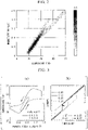
- the amount of change in magnetic entropy (- ⁇ S) when a magnetic field h of 0.1 T is further applied to a magnetic field Ho with a predetermined magnitude is determined from a magnetization-temperature curve using Maxwell relations (see Fig. 2 ).
- the magnitude of ⁇ S is indicated by shading, and it is shown that as the area is darker, the value is larger.
- the maximum value of ⁇ S was 3.0 (Jkg -1 K -1 ).
- the amount of change in magnetic entropy per unit magnetic field ⁇ - ⁇ S/ ⁇ ( ⁇ 0 h) ⁇ was about 6 K.
- the amount of change in magnetic entropy per unit magnetic field ⁇ - ⁇ S/ ⁇ ( ⁇ 0 h) ⁇ in response to varying of the magnetic field is about 5 times the maximum value of the related art at around 30 K. It is considered that this is because the effect of applying a variable magnetic field to a base magnetic field only in a portion where the change in the M-H characteristics is large is obtained.
- FIG. 3(a) shows a correlation diagram between the magnitude of the magnetic field applied to holmium simple substance and the temperature change.
- the correlation diagram shown by the solid line is a correlation diagram of a cycle in which a magnetic field of 1.5 T was applied to no magnetic field and subsequently removed therefrom (hereinafter, referred to as a first cycle; 0 T ⁇ 1.5 T ⁇ 0 T).
- holmium simple substance increased by about 1.6 K from about 27.9 K to 29.5 K when the magnetic field of 1.5 T was applied, and returned to almost an original temperature when returned to a state of no magnetic field.
- the holmium simple substance increased by about 1.5 K from 28.2 K to 29.7 K when the magnetic field h of 0.4 T is further applied to the base magnetic field of 0.5 T, whereas the holmium simple substance decreased and cooled to 28.2 K when demagnetized to 0.5 T. In this manner, it was confirmed that even if the magnetic field variation range was narrowed down to an efficient range using the base magnetic field, the magnetic refrigeration effect was almost the same as when the magnetic field was changed significantly.
- Fig. 3(b) is an explanatory diagram of a thermal cycle showing a relationship between a temperature and magnetic entropy, obtained from Fig. 3(a) .
- the dotted arrow in Fig. 3(b) indicates a change when the magnetic field applied to the holmium simple substance was lowered to 0 T from 1.5 T and adiabatic demagnetization was performed, and a change when the magnetic field applied to the holmium simple substance was lowered to 0.5 T from 0.9 T and the adiabatic demagnetization was performed.
- Fig. 4 is an explanatory diagram showing a thermal cycle of a magnetic refrigeration system showing an example of the present invention, and shows a thermal cycle using a variable magnetic field ⁇ H from a base magnetic field H 0 .
- Fig. 4 shows a comparison between a magnetic refrigeration cycle in a case of using a magnetic field of high magnetic field H1 from a zero magnetic field (isothermal excitation step (A ⁇ B) and adiabatic demagnetization (B ⁇ C)) and a magnetic refrigeration cycle using a variable magnetic field ⁇ H from the base magnetic field Ho (isothermal excitation step (A' ⁇ B') and adiabatic demagnetization step (B' ⁇ C')).
- a change in entropy ⁇ S' and a temperature change ⁇ T' in a thermal cycle of the magnetic refrigeration using the variable magnetic field ⁇ H from the base magnetic field Ho have almost the same effect of the change in entropy ⁇ S and the temperature change ⁇ T in a case of using the magnetic field to a high magnetic field H1 from the zero magnetic field as the magnetic refrigeration thermal cycle (A ⁇ B and B ⁇ C).
- Fig. 5 shows Example 2 of the present invention, and is a diagram showing a temperature change when the magnetic field h of 0.4 T is further applied to a holmium simple substance with the base magnetic field Ho at various temperatures T about from 20 K to 50 K and the h is removed therefrom.
- a magnet that generates a base magnetic field at intervals of 0.033 T from 0.0 T to 1.5 T as a base magnetic field and at the same time generates a variable magnetic field of 0.4 T is set on an outer periphery portion of a simple substance holmium, and a magnetic field to be applied at each base magnetic field was changed.
- Fig. 6 is a diagram showing a temperature change width when a magnetic field h of 0.4 T is further applied to a holmium simple substance with a base magnetic field Ho at various temperatures T about from 10 K to 50 K and the h is removed therefrom.
- the magnitude of the temperature change ⁇ T (K) is indicated by shading, and it is shown that as the area is darker, the value is larger.
- the maximum value of ⁇ T was 1,6 (K).
- holmium which also serves as a heat storage body, could be cooled by 1.2 to 1.5K from any temperature in the range of 20 to 40K.
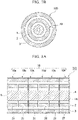
- Fig. 7A is schematic view showing a section of a magnetic refrigeration system 100 according to the present embodiment.
- Fig. 7B shows a cross-sectional view taken along the line VIIB-VIIB of Fig. 7A (VIIB-VIIB line cross-sectional view).
- the magnetic refrigeration system 100 has at least one magnetic refrigeration module 10.
- the magnetic refrigeration system 100 shown in Fig. 7A is an example of a case in which a plurality of magnetic refrigeration modules 10 are provided, and includes six magnetic refrigeration modules 10a to 10f.
- the magnetic refrigeration module 10 includes a magnetic refrigeration operation unit 1, a fixed magnetic field excitation unit 2 located on the outer peripheral direction of the magnetic refrigeration operation unit 1, and a variable magnetic field excitation unit 3.
- the magnetic refrigeration operation unit 1 has a magnetic refrigeration material.
- the magnetic refrigeration operation unit 1 is, for example, a cylindrical or tubular member.
- a particulate, pellet-like, porous, or dense solid material is used for the magnetic refrigeration operation unit 1. End portions in a longitudinal direction in which the magnetic refrigeration operation unit 1 extends are referred to as a first end 4 and a second end 5.
- the longitudinal direction of the magnetic refrigeration operation unit 1 may be referred to as a first direction.
- one of the first end 4 and the second end 5 acts as a high temperature end and the other acts as a low temperature end.
- a refrigerant flow path 6 is formed inside the magnetic refrigeration operation unit 1.
- a gas to be cooled moves through the refrigerant flow path 6 formed inside the magnetic refrigeration operation unit 1, and the magnetic refrigeration system 100 acts.
- the magnetic refrigeration operation unit 1 is in the form of particles, pellets, or a porous having low fluid resistance, the gas to be cooled also flows inside the magnetic refrigeration operation unit 1.
- each magnetic refrigeration module 10 materials having different composition parts may be appropriately combined and used depending on a desired temperature.
- the fixed magnetic field excitation unit 2 includes a plurality of fixed magnetic field excitation units 2a to 2f. Each of the fixed magnetic field excitation units 2a to 2f is provided in each of the magnetic refrigeration modules 10a to 10f.
- a permanent magnet or a superconducting magnet is used as the fixed magnetic field excitation unit 2. In a case where the magnitude of the fixed magnetic field is 1.5 T or less, it is preferable that a permanent magnet is used as the fixed magnetic field excitation unit 2. In a case where the magnitude of the fixed magnetic field is 1.5 T or more, it is preferable that the superconducting magnet is used as the fixed magnetic field excitation unit 2.
- the fixed magnetic field excitation unit 2 applies a fixed magnetic field to the magnetic refrigeration operation unit 1.
- the fixed magnetic field is a magnetic field having a predetermined magnetic field strength, and the magnetic field strength does not vary with a passage of time. It is preferable that the magnetic field strength of the fixed magnetic field becomes higher stepwise along the first direction. For example, it is preferable that the magnetic field strength of the fixed magnetic field excitation unit 2a is the smallest among the fixed magnetic field excitation units 2a to 2f, and the magnetic field strength of the fixed magnetic field excitation unit 2f is the largest among the fixed magnetic field excitation units 2a to 2f.
- variable magnetic field excitation unit 3 At least one selected from a resistive magnet and a superconducting magnet is used. The operation of the variable magnetic field excitation unit 3 will be described in detail later, but in an excitation step and a heat removal step, a variable magnetic field is applied to the magnetic refrigeration operation unit 1.
- a state in which the variable magnetic field excitation unit 3 applies the variable magnetic field to the magnetic refrigeration operation unit 1 may be referred to as an ON state, and a state of non-application may be referred to as an OFF state.
- the magnetic field strength of the fixed magnetic field and the magnetic field strength of the variable magnetic field are set based on the working temperature of the magnetic refrigeration operation unit 1 and the steep slope area.
- the strength of the fixed magnetic field is lower than the strength of the magnetic field corresponding to the steep slope area of the magnetic refrigeration material.
- the sum of the strengths of the fixed magnetic field and the variable magnetic field is higher than the strength of the magnetic field corresponding to the steep slope area of the magnetic refrigeration material.
- the sum of the magnetic field strengths of the fixed magnetic field and the variable magnetic field is equal to or less than the magnetic field corresponding to the steep slope area when being in the OFF state, and equal to or more than the magnetic field corresponding to the steep slope area when being in the ON state.
- the magnetic field strength of the variable magnetic field in the OFF state may be a value larger than 0.
- the temperatures at both ends are set to a predetermined temperature.
- the temperature of the high temperature end 4 is set to be a first temperature
- the temperature of the low temperature end 5 is set to be a second temperature.
- each of the magnetic field strengths applied to the high temperature end 4 and the low temperature end 5 when being in the ON state is higher than the magnetic field strength corresponding to the steep slope area at the first temperature and the magnetic field strength corresponding to the steep slope area at the second temperature.
- each of the magnetic field strengths applied to the high temperature end 4 and the low temperature end 5 when being in the OFF state is lower than the magnetic field strength corresponding to the steep slope area at the first temperature and the magnetic field strength corresponding to the steep slope area at the second temperature.
- the first temperature is, for example, 150 K
- the second temperature is, for example, 10 K.
- Fig. 8A is a cross-sectional view of a magnetic refrigeration system 101 according to Modification Example 1.
- the magnetic refrigeration system 101 is different from the magnetic refrigeration system 100 shown in Fig. 7A in that a magnetic refrigeration operation unit 1A is provided.
- the magnetic refrigeration operation unit 1A does not have a through hole penetrating in the first direction.
- the magnetic refrigeration operation unit 1A is in the form of particles or pellets. Therefore, it is possible to cool the gas to be cooled by flowing the gas inside the magnetic refrigeration operation unit 1A. In this case, it may be considered that the refrigerant flow path is formed inside the magnetic refrigeration operation unit 1A.
- Other configurations are the same as those of the magnetic refrigeration system 100 shown in Fig. 7A , and the description thereof will not be repeated.
- Fig. 8B is a cross-sectional view of a magnetic refrigeration system 102 according to Modification Example 2.
- the magnetic refrigeration system 102 is different from the magnetic refrigeration system 100 shown in Fig. 7A in that the variable magnetic field excitation unit 3B includes a plurality of independent variable magnetic field excitation units 3B to 3f.
- the variable magnetic field excitation unit 3B is distributed so that the magnetic field strength of the variable magnetic field becomes higher stepwise along the first direction when a magnetic field is applied to the magnetic refrigeration operation unit 1.
- the magnetic field strength of the variable magnetic field in the magnetic refrigeration module 10a is the smallest among the variable magnetic fields in the magnetic refrigeration modules 10a to 10f
- the magnetic field strength of the variable magnetic field in the magnetic refrigeration module 10f is the largest among the magnetic refrigeration modules 10a to 10f.
- Fig. 8C is a cross-sectional view of a magnetic refrigeration system 103 according to Modification Example 3.
- the magnetic refrigeration system 103 is different from the magnetic refrigeration system 100 in that a connection pipe 6' is provided.
- the magnetic refrigeration operation unit 1C and the fixed magnetic field excitation unit 2C of the magnetic refrigeration system 103 are not arranged concentrically.
- the magnetic refrigeration operation units in the adjacent magnetic refrigeration modules are connected by the connection pipe 6'.
- a predetermined shape is selected for the connection pipe 6'.
- FIG 8C shows an example in which central positions of the magnetic refrigeration operation unit 1C and the fixed magnetic field excitation unit 2 in each magnetic refrigeration module 10 shift, but a configuration or the like in which thicknesses of the fixed magnetic field excitation unit 2 and the magnetic refrigeration operation unit 1 are different for each magnetic refrigeration module may be adopted. Further, the thickness or a position of the variable magnetic field excitation unit 3 may be appropriately adjusted according to the configurations of the magnetic refrigeration operation unit 1 and the fixed magnetic field excitation unit 2.
- Fig. 9A is a cross-sectional view of a magnetic refrigeration system 104 according to Modification Example 4.
- the magnetic refrigeration system 104 is different from the magnetic refrigeration system 100 shown in Fig. 7A in that the fixed magnetic field excitation unit 2 is located in the outer peripheral direction of the variable magnetic field excitation unit 3.
- Other configurations are the same as those of the magnetic refrigeration system 100 shown in Fig. 7A , and the description thereof will not be repeated.
- Fig. 9B is a cross-sectional view of the magnetic refrigeration system 104 taken along the line IXB-IXB.
- the magnetic refrigeration system When using the magnetic refrigeration system according to the present embodiment, it is possible to carry out a cooling method including an excitation step, a heat removal step, an adiabatic demagnetization step, and a cooling step.
- the gas to be cooled at the first temperature can be used, and the high temperature end 4 can be set to the first temperature and the low temperature end 5 can be set to the second temperature.
- the operation will be described by showing an example using the magnetic refrigeration system 100 shown in Fig. 7A .
- the magnetic refrigeration system 100 according to the present embodiment is not limited to conditions such as numerical values used in this examples.
- the magnetic refrigeration operation unit 1 has a simple substance holmium as a working substance. Therefore, the simple substance holmium may be formed into particles or pellets, may be porous, or may be a dense solid. If the holmium is in the form of particles or pellets, the gas to be cooled can flow inside the magnetic refrigeration operation unit 1. In the case of the dense form, the gas to be cooled becomes flows through the refrigerant flow path 6. In the case of porous, when the fluid resistance is low, the gas to be cooled can flow inside the magnetic refrigeration operation unit 1, but when the fluid resistance is extremely high, the refrigerant flow path 6 is provided and the gas to be cooled flows therethrough.
- An overall shape of the magnetic refrigeration operation unit 1 is preferably cylindrical, but may be rod-shaped, flat plate-shaped, or tubular.
- a reciprocating magnetic field excitation unit is a reciprocating magnetic field excitation unit that generates an operation magnetic field that operates including a steep slope area in the magnetization (M)-magnetic field (H) curve of the magnetic refrigeration material, and performs reciprocating excitation of the magnetic field to be applied between a low-level side connection area side of the steep slope area in the operation magnetic field or the low-level side magnetic field corresponding to the low-level side connection area and a high-level side connection area side of the steep slope area in the operation magnetic field or the high-level side magnetic field corresponding to the high-level side connection area (see Fig. 1A ).
- the operation magnetic field preferably includes the entire steep slope area, but may include at least a part of the steep slope area.
- the reciprocating magnetic field excitation unit is configured of the fixed magnetic field excitation unit 2 and the variable magnetic field excitation unit 3.
- the fixed magnetic field excitation unit 2 applies a magnetic field corresponding to the low-level side connection area of the steep slope area of the magnetic refrigeration material by a fixed magnetic field (H 0 ; H 0 > 0), and is thus made of, for example, a permanent magnet.
- the magnetic field strength of the fixed magnetic field is set to 0.2 T, 0.4 T, 0.6 T, 0.8 T, 1.0 T, and 1.2 T in the fixed magnetic field excitation units 2a, 2b, 2c, 2d, 2e, and 2f, for example.
- the variable magnetic field excitation unit 3 applies a variable magnetic field corresponding to a variable magnetic field amplitude from the low-level side connection area to the high-level side connection area of the steep slope area of the magnetic refrigeration material by the variable magnetic field (h; h > 0) having a constant width, and is thus made of, for example, a normal conducting or superconducting magnet.
- the magnetic field strength of the variable magnetic field when the variable magnetic field excitation unit 3 acts is set to, for example, 0.4 T.
- variable magnetic field excitation unit 3 is provided in a tubular shape on the outer peripheral side of the magnetic refrigeration operation unit 1, and the fixed magnetic field excitation unit 2 is provided in a tubular shape on the outer peripheral side of the variable magnetic field excitation unit 3.
- the fixed magnetic field excitation unit 2 and the variable magnetic field excitation unit 3 may be disposed concentrically in the order shown in Fig. 7A , and may also be disposed in the reverse order.
- the high temperature end 4 is a high temperature end of the magnetic refrigeration operation unit 1, and is located on the high magnetic field side in a case where the magnetic field generated by the fixed magnetic field excitation unit 2 is provided with a high or low slope.
- the high temperature end 4 may have a structure in which heat is exchanged with the gas to be cooled by the flow of a refrigerant, or the gas to be cooled is used as a refrigerant gas.
- the low temperature end 5 is a high temperature end of the magnetic refrigeration operation unit 1, and is located on the low magnetic field side in a case where the magnetic field generated by the fixed magnetic field excitation unit 2 is provided with a high or low slope.
- the low temperature end 5 may have a structure in which heat is exchanged with the gas to be cooled by the flow of a refrigerant, or the gas to be cooled is used as a refrigerant gas.
- the refrigerant flow path 6 is provided along the longitudinal direction of the magnetic refrigeration operation unit 1, and the refrigerant can move between the high temperature end 4 and the low temperature end 5, and the refrigerant existing in the refrigerant flow path 6 is configured to exchange heat with the magnetic refrigeration material.
- the magnetic refrigeration module forming the magnetic refrigeration system will be described.
- ring-shaped permanent magnets are concentrically arranged outside the simple substance holmium forming the magnetic refrigeration operation unit 1 as the fixed magnetic field excitation unit 2, and a ring-shaped resistive magnets that generate a variable magnetic field of 0.4 T are arranged outside the fixed magnetic field excitation unit 2, as the variable magnetic field excitation unit 3.
- the magnetic refrigeration system shown in Fig. 7A is configured of six magnetic refrigeration modules. Adjacent magnetic refrigeration modules have magnetic field strength of the fixed magnetic field from 0.2 T to 1.2 T at intervals of 0.2 T.
- variable magnetic field excitation unit 3 a resistive magnets that generate a variable magnetic field of 0.4 T are arranged outside the fixed magnetic field excitation unit 2.
- the resistive magnet may be provided independently for each magnetic refrigeration module, or may be provided in common with magnetic refrigeration modules.
- a refrigerant flow path 6 through which hydrogen or helium gas to be cooled can pass and exchange heat is provided.
- the refrigerant flow path 6 may be provided independently for each magnetic refrigeration module, or may be provided in common with magnetic refrigeration modules. In a case where the refrigerant flow path 6 is provided independently for each magnetic refrigeration module, it is necessary to provide a connection pipe for connecting refrigerant flow paths 6 to each other.
- Fig. 10 is an explanatory view showing an example of operation steps of the magnetic refrigeration system, in which (a) shows an excitation step, (b) shows a heat removal step, (c) shows an adiabatic demagnetization step, and (d) shows a cooling step.
- variable magnetic field is increased by 0.4 T (in the ON state) to increase the temperature of the simple substance holmium as a working substance contained in the magnetic refrigeration operation unit 1.
- a gas to be cooled of about 50 K is passed from the low temperature end 5 to the high temperature end 4, and heat removal of the simple substance holmium forming the magnetic refrigeration operation unit 1 is performed.
- variable magnetic field is demagnetized to zero (in the OFF state) and the temperature of the simple substance holmium is lowered.
- the gas to be cooled is passed from the high temperature end 4 to the low temperature end 5 to cool the gas to be cooled.
- a magnetic refrigeration system having a temperature gradient of about 50 K at the high temperature end 4 and about 20 K at the low temperature end 5 (17 K for helium) was realized.
- variable magnetic field excitation unit 3 can also be a superconducting magnet, and the energy efficiency is improved by using an oxide superconducting wire and operating at a liquid nitrogen temperature (77 K).
- a magnetic refrigeration system having a temperature gradient of 30 K, about 50 K at the high temperature end and about 20 K at the low temperature end was realized by using a permanent magnet to generate a fixed magnetic field and using a normal conducting (or superconducting) magnet to generate a variable magnetic field.
- Fig. 11 is a schematic view showing a magnetic refrigeration system 105 according to Modification Example A based on Examples 1 and 2 of the present invention.
- the magnetic refrigeration system 105 is different from the magnetic refrigeration system 100 in that only one fixed magnetic field excitation unit 7 is provided.
- the magnetic field strength of the fixed magnetic field changes continuously or stepwise along the first direction.
- the system is divided into magnetic refrigeration modules 10a to 10f as shown in Fig. 11 . Since the magnetic field strengths at both ends of the fixed magnetic field are different from each other, the entire configuration shown in Fig. 11 is a magnetic refrigeration system.
- the magnetic refrigeration system 105 includes at least one magnetic refrigeration module.
- the magnetic refrigeration system 105 includes at least one magnetic refrigeration module.
- superconducting magnets having a magnetic field with a slope of 0.2 to 2.5 T as the fixed magnetic field excitation unit 7 are arranged outside the simple substance holmium configuring the magnetic refrigeration operation unit 1.
- a superconducting or resistive magnet that generates a variable magnetic field of 0.4 T is arranged outside the fixed magnetic field excitation unit 2.
- a refrigerant flow path 6 through which hydrogen or helium gas to be cooled can exchange heat (directly or indirectly).
- variable magnetic field is increased by 0.4 T to increase the temperature of the simple substance holmium as a working substance contained in the magnetic refrigeration operation unit 1.
- variable magnetic field is demagnetized to zero and the temperature of the simple substance holmium is lowered.
- the gas to be cooled is passed from the high temperature end 4 to the low temperature end 5 to cool the gas to be cooled.
- a magnetic refrigeration system having a temperature gradient of 57 K (100 K) of 77 K (or 120 K) at the high temperature end and 20 K (17 K in the case of helium) at the low temperature end was realized by using a gradient magnetic field superconducting magnet to generate a fixed magnetic field and using a normal conducting (or superconducting) magnet to generate a variable magnetic field.
- Fig. 12 shows the magnetization (M)-magnetic field (H) curve of Gd 5 Ge 4 (from 16 K to 100 K in 3 K increments)
- Fig. 13 shows the magnetization (M)-magnetic field (H) curve of Co(S x Se 1-x ) 2
- Fig. 14 shows a magnetization (M)-magnetic field (H) curve of (Gd 0.5 Sm 0.5 ) 0.55 Sr 0.45 MnO 3 .
- the solid line shows the change when the external magnetic field is applied
- the dotted line shows the change when the external magnetic field is decreased.
- Fig. 13 is a diagram showing the magnetization (M)-magnetic field (H) characteristics of Co(S x Se 1-x ) 2 of Modification Example B.
- M magnetization
- H magnetic field
- Gd 5 Ge 4 , Co (S x Se 1-x ) 2 , and (Gd 0.5 Sm 0.5 ) 0.55 Sr 0.45 MnO 3 also have different M-H characteristics depending on the temperature, and the M-H characteristics change rapidly from a certain magnetic field. Therefore, the same magnetic refrigeration effect as that of the simple substance holmium can be expected.
- the optimum magnetic field for the fixed magnetic field varies depending on each substance.
- the steep slope area is located in the area in which the magnetic field strength is 2 to 7 T, and the width thereof is approximately 1 T or less, although the magnetic field strength varies depending on the temperature. Therefore, a continuous gradient magnetic field superconducting magnet from 2 to 7 T is required as a fixed magnetic field, and a superconducting magnet having a variation width of 1 T is required as a variable magnetic field.
- the total magnetic field change of the fixed magnetic field and the variable magnetic field is 2 T to 8 T.
- Other configurations are the same as those of the magnetic refrigeration system 100.
- Modification Example B for example, a magnetic refrigeration system having a 60 K at the high temperature end and 20 K (10 K for helium) at a low temperature end can be realized.
- Table 2 shows examples of typical magnetic refrigeration materials for low temperatures suitable for hydrogen liquefaction.
- Table 2 shows the change in entropy and the entropy change efficiency when only a predetermined variable magnetic field (magnetic field) is applied to the magnetic refrigeration material in a temperature T M without applying a magnetic field as a fixed magnetic field.
- the numerical values after "@" in the column of Entropy change efficiency indicate the magnetic field strength given as the variable magnetic field. For example, in sample A, it is shown that when a variable magnetic field of 5 T is applied, a change by 14.9 (J ⁇ kg -1 ⁇ K -1 ) occurs.
- the entropy change efficiency is the change in entropy when a variable magnetic field of 1 T is applied.
- the temperature, change in entropy, and entropy change efficiency of Sample A, Sample B, and Sample D are based on Japanese Unexamined Patent Application, First Publication No. 2017-39993 .
- the temperature, the change in entropy, and entropy change efficiency of Sample C, Sample E, Sample F, and Sample G are based on PCT International Publication No. 2018/129476 , J. J. Appl. PhysAppl. Phys. 105, 07A934 (2019 ) and Chinese Patent Application Publication No. 1017012408 .
- the magnetic refrigeration operation unit, the fixed magnetic field excitation unit, and the variable magnetic field excitation unit are not provided with a mechanism for changing the mutual positional relationship.
- the magnetic refrigeration module and the magnetic refrigeration system using the same of the present invention may be provided with a substance that causes a magnetic refrigeration material substance to generate heat or absorb heat or a mechanism for reciprocating or rotating a variable magnetic field excitation unit.
- the magnetic refrigeration operation unit may be rod-shaped or flat plate-shaped.
- the fixed magnetic field excitation unit and the variable magnetic field excitation unit may have a sandwich shape in which the magnetic refrigeration operation unit is sandwiched between the upper and lower parts.
- the fixed magnetic field excitation unit includes an upper fixed magnetic field excitation unit and a lower fixed magnetic field excitation unit provided so as to sandwich the magnetic refrigeration operation unit in at least one of the thickness direction and the width direction of the magnetic refrigeration operation unit, and for example, a flat plate-shaped permanent magnet is used.
- the variable magnetic field excitation unit is a flat plate-shaped electromagnet that generates a variable magnetic field in addition to the fixed magnetic field generated by the upper fixed magnetic field excitation unit and the lower fixed magnetic field excitation unit, and may be, for example, a resistive magnet or a superconducting magnet.
- the magnetic refrigeration module of the present invention when changing the magnetic field only in the range where the M-H characteristics change significantly, a highly efficient magnetic refrigeration system can be constructed even when a substance having a single composition is used.
- the magnetic refrigeration system of the present invention when adopting a magnetic field application structure in which a variable magnetic field is superimposed on the base magnetic field, it is possible to apply only the magnetic field range having the largest magnetic refrigeration effect, and the efficiency can be improved.
Landscapes
- Engineering & Computer Science (AREA)
- Mechanical Engineering (AREA)
- Physics & Mathematics (AREA)
- Thermal Sciences (AREA)
- General Engineering & Computer Science (AREA)
- Power Engineering (AREA)
- Chemical & Material Sciences (AREA)
- Materials Engineering (AREA)
- Metallurgy (AREA)
- Organic Chemistry (AREA)
- Hard Magnetic Materials (AREA)
Applications Claiming Priority (2)
| Application Number | Priority Date | Filing Date | Title |
|---|---|---|---|
| JP2019136731 | 2019-07-25 | ||
| PCT/JP2020/027239 WO2021015038A1 (fr) | 2019-07-25 | 2020-07-13 | Module de congélation magnétique, système de congélation magnétique et procédé de refroidissement |
Publications (3)
| Publication Number | Publication Date |
|---|---|
| EP4006189A1 true EP4006189A1 (fr) | 2022-06-01 |
| EP4006189A4 EP4006189A4 (fr) | 2023-08-09 |
| EP4006189B1 EP4006189B1 (fr) | 2025-09-03 |
Family
ID=74193980
Family Applications (1)
| Application Number | Title | Priority Date | Filing Date |
|---|---|---|---|
| EP20844435.6A Active EP4006189B1 (fr) | 2019-07-25 | 2020-07-13 | Module de réfrigération magnétique, système de réfrigération magnétique, et procédé de réfrigération |
Country Status (4)
| Country | Link |
|---|---|
| US (1) | US20220268494A1 (fr) |
| EP (1) | EP4006189B1 (fr) |
| JP (1) | JP7178140B2 (fr) |
| WO (1) | WO2021015038A1 (fr) |
Cited By (3)
| Publication number | Priority date | Publication date | Assignee | Title |
|---|---|---|---|---|
| IT202300008367A1 (it) * | 2023-04-28 | 2024-10-28 | Nuovo Pignone Tecnologie Srl | Impianto di raffreddamento di fluido e relativo modulo refrigerante |
| IT202300008382A1 (it) * | 2023-04-28 | 2024-10-28 | Nuovo Pignone Tecnologie Srl | Modulo refrigerante per un impianto di raffreddamento di fluido e relativo metodo di funzionamento |
| WO2024223085A1 (fr) | 2023-04-28 | 2024-10-31 | Nuovo Pignone Tecnologie - S.R.L. | Installation de refroidissement de fluide et module de fluide frigorigène associé |
Families Citing this family (1)
| Publication number | Priority date | Publication date | Assignee | Title |
|---|---|---|---|---|
| JP7108183B2 (ja) * | 2018-09-27 | 2022-07-28 | ダイキン工業株式会社 | 磁気冷凍システム |
Family Cites Families (18)
| Publication number | Priority date | Publication date | Assignee | Title |
|---|---|---|---|---|
| US5435137A (en) * | 1993-07-08 | 1995-07-25 | Iowa State University Research Foundation, Inc. | Ternary Dy-Er-Al magnetic refrigerants |
| US5887449A (en) * | 1996-07-03 | 1999-03-30 | Iowa State University Research Foundation, Inc. | Dual stage active magnetic regenerator and method |
| US5743095A (en) * | 1996-11-19 | 1998-04-28 | Iowa State University Research Foundation, Inc. | Active magnetic refrigerants based on Gd-Si-Ge material and refrigeration apparatus and process |
| JP3532888B2 (ja) * | 2001-06-26 | 2004-05-31 | 独立行政法人物質・材料研究機構 | 強磁気力場発生装置 |
| JP3759003B2 (ja) * | 2001-07-16 | 2006-03-22 | 独立行政法人科学技術振興機構 | 永久磁石組込型高磁場発生装置 |
| JP2004361061A (ja) * | 2003-06-02 | 2004-12-24 | Shigeru Hiramatsu | 磁気冷凍方法とその磁気冷凍機 |
| JP2005089740A (ja) * | 2003-08-08 | 2005-04-07 | Osaka Industrial Promotion Organization | 磁気冷凍材料および蓄冷材料 |
| JP2009221494A (ja) | 2008-03-13 | 2009-10-01 | Chubu Electric Power Co Inc | 磁気冷凍材料 |
| KR20100099054A (ko) * | 2009-03-02 | 2010-09-10 | 신에쓰 가가꾸 고교 가부시끼가이샤 | 영구 자석식 자계 발생 장치 |
| WO2014013978A1 (fr) * | 2012-07-17 | 2014-01-23 | 日産自動車株式会社 | Dispositif de refroidissement et de chauffage d'air magnétique |
| EP2796811A1 (fr) * | 2013-04-24 | 2014-10-29 | Technical University of Denmark | Dispositif de pompe à chaleur magnétocalorique, système de chauffage ou de refroidissement et ensemble de pompe à chaleur magnétocalorique |
| EP3163223B1 (fr) | 2014-06-26 | 2019-08-07 | National Institute for Materials Science | Dispositif de réfrigération magnétique |
| JP6648884B2 (ja) | 2015-08-21 | 2020-02-14 | 国立研究開発法人物質・材料研究機構 | 磁気冷凍材料 |
| WO2017203922A1 (fr) * | 2016-05-24 | 2017-11-30 | 株式会社デンソー | Dispositif à cycle thermomagnétique |
| WO2018129476A1 (fr) | 2017-01-09 | 2018-07-12 | General Engineering & Research, L.L.C. | Alliages magnétocaloriques utiles pour des applications de réfrigération magnétique |
| JP2018151120A (ja) * | 2017-03-13 | 2018-09-27 | サンデンホールディングス株式会社 | 板状磁気作業体及びこれを使用した磁気ヒートポンプ装置 |
| CN107012408A (zh) | 2017-03-24 | 2017-08-04 | 东南大学 | 一种稀土基高熵块体金属玻璃材料及其制备方法 |
| JP7066265B2 (ja) | 2018-02-09 | 2022-05-13 | 株式会社Fts | フィラーパイプの溶接方法とその装置 |
-
2020
- 2020-07-13 US US17/628,027 patent/US20220268494A1/en active Pending
- 2020-07-13 JP JP2021533954A patent/JP7178140B2/ja active Active
- 2020-07-13 EP EP20844435.6A patent/EP4006189B1/fr active Active
- 2020-07-13 WO PCT/JP2020/027239 patent/WO2021015038A1/fr not_active Ceased
Cited By (3)
| Publication number | Priority date | Publication date | Assignee | Title |
|---|---|---|---|---|
| IT202300008367A1 (it) * | 2023-04-28 | 2024-10-28 | Nuovo Pignone Tecnologie Srl | Impianto di raffreddamento di fluido e relativo modulo refrigerante |
| IT202300008382A1 (it) * | 2023-04-28 | 2024-10-28 | Nuovo Pignone Tecnologie Srl | Modulo refrigerante per un impianto di raffreddamento di fluido e relativo metodo di funzionamento |
| WO2024223085A1 (fr) | 2023-04-28 | 2024-10-31 | Nuovo Pignone Tecnologie - S.R.L. | Installation de refroidissement de fluide et module de fluide frigorigène associé |
Also Published As
| Publication number | Publication date |
|---|---|
| WO2021015038A1 (fr) | 2021-01-28 |
| JP7178140B2 (ja) | 2022-11-25 |
| US20220268494A1 (en) | 2022-08-25 |
| JPWO2021015038A1 (ja) | 2021-12-23 |
| EP4006189A4 (fr) | 2023-08-09 |
| EP4006189B1 (fr) | 2025-09-03 |
Similar Documents
| Publication | Publication Date | Title |
|---|---|---|
| EP4006189B1 (fr) | Module de réfrigération magnétique, système de réfrigération magnétique, et procédé de réfrigération | |
| Balli et al. | Advanced materials for magnetic cooling: Fundamentals and practical aspects | |
| US8099964B2 (en) | Magnetic refrigerating device and magnetic refrigerating method | |
| Pecharsky et al. | Advanced magnetocaloric materials: What does the future hold? | |
| US20080236171A1 (en) | Magnetic refrigerating device and magnetic refrigerating method | |
| US9568223B2 (en) | Magnetocaloric materials for cryogenic liquification | |
| Yu et al. | Review on research of room temperature magnetic refrigeration | |
| US11225703B2 (en) | Magnetocaloric alloys useful for magnetic refrigeration applications | |
| US9784483B2 (en) | Use of rotating magnetic shielding system for a magnetic cooling device | |
| US20080276623A1 (en) | Magnetic refrigerant material | |
| US9970690B2 (en) | Magnetic refrigerator and device including the same | |
| US20100107654A1 (en) | Shimmed active magnetic regenerator for use in thermodynamic devices | |
| Engelbrecht et al. | Recent developments in room temperature active magnetic regenerative refrigeration | |
| Barclay | Active and passive magnetic regenerators in gas/magnetic refrigerators | |
| Gschneidner Jr et al. | Magnetic refrigeration | |
| Orshulevich et al. | Magnetocaloric Effect in Intermetallic Compounds with Rare-Earth and Transition Metals: From Fundamental Aspects to Functional Applications | |
| JP3461114B2 (ja) | 磁気冷却用磁性材料およびそれを用いた磁気冷却装置 | |
| Singal et al. | Magnetic Refrigeration-A Review-A boon for the coming generations | |
| JP2837795B2 (ja) | 極低温蓄冷器 | |
| JP7236505B2 (ja) | 磁気熱量カスケード | |
| Prusty et al. | Giant Magnetocaloric Effect in Cr-and Fe-Substituted Frustrated Magnet Gadolinium Gallium Garnets, Gd3Ga5O12, for Magnetic Cooling at Cryogenic Temperatures | |
| JPH046352A (ja) | 冷凍方法、蓄冷器および液化機 | |
| Mudryk et al. | 5.2 Magnetocaloric materials | |
| Gupta | Magnetic Refrigeration: a Path to Sustainable Hydrogen Liquefaction | |
| Aprea et al. | Magnetocaloric as Solid-State Cooling Technique for Energy Saving |
Legal Events
| Date | Code | Title | Description |
|---|---|---|---|
| STAA | Information on the status of an ep patent application or granted ep patent |
Free format text: STATUS: THE INTERNATIONAL PUBLICATION HAS BEEN MADE |
|
| PUAI | Public reference made under article 153(3) epc to a published international application that has entered the european phase |
Free format text: ORIGINAL CODE: 0009012 |
|
| STAA | Information on the status of an ep patent application or granted ep patent |
Free format text: STATUS: REQUEST FOR EXAMINATION WAS MADE |
|
| 17P | Request for examination filed |
Effective date: 20220120 |
|
| AK | Designated contracting states |
Kind code of ref document: A1 Designated state(s): AL AT BE BG CH CY CZ DE DK EE ES FI FR GB GR HR HU IE IS IT LI LT LU LV MC MK MT NL NO PL PT RO RS SE SI SK SM TR |
|
| DAV | Request for validation of the european patent (deleted) | ||
| DAX | Request for extension of the european patent (deleted) | ||
| A4 | Supplementary search report drawn up and despatched |
Effective date: 20230706 |
|
| RIC1 | Information provided on ipc code assigned before grant |
Ipc: H01F 1/01 20060101ALI20230630BHEP Ipc: F25B 21/00 20060101ALI20230630BHEP Ipc: C22C 28/00 20060101AFI20230630BHEP |
|
| STAA | Information on the status of an ep patent application or granted ep patent |
Free format text: STATUS: EXAMINATION IS IN PROGRESS |
|
| 17Q | First examination report despatched |
Effective date: 20240411 |
|
| GRAP | Despatch of communication of intention to grant a patent |
Free format text: ORIGINAL CODE: EPIDOSNIGR1 |
|
| STAA | Information on the status of an ep patent application or granted ep patent |
Free format text: STATUS: GRANT OF PATENT IS INTENDED |
|
| RIC1 | Information provided on ipc code assigned before grant |
Ipc: F25J 1/02 20060101ALI20250212BHEP Ipc: F25J 1/00 20060101ALI20250212BHEP Ipc: H01F 1/01 20060101ALI20250212BHEP Ipc: F25B 21/00 20060101ALI20250212BHEP Ipc: C22C 28/00 20060101AFI20250212BHEP |
|
| INTG | Intention to grant announced |
Effective date: 20250224 |
|
| GRAS | Grant fee paid |
Free format text: ORIGINAL CODE: EPIDOSNIGR3 |
|
| GRAA | (expected) grant |
Free format text: ORIGINAL CODE: 0009210 |
|
| STAA | Information on the status of an ep patent application or granted ep patent |
Free format text: STATUS: THE PATENT HAS BEEN GRANTED |
|
| AK | Designated contracting states |
Kind code of ref document: B1 Designated state(s): AL AT BE BG CH CY CZ DE DK EE ES FI FR GB GR HR HU IE IS IT LI LT LU LV MC MK MT NL NO PL PT RO RS SE SI SK SM TR |
|
| REG | Reference to a national code |
Ref country code: CH Ref legal event code: EP |
|
| REG | Reference to a national code |
Ref country code: DE Ref legal event code: R096 Ref document number: 602020058198 Country of ref document: DE |
|
| REG | Reference to a national code |
Ref country code: IE Ref legal event code: FG4D |
|
| REG | Reference to a national code |
Ref country code: NL Ref legal event code: MP Effective date: 20250903 |
|
| PG25 | Lapsed in a contracting state [announced via postgrant information from national office to epo] |
Ref country code: NO Free format text: LAPSE BECAUSE OF FAILURE TO SUBMIT A TRANSLATION OF THE DESCRIPTION OR TO PAY THE FEE WITHIN THE PRESCRIBED TIME-LIMIT Effective date: 20251203 |
|
| REG | Reference to a national code |
Ref country code: LT Ref legal event code: MG9D |
|
| PG25 | Lapsed in a contracting state [announced via postgrant information from national office to epo] |
Ref country code: FI Free format text: LAPSE BECAUSE OF FAILURE TO SUBMIT A TRANSLATION OF THE DESCRIPTION OR TO PAY THE FEE WITHIN THE PRESCRIBED TIME-LIMIT Effective date: 20250903 |
|
| PG25 | Lapsed in a contracting state [announced via postgrant information from national office to epo] |
Ref country code: HR Free format text: LAPSE BECAUSE OF FAILURE TO SUBMIT A TRANSLATION OF THE DESCRIPTION OR TO PAY THE FEE WITHIN THE PRESCRIBED TIME-LIMIT Effective date: 20250903 |
|
| PG25 | Lapsed in a contracting state [announced via postgrant information from national office to epo] |
Ref country code: GR Free format text: LAPSE BECAUSE OF FAILURE TO SUBMIT A TRANSLATION OF THE DESCRIPTION OR TO PAY THE FEE WITHIN THE PRESCRIBED TIME-LIMIT Effective date: 20251204 |
|
| PG25 | Lapsed in a contracting state [announced via postgrant information from national office to epo] |
Ref country code: SE Free format text: LAPSE BECAUSE OF FAILURE TO SUBMIT A TRANSLATION OF THE DESCRIPTION OR TO PAY THE FEE WITHIN THE PRESCRIBED TIME-LIMIT Effective date: 20250903 |
|
| PG25 | Lapsed in a contracting state [announced via postgrant information from national office to epo] |
Ref country code: LV Free format text: LAPSE BECAUSE OF FAILURE TO SUBMIT A TRANSLATION OF THE DESCRIPTION OR TO PAY THE FEE WITHIN THE PRESCRIBED TIME-LIMIT Effective date: 20250903 |
|
| PG25 | Lapsed in a contracting state [announced via postgrant information from national office to epo] |
Ref country code: BG Free format text: LAPSE BECAUSE OF FAILURE TO SUBMIT A TRANSLATION OF THE DESCRIPTION OR TO PAY THE FEE WITHIN THE PRESCRIBED TIME-LIMIT Effective date: 20250903 Ref country code: PL Free format text: LAPSE BECAUSE OF FAILURE TO SUBMIT A TRANSLATION OF THE DESCRIPTION OR TO PAY THE FEE WITHIN THE PRESCRIBED TIME-LIMIT Effective date: 20250903 |
|
| PG25 | Lapsed in a contracting state [announced via postgrant information from national office to epo] |
Ref country code: RS Free format text: LAPSE BECAUSE OF FAILURE TO SUBMIT A TRANSLATION OF THE DESCRIPTION OR TO PAY THE FEE WITHIN THE PRESCRIBED TIME-LIMIT Effective date: 20251203 |
|
| PG25 | Lapsed in a contracting state [announced via postgrant information from national office to epo] |
Ref country code: ES Free format text: LAPSE BECAUSE OF FAILURE TO SUBMIT A TRANSLATION OF THE DESCRIPTION OR TO PAY THE FEE WITHIN THE PRESCRIBED TIME-LIMIT Effective date: 20250903 |
|
| REG | Reference to a national code |
Ref country code: AT Ref legal event code: MK05 Ref document number: 1833144 Country of ref document: AT Kind code of ref document: T Effective date: 20250903 |
|
| PG25 | Lapsed in a contracting state [announced via postgrant information from national office to epo] |
Ref country code: NL Free format text: LAPSE BECAUSE OF FAILURE TO SUBMIT A TRANSLATION OF THE DESCRIPTION OR TO PAY THE FEE WITHIN THE PRESCRIBED TIME-LIMIT Effective date: 20250903 |
|
| PG25 | Lapsed in a contracting state [announced via postgrant information from national office to epo] |
Ref country code: SM Free format text: LAPSE BECAUSE OF FAILURE TO SUBMIT A TRANSLATION OF THE DESCRIPTION OR TO PAY THE FEE WITHIN THE PRESCRIBED TIME-LIMIT Effective date: 20250903 |
|
| PG25 | Lapsed in a contracting state [announced via postgrant information from national office to epo] |
Ref country code: AT Free format text: LAPSE BECAUSE OF FAILURE TO SUBMIT A TRANSLATION OF THE DESCRIPTION OR TO PAY THE FEE WITHIN THE PRESCRIBED TIME-LIMIT Effective date: 20250903 |
|
| PG25 | Lapsed in a contracting state [announced via postgrant information from national office to epo] |
Ref country code: IT Free format text: LAPSE BECAUSE OF FAILURE TO SUBMIT A TRANSLATION OF THE DESCRIPTION OR TO PAY THE FEE WITHIN THE PRESCRIBED TIME-LIMIT Effective date: 20250903 |
|
| PG25 | Lapsed in a contracting state [announced via postgrant information from national office to epo] |
Ref country code: IS Free format text: LAPSE BECAUSE OF FAILURE TO SUBMIT A TRANSLATION OF THE DESCRIPTION OR TO PAY THE FEE WITHIN THE PRESCRIBED TIME-LIMIT Effective date: 20260103 |
|
| PG25 | Lapsed in a contracting state [announced via postgrant information from national office to epo] |
Ref country code: PT Free format text: LAPSE BECAUSE OF FAILURE TO SUBMIT A TRANSLATION OF THE DESCRIPTION OR TO PAY THE FEE WITHIN THE PRESCRIBED TIME-LIMIT Effective date: 20260105 Ref country code: CZ Free format text: LAPSE BECAUSE OF FAILURE TO SUBMIT A TRANSLATION OF THE DESCRIPTION OR TO PAY THE FEE WITHIN THE PRESCRIBED TIME-LIMIT Effective date: 20250903 |
|
| PG25 | Lapsed in a contracting state [announced via postgrant information from national office to epo] |
Ref country code: EE Free format text: LAPSE BECAUSE OF FAILURE TO SUBMIT A TRANSLATION OF THE DESCRIPTION OR TO PAY THE FEE WITHIN THE PRESCRIBED TIME-LIMIT Effective date: 20250903 Ref country code: SK Free format text: LAPSE BECAUSE OF FAILURE TO SUBMIT A TRANSLATION OF THE DESCRIPTION OR TO PAY THE FEE WITHIN THE PRESCRIBED TIME-LIMIT Effective date: 20250903 |