EP4006209A1 - Wasserstoffreinigungssystem - Google Patents
Wasserstoffreinigungssystem Download PDFInfo
- Publication number
- EP4006209A1 EP4006209A1 EP20842673.4A EP20842673A EP4006209A1 EP 4006209 A1 EP4006209 A1 EP 4006209A1 EP 20842673 A EP20842673 A EP 20842673A EP 4006209 A1 EP4006209 A1 EP 4006209A1
- Authority
- EP
- European Patent Office
- Prior art keywords
- anode
- hydrogen
- cathode
- gas
- electrolyte membrane
- Prior art date
- Legal status (The legal status is an assumption and is not a legal conclusion. Google has not performed a legal analysis and makes no representation as to the accuracy of the status listed.)
- Pending
Links
Images

Classifications
-
- C—CHEMISTRY; METALLURGY
- C01—INORGANIC CHEMISTRY
- C01B—NON-METALLIC ELEMENTS; COMPOUNDS THEREOF; METALLOIDS OR COMPOUNDS THEREOF NOT COVERED BY SUBCLASS C01C
- C01B3/00—Hydrogen; Gaseous mixtures containing hydrogen; Separation of hydrogen from mixtures containing it; Purification of hydrogen; Reversible storage of hydrogen
- C01B3/02—Production of hydrogen; Production of gaseous mixtures containing hydrogen
- C01B3/32—Production of hydrogen; Production of gaseous mixtures containing hydrogen by reaction of gaseous or liquid organic compounds with gasifying agents, e.g. water, carbon dioxide or air
- C01B3/34—Production of hydrogen; Production of gaseous mixtures containing hydrogen by reaction of gaseous or liquid organic compounds with gasifying agents, e.g. water, carbon dioxide or air by reaction of hydrocarbons with gasifying agents
- C01B3/38—Production of hydrogen; Production of gaseous mixtures containing hydrogen by reaction of gaseous or liquid organic compounds with gasifying agents, e.g. water, carbon dioxide or air by reaction of hydrocarbons with gasifying agents using catalysts
- C01B3/384—Production of hydrogen; Production of gaseous mixtures containing hydrogen by reaction of gaseous or liquid organic compounds with gasifying agents, e.g. water, carbon dioxide or air by reaction of hydrocarbons with gasifying agents using catalysts with external heating of the catalyst
-
- B—PERFORMING OPERATIONS; TRANSPORTING
- B01—PHYSICAL OR CHEMICAL PROCESSES OR APPARATUS IN GENERAL
- B01D—SEPARATION
- B01D53/00—Separation of gases or vapours; Recovering vapours of volatile solvents from gases; Chemical or biological purification of waste gases, e.g. engine exhaust gases, smoke, fumes, flue gases, aerosols
- B01D53/32—Separation of gases or vapours; Recovering vapours of volatile solvents from gases; Chemical or biological purification of waste gases, e.g. engine exhaust gases, smoke, fumes, flue gases, aerosols by electrical effects other than those provided for in group B01D61/00
- B01D53/326—Separation of gases or vapours; Recovering vapours of volatile solvents from gases; Chemical or biological purification of waste gases, e.g. engine exhaust gases, smoke, fumes, flue gases, aerosols by electrical effects other than those provided for in group B01D61/00 in electrochemical cells
-
- C—CHEMISTRY; METALLURGY
- C01—INORGANIC CHEMISTRY
- C01B—NON-METALLIC ELEMENTS; COMPOUNDS THEREOF; METALLOIDS OR COMPOUNDS THEREOF NOT COVERED BY SUBCLASS C01C
- C01B3/00—Hydrogen; Gaseous mixtures containing hydrogen; Separation of hydrogen from mixtures containing it; Purification of hydrogen; Reversible storage of hydrogen
- C01B3/50—Separation of hydrogen or hydrogen-containing gases from gaseous mixtures, e.g. purification
-
- C—CHEMISTRY; METALLURGY
- C25—ELECTROLYTIC OR ELECTROPHORETIC PROCESSES; APPARATUS THEREFOR
- C25B—ELECTROLYTIC OR ELECTROPHORETIC PROCESSES FOR THE PRODUCTION OF COMPOUNDS OR NON-METALS; APPARATUS THEREFOR
- C25B1/00—Electrolytic production of inorganic compounds or non-metals
- C25B1/01—Products
- C25B1/02—Hydrogen or oxygen
-
- C—CHEMISTRY; METALLURGY
- C25—ELECTROLYTIC OR ELECTROPHORETIC PROCESSES; APPARATUS THEREFOR
- C25B—ELECTROLYTIC OR ELECTROPHORETIC PROCESSES FOR THE PRODUCTION OF COMPOUNDS OR NON-METALS; APPARATUS THEREFOR
- C25B9/00—Cells or assemblies of cells; Constructional parts of cells; Assemblies of constructional parts, e.g. electrode-diaphragm assemblies; Process-related cell features
- C25B9/17—Cells comprising dimensionally-stable non-movable electrodes; Assemblies of constructional parts thereof
- C25B9/19—Cells comprising dimensionally-stable non-movable electrodes; Assemblies of constructional parts thereof with diaphragms
- C25B9/23—Cells comprising dimensionally-stable non-movable electrodes; Assemblies of constructional parts thereof with diaphragms comprising ion-exchange membranes in or on which electrode material is embedded
-
- C—CHEMISTRY; METALLURGY
- C25—ELECTROLYTIC OR ELECTROPHORETIC PROCESSES; APPARATUS THEREFOR
- C25B—ELECTROLYTIC OR ELECTROPHORETIC PROCESSES FOR THE PRODUCTION OF COMPOUNDS OR NON-METALS; APPARATUS THEREFOR
- C25B9/00—Cells or assemblies of cells; Constructional parts of cells; Assemblies of constructional parts, e.g. electrode-diaphragm assemblies; Process-related cell features
- C25B9/70—Assemblies comprising two or more cells
-
- H—ELECTRICITY
- H01—ELECTRIC ELEMENTS
- H01M—PROCESSES OR MEANS, e.g. BATTERIES, FOR THE DIRECT CONVERSION OF CHEMICAL ENERGY INTO ELECTRICAL ENERGY
- H01M8/00—Fuel cells; Manufacture thereof
- H01M8/06—Combination of fuel cells with means for production of reactants or for treatment of residues
- H01M8/0662—Treatment of gaseous reactants or gaseous residues, e.g. cleaning
- H01M8/0681—Reactant purification by the use of electrochemical cells
-
- B—PERFORMING OPERATIONS; TRANSPORTING
- B01—PHYSICAL OR CHEMICAL PROCESSES OR APPARATUS IN GENERAL
- B01D—SEPARATION
- B01D2256/00—Main component in the product gas stream after treatment
- B01D2256/16—Hydrogen
-
- B—PERFORMING OPERATIONS; TRANSPORTING
- B01—PHYSICAL OR CHEMICAL PROCESSES OR APPARATUS IN GENERAL
- B01D—SEPARATION
- B01D2257/00—Components to be removed
- B01D2257/80—Water
-
- H—ELECTRICITY
- H01—ELECTRIC ELEMENTS
- H01M—PROCESSES OR MEANS, e.g. BATTERIES, FOR THE DIRECT CONVERSION OF CHEMICAL ENERGY INTO ELECTRICAL ENERGY
- H01M8/00—Fuel cells; Manufacture thereof
- H01M8/10—Fuel cells with solid electrolytes
- H01M2008/1095—Fuel cells with polymeric electrolytes
-
- Y—GENERAL TAGGING OF NEW TECHNOLOGICAL DEVELOPMENTS; GENERAL TAGGING OF CROSS-SECTIONAL TECHNOLOGIES SPANNING OVER SEVERAL SECTIONS OF THE IPC; TECHNICAL SUBJECTS COVERED BY FORMER USPC CROSS-REFERENCE ART COLLECTIONS [XRACs] AND DIGESTS
- Y02—TECHNOLOGIES OR APPLICATIONS FOR MITIGATION OR ADAPTATION AGAINST CLIMATE CHANGE
- Y02E—REDUCTION OF GREENHOUSE GAS [GHG] EMISSIONS, RELATED TO ENERGY GENERATION, TRANSMISSION OR DISTRIBUTION
- Y02E60/00—Enabling technologies; Technologies with a potential or indirect contribution to GHG emissions mitigation
- Y02E60/30—Hydrogen technology
- Y02E60/36—Hydrogen production from non-carbon containing sources, e.g. by water electrolysis
-
- Y—GENERAL TAGGING OF NEW TECHNOLOGICAL DEVELOPMENTS; GENERAL TAGGING OF CROSS-SECTIONAL TECHNOLOGIES SPANNING OVER SEVERAL SECTIONS OF THE IPC; TECHNICAL SUBJECTS COVERED BY FORMER USPC CROSS-REFERENCE ART COLLECTIONS [XRACs] AND DIGESTS
- Y02—TECHNOLOGIES OR APPLICATIONS FOR MITIGATION OR ADAPTATION AGAINST CLIMATE CHANGE
- Y02E—REDUCTION OF GREENHOUSE GAS [GHG] EMISSIONS, RELATED TO ENERGY GENERATION, TRANSMISSION OR DISTRIBUTION
- Y02E60/00—Enabling technologies; Technologies with a potential or indirect contribution to GHG emissions mitigation
- Y02E60/30—Hydrogen technology
- Y02E60/50—Fuel cells
Definitions
- the present disclosure relates to a hydrogen purification system which includes a hydrogen production device that produces hydrogen-containing gas from raw material gas and a plurality of electrochemical devices that purify the hydrogen-containing gas to produce purified hydrogen gas with high purity.
- the hydrogen purification system produces highly purified hydrogen gas that is high purity hydrogen by causing the electrochemical devices to produce purified hydrogen gas.
- a conventional hydrogen purification system produces highly purified hydrogen gas with high hydrogen purity by using two electrochemical devices each of which includes an electrolyte membrane sandwiched between an anode and a cathode and connecting the cathode of the upstream electrochemical device and the anode of the downstream electrochemical device.
- the electrochemical devices electrochemically separate hydrogen from the hydrogen-containing gas containing impurities for purification (see, for example, Non-Patent Literature (NPTL) 1).
- hydrogen-containing gas is supplied, to the anode of an electrochemical device, from a hydrogen production device which reforms raw material gas to produce hydrogen-containing gas.
- the anode off-gas discharged from the anode is supplied to a combustor that controls the temperature of the reforming reaction in the hydrogen production device, and the anode off-gas is used for the combustion of the reforming reaction (see, for example, Patent Literature (PTL) 1).
- PTL Patent Literature
- a conventional hydrogen purification system generally uses a plurality of electrochemical devices to produce highly purified hydrogen gas with high purity, and supplies the anode off-gas of each electrochemical device to a combustor.
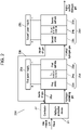
- FIG. 2 is a block diagram illustrating a configuration of a conventional hydrogen purification system.
- conventional hydrogen purification system 200 includes hydrogen production device 21, first electrochemical device 25a, second electrochemical device 25b, first power supply 26a, second power supply 26b, combustor 27, first circulation path 28a, and second circulation path 28b.
- First electrochemical device 25a includes first anode 22a, first cathode 23a, and first electrolyte membrane 24a.
- Second electrochemical device 25b includes second anode 22b, second cathode 23b, and second electrolyte membrane 24b.
- the hydrogen-containing gas produced by hydrogen production device 21 is supplied to first anode 22a.
- the purified hydrogen gas discharged from first cathode 23a is supplied to second anode 22b.
- First power supply 26a applies current between first anode 22a and first cathode 23a.
- Second power supply 26b applies current between second anode 22b and second cathode 23b.
- Combustor 27 combusts the anode off-gas to heat hydrogen production device 21.
- First circulation path 28a supplies, to combustor 27, the anode off-gas discharged from first anode 22a.
- Second circulation path 28b supplies, to combustor 27, the anode off-gas discharged from second anode 22b.
- first electrochemical device 25a for example, an electrolyte membrane-electrode assembly (MEA), in which first electrolyte membrane 24a that selectively transports protons is sandwiched between first anode 22a and first cathode 23a, is sandwiched between a pair of separators.
- MEA electrolyte membrane-electrode assembly
- second electrochemical device 25b for example, an electrolyte MEA, in which second electrolyte membrane 24b that selectively transports protons is sandwiched between second anode 22b and second cathode 23b, is sandwiched between a pair of separators.
- the purified hydrogen gas discharged from first cathode 23a is supplied to second anode 22b, and current is applied between second anode 22b and second cathode 23b. This causes an oxidation reaction of (Chem. 1) in second anode 22b, and causes a reduction reaction of (Chem. 2) in second cathode 23b.
- the hydrogen-containing gas contained in the hydrogen-containing gas supplied to first anode 22a and discharged from first anode 22a without permeating first electrolyte membrane 24a from first anode 22a to first cathode 23a is defined as anode off-gas.
- the anode off-gas is supplied to combustor 27 via first circulation path 28a and is combusted by combustor 27, so that hydrogen production device 21 is heated.
- the hydrogen-containing gas contained in the purified hydrogen gas supplied to second anode 22b and discharged from second anode 22b without permeating second electrolyte membrane 24b from second anode 22b to second cathode 23b is supplied to combustor 27 via second circulation path 28b, and is combusted by combustor 27, so that hydrogen production device 21 is heated.
- the proportion of the flow rate of the purified hydrogen gas discharged from first cathode 23a in the flow rate of the hydrogen-containing gas supplied to first anode 22a, and the proportion of the flow rate of the purified hydrogen gas discharged from second cathode 23a in the flow rate of the purified hydrogen gas supplied to second anode 22b are defined as a hydrogen utilization rate.
- First electrochemical device 25a and second electrochemical device 25b operate at a predetermined hydrogen utilization rate. When the hydrogen utilization rate of the electrochemical devices is 100%, the anode off-gas supplied to combustor 27 is 0. In such a case, excessive temperature rise of hydrogen production device 21 does not occur, but the deterioration of the electrochemical devices is accelerated. Accordingly, the hydrogen utilization rate of the electrochemical devices is generally set to a value that is less than 100%.
- NPTL 1 H. K. Lee, H. Y. Choi, K. H. Choi, J. H. Park, T. H. Lee, Journal of Power Sources 132 (2004) 92-98 .
- the anode off-gas of all electrochemical devices is supplied to the combustor. Accordingly, when the hydrogen utilization rate of the electrochemical devices is kept at a predetermined value, the amount of anode off-gas supplied to the combustor increases as the number of electrochemical devices connected in series increases. Hence, there is a problem in that the hydrogen production device deteriorates due to excessive temperature rise, and a problem in that the efficiency is reduced by combustion of the anode off-gas having a relatively high hydrogen purity of the non-most upstream electrochemical device.
- An object of the present disclosure is to provide a hydrogen purification system in which the amount of anode off-gas supplied to the combustor does not increase even when the number of electrochemical devices connected in series increases.
- the anode off-gas of the most upstream electrochemical device of the plurality of electrochemical devices connected in series is supplied to the combustor which heats the hydrogen production device.
- the anode off-gas of the non-most upstream electrochemical device is mixed with the gas to be supplied to the anode of the non-most upstream electrochemical device or the anode of the electrochemical device upstream of the non-most upstream electrochemical device.
- the amount of anode off-gas supplied to the combustor does not increase.
- the hydrogen purification system according to the present disclosure is capable of preventing the amount of anode off-gas supplied to the combustor from increasing even when the number of electrochemical devices connected in series increases and the hydrogen utilization rate of the electrochemical devices is kept at a predetermined value.
- a hydrogen purification system includes: a plurality of electrochemical devices each of which includes an electrolyte membrane-electrode assembly (MEA) including an electrolyte membrane, an anode disposed on a first surface of the electrolyte membrane, and a cathode disposed on a second surface of the electrolyte membrane, the cathode discharging purified hydrogen gas upon a supply of hydrogen-containing gas to the anode and an application of current between the anode and the cathode in a predetermined direction, the purified hydrogen gas having a hydrogen purity higher than a hydrogen purity of the hydrogen-containing gas supplied to the anode; a hydrogen production device which supplies the hydrogen-containing gas produced from raw material gas; a power supply which applies the current between the anode and the cathode of each of the plurality of electrochemical devices; and a combustor which heats the hydrogen production device.
- MEA electrolyte membrane-electrode assembly
- the plurality of electrochemical devices are connected in series such that the hydrogen production device supplies the hydrogen-containing gas to the anode of a most upstream electrochemical device of the plurality of electrochemical devices, purified hydrogen gas discharged from the cathode of the most upstream electrochemical device is supplied to the anode of one of the plurality of electrochemical devices that is adjacent to the most upstream electrochemical device, and among adjacent ones of the plurality of electrochemical devices, purified hydrogen gas discharged from the cathode of an upstream electrochemical device is supplied to the anode of a downstream electrochemical device.
- the combustor combusts hydrogen-containing gas contained in the hydrogen-containing gas supplied to the anode of the most upstream electrochemical device and discharged from the anode of the most upstream electrochemical device without permeating the electrolyte membrane from the anode to the cathode of the most upstream electrochemical device.
- the purified hydrogen gas contained in the purified hydrogen gas supplied to the anode of a non-most upstream electrochemical device and discharged from the anode of the non-most upstream electrochemical device without permeating the electrolyte membrane from the anode to the cathode of the non-most upstream electrochemical device is mixed with the gas to be supplied to the anode of the non-most upstream electrochemical device.
- a hydrogen purification system includes: a first electrochemical device which includes a first electrolyte membrane-electrode assembly (MEA) including a first electrolyte membrane, a first anode disposed on a first surface of the first electrolyte membrane, and a first cathode disposed on a second surface of the first electrolyte membrane, the first cathode discharging purified hydrogen gas upon a supply of hydrogen-containing gas to the first anode and an application of current between the first anode and the first cathode in a predetermined direction, the purified hydrogen gas having a hydrogen purity higher than the hydrogen-containing gas; a second electrochemical device which is connected in series with the first electrochemical device and includes a second MEA including a second electrolyte membrane, a second anode disposed on a first surface of the second electrolyte membrane, and a second cathode disposed on a second surface of the second electrolyte membrane, the second cathode discharging highly
- FIG. 1 is a block diagram illustrating a configuration of a hydrogen purification system according to a first embodiment of the present disclosure.
- hydrogen purification system 100 includes hydrogen production device 1, first electrochemical device 5a, second electrochemical device 5b, first power supply 6a, second power supply 6b, combustor 7 which combusts anode off-gas to heat hydrogen production device 1, first circulation path 8a, second circulation path 8b, and pump 9.
- Hydrogen production device 1 uses raw material gas and water to produce hydrogen-containing gas by reforming reaction.
- Hydrogen production device 1 includes a reforming catalyst (not illustrated) and combustor 7. Water is heated inside hydrogen production device 1 and becomes steam, which reacts with the raw material gas in the reforming catalyst to produce hydrogen-containing gas.
- As the raw material gas city gas is used which contains methane as a main component.
- First electrochemical device 5a includes an electrolyte membrane-electrode assembly (MEA) sandwiched between a pair of separators.
- the MEA includes first anode 2a, first cathode 3a, and first electrolyte membrane 4a which is sandwiched between first anode 2a and first cathode 3a.
- the hydrogen-containing gas produced by hydrogen production device 1 is supplied to first anode 2a of first electrochemical device 5a.
- hydrogen in the hydrogen-containing gas supplied to first anode 2a is selectively and electrically transported to first cathode 3a through first electrolyte membrane 4a.
- purified hydrogen gas having a higher hydrogen purity than the hydrogen-containing gas supplied to first anode 2a is discharged from first cathode 3a.
- Second electrochemical device 5b includes an electrolyte MEA sandwiched between a pair of separators.
- the MEA includes second anode 2b, second cathode 3b, and second electrolyte membrane 4b which is sandwiched between second anode 2b and second cathode 3b.
- the purified hydrogen gas discharged from first cathode 3a of first electrochemical device 5a is supplied to second anode 2b.
- hydrogen in the hydrogen-containing gas supplied to second anode 2b is selectively and electrically transported to second cathode 3b through second electrolyte membrane 4b.
- highly purified hydrogen gas having a higher hydrogen purity than the purified hydrogen gas supplied to second anode 2b is discharged from second cathode 3b.
- First power supply 6a is a direct current (DC) power supply which includes a positive terminal electrically connected to first anode 2a and a negative terminal electrically connected to first cathode 3a.
- First power supply 6a applies current in the direction from first anode 2a to first cathode 3a of first electrochemical device 5a through first electrolyte membrane 4a.
- Second power supply 6b is a DC power supply which includes a positive terminal electrically connected to second anode 2b and a negative terminal electrically connected to second cathode 3b. Second power supply 6b applies current in the direction from second anode 2b to second cathode 3b of second electrochemical device 5b through second electrolyte membrane 4b.
- First circulation path 8a is a path for supplying, to combustor 7, anode off-gas, that is, the hydrogen-containing gas contained in the hydrogen-containing gas supplied from hydrogen production device 1 to first anode 2a and discharged from first anode 2a without permeating first electrolyte membrane 4a from first anode 2a to first cathode 3a.
- Second circulation path 8b is a path for mixing, with the purified hydrogen gas to be supplied from first cathode 3a to second anode 2b, the purified hydrogen gas contained in the purified hydrogen gas supplied from first cathode 3a to second anode 2b and discharged from second anode 2b without permeating second electrolyte membrane 4b from second anode 2b to second cathode 3b.
- Pump 9 is provided in second circulation path 8b. Pump 9 mixes, with the purified hydrogen gas to be supplied from first cathode 3a to second anode 2b, the purified hydrogen gas contained in the purified hydrogen gas supplied to second anode 2b and discharged from second anode 2b without permeating second electrolyte membrane 4b from second anode 2b to second cathode 3b.
- Hydrogen production device 1 is connected to first anode 2a of first electrochemical device 5a such that the hydrogen-containing gas produced by hydrogen production device 1 is supplied to first anode 2a of first electrochemical device 5a.
- Second electrochemical device 5b is connected to first cathode 3a of first electrochemical device 5a such that the purified hydrogen gas discharged from first cathode 3a is supplied to second anode 2b.
- the flow rate of highly purified hydrogen gas produced by hydrogen purification system 100 is 10 L/min.
- the value of current flowing through first power supply 6a is set to 9.5 A.
- Purified hydrogen gas is discharged from first cathode 3a at a flow rate of 10 L/min.
- the value of current flowing through second power supply 6b is set to 9.5 A.
- Highly purified hydrogen gas is discharged from second cathode 3b at a flow rate of 10 L/min.
- the hydrogen utilization rate of first electrochemical device 5a and second electrochemical device 5b is set to 83.3 %.
- the hydrogen-containing gas is supplied to combustor 7 at a flow rate of 2 L/min.
- hydrogen production device 1 produces hydrogen-containing gas such that the flow rate of the hydrogen-containing gas to be supplied to first anode 2a is 12 L/min.
- purified hydrogen gas is discharged from first cathode 3a at a flow rate of 10 L/min.
- the hydrogen-containing gas, contained in the hydrogen-containing gas supplied to first anode 2a and discharged from first anode 2a without permeating first electrolyte membrane 4a from first anode 2a to first cathode 3a is supplied to combustor 7 via first circulation path 8a at a flow rate of 2 L/min.
- connection destination of first circulation path 8a and the connection destination of second circulation path 8b are different from each other.
- the hydrogen-containing gas discharged from first anode 2a is supplied to combustor 7, but the purified hydrogen gas discharged from second anode 2b is not supplied to combustor 7.
- hydrogen purification system 100 includes first electrochemical device 5a and second electrochemical device 5b which are connected in series such that the purified hydrogen gas discharged from first cathode 3a is supplied to second anode 2b, hydrogen production device 1, first power supply 6a, second power supply 6b, combustor 7, second recirculation path 8b, and pump 9.
- Hydrogen production device 1 supplies hydrogen-containing gas produced from the raw material gas to first anode 2a.
- First power supply 6a applies current in the direction from first anode 2a to first cathode 3a through first electrolyte membrane 4a.
- Second power supply 6b applies current in the direction from second anode 2b to second cathode 3b of second electrochemical device 5b through second electrolyte membrane 4b.
- Combustor 7 is connected to first anode 2a via first circulation path 8a, and combusts the hydrogen-containing gas discharged from first anode 2a to heat hydrogen production device 1.
- Second circulation path 8b mixes the purified hydrogen gas discharged from second anode 2b with the purified hydrogen gas to be supplied from first cathode 3a to second anode 2b.
- Pump 9 is provided in second circulation path 8b to mix the purified hydrogen gas discharged from second anode 2b with the purified hydrogen gas to be supplied from first cathode 3a to second anode 2b.
- the hydrogen utilization rate of first electrochemical device 5a and second electrochemical device 5b is set to 83.3%.
- the hydrogen-containing gas supplied to combustor 7 includes only the hydrogen-containing gas supplied from first anode 2a via first circulation path 8a, that is, the hydrogen-containing gas from one electrochemical device, and the purified hydrogen gas discharged from second anode 2b is supplied to second anode 2b. Accordingly, the anode off-gas of second electrochemical device 5b can be effectively used, leading to an efficient hydrogen purification system.
- hydrogen purification system 100 even when hydrogen is purified with an increased number of electrochemical devices connected in series downstream of second electrochemical device 5b and with the hydrogen utilization rate of the electrochemical devices set to a predetermined value, the flow rate of the hydrogen-containing gas supplied to combustor 7 does not increase. Accordingly, it is possible to achieve hydrogen purification system 100 in which excessive temperature rise of hydrogen production device 1 does not occur and deterioration is reduced.
- the example has been described in which the anode off-gas of second electrochemical device 5b is mixed with the purified hydrogen gas to be supplied to second anode 2b.
- the present disclosure is not limited to such an example.
- the anode off-gas of second electrochemical device 5b may be mixed with the hydrogen-containing gas to be supplied to first anode 2a. In such a case, the amount of anode off-gas supplied to combustor 7 does not increase.
- a circulation path may be provided for mixing the anode off-gas of the third electrochemical device with at least one of the purified hydrogen gas to be supplied to second anode 2b and the gas to be supplied to the third anode (not illustrated).
- the amount of anode off-gas supplied to the combustor does not increase even when the number of electrochemical devices connected in series increases and the hydrogen utilization rate of the electrochemical devices is kept at a predetermined value. Accordingly, the hydrogen purification system can be used in an application where a plurality of electrochemical devices connected in series are used to produce highly purified hydrogen gas having high hydrogen purity from the hydrogen-containing gas produced by the hydrogen production device.
Landscapes
- Chemical & Material Sciences (AREA)
- Chemical Kinetics & Catalysis (AREA)
- Engineering & Computer Science (AREA)
- Organic Chemistry (AREA)
- Electrochemistry (AREA)
- Materials Engineering (AREA)
- Metallurgy (AREA)
- Inorganic Chemistry (AREA)
- Combustion & Propulsion (AREA)
- General Chemical & Material Sciences (AREA)
- Oil, Petroleum & Natural Gas (AREA)
- Analytical Chemistry (AREA)
- Health & Medical Sciences (AREA)
- General Health & Medical Sciences (AREA)
- Life Sciences & Earth Sciences (AREA)
- Manufacturing & Machinery (AREA)
- Sustainable Development (AREA)
- Sustainable Energy (AREA)
- Hydrogen, Water And Hydrids (AREA)
- Electrolytic Production Of Non-Metals, Compounds, Apparatuses Therefor (AREA)
- Separation Using Semi-Permeable Membranes (AREA)
Applications Claiming Priority (2)
| Application Number | Priority Date | Filing Date | Title |
|---|---|---|---|
| JP2019136932 | 2019-07-25 | ||
| PCT/JP2020/026633 WO2021014969A1 (ja) | 2019-07-25 | 2020-07-08 | 水素精製システム |
Publications (2)
| Publication Number | Publication Date |
|---|---|
| EP4006209A1 true EP4006209A1 (de) | 2022-06-01 |
| EP4006209A4 EP4006209A4 (de) | 2022-11-16 |
Family
ID=74193247
Family Applications (1)
| Application Number | Title | Priority Date | Filing Date |
|---|---|---|---|
| EP20842673.4A Pending EP4006209A4 (de) | 2019-07-25 | 2020-07-08 | Wasserstoffreinigungssystem |
Country Status (4)
| Country | Link |
|---|---|
| EP (1) | EP4006209A4 (de) |
| JP (1) | JPWO2021014969A1 (de) |
| CN (1) | CN114080474A (de) |
| WO (1) | WO2021014969A1 (de) |
Cited By (1)
| Publication number | Priority date | Publication date | Assignee | Title |
|---|---|---|---|---|
| WO2024064495A3 (en) * | 2022-09-22 | 2024-07-11 | Ludlow Daryl J | Devices, systems, and methods for electrochemically purifying hydrogen |
Families Citing this family (2)
| Publication number | Priority date | Publication date | Assignee | Title |
|---|---|---|---|---|
| GB2605940A (en) * | 2021-02-12 | 2022-10-26 | Edwards Vacuum Llc | Electrochemical hydrogen pump |
| GB2613365B (en) * | 2021-12-01 | 2024-06-19 | Edwards Vacuum Llc | Hydrogen recovery system and method |
Family Cites Families (9)
| Publication number | Priority date | Publication date | Assignee | Title |
|---|---|---|---|---|
| JP4826549B2 (ja) | 2007-07-03 | 2011-11-30 | セイコーエプソン株式会社 | 地紋画像生成プログラム及び地紋画像生成装置 |
| CN101306302B (zh) * | 2008-01-31 | 2011-08-31 | 上海交通大学 | 分离和净化含氢工业废气方法 |
| JP2011098872A (ja) * | 2009-11-09 | 2011-05-19 | Honda Motor Co Ltd | 燃料電池システム |
| JP6299027B2 (ja) * | 2013-12-16 | 2018-03-28 | 国立大学法人山梨大学 | 水素精製昇圧システム及びその運転方法 |
| WO2015116964A1 (en) * | 2014-01-31 | 2015-08-06 | Fuelcell Energy, Inc. | Reformer-electrolyzer-purifier (rep) assembly for hydrogen production, systems incorporating same and method of producing hydrogen |
| JP6291402B2 (ja) * | 2014-11-12 | 2018-03-14 | 東京瓦斯株式会社 | 圧縮水素供給装置 |
| WO2017087413A1 (en) * | 2015-11-16 | 2017-05-26 | Fuelcell Energy, Inc. | Energy storage using an rep with an engine |
| JP7220368B2 (ja) * | 2017-12-01 | 2023-02-10 | パナソニックIpマネジメント株式会社 | 水素供給システム |
| CN109301283B (zh) * | 2018-09-28 | 2023-09-22 | 中国华能集团清洁能源技术研究院有限公司 | 一种带co2捕集的整体煤气化燃料电池系统 |
-
2020
- 2020-07-08 CN CN202080049895.1A patent/CN114080474A/zh active Pending
- 2020-07-08 WO PCT/JP2020/026633 patent/WO2021014969A1/ja not_active Ceased
- 2020-07-08 EP EP20842673.4A patent/EP4006209A4/de active Pending
- 2020-07-08 JP JP2021533923A patent/JPWO2021014969A1/ja active Pending
Cited By (4)
| Publication number | Priority date | Publication date | Assignee | Title |
|---|---|---|---|---|
| WO2024064495A3 (en) * | 2022-09-22 | 2024-07-11 | Ludlow Daryl J | Devices, systems, and methods for electrochemically purifying hydrogen |
| US12397262B2 (en) | 2022-09-22 | 2025-08-26 | Daryl J. Ludlow | Devices, systems, and methods for electrochemically purifying hydrogen |
| US12420231B2 (en) | 2022-09-22 | 2025-09-23 | Daryl J. Ludlow | Devices, systems, and methods for electrochemically purifying hydrogen |
| US12440805B2 (en) | 2022-09-22 | 2025-10-14 | Daryl J. Ludlow | Water electrolyzer cells and methods for electrolyzing water |
Also Published As
| Publication number | Publication date |
|---|---|
| CN114080474A (zh) | 2022-02-22 |
| JPWO2021014969A1 (de) | 2021-01-28 |
| WO2021014969A1 (ja) | 2021-01-28 |
| EP4006209A4 (de) | 2022-11-16 |
Similar Documents
| Publication | Publication Date | Title |
|---|---|---|
| JP6529752B2 (ja) | 燃料電池システム | |
| US8916300B2 (en) | Ammonia fueled SOFC system | |
| JP2008502112A (ja) | 燃料電池用の流れ領域プレート | |
| KR20130071435A (ko) | 고온 연료 전지 스택을 동작시키는 공정 | |
| KR102511826B1 (ko) | 캐스케이드형 연료 전지를 사용하는 발전 시스템 및 그 연계된 방법 | |
| JP2016192334A (ja) | 燃料電池システム | |
| WO2021014969A1 (ja) | 水素精製システム | |
| US7063905B2 (en) | Fuel cell H2 exhaust conversion | |
| JPWO2021014969A5 (de) | ||
| US7276305B2 (en) | Method of operating fuel cell | |
| KR20220155391A (ko) | Rep를 갖는 연료 전지 시스템을 사용한 수소 생성 | |
| US20080152961A1 (en) | Purging a fuel cell system | |
| JP6575621B2 (ja) | 燃料電池システム及びその運転方法 | |
| EP2955779A1 (de) | Kalter Leerlaufbetrieb eines SOFC-Systems | |
| US20230024739A1 (en) | Fuel cell systems and method | |
| US8026010B2 (en) | Anode exhaust gas dilution method and apparatus in PEM fuel cell powered system | |
| KR102872376B1 (ko) | 연료 전지 시스템 | |
| JP2018186004A (ja) | 燃料電池システム及びその運転方法 | |
| JP4908057B2 (ja) | 燃料電池システム | |
| JP2021147647A (ja) | 水素製造システム | |
| US20210050605A1 (en) | Electrolyteless fuel cell system | |
| JPS59149663A (ja) | 燃料電池発電装置 | |
| KR100673746B1 (ko) | 연료전지용 세퍼레이터, 이를 채용한 스택 및 연료전지 | |
| US20170352892A1 (en) | Electrolyteless fuel cell system | |
| US20040067397A1 (en) | Architected fuel cell system for modular application |
Legal Events
| Date | Code | Title | Description |
|---|---|---|---|
| STAA | Information on the status of an ep patent application or granted ep patent |
Free format text: STATUS: THE INTERNATIONAL PUBLICATION HAS BEEN MADE |
|
| PUAI | Public reference made under article 153(3) epc to a published international application that has entered the european phase |
Free format text: ORIGINAL CODE: 0009012 |
|
| STAA | Information on the status of an ep patent application or granted ep patent |
Free format text: STATUS: REQUEST FOR EXAMINATION WAS MADE |
|
| 17P | Request for examination filed |
Effective date: 20211230 |
|
| AK | Designated contracting states |
Kind code of ref document: A1 Designated state(s): AL AT BE BG CH CY CZ DE DK EE ES FI FR GB GR HR HU IE IS IT LI LT LU LV MC MK MT NL NO PL PT RO RS SE SI SK SM TR |
|
| DAV | Request for validation of the european patent (deleted) | ||
| DAX | Request for extension of the european patent (deleted) | ||
| A4 | Supplementary search report drawn up and despatched |
Effective date: 20221013 |
|
| RIC1 | Information provided on ipc code assigned before grant |
Ipc: C25B 1/02 20060101ALI20221007BHEP Ipc: C25B 9/70 20210101ALI20221007BHEP Ipc: C25B 9/23 20210101ALI20221007BHEP Ipc: C25B 15/08 20060101AFI20221007BHEP |
|
| STAA | Information on the status of an ep patent application or granted ep patent |
Free format text: STATUS: EXAMINATION IS IN PROGRESS |
|
| 17Q | First examination report despatched |
Effective date: 20250305 |