EP4006239A1 - Baumaschine - Google Patents
Baumaschine Download PDFInfo
- Publication number
- EP4006239A1 EP4006239A1 EP20929334.9A EP20929334A EP4006239A1 EP 4006239 A1 EP4006239 A1 EP 4006239A1 EP 20929334 A EP20929334 A EP 20929334A EP 4006239 A1 EP4006239 A1 EP 4006239A1
- Authority
- EP
- European Patent Office
- Prior art keywords
- electric system
- storage device
- vehicle body
- electrical storage
- body controller
- Prior art date
- Legal status (The legal status is an assumption and is not a legal conclusion. Google has not performed a legal analysis and makes no representation as to the accuracy of the status listed.)
- Withdrawn
Links
- 238000010276 construction Methods 0.000 title claims description 18
- 239000007858 starting material Substances 0.000 claims abstract description 33
- 238000001514 detection method Methods 0.000 claims description 9
- 239000002253 acid Substances 0.000 abstract description 53
- 238000000034 method Methods 0.000 description 12
- 230000015556 catabolic process Effects 0.000 description 8
- 230000007257 malfunction Effects 0.000 description 8
- 238000010586 diagram Methods 0.000 description 2
- 230000005611 electricity Effects 0.000 description 2
- 238000006243 chemical reaction Methods 0.000 description 1
- 230000006866 deterioration Effects 0.000 description 1
- 230000000694 effects Effects 0.000 description 1
- 230000005281 excited state Effects 0.000 description 1
- 239000000446 fuel Substances 0.000 description 1
- 238000005259 measurement Methods 0.000 description 1
Images

Classifications
-
- E—FIXED CONSTRUCTIONS
- E02—HYDRAULIC ENGINEERING; FOUNDATIONS; SOIL SHIFTING
- E02F—DREDGING; SOIL-SHIFTING
- E02F9/00—Component parts of dredgers or soil-shifting machines, not restricted to one of the kinds covered by groups E02F3/00 - E02F7/00
- E02F9/20—Drives; Control devices
- E02F9/2058—Electric or electro-mechanical or mechanical control devices of vehicle sub-units
- E02F9/2091—Control of energy storage means for electrical energy, e.g. battery or capacitors
-
- E—FIXED CONSTRUCTIONS
- E02—HYDRAULIC ENGINEERING; FOUNDATIONS; SOIL SHIFTING
- E02F—DREDGING; SOIL-SHIFTING
- E02F9/00—Component parts of dredgers or soil-shifting machines, not restricted to one of the kinds covered by groups E02F3/00 - E02F7/00
- E02F9/20—Drives; Control devices
- E02F9/2058—Electric or electro-mechanical or mechanical control devices of vehicle sub-units
- E02F9/2062—Control of propulsion units
- E02F9/2066—Control of propulsion units of the type combustion engines
-
- E—FIXED CONSTRUCTIONS
- E02—HYDRAULIC ENGINEERING; FOUNDATIONS; SOIL SHIFTING
- E02F—DREDGING; SOIL-SHIFTING
- E02F9/00—Component parts of dredgers or soil-shifting machines, not restricted to one of the kinds covered by groups E02F3/00 - E02F7/00
- E02F9/20—Drives; Control devices
- E02F9/2058—Electric or electro-mechanical or mechanical control devices of vehicle sub-units
- E02F9/2062—Control of propulsion units
- E02F9/2075—Control of propulsion units of the hybrid type
-
- E—FIXED CONSTRUCTIONS
- E02—HYDRAULIC ENGINEERING; FOUNDATIONS; SOIL SHIFTING
- E02F—DREDGING; SOIL-SHIFTING
- E02F9/00—Component parts of dredgers or soil-shifting machines, not restricted to one of the kinds covered by groups E02F3/00 - E02F7/00
- E02F9/20—Drives; Control devices
- E02F9/2058—Electric or electro-mechanical or mechanical control devices of vehicle sub-units
- E02F9/2095—Control of electric, electro-mechanical or mechanical equipment not otherwise provided for, e.g. ventilators, electro-driven fans
-
- G—PHYSICS
- G01—MEASURING; TESTING
- G01R—MEASURING ELECTRIC VARIABLES; MEASURING MAGNETIC VARIABLES
- G01R31/00—Arrangements for testing electric properties; Arrangements for locating electric faults; Arrangements for electrical testing characterised by what is being tested not provided for elsewhere
- G01R31/36—Arrangements for testing, measuring or monitoring the electrical condition of accumulators or electric batteries, e.g. capacity or state of charge [SoC]
- G01R31/382—Arrangements for monitoring battery or accumulator variables, e.g. SoC
-
- H—ELECTRICITY
- H02—GENERATION; CONVERSION OR DISTRIBUTION OF ELECTRIC POWER
- H02P—CONTROL OR REGULATION OF ELECTRIC MOTORS, ELECTRIC GENERATORS OR DYNAMO-ELECTRIC CONVERTERS; CONTROLLING TRANSFORMERS, REACTORS OR CHOKE COILS
- H02P1/00—Arrangements for starting electric motors or dynamo-electric converters
- H02P1/02—Details of starting control
-
- H—ELECTRICITY
- H02—GENERATION; CONVERSION OR DISTRIBUTION OF ELECTRIC POWER
- H02P—CONTROL OR REGULATION OF ELECTRIC MOTORS, ELECTRIC GENERATORS OR DYNAMO-ELECTRIC CONVERTERS; CONTROLLING TRANSFORMERS, REACTORS OR CHOKE COILS
- H02P1/00—Arrangements for starting electric motors or dynamo-electric converters
- H02P1/02—Details of starting control
- H02P1/022—Security devices, e.g. correct phase sequencing
-
- H—ELECTRICITY
- H02—GENERATION; CONVERSION OR DISTRIBUTION OF ELECTRIC POWER
- H02P—CONTROL OR REGULATION OF ELECTRIC MOTORS, ELECTRIC GENERATORS OR DYNAMO-ELECTRIC CONVERTERS; CONTROLLING TRANSFORMERS, REACTORS OR CHOKE COILS
- H02P4/00—Arrangements specially adapted for regulating or controlling the speed or torque of electric motors that can be connected to two or more different electric power supplies
-
- E—FIXED CONSTRUCTIONS
- E02—HYDRAULIC ENGINEERING; FOUNDATIONS; SOIL SHIFTING
- E02F—DREDGING; SOIL-SHIFTING
- E02F3/00—Dredgers; Soil-shifting machines
- E02F3/04—Dredgers; Soil-shifting machines mechanically-driven
- E02F3/28—Dredgers; Soil-shifting machines mechanically-driven with digging tools mounted on a dipper- or bucket-arm, i.e. there is either one arm or a pair of arms, e.g. dippers, buckets
- E02F3/36—Component parts
- E02F3/42—Drives for dippers, buckets, dipper-arms or bucket-arms
- E02F3/43—Control of dipper or bucket position; Control of sequence of drive operations
- E02F3/435—Control of dipper or bucket position; Control of sequence of drive operations for dipper-arms, backhoes or the like
-
- E—FIXED CONSTRUCTIONS
- E02—HYDRAULIC ENGINEERING; FOUNDATIONS; SOIL SHIFTING
- E02F—DREDGING; SOIL-SHIFTING
- E02F9/00—Component parts of dredgers or soil-shifting machines, not restricted to one of the kinds covered by groups E02F3/00 - E02F7/00
- E02F9/20—Drives; Control devices
- E02F9/22—Hydraulic or pneumatic drives
- E02F9/2264—Arrangements or adaptations of elements for hydraulic drives
- E02F9/2267—Valves or distributors
Definitions
- the present invention relates to construction machines.
- electrical equipment such as sensors, attached to the hydraulic excavators and a starter motor for starting an engine and the like are supplied with electric power from a conventional lead-acid battery because it is difficult to entirely change the power supply circuits to those compatible with a new battery.
- the starter motor for starting an engine for example, a high starting torque is required due to a large size of the engine and a high drag torque of a main pump, and thus the one with a low-speed and high torque is employed to start the engine with the electric power supplied from the conventional lead-acid battery.
- Patent Literature 1 discloses a hybrid excavator including a starter motor for starting an engine, an electrified turning motor, an assisting electric generator motor that performs assistance of the engine and electricity generation, and an electrical storage device for storing the generated electricity.
- the starter motor is supplied with electric power from a lead-acid battery.
- Patent Literature 1 JP 2018-87496 A
- the above-described hydraulic excavators have the following problems. That is, when the lead-acid battery is at low charge or the battery has a low charge capacity due to deterioration, the electric power having used for driving the starter motor causes a voltage drop in the lead-acid battery or a large voltage ripple. This may result in operational failure of the electrical equipment that is supplied with electric power from the lead-acid battery, thus leading to breakdown and malfunction of the electrical equipment. In addition, the electrified hydraulic excavators may be greatly affected by the malfunction of the electrical equipment as compared to the conventional hydraulic excavators.
- the present invention provides a construction machine that can suppress an influence on the electrical equipment and can prevent breakdown and malfunction of the electrical equipment, even if the power consumption of the starter motor during starting an engine causes a voltage drop in an electrical storage device or a large voltage fluctuation.
- a construction machine includes: an engine; a starter motor configured to start the engine with electric power supplied from a first electrical storage device; a first electric system configured to connect the first electrical storage device and the starter motor; a second electric system configured to connect the first electrical storage device and electrical equipment, the second electric system being connected in parallel with the first electric system; a second electrical storage device configured to supply electric power to the second electric system; a disconnecting device capable of disconnecting power supply from the first electrical storage device to the second electric system by disconnecting connection between the first electric system and the second electric system; and a vehicle body controller configured to control at least the starter motor and the disconnecting device, the vehicle body controller being connected to the second electric system.
- the vehicle body controller disables driving of the starter motor until an estimation result of a remaining amount of the first electrical storage device is higher than or equal to a threshold set in advance, and when the estimation result is higher than or equal to the threshold, disconnects the connection between the first electric system and the second electric system by using the disconnecting device.
- the vehicle body controller disconnects the connection between the first electric system and the second electric system by using the disconnecting device, whereby the first electrical storage device is disconnected from the electrical equipment. That is, by using the disconnecting device, the electrical equipment having a likelihood of breakdown and malfunction due to a voltage drop or a voltage ripple is separated from the first electrical storage device supplying electric power to the starter motor, and stably operates with electric power supplied from the second electric system. Therefore, the construction machine according to the present invention can suppress an influence on the electrical equipment and can prevent malfunction and breakdown of the electrical equipment, even if the power consumption of the starter motor during starting an engine causes a voltage drop in the first electrical storage device or a large voltage fluctuation.
- the present invention it is possible to suppress an influence on the electrical equipment and to prevent breakdown and malfunction of the electrical equipment, even if the power consumption of the starter motor during starting an engine causes a voltage drop in an electrical storage device or a large voltage fluctuation.
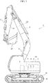
- FIG. 1 is a side view of a hydraulic excavator according to an embodiment
- Fig. 2 is a configuration diagram of a system of the hydraulic excavator according to the embodiment.
- a hydraulic excavator 1 according to the present embodiment is a hybrid hydraulic excavator that drives a main pump 4 with an engine 2 and an assist motor 3.
- the pressure oil supplied from the main pump 4 is distributed by a control valve 5 and supplied to a plurality of hydraulic actuators (bucket cylinder 6, arm cylinder 7, boom cylinder 8, turning hydraulic motor 9, traveling hydraulic motor 10) so as to perform digging operation, turning operation, and traveling operation.
- the control valve 5 is a flow rate control valve that controls the flow rate of the pressure oil supplied from the main pump 4 to each hydraulic actuator.
- the bucket cylinder 6 is a hydraulic actuator for driving a bucket 26 and is driven by the pressure oil supplied from the main pump 4.
- the arm cylinder 7 is a hydraulic actuator for driving an arm 27 and is driven by the pressure oil supplied from the main pump 4.
- the boom cylinder 8 is a hydraulic actuator for driving a boom 28 and is driven by the pressure oil supplied from the main pump 4.
- the turning hydraulic motor 9 is a hydraulic actuator for turning a turning body 29 with respect to a traveling body 30 and is driven by the pressure oil supplied from the main pump 4.
- the traveling hydraulic motor 10 is a hydraulic actuator for moving forward or backward the traveling body 30 and is driven by the pressure oil supplied from the main pump 4.
- the engine 2 is provided with a starter motor 11 for starting the engine 2.
- the starter motor 11 is driven by electric power supplied from a lead-acid battery (first electrical storage device) 12.
- the lead-acid battery 12 and the starter motor 11 are electrically connected via a first electric system 14.
- the hydraulic excavator 1 includes the vehicle body controller 13 that monitors the state of the vehicle body and controls the vehicle body and also controls the operation or the like of each piece of electrical equipment, and an ECU (engine controller unit) 22 that monitors the state of engine 2 and controls the engine 2.
- the vehicle body controller 13, the ECU 22, and the 24V electrical equipment 16 are electrically connected to the lead-acid battery 12 via a second electric system 15.
- the 24V electrical equipment 16 includes various sensors, a headlight, and the like attached to the hydraulic excavator 1, for example.
- the second electric system 15 is connected in parallel with the first electric system 14 so as to electrically connect the lead-acid battery 12 to the vehicle body controller 13, the 24V electrical equipment 16, and the ECU 22.
- a relay (disconnecting device) 17 is provided in the circuit on the positive electrode side. That is, the relay 17 is configured to be able to disconnect the positive electrode side of the first electric system 14 and the second electric system 15. It should be noted that the relay 17 may not necessarily be configured to be able to disconnect the positive electrode side of the first electric system 14 and the second electric system 15, and may be configured to be able to disconnect the negative electrode side or both of the positive electrode side and the negative electrode side of the first electric system 14 and the second electric system 15.
- the relay 17 is configured to be able to disconnect the power supply from the lead-acid battery 12 to the second electric system 15 by disconnecting connection between the first electric system 14 and the second electric system 15. Closing the relay 17 electrically connects the first electric system 14 and the second electric system 15, and supplies electric power from the lead-acid battery 12 to the vehicle body controller 13, the 24V electrical equipment 16, and the ECU 22. Meanwhile, opening the relay 17 disconnects the connection between the first electric system 14 and the second electric system 15, and disconnects the power supply from the lead-acid battery 12 to the vehicle body controller 13, the 24V electrical equipment 16, and the ECU 22.
- a normally closed relay is used for the relay 17, in which the connection (that is, the closed state) is maintained when a coil is in a non-excited state, for example.
- the assist motor 3 is driven by electric power supplied from a 48V battery (second electrical storage device) 18.
- the assist motor 3 and the 48V battery 18 are electrically connected via a third electric system 19.
- a generator 20 that generates electric power with motive power of the engine 2
- an engine fan 21 that cools a radiator of the engine 2 and is driven by an electric motor (not shown)
- a pilot pump motor 23 that drives a pilot pump 25 are each electrically connected to the 48V battery 18 via the third electric system 19.
- the pilot pump 25 is a pump that supplies pressure oil for operating the control valve 5.
- An electric motor that drives the engine fan 21 is connected to the third electric system 19.
- the 48V battery 18 is configured to supply electric power to the assist motor 3, the engine fan 21, and the pilot pump motor 23, and can be charged with the generator 20.
- the 48V battery 18 supplies electric power to the second electric system 15 via a DC/DC converter 24, which will be described later, and further can charge the lead-acid battery 12 via the second electric system 15.
- the generator 20 supplies electric power to the first electric system 14 and the second electric system 15 via the third electric system 19 and the DC/DC converter 24 (described later).
- the lead-acid battery 12 has a rated voltage of 24V.
- the first electric system 14 and the second electric system 15 are electric systems with a rated voltage of 24V.
- the 48V battery 18 has a rated voltage of 48V.
- the third electric system 19 is an electric system with a rated voltage of 48V.
- the DC/DC converter (voltage converter) 24 is interposed between the second electric system 15 and the third electric system 19 to convert the voltage from the third electric system 19 to the second electric system 15 and supply electric power to the second electric system 15. This allows the electric power generated by the generator 20 to be supplied to the second electric system 15 and the first electric system 14 after the voltage conversion by the DC/DC converter 24, and further allows the lead-acid battery 12 to be charged.
- the vehicle body controller 13 is made up of a microcomputer incorporating, for example, a CPU (Central Processing Unit) that executes operations, a ROM (Read Only Memory) as a secondary storage unit that stores programs for the operations, and a RAM (Random Access Memory) as a temporary storage unit that stores processes of the operations and temporary control variables. By executing the stored programs, the vehicle body controller 13 monitors the state of the vehicle body and controls the vehicle body, and also controls the operation or the like of each piece of electrical equipment.
- a CPU Central Processing Unit
- ROM Read Only Memory
- RAM Random Access Memory
- the vehicle body controller 13 controls the opening and closing of the relay 17 and the operation of the DC/DC converter 24 or the like, and performs various estimation processes and determination processes.
- the vehicle body controller 13 estimates a remaining charge amount of the lead-acid battery 12, disables driving of the starter motor 11 until an estimation result is higher than or equal to a threshold set in advance, and when the estimation result is higher than or equal to the threshold, disconnects the connection between the first electric system 14 and the second electric system 15 by using the relay 17.
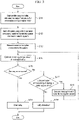
- the startup is an operation that begins by receiving a key-on signal of a key cylinder, starts the engine 2, and then completes all of the starting of the electrical equipment, that is, an operation before the hydraulic excavator 1 enters normal operation.
- the following describes the step of receiving a key-on signal through the step immediately before starting the engine 2, that is, the engine start preparation.
- the step immediately before starting the engine 2 will be referred to as "engine start preparation completion.”
- This "engine start preparation completion" has the same meaning as the estimation result of the remaining charge amount of the lead-acid battery 12 that is higher than or equal to a threshold set in advance, which will be described later.
- step S11 the first electric system 14 and the second electric system 15 are electrically connected since a normally closed relay is used for the relay 17.
- electric power from the lead-acid battery 12 is supplied to the vehicle body controller 13, the 24V electrical equipment 16, and the ECU 22 via the relay 17 and the second electric system 15.
- the vehicle body controller 13 is started and also each piece of electrical equipment of the 24V electrical equipment 16 and the ECU 22 are started. Even after the vehicle body controller 13, the 24V electrical equipment 16, and the ECU 22 are started, the vehicle body controller 13 maintains the relay 17 in a closed state.
- the vehicle body controller 13 disables driving of the starter motor 11. Therefore, until the engine start preparation completion, the starter motor 11 will not be driven even by receiving an engine start signal of a key cylinder, and thus the engine 2 will not be started.
- step S12 following step S11, once the 24V electrical equipment 16 is started, the vehicle body controller 13 starts the 48V battery 18 and the DC/DC converter 24. Then, the vehicle body controller 13 causes the DC/DC converter 24 to convert the electric power of the 48V battery 18 to 24V and starts power supply to the first electric system 14 and the second electric system 15.
- the DC/DC converter 24 detects an electric current supplied from the 48V battery 18 to the second electric system 15 by using a current detection unit (not shown) provided in the DC/DC converter 24, and outputs the detection result to the vehicle body controller 13. Further, an output voltage (i.e., voltage of the second electric system 15) of the DC/DC converter 24 is detected by a voltage detection unit (not shown) provided in the second electric system 15, for example, and the detection result is output to the vehicle body controller 13.
- step S13 power consumption of the second electric system 15 is measured.
- a prescribed value entered to the vehicle body controller 13 based on a designed value may be used, but in this example, a value obtained by measurement is used.
- the electric power supplied from the DC/DC converter 24 to the second electric system 15 is measured in a state where the relay 17 is opened. That is, opening the relay 17 disconnects the connection between the first electric system 14 and the second electric system 15, and the electric power from the DC/DC converter 24 is supplied only to the second electric system 15.
- the electric power to be measured is equal to the power consumption of the second electric system 15.
- step S14 the power supply to the lead-acid battery 12 is restarted in a state where the relay 17 is closed. That is, closing the relay 17 makes connection between the first electric system 14 and the second electric system 15, and thus the electric power from the DC/DC converter 24 is supplied to both of the second electric system 15 and the first electric system 14. Accordingly, a value obtained by the subtraction of the power consumption of the second electric system 15 from the electric power supplied from the DC/DC converter 24 (that is, supply power) is equal to the charging power to the lead-acid battery 12. This allows calculation of a charging current.
- the vehicle body controller 13 measures the voltage while controlling supply current of the DC/DC converter 24 such that the charging current is zero, so as to estimate the remaining charge amount of the lead-acid battery 12.
- step S15 the vehicle body controller 13 compares the remaining charge amount of the lead-acid battery 12 estimated in step S14 (that is, estimation result) with a threshold, and determines whether the engine 2 can be started.
- the threshold is a prescribed value set in advance based on a remaining charge amount sufficient to start the engine 2.
- the vehicle body controller 13 determines that the engine 2 can be started. If an estimation result is lower than the threshold, the vehicle body controller 13 determines that starting the engine 2 is impossible.
- step S16 the vehicle body controller 13 starts also the remaining pieces of electrical equipment and opens the relay 17 after completing the starting so as to disconnect the connection between the first electric system 14 and the second electric system 15. As a result, the engine start preparation is completed. After the end of step S16, a sequential control process ends.
- the vehicle body controller 13 inputs an engine start via a key cylinder. At this time, the starter motor 11 rotates with electric power supplied from the lead-acid battery 12 to start the engine 2.
- the vehicle body controller 13 monitors the number of revolutions of the engine 2 via the ECU 22, and when the number of revolutions is higher than or equal to a prescribed value, determines that starting the engine 2 is completed. After that, the vehicle body controller 13 closes the relay 17 again.
- step S15 the control process proceeds to step S17.
- step S17 the vehicle body controller 13 determines whether the determination of impossibility of starting is within a second time. If the vehicle body controller 13 determines that the determination of impossibility of starting is within a second time, the control process proceeds to step S18.
- step S18 the vehicle body controller 13 increases the supply power of the DC/DC converter 24 that was once reduced for the estimation of the remaining charge amount of the lead-acid battery 12 in step S14, and charges the lead-acid battery 12.
- the vehicle body controller 13 calculates a charging time based on a difference between the remaining charge amount of the lead-acid battery 12 estimated in step S14 and the threshold used in the determination of whether the engine 2 can be started, and an amount of charging current set in advance. Then, the vehicle body controller 13 places the hydraulic excavator 1 in a standby state until the calculated charging time passes (that is, during charging for starting the engine 2). After the charging time passes, the control process goes back to step S14, where the vehicle body controller 13 estimates the remaining charge amount of the lead-acid battery 12 again to determine again whether the engine 2 can be started (see step S15).
- the vehicle body controller 13 During calculation of a charging time and during charging for starting the engine 2 in step S18, the vehicle body controller 13 notifies an operator of the hydraulic excavator 1 or the like that the lead-acid battery 12 is being charged for starting the engine 2. For example, the vehicle body controller 13 notifies the operator that the lead-acid battery 12 is being charged by displaying such a message on a monitor provided in a cab. In addition, the vehicle body controller 13 notifies the operator or the like of a result of the calculated charging time. This can make the operator less stressed, for example.
- step S19 the vehicle body controller 13 determines that the lead-acid battery 12 has broken down, and notifies the operator or the like of the breakdown. For example, the vehicle body controller 13 notifies the operator that the lead-acid battery 12 has broken down by displaying such a message on the monitor provided in the cab. After that, the control process ends.
- the vehicle body controller 13 disconnects the connection between the first electric system 14 and the second electric system 15 by using the relay 17, whereby the lead-acid battery 12 is disconnected from the vehicle body controller 13, the 24V electrical equipment 16, and the ECU 22, or the like.
- the electrical equipment having a likelihood of breakdown and malfunction due to a voltage drop or a voltage ripple such as the vehicle body controller 13, the 24V electrical equipment 16, and the ECU 22, is separated from the lead-acid battery 12 supplying electric power to the starter motor 11, and stably operates with electric power supplied from the 48V battery 18 via the second electric system 15 and the DC/DC converter 24.
- the vehicle body controller 13 when the remaining charge amount of the lead-acid battery 12 is estimated, the vehicle body controller 13 measures the voltage by controlling supply current of the DC/DC converter 24 such that the charging current is zero.
- the present embodiment is not limited thereto.
- the vehicle body controller 13 may store the ON resistance of the lead-acid battery 12 in advance as a prescribed value and accumulate the ON resistance of the lead-acid battery 12 into the charging current so as to estimate a voltage increase amount during charging, whereby an open circuit voltage of the lead-acid battery 12, that is, the remaining charge amount of the lead-acid battery 12, can be estimated.
- the estimation of the remaining charge amount of the lead-acid battery 12 may not necessarily be performed by the vehicle body controller 13.
- the remaining charge amount may be estimated using the battery managing unit.
- the lead-acid battery 12 outputs an estimation result obtained in the battery managing unit to the vehicle body controller 13.
Landscapes
- Engineering & Computer Science (AREA)
- General Engineering & Computer Science (AREA)
- Structural Engineering (AREA)
- Mining & Mineral Resources (AREA)
- Civil Engineering (AREA)
- Power Engineering (AREA)
- General Physics & Mathematics (AREA)
- Physics & Mathematics (AREA)
- Computer Security & Cryptography (AREA)
- Charge And Discharge Circuits For Batteries Or The Like (AREA)
- Operation Control Of Excavators (AREA)
- Control Of Vehicle Engines Or Engines For Specific Uses (AREA)
- Secondary Cells (AREA)
Applications Claiming Priority (1)
| Application Number | Priority Date | Filing Date | Title |
|---|---|---|---|
| PCT/JP2020/014542 WO2021199154A1 (ja) | 2020-03-30 | 2020-03-30 | 建設機械 |
Publications (2)
| Publication Number | Publication Date |
|---|---|
| EP4006239A1 true EP4006239A1 (de) | 2022-06-01 |
| EP4006239A4 EP4006239A4 (de) | 2023-04-26 |
Family
ID=77928146
Family Applications (1)
| Application Number | Title | Priority Date | Filing Date |
|---|---|---|---|
| EP20929334.9A Withdrawn EP4006239A4 (de) | 2020-03-30 | 2020-03-30 | Baumaschine |
Country Status (6)
| Country | Link |
|---|---|
| US (1) | US20220298750A1 (de) |
| EP (1) | EP4006239A4 (de) |
| JP (1) | JP7177967B2 (de) |
| KR (1) | KR20220035489A (de) |
| CN (1) | CN114341440A (de) |
| WO (1) | WO2021199154A1 (de) |
Families Citing this family (2)
| Publication number | Priority date | Publication date | Assignee | Title |
|---|---|---|---|---|
| JP6955524B2 (ja) * | 2019-03-26 | 2021-10-27 | 株式会社日立建機ティエラ | バッテリ式作業機械 |
| CN116838512B (zh) * | 2023-07-03 | 2026-02-24 | 徐州徐工挖掘机械有限公司 | 一种挖掘机发动机启动保护方法、装置及工程机械 |
Family Cites Families (12)
| Publication number | Priority date | Publication date | Assignee | Title |
|---|---|---|---|---|
| JP3948210B2 (ja) * | 2000-12-25 | 2007-07-25 | 日産自動車株式会社 | 車両用エンジンの始動方法および装置 |
| JP5171888B2 (ja) * | 2010-06-09 | 2013-03-27 | 日立建機株式会社 | 建設機械 |
| EP2631373A1 (de) * | 2010-10-22 | 2013-08-28 | Hitachi Construction Machinery Co., Ltd. | Elektrische baumaschine |
| JP2013028962A (ja) | 2011-07-28 | 2013-02-07 | Sumitomo (Shi) Construction Machinery Co Ltd | ハイブリッド型ショベル |
| JP5375917B2 (ja) * | 2011-09-29 | 2013-12-25 | コベルコクレーン株式会社 | 作業機械のバッテリ充放電制御装置 |
| EP3006291B1 (de) * | 2013-05-29 | 2018-05-16 | Nissan Motor Co., Ltd | Steuerungsvorrichtung für ein pulg-in-hybridfahrzeug |
| WO2014196242A1 (ja) * | 2013-06-07 | 2014-12-11 | 日産自動車株式会社 | ハイブリッド車両の制御装置 |
| JP6259380B2 (ja) * | 2014-09-12 | 2018-01-10 | 日立建機株式会社 | ハイブリッド式建設機械 |
| JP2018087496A (ja) | 2015-04-02 | 2018-06-07 | 日立建機株式会社 | ハイブリッド建設機械の始動装置 |
| JP6465907B2 (ja) * | 2017-02-15 | 2019-02-06 | 本田技研工業株式会社 | 車両用電源システム |
| JP6646703B2 (ja) * | 2018-03-27 | 2020-02-14 | 株式会社Subaru | 車両用電源装置 |
| JP6966398B2 (ja) * | 2018-08-29 | 2021-11-17 | 日立建機株式会社 | 建設機械 |
-
2020
- 2020-03-30 US US17/639,424 patent/US20220298750A1/en not_active Abandoned
- 2020-03-30 EP EP20929334.9A patent/EP4006239A4/de not_active Withdrawn
- 2020-03-30 KR KR1020227005796A patent/KR20220035489A/ko not_active Withdrawn
- 2020-03-30 JP JP2022512895A patent/JP7177967B2/ja active Active
- 2020-03-30 CN CN202080061405.XA patent/CN114341440A/zh active Pending
- 2020-03-30 WO PCT/JP2020/014542 patent/WO2021199154A1/ja not_active Ceased
Also Published As
| Publication number | Publication date |
|---|---|
| KR20220035489A (ko) | 2022-03-22 |
| WO2021199154A1 (ja) | 2021-10-07 |
| JP7177967B2 (ja) | 2022-11-24 |
| US20220298750A1 (en) | 2022-09-22 |
| CN114341440A (zh) | 2022-04-12 |
| EP4006239A4 (de) | 2023-04-26 |
| JPWO2021199154A1 (de) | 2021-10-07 |
Similar Documents
| Publication | Publication Date | Title |
|---|---|---|
| EP3611045B1 (de) | Steuergerät für elektrizitätsspeichervorrichtung, elektrisches system und baumaschine | |
| CN114128132B (zh) | 作业机械 | |
| US9956882B2 (en) | Electric power storage system | |
| EP2940827B1 (de) | Elektrische stromversorgungsvorrichtung für ein elektrisches fahrzeug | |
| CN107428254B (zh) | 车辆的电源装置 | |
| US20160138245A1 (en) | Hybrid work machine and method of controlling hybrid work machine | |
| JP6269621B2 (ja) | ハイブリッド建設機械 | |
| EP3767786A1 (de) | Bauausrüstung | |
| EP3553907B1 (de) | Stromversorgungsgerät | |
| US9982416B2 (en) | Shovel and method of controlling shovel | |
| EP4006239A1 (de) | Baumaschine | |
| JP6741878B2 (ja) | 建設機械 | |
| JP6924044B2 (ja) | 電圧印加制御装置 | |
| EP2770120A2 (de) | Schaufel und Verfahren zur Steuerung der Schaufel | |
| JP6315545B2 (ja) | ショベル | |
| EP4144555B1 (de) | Hybrides fahrzeugleistungserzeugungssystem | |
| JP7765312B2 (ja) | 建設機械 | |
| CN116061694B (zh) | 车辆及其供电异常保护系统、方法 | |
| JP2020044921A (ja) | 車両用電源装置 | |
| JP2024059126A (ja) | 作業機械の制御方法、作業機械用制御プログラム、作業機械用制御システム及び作業機械 | |
| JP6315544B2 (ja) | ショベル | |
| JP2012251371A (ja) | 旋回式作業機械 |
Legal Events
| Date | Code | Title | Description |
|---|---|---|---|
| STAA | Information on the status of an ep patent application or granted ep patent |
Free format text: STATUS: THE INTERNATIONAL PUBLICATION HAS BEEN MADE |
|
| PUAI | Public reference made under article 153(3) epc to a published international application that has entered the european phase |
Free format text: ORIGINAL CODE: 0009012 |
|
| STAA | Information on the status of an ep patent application or granted ep patent |
Free format text: STATUS: REQUEST FOR EXAMINATION WAS MADE |
|
| 17P | Request for examination filed |
Effective date: 20220222 |
|
| AK | Designated contracting states |
Kind code of ref document: A1 Designated state(s): AL AT BE BG CH CY CZ DE DK EE ES FI FR GB GR HR HU IE IS IT LI LT LU LV MC MK MT NL NO PL PT RO RS SE SI SK SM TR |
|
| A4 | Supplementary search report drawn up and despatched |
Effective date: 20230328 |
|
| RIC1 | Information provided on ipc code assigned before grant |
Ipc: H02P 4/00 20060101ALI20230322BHEP Ipc: H02P 1/02 20060101ALI20230322BHEP Ipc: E02F 3/43 20060101ALI20230322BHEP Ipc: E02F 9/20 20060101AFI20230322BHEP |
|
| DAV | Request for validation of the european patent (deleted) | ||
| DAX | Request for extension of the european patent (deleted) | ||
| STAA | Information on the status of an ep patent application or granted ep patent |
Free format text: STATUS: THE APPLICATION HAS BEEN WITHDRAWN |
|
| 18W | Application withdrawn |
Effective date: 20231013 |