EP4006251A1 - Verstärktes strukturelement - Google Patents
Verstärktes strukturelement Download PDFInfo
- Publication number
- EP4006251A1 EP4006251A1 EP21197227.8A EP21197227A EP4006251A1 EP 4006251 A1 EP4006251 A1 EP 4006251A1 EP 21197227 A EP21197227 A EP 21197227A EP 4006251 A1 EP4006251 A1 EP 4006251A1
- Authority
- EP
- European Patent Office
- Prior art keywords
- section
- structural element
- central body
- wing
- element according
- Prior art date
- Legal status (The legal status is an assumption and is not a legal conclusion. Google has not performed a legal analysis and makes no representation as to the accuracy of the status listed.)
- Withdrawn
Links
- 238000010276 construction Methods 0.000 claims abstract description 15
- 238000003466 welding Methods 0.000 claims description 5
- 238000010079 rubber tapping Methods 0.000 claims description 2
- 238000005452 bending Methods 0.000 description 4
- 238000004519 manufacturing process Methods 0.000 description 4
- 229910052751 metal Inorganic materials 0.000 description 3
- 239000002184 metal Substances 0.000 description 3
- 229910000831 Steel Inorganic materials 0.000 description 2
- 239000002131 composite material Substances 0.000 description 2
- 239000010959 steel Substances 0.000 description 2
- 229910052782 aluminium Inorganic materials 0.000 description 1
- XAGFODPZIPBFFR-UHFFFAOYSA-N aluminium Chemical compound [Al] XAGFODPZIPBFFR-UHFFFAOYSA-N 0.000 description 1
- 238000004364 calculation method Methods 0.000 description 1
- 238000009749 continuous casting Methods 0.000 description 1
- 238000011437 continuous method Methods 0.000 description 1
- 230000001419 dependent effect Effects 0.000 description 1
- 238000011438 discrete method Methods 0.000 description 1
- 238000009826 distribution Methods 0.000 description 1
- 239000002657 fibrous material Substances 0.000 description 1
- 239000003292 glue Substances 0.000 description 1
- 238000005098 hot rolling Methods 0.000 description 1
- 239000000463 material Substances 0.000 description 1
- 239000011159 matrix material Substances 0.000 description 1
- 238000012986 modification Methods 0.000 description 1
- 230000004048 modification Effects 0.000 description 1
- 239000012783 reinforcing fiber Substances 0.000 description 1
- 230000000284 resting effect Effects 0.000 description 1
- 238000007493 shaping process Methods 0.000 description 1
- 239000007787 solid Substances 0.000 description 1
- 230000003068 static effect Effects 0.000 description 1
Images


Classifications
-
- E—FIXED CONSTRUCTIONS
- E04—BUILDING
- E04C—STRUCTURAL ELEMENTS; BUILDING MATERIALS
- E04C3/00—Structural elongated elements designed for load-supporting
- E04C3/02—Joists; Girders, trusses, or trusslike structures, e.g. prefabricated; Lintels; Transoms; Braces
- E04C3/04—Joists; Girders, trusses, or trusslike structures, e.g. prefabricated; Lintels; Transoms; Braces of metal
- E04C3/06—Joists; Girders, trusses, or trusslike structures, e.g. prefabricated; Lintels; Transoms; Braces of metal with substantially solid, i.e. unapertured, web
- E04C3/07—Joists; Girders, trusses, or trusslike structures, e.g. prefabricated; Lintels; Transoms; Braces of metal with substantially solid, i.e. unapertured, web at least partly of bent or otherwise deformed strip- or sheet-like material
-
- E—FIXED CONSTRUCTIONS
- E04—BUILDING
- E04C—STRUCTURAL ELEMENTS; BUILDING MATERIALS
- E04C3/00—Structural elongated elements designed for load-supporting
- E04C3/02—Joists; Girders, trusses, or trusslike structures, e.g. prefabricated; Lintels; Transoms; Braces
- E04C3/04—Joists; Girders, trusses, or trusslike structures, e.g. prefabricated; Lintels; Transoms; Braces of metal
- E04C3/08—Joists; Girders, trusses, or trusslike structures, e.g. prefabricated; Lintels; Transoms; Braces of metal with apertured web, e.g. with a web consisting of bar-like components; Honeycomb girders
- E04C3/09—Joists; Girders, trusses, or trusslike structures, e.g. prefabricated; Lintels; Transoms; Braces of metal with apertured web, e.g. with a web consisting of bar-like components; Honeycomb girders at least partly of bent or otherwise deformed strip- or sheet-like material
-
- E—FIXED CONSTRUCTIONS
- E04—BUILDING
- E04C—STRUCTURAL ELEMENTS; BUILDING MATERIALS
- E04C3/00—Structural elongated elements designed for load-supporting
- E04C3/02—Joists; Girders, trusses, or trusslike structures, e.g. prefabricated; Lintels; Transoms; Braces
- E04C3/04—Joists; Girders, trusses, or trusslike structures, e.g. prefabricated; Lintels; Transoms; Braces of metal
- E04C2003/0404—Joists; Girders, trusses, or trusslike structures, e.g. prefabricated; Lintels; Transoms; Braces of metal beams, girders, or joists characterised by cross-sectional aspects
- E04C2003/0408—Joists; Girders, trusses, or trusslike structures, e.g. prefabricated; Lintels; Transoms; Braces of metal beams, girders, or joists characterised by cross-sectional aspects characterised by assembly or the cross-section
- E04C2003/0421—Joists; Girders, trusses, or trusslike structures, e.g. prefabricated; Lintels; Transoms; Braces of metal beams, girders, or joists characterised by cross-sectional aspects characterised by assembly or the cross-section comprising one single unitary part
-
- E—FIXED CONSTRUCTIONS
- E04—BUILDING
- E04C—STRUCTURAL ELEMENTS; BUILDING MATERIALS
- E04C3/00—Structural elongated elements designed for load-supporting
- E04C3/02—Joists; Girders, trusses, or trusslike structures, e.g. prefabricated; Lintels; Transoms; Braces
- E04C3/04—Joists; Girders, trusses, or trusslike structures, e.g. prefabricated; Lintels; Transoms; Braces of metal
- E04C2003/0404—Joists; Girders, trusses, or trusslike structures, e.g. prefabricated; Lintels; Transoms; Braces of metal beams, girders, or joists characterised by cross-sectional aspects
- E04C2003/0443—Joists; Girders, trusses, or trusslike structures, e.g. prefabricated; Lintels; Transoms; Braces of metal beams, girders, or joists characterised by cross-sectional aspects characterised by substantial shape of the cross-section
- E04C2003/0452—H- or I-shaped
Definitions
- the present invention relates to a reinforced structural element that can be used for the construction of building structures.
- the present invention relates to a reinforced structural element constituting a beam.
- a double “T” beam as it is known, comprises a first and a second wing, which are spaced apart and parallel to each other and mutually connected through a central body called "core".
- WO2019123388A1 concerns a lightweight structural element shaped as a double "T" beam with two wings spaced apart and parallel to each other, and a central body, the core, which extends between the first wing and the second wing, thereby connecting them.
- This structural element when used in combination with other elements in the construction of building structures, requires high mechanical strength and improved load bearing.
- the points of the structural element that are most subject to mechanical stress are the wings and the connection points between the wings and the core of the beam.
- the lightweight structural element discussed in WO2019123388A1 could have very heavy load and strength limits, if used in the construction of building structures.
- the main object of the present invention is to improve the state of the art concerning the structural elements that can be used in the construction of building structures.
- Another object of the present invention is to provide a structural element that can be used in the construction of building structures capable of supporting loads higher than the solutions in accordance with the state of the art as well as providing a high mechanical resistance to stress.
- a further object of the present invention is to provide a reinforced structural element of practical use and construction, in the context of a flexible use solution that facilitates the production of various formats, if desired with overall dimensions that are different from each other, according to specific needs of use.
- Another object of the present invention is to provide a structural element capable of replacing the C-shaped press-folded steel profiles currently used as covering beams or ceilings, providing the same characteristics of lightness and also being free from torsion problems occurring with C-shaped profiles.
- a structural element which can be used for the construction of a building structure according to claim 1.
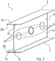
- the structural element 1 is basically configured as a double "T" beam.
- the structural element can be obtained by profiling or press bending of a sheet strip, for example galvanized, with small thickness, if desired between 1 and 10 mm or better between 3 and 7 mm, which sheet is therefore obtained in a single piece.
- the sheet strip has a first wing 2, a second wing 3 spaced apart and substantially parallel to each other, and a central body or core 4 which extends between the first wing 2 and the second wing 3, connecting them or in any case constituting a section of connection or continuation between wings 2, 3.
- the central body 4 is preferably substantially orthogonal to the main extension dimension or width of the first wing 2 and of the second wing 3 and has a first surface 5 and a second surface 6 opposite each other.
- the central body 4 essentially consists of an intermediate part of the sheet and is preferably flat.
- This construction as a single body allows to optimize the timing necessary for the production of the structural element 1.
- the structural element 1 can be made by bending a metal sheet, for example a metal strip, so as to configure the first wing 2, the second wing 3 and the central body 4.
- the material of the sheet or strip can be steel with different strengths and thicknesses according to specific use requirements or even aluminum.
- the structural element 1 can be made by means of a sheet or a strip or the like made of composite material.
- the composite material can preferably comprise fiber material of the type comprising at least reinforcing fibers associated or embedded in a matrix.
- the structural element 1 comprises a first dimension or height H substantially defined by the main extension dimension of the central body 4, a second dimension or width W substantially defined by the main extension dimension of the wings 2, 3 and a third dimension or length L or longitudinal development, which is orthogonal to the other two dimensions.
- the structural element 1 has a front or cross section substantially defined in the plane identified by the first H and the second W dimension, which extends or repeats or remains constant along the longitudinal extension of the element 1 (see figure 3 ), that is the extension of the element 1 along the third dimension or length L (see figures 1 and 2 ).
- the structural element 1 is configured in such a way that the first wing 2 and the second wing 3 each have at least one first section 2a, 3a and at least one second section 2b, 3b overlapping or side by side.
- the first section 2a, 3a and the second section 2b, 3b are preferably flat.
- each wing 2, 3 the first and second section are approached or rested against each other, so that the area between them has a width of less than 5 mm, even more preferably less than 2 or 1 mm, if desired with the two sections abutting one against the other or rather folded one over the other.
- the first section 2a, 3a and the second section 2b, 3b are advantageously parallel and orthogonal to the central body 4.
- first section 2a, 3a and the second section 2b, 3b of each wing 2, 3 are connected to each other by spot welding or also by other suitable continuous or discrete method, for example glue, screws, rivets, etcetera.
- This connection allows to oppose, in addition to providing a solid connection between the sections 2a, 3a and 2b, 3b, phenomena of local instability of the sheet forming the profile and is useful for obtaining a wing 2, 3 of reduced thickness and consequently, a structural element 1 with a lower overall weight, while at the same time maintaining a high solidity and mechanical resistance to stresses.
- both the first 2 and the second wing 3 also comprise a third section 2d, 3d of the sheet extending from the central body 4 and between the latter and a first end 2a1, 3a1 of the first section 2a, 3a, while the second section 2b, 3b extends from a second end 2a2, 3a2 of the first section 2a, 3a approaching the central body 4.
- the third section 2d, 3d is substantially aligned with the second section 2b, 3b, so that each wing 2, 3 comprises in succession starting from a respective end of the central body 4, the third section 2d, 3d, the first section 2a, 3a and the second section 2b, 3b, between the first 2a, 3a and the third 2d, 3d section being provided a first connecting or continuation piece 2e, 3e, if desired curved, preferably substantially U-shaped, and between the first 2a, 3a and the second section 2b, 3b being provided a second connecting or continuation piece 2f, 3f, if desired curved, preferably substantially U-shaped.
- the third section 2d, 3d has an extension equal to the second section 2b, 3b, while the first section 2a, 3a has an extension substantially equal to the sum of the second 2b, 3b and the third section 2d, 3d.
- the second 2b, 3b and the third section 2d, 3d are superimposed or placed side by side with a respective first section 2a, 3a so that the area between them, i.e. between the second 2b, 3b and the third 2d, 3d, on the one hand, and the first section 2a, 3a, on the other hand, has a width less than 5 mm.
- the width W of the structural element is defined by the width of the first section 2a, 3a or by the sum of the width of the second 2b, 3b and third section 2d, 3d.
- the third section 2d, 3d is preferably flat.
- the third section 2d, 3d is advantageously orthogonal to the central body 4.
- the structural element 1 is shaped like an IPE beam, in particular an IPE 270 beam, although it is understood that the same can in any case have further configurations, in which the proportions between the wings and the central body can be different, even if they fall within the same inventive concept of the present invention.
- the central body 4 has an extension or height between about 200 and about 300 mm, for example about 270 mm.
- the two wings 2, 3 have an extension or width between about 100 mm and about 150 mm, for example equal to about 135 mm.
- the sheet then comprises at least one free section or edge 2c, 3c extending from one end of one or both of the second sections 2b, 3b, which free section or edge 2c, 3c is substantially parallel and approached to at least one portion 4c of the first and/or of the second surface 5, 6 of the central body 4.
- the free section or edge 2c, 3c is in fact folded over a portion of the first and/or second surface 5, 6 of the central body 4.
- the free section or edge 2c, 3c is connected to the at least one portion of the first and/or second surface 5, 6 of the central body 4 by means of suitable connection means, for example by welding, one or more self-tapping screws and/or one or more rivets.
- the free section or edge 2c, 3c is orthogonal to the second section 2b, 3b from which it extends.
- the purpose is to stiffen the sections 2b and 3b in order to avoid local instability phenomena in these sections of the profile and to make the width completely effective and not to be partialized in the static calculation phase.
- the free section or edge 2c, 3c does not have through openings and the same applies to the respective constraint portion 4c of the central body 4.
- the free section or edge 2c, 3c can have an extension or height between about 5 mm and about 15 mm, if desired equal to or greater than about 10 mm.
- connection means are preferably applied uniformly along the entire longitudinal extension of the structural element. If a weld is provided as a connection means, then it is preferably applied continuously in the direction of the length or longitudinal extension of the structural element 1.
- connection means can also be applied discontinuously, if desired by points or areas.
- connection means involve or are applied for a good part, at least 70%, 80% of the length of the structural element 1.
- the structural element or rather the respective metal has each of the two wings 2, 3 which comprises, in sequence, starting from a respective end 4a, 4b of the central body or core 4:
- the longitudinal symmetry plane of the structural element 1 is defined by the height H and length L of the latter and the central body or core 4 preferably lies in it.
- the two free sections or edges 2c, 3c thus constitute the free ends of the sheet which, following bending or appropriate shaping of the sheet, are close to or abutting with a respective portion 4c of the central body or core 4 at a respective end 4a, 4b of the latter.
- payload we mean the maximum variable load that the structural element can withstand without breaking.
- the central body 4 which can have different lengths L according to specific needs, can advantageously delimit a through opening 8 or a plurality of through openings 8 along its longitudinal extension.
- the through openings 8 can be made along the sheet or the strip prior to the step of folding or forming the same, thereby simplifying its construction.
- the structural element 1 comprises at least one aligned row of through openings 8 extending along the central body 4, for example in a central position.
- the structural element 1 can comprise two or more rows of through openings 8 which extend along the central body 4.
- the through opening 8 or each of the through openings 8 is delimited along its entire perimeter by a raised edge 9 which extends from one side of the central body 4, outside the first surface 5 or the second surface 6 and results resting on it.
- the raised edge 9 is folded on itself acting as a stiffening element for the portion of the central body 4 at the through opening 8.
- the raised edge 9 of all the through openings 8 to be found along the central body 4 can protrude from the same side of the central body 4 itself, i.e. from the first surface 5 or from the second surface 6.
- some through openings 8 may have the respective raised edge 9 which protrudes from the first surface 5 while other through openings 8 may have the respective raised edge 9 which protrudes from the second surface 6.
- the raised edge 9 can protrude alternately from the first surface 5 or from the second surface 6 at least every two or more through openings 8 in succession along the central body 4 or according to a distribution any, alternating or non-alternating, according to specific needs of use, without any limitation.
- the through openings 8 can be circular or elliptical shaped.
- the through openings 8 allow the passage of cables and utilities through the central body 4 of the structural element 1.
- the raised edge 9 at each of the through openings 8 facilitates the sliding of a cable or a utility through the central body 4, preventing unwanted jamming from occurring due to the presence of an edge pointy or sharp.
- the structural element may not have through openings 8 (see in particular figure 1 ).
- connection of the first section 2a, 3a with the second section 2b, 3b by spot welding allows to obtain a very compact structural element 1.
Landscapes
- Engineering & Computer Science (AREA)
- Architecture (AREA)
- Civil Engineering (AREA)
- Structural Engineering (AREA)
- Golf Clubs (AREA)
- Laminated Bodies (AREA)
- Rod-Shaped Construction Members (AREA)
Applications Claiming Priority (1)
| Application Number | Priority Date | Filing Date | Title |
|---|---|---|---|
| IT102020000028835A IT202000028835A1 (it) | 2020-11-27 | 2020-11-27 | Elemento strutturale rinforzato |
Publications (1)
| Publication Number | Publication Date |
|---|---|
| EP4006251A1 true EP4006251A1 (de) | 2022-06-01 |
Family
ID=74592547
Family Applications (1)
| Application Number | Title | Priority Date | Filing Date |
|---|---|---|---|
| EP21197227.8A Withdrawn EP4006251A1 (de) | 2020-11-27 | 2021-09-16 | Verstärktes strukturelement |
Country Status (2)
| Country | Link |
|---|---|
| EP (1) | EP4006251A1 (de) |
| IT (1) | IT202000028835A1 (de) |
Citations (7)
| Publication number | Priority date | Publication date | Assignee | Title |
|---|---|---|---|---|
| US2065378A (en) * | 1935-12-13 | 1936-12-22 | Fred E Kling | Structural shape |
| GB561505A (en) * | 1942-08-18 | 1944-05-23 | Mills Scaffold Co Ltd | Improvements in or relating to metal constructional members |
| US2384849A (en) * | 1943-06-23 | 1945-09-18 | Nat Steel Corp | Structural member |
| DE2459421A1 (de) * | 1974-12-16 | 1976-06-24 | Galler Kg | Kaltgewalzter profiltraeger aus stahlblech |
| WO1999038416A1 (de) * | 1998-01-30 | 1999-08-05 | Tegometall (International) Ag | Regaltraverse |
| WO2000034599A1 (en) * | 1997-05-23 | 2000-06-15 | Roger Ericsson | Lightweight i-beam and lightweight building unit |
| WO2019123388A1 (en) | 2017-12-22 | 2019-06-27 | Manni Green Tech S.R.L. | Frame structure for walls |
-
2020
- 2020-11-27 IT IT102020000028835A patent/IT202000028835A1/it unknown
-
2021
- 2021-09-16 EP EP21197227.8A patent/EP4006251A1/de not_active Withdrawn
Patent Citations (7)
| Publication number | Priority date | Publication date | Assignee | Title |
|---|---|---|---|---|
| US2065378A (en) * | 1935-12-13 | 1936-12-22 | Fred E Kling | Structural shape |
| GB561505A (en) * | 1942-08-18 | 1944-05-23 | Mills Scaffold Co Ltd | Improvements in or relating to metal constructional members |
| US2384849A (en) * | 1943-06-23 | 1945-09-18 | Nat Steel Corp | Structural member |
| DE2459421A1 (de) * | 1974-12-16 | 1976-06-24 | Galler Kg | Kaltgewalzter profiltraeger aus stahlblech |
| WO2000034599A1 (en) * | 1997-05-23 | 2000-06-15 | Roger Ericsson | Lightweight i-beam and lightweight building unit |
| WO1999038416A1 (de) * | 1998-01-30 | 1999-08-05 | Tegometall (International) Ag | Regaltraverse |
| WO2019123388A1 (en) | 2017-12-22 | 2019-06-27 | Manni Green Tech S.R.L. | Frame structure for walls |
Also Published As
| Publication number | Publication date |
|---|---|
| IT202000028835A1 (it) | 2022-05-27 |
Similar Documents
| Publication | Publication Date | Title |
|---|---|---|
| US3381439A (en) | Structural member | |
| US5527625A (en) | Roll formed metal member with reinforcement indentations | |
| JP4563384B2 (ja) | 改良型ビーム | |
| US1924881A (en) | Open truss girder | |
| US8359813B2 (en) | Steel stud with openings and edge formations and method | |
| EP0649949A1 (de) | Bauträger | |
| EP0469909A1 (de) | Profilträger | |
| WO2003057931A2 (en) | Cold-formed steel joists | |
| US2186297A (en) | Space enclosing supporting structure | |
| RU2347049C1 (ru) | Длинномерная несущая конструкция стойка опоры линии электропередачи (варианты) | |
| AU2010324521A1 (en) | Structural element | |
| IT202000028835A1 (it) | Elemento strutturale rinforzato | |
| KR200356605Y1 (ko) | 철제 파이프 빔 | |
| GR900300156T1 (en) | Method for making a display panel, and panel obtained by this method | |
| US20240093489A1 (en) | Improved roll-formed structural member | |
| WO2019150277A1 (en) | Structural element for the realization of a beam | |
| EP0177634B1 (de) | Strukturelement, insbesondere zum Bilden von Gittermasten für elektrische Leitungen | |
| RU2851004C1 (ru) | Составная коробчатая балка | |
| US3108665A (en) | Trellis-work structure composed of shaped metallic sections | |
| KR101371197B1 (ko) | 응력변화에 대응한 하이브리드 경량 철구조물의 제작방법 | |
| KR200200358Y1 (ko) | 단열 및 차음효과가 우수한 경량구조부재 | |
| KR100385430B1 (ko) | 단열 및 차음효과가 우수한 경량구조부재 | |
| WO1999015390A1 (en) | Method for manufacturing a tubular sheet metal beam having corbelled-out end sections and a sheet metal beam manufactured in accordance with the method | |
| WO2000015921A1 (en) | Improvements relating to trusses | |
| ITAN20120070A1 (it) | Struttura reticolare metallica |
Legal Events
| Date | Code | Title | Description |
|---|---|---|---|
| PUAI | Public reference made under article 153(3) epc to a published international application that has entered the european phase |
Free format text: ORIGINAL CODE: 0009012 |
|
| STAA | Information on the status of an ep patent application or granted ep patent |
Free format text: STATUS: THE APPLICATION HAS BEEN PUBLISHED |
|
| AK | Designated contracting states |
Kind code of ref document: A1 Designated state(s): AL AT BE BG CH CY CZ DE DK EE ES FI FR GB GR HR HU IE IS IT LI LT LU LV MC MK MT NL NO PL PT RO RS SE SI SK SM TR |
|
| STAA | Information on the status of an ep patent application or granted ep patent |
Free format text: STATUS: REQUEST FOR EXAMINATION WAS MADE |
|
| 17P | Request for examination filed |
Effective date: 20221130 |
|
| RBV | Designated contracting states (corrected) |
Designated state(s): AL AT BE BG CH CY CZ DE DK EE ES FI FR GB GR HR HU IE IS IT LI LT LU LV MC MK MT NL NO PL PT RO RS SE SI SK SM TR |
|
| RIN1 | Information on inventor provided before grant (corrected) |
Inventor name: BENASCIUTTI, ENRICO |
|
| P01 | Opt-out of the competence of the unified patent court (upc) registered |
Effective date: 20230508 |
|
| STAA | Information on the status of an ep patent application or granted ep patent |
Free format text: STATUS: THE APPLICATION IS DEEMED TO BE WITHDRAWN |
|
| 18D | Application deemed to be withdrawn |
Effective date: 20240403 |